fixed-mounted circuit-breaker up to 40.5 kv, sf -insulated · offshore wind generators ... nxplus...
TRANSCRIPT

Fixed-Mounted Circuit-BreakerSwitchgear Type NXPLUSup to 40.5 kV, SF6-Insulated
Medium-VoltageSwitchgear
Catalog HA 35.512003
Supersedes:Catalog HA 35.51 · 2001
Fixed-Mounted Circuit-Breaker Switchgear Type NXPLUS up to 40.5 kV, SF6-Insulated
2 Siemens HA 35.51 · 2003
Contents Application
Types
© Siemens AG 2003
Page
Application
Types, typical uses 2 to 4
Requirements
Features, safety, technology 4 and 5
Technical Data
Electrical data, dimensions 6Room planning 7
Product Range
Single-busbar panels 8 and 9Double-busbar panels 10 and 11
Design
Single-busbar panel design 12 and 13Double-busbar panel design 14 and 15
Components
Panel interconnection, module coupling 16Switching devices 17Protection, control, indicatingand measuring equipment 18 and 19Mechanical control board 20Instrument transformers 21Panel connection 22 and 23
Standards
Standards, specifications, guidelines 24 to 26
Notes
27
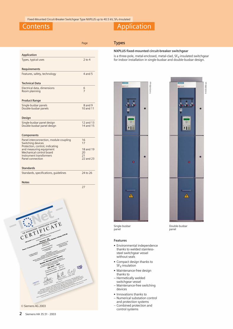
NXPLUS fixed-mounted circuit-breaker switchgear
is a three-pole, metal-enclosed, metal-clad, SF6-insulated switchgearfor indoor installation in single-busbar and double-busbar design.
R-HA
35-0
85b
eps
R-HA
35-0
86b
eps
Single-busbarpanel
Double-busbarpanel
Features
• Environmental independencethanks to welded stainless-steel switchgear vesselwithout seals
• Compact design thanks toSF6-insulation
• Maintenance-free designthanks to
– Hermetically weldedswitchgear vessel
– Maintenance-free switchingdevices
• Innovations thanks to– Numerical substation control
and protection systems– Combined protection and
control systems
Fixed-Mounted Circuit-Breaker Switchgear Type NXPLUS up to 40.5 kV, SF6-Insulated
3Siemens HA 35.51 · 2003 3
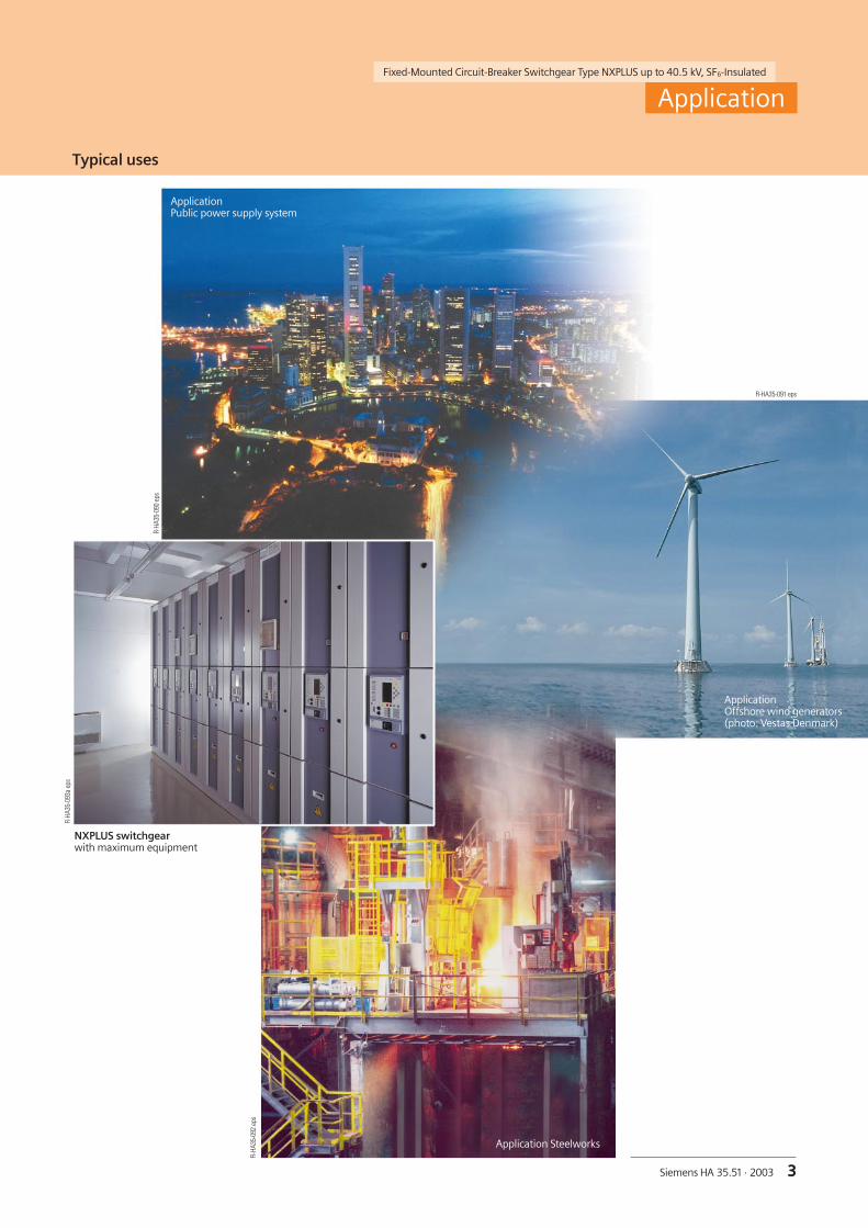
Typical uses
Application
ApplicationPublic power supply system
ApplicationOffshore wind generators(photo: Vestas Denmark)
R-HA
35-0
90ep
s
R-HA
35-0
92ep
s
R-HA
35-0
93a
eps
R-HA35-091 eps
NXPLUS switchgearwith maximum equipment
Application Steelworks

Fixed-Mounted Circuit-Breaker Switchgear Type NXPLUS up to 40.5 kV, SF6-Insulated
4 Siemens HA 35.51 · 2003
Typical uses Features
Application Requirements
Fixed-mounted circuit-breaker switchgearNXPLUS is used in transformerand switching substations, e. g. in:
■ Power supply companies■ Power stations■ Cement industry■ Automobile industry■ Iron and steelworks■ Rolling mills■ Mining industry■ Textile, paper and food industries■ Chemical industry■ Petroleum industry■ Pipeline installations■ Offshore installations■ Electrochemical plants■ Petrochemical plants■ Shipbuilding industry■ Diesel power plants■ Emergency power supply installations■ Lignite open-cast mines■ Traction power supply systems
Environmental independence
Welded switchgear vesselsmade of stainless steel withoutseals and enclosed cable plugsmake NXPLUS switchgear
• Insensitive to aggressive am-bient conditions such as saltwater, humidity, dust andtemperature
• Hermetically tight to ingressof foreign bodies such as dustand dirt
• Independent of site altitude
Compact design
Thanks to the SF6-insulation,compact dimensions arepossible up to 40.5 kV.
Thus,
• Existing switchgear roomscan be used effectively
• Reduced costs for newconstructions
• Expensive city-area space issaved
Maintenance-free design
Switchgear vessels designedas sealed pressure systems,maintenance-free switchingdevices and enclosed cableplugs ensure
• Maximized power supplyreliability
• Personal safety
• Sealed-for-life designaccording to IEC 60 298
• Installation, operation,extension and replacementwithout SF6-gas work
• Reduced operating costs
• Cost-efficient investment
• No maintenance cycles
• Reduced overall LCC(Life-Cycle Cost)
Innovations
The use of numericalsubstation control andprotection systems andcombined protection andcontrol devices ensure
• Clear integration in pro-cess control systems
• Flexible and highly sim-plified adaptation to newsystem conditions andthus to cost-efficientoperation

Fixed-Mounted Circuit-Breaker Switchgear Type NXPLUS up to 40.5 kV, SF6-Insulated
5Siemens HA 35.51 · 2003
Personal safety
• Safe-to-touch and hermeti-cally sealed primary enclo-sure
• All high-voltage parts includ-ing the cable terminations,busbars and voltage trans-formers are surrounded byearthed layers or metal enclo-sures
• Capacitive voltage detectionsystem for verification of safeisolation from supply
• Operating mechanisms andauxiliary switches safely ac-cessible outside the primaryenclosure (switchgear vessel)
• Protective system interlock toprevent operation when theswitchgear enclosure is open
• Standard degree of protec-tion IP 65 (primary part)and IP 3XD (secondary part)according to IEC 60 529 /VDE 0470 Part 1
• High resistance to internalarcs by logical mechanicalinterlocks and tested switch-gear enclosure
• Arc-fault-tested panelsaccording to IEC 60 298 /VDE 0670 Part 6
• Logical mechanical and / orelectrical interlocks preventmaloperation
Operating safety
• Hermetically sealed primaryenclosure independent ofenvironmental effects(dirt, moisture and smallanimals)
• Maintenance-free in anindoor environment(IEC 60 694 / VDE 0670Part 1000)
• Operating mechanisms ofswitching devices accessi-ble outside the switchgearvessel (primary enclosure)
• Metal-enclosed, plug-in in-ductive voltage transform-ers mounted outside thegas compartments
• Ring-core current trans-formers mounted outsidethe gas compartments
• Complete logical mechani-cal interlocking system
• Welded switchgear vessels,sealed for life
• Minimum fire load
• Type and routine-tested
• Standardized, NC produc-tion processes
• Quality assurancein accordance withDIN EN ISO 9001
• More than 300,000switchgear panels ofSiemens in operationworldwide for many years
• Successfully tested for usedown to –20 °C
• Option: Aseismic design
General
• Three-pole enclosure of theprimary part consisting of aswitchgear vessel made ofstainless steel
• Insulating gas SF6
• Three-position switch asbusbar disconnector andfeeder earthing switch
• Make-proof earthing bymeans of the vacuum circuit-breaker
• Outgoing and incomingfeeder panel width: 600 mm
• Hermetically welded switch-gear vessel made of stainlesssteel without seals
• Single-pole, solid-insulated,screened, bolted-typemodule coupling
• Cable connection with insideor outside cone plug-insystems or connection ofsolid-insulated bars
• Wall-standing or free-standing arrangement
• Cable connection access fromfront or rear
• Doors left or right-hinged
• Existing switchgear extend-able on both sides withoutmodification of panels
• Internal panel control cableslaid in metallic cable ducts
Safety
Modular design
• Circuit-breaker modulereplacement possiblewithout SF6-gas work andwithout interruptingbusbar operation
• Low-voltage compartmentcan be removed withoutinterrupting the bus wires
Instrument transformers
• Can be removed withoutaltering the positions of thebusbar and circuit-breakermodules (outside the gascompartments)
Vacuum circuit-breaker
• Maintenance-free undernormal ambient conditionsaccording to IEC 60694 /VDE 0670 Part 1000
• No relubrication orreadjustment
• Up to 10,000 operatingcycles
• Vacuum-tight for life
Interlocks
• According to IEC 60 298 /VDE 0670 Part 6
• Electrical interlocks sinceall mechanisms are motoroperating mechanisms
• Manual emergency operat-ing mechanisms withenabling key S1
Technology
Requirements

Fixed-Mounted Circuit-Breaker Switchgear Type NXPLUS up to 40.5 kV, SF6-Insulated
6 Siemens HA 35.51 · 2003
Electrical data
Technical Data
Rated values
Single-busbar panels
Rated max. kVvoltage
7.2 12 24 36 40.5
Ratedfrequency
50 Hz 1)
Rated short-duration power- kVfrequency withstand voltage
20 28 50 70 85
Rated lightning impulse kVwithstand voltage
60 75 125 170 185
Rated short-circuitbreaking current
max. 31.5 kA
Rated short-timewithstand current, 3 s
max. 31.5 kA
Rated short-circuitmaking current
max. 80 kA
Rated peakwithstand current
max. 80 kA
Rated normal max. Acurrent of busbar
20002)
20002)
20002)
20002)
2000
Rated normal max. Acurrent of feeders
20002)
20002)
20002)
20002)
2000
Dimensions in mm
Single-busbar panels
350
1840
1515
230
1385 39560
935230
230
2
HA35
-242
8b e
ps
PLUSNX
2600
B280
1
350
1600
1515
280 280 935
1145 39560
2
HA35
-242
7c e
ps
PLUSNX
2450
B180
1
Double-busbar panels
Rated max. kVvoltage
7.2 12 24 36
Ratedfrequency
50 Hz 1)
Rated short-duration power- kVfrequency withstand voltage
20 28 50 70
Rated lightning impulse kVwithstand voltage
60 75 125 170
Rated short-circuitbreaking current
max. 31.5 kA
Rated short-timewithstand current, 3 s
max. 31.5 kA
Rated short-circuitmaking current
max. 80 kA
Rated peakwithstand current
max. 80 kA
Rated normal max. Acurrent of busbar
2500 2500 2500 2500
Rated normal max. Acurrent of feeders
2500 2500 2500 2500
1 End wall 2 Busbars
1 End wall 2 Busbars
3) 1200 mm for 2300 / 2500 A
4) 900 mm or 1200 mm for 2300 / 2500 A
1) 60 Hz on request
2) 2500 A on request
Double-busbar panels
Panel width B1
Circuit-breaker panel 600 mm
Disconnector panel 600 mm
Bus sectionalizer panel 900 mm
Panel width B2
Circuit-breaker panel 3) 600 mm
Bus coupler panel 3) 600 mm
Bus sectionalizer panel,system 1 or system 2 4)
600 mm
Metering panel 300 mm

7Siemens HA 35.51 · 2003
Fixed-Mounted Circuit-Breaker Switchgear Type NXPLUS up to 40.5 kV, SF6-Insulated
Technical Data
Room planning
Room planning for single-busbar switchgear
Room planning for double-busbar switchgear
See table on page 6 for dimension B2
* Aisle width
** Free space next to last installed panel,either on left or right of switchgear row
*** Recommended: W 500 mm
See table on page 6 for dimension B1
aaaaaaaaaaaaaaaaaaaaaaaaaaaaaaaaaaaaaaaaaaaaaaaaaaa a aaaaaaaaaaaaaaaaaaaaaaaaaHA35-2407a eps 80³50***
80³500**
³160
0*16
00³5
0
B1B1aaaaaaaaaaaaaaaaaaaaaaaaaaaaaaaaaaaaaaaaaaaaaaaaaaa a aaaaaaaaaaaaaaaaaaaaaaaaaaaaaa a aaaaaaaaaaa a aa aaaaa aaaaaaaaHA35-2408a eps 80³50***
80³50***
80³500**
80³500**
1600
³50
³160
0*16
00³5
0
B1B1
B1B1Single-row arrangement (top view)for single-busbar switchgear
Face-to-face arrangement (top view)for single-busbar switchgearaaaaaaaaaaaaaaaaaaaaaaaaaaaaaaaaaaaaaaaaaaaaaaaaaaa a aaaaaaaaaaaaaaaaaaaaaaaaaaaaaa a aaaaaHA35-2409a eps 80
³50***80
³500**
³160
0*18
40³2
50
B2B2
Single-row arrangement (top view)for double-busbar switchgearaaaaaaaaaaaaaaaaaaaaaaaaaaaaaaaaaaaaaaaaaaaaaaaaaaa a aaaaaaaaaaaaaaaaaaaaaaaaaaaaaa a aaaaaaaaaaa a aa aaaaa aaaaaaaaaaaaaaaaaaaaaaaaaaaaaaHA35-2410a eps 80
³50***
80³50***
80³500**
80³500**
1840
³250
³160
0*18
40³2
50B2B2
B2B2
Face-to-face arrangement (top view)for double-busbar switchgear

HA35
-238
7b e
psHA
35-2
386b
eps
Fixed-Mounted Circuit-Breaker Switchgear Type NXPLUS up to 40.5 kV, SF6-Insulated
8 Siemens HA 35.51 · 2003
Product Range
Single-busbar panels
Circuit-breaker panel
• With cable connection asinside cone for
– Rated voltage up to 40.5 kV– Rated short-circuit breaking
current up to 31.5 kA– Rated normal currents
of busbars and feedersup to 2000 A(2500 A on request)
• With cable connection asoutside cone for
– Rated voltage up to 24 kV– Rated short-circuit breaking
current up to 25 kA(up to 12 kV: 31.5 kA)
– Rated normal currents ofbusbars up to 2000 A(2500 A on request) andfeeders up to 1250 A
Disconnector panel
• With cable connection asinside cone for
– Rated voltage up to 40.5 kV– Rated short-time withstand
current up to 31.5 kA– Rated normal currents
of busbars and feedersup to 2000 A(2500 A on request)
• With cable connection asoutside cone for
– Rated voltage up to 24 kV– Rated short-circuit breaking
current up to 25 kA(up to 12 kV: 31.5 kA)
– Rated normal currents ofbusbars up to 2000 A(2500 A on request) andfeeders up to 1250 A
Bus sectionalizer
for– Rated voltage up to 40.5 kV– Rated short-circuit breaking
current up to 31.5 kA– Rated normal current
of busbars up to 2000 A(2500 A on request)
Circuit-breaker panel (cable connection as inside cone)
Circuit-breaker panel (cable connection as outside cone)
3 x plug-incable,interfacetype 2 or 3
Solid-insulated bar
4 x plug-incable,interfacetype 2
2 x plug-incable,interfacetype 2 or 3
1 x plug-incable,interfacetype 2 or 3
Busbarcurrenttransformer
Surgearrester,plug-in type
Voltagetransformer,plug-in type
or
and2)
or
or
or
or
or
or
Surgearrester,
plug-in type
Currenttrans-
former
Voltagetransformer,plug-in type
Capacitivevoltagedetectionsystem
1 x plug-incable,interfacetype 2
1)
Busbar components
Panel connectioncomponents
Componentsafter circuit-breaker module 3)
Componentsbefore circuit-breaker module
Panel connectionversions
2 x plug-incable
1 x plug-incable
3 x plug-incable
1)
or
and2)
or
or
or
or
3) Requires cableconnection withvessel for separateinside cone
2) Not possiblewith busbarvoltagetransformer
1) Capacitivevoltagedetectionsystem
Currenttrans-
former
Voltagetransformer,disconnect-
able
Capacitivevoltagedetectionsystem
1 x plug-incable,interfacetype 2
Busbarcurrenttransformer
Surgearrester,plug-in type
Voltagetransformer,plug-in type
Panel connectionversions
Panel connectioncomponents
Componentsafter circuit-breaker module
Componentsbefore circuit-breaker module
Surge arresteror limiter,
to be plugged inadditionally
Busbar components

Fixed-Mounted Circuit-Breaker Switchgear Type NXPLUS up to 40.5 kV, SF6-Insulated
9Siemens HA 35.51 · 2003
Single-busbar panels
Product RangeHA
35-2
388b
eps
HA35
-238
9c e
ps
HA35
-239
0b e
ps
Bus sectionalizer
Currenttrans-
former
Capacitivevoltagedetectionsystem
Busbarcomponents
Componentsbefore circuit-breaker module
Componentsbefore bus riser module
1)
Busbar components
Disconnector panel (cable connection as inside cone)
3 x plug-incable,interfacetype 2 or 3
Solid-insulated bar
4 x plug-incable,interfacetype 2
Busbarcurrenttransformer
Surgearrester,plug-in type
Voltagetransformer,plug-in type
or
and2)
or
or
or
and2)
or
or
or
or
or
or
or
or
Surgearrester,
plug-in type
Currenttrans-
former
Voltagetransformer,plug-in type
2 x plug-incable,interfacetype 2 or 3
Capacitivevoltagedetectionsystem
1 x plug-incable,interfacetype 2
1 x plug-incable,interfacetype 2 or 3
Panel connectioncomponents
Panel connectionversions
Disconnector panel (cable connection as outside cone)
Currenttrans-
former
Voltagetransformer,disconnect-
able
2 x plug-incable
Capacitivevoltagedetectionsystem
1 x plug-incable,interfacetype 2
1 x plug-incable
Busbarcurrenttransformer
Surgearrester,plug-in type
Voltagetransformer,plug-in type
3 x plug-incable
1)
Busbar components
Surge arresteror limiter,
to be plugged inadditionally
2) Not possiblewith busbarvoltagetransformer
1) Capacitivevoltagedetectionsystem
Panel connectionversions
Panel connectioncomponents
Componentsafter bus riser module
Componentsbefore cable connection module
Fixed-Mounted Circuit-Breaker Switchgear Type NXPLUS up to 40.5 kV, SF6-Insulated
10 Siemens HA 35.51 · 2003
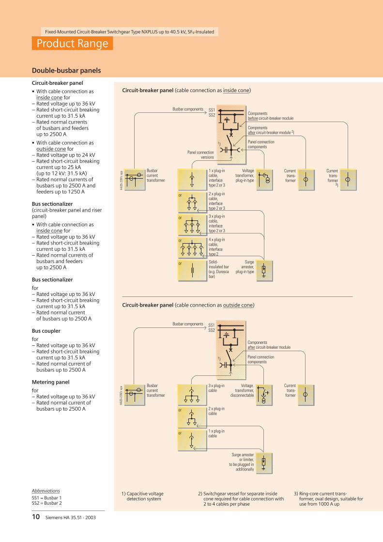
Double-busbar panels
Circuit-breaker panel
• With cable connection asinside cone for
– Rated voltage up to 36 kV– Rated short-circuit breaking
current up to 31.5 kA– Rated normal currents
of busbars and feedersup to 2500 A
• With cable connection asoutside cone for
– Rated voltage up to 24 kV– Rated short-circuit breaking
current up to 25 kA(up to 12 kV: 31.5 kA)
– Rated normal currents ofbusbars up to 2500 A andfeeders up to 1250 A
Bus sectionalizer(circuit-breaker panel and riserpanel)
• With cable connection asinside cone for
– Rated voltage up to 36 kV– Rated short-circuit breaking
current up to 31.5 kA– Rated normal currents of
busbars and feedersup to 2500 A
Bus sectionalizer
for– Rated voltage up to 36 kV– Rated short-circuit breaking
current up to 31.5 kA– Rated normal current
of busbars up to 2500 A
Bus coupler
for– Rated voltage up to 36 kV– Rated short-circuit breaking
current up to 31.5 kA– Rated normal current of
busbars up to 2500 A
Metering panel
for– Rated voltage up to 36 kV– Rated normal current of
busbars up to 2500 A
SS1
HA35
-239
1c e
ps
SS2
1) Capacitive voltagedetection system
3 x plug-incable,interfacetype 2 or 3
Solid-insulated bar(e.g. Durescabar)
4 x plug-incable,interfacetype 2
or
or
or
or
Surgearrester,
plug-in type
Currenttrans-
former
Voltagetransformer,plug-in type
2 x plug-incable,interfacetype 2 or 3
Busbarcurrenttransformer
1 x plug-incable,interfacetype 2 or 3
1)
Busbar components
Panel connectioncomponents
Componentsafter circuit-breaker module 2)
Panel connectionversions
Componentsbefore circuit-breaker module
Currenttrans-
former3)
Circuit-breaker panel (cable connection as outside cone)
SS1
HA35
-239
2c e
ps
SS2
Circuit-breaker panel (cable connection as inside cone)
1 x plug-incable
Surge arresteror limiter,
to be plugged inadditionally
Currenttrans-
former
Voltagetransformer,
disconnectable
2 x plug-incable
Busbarcurrenttransformer
3 x plug-incable
1)
or
or
Panel connectioncomponents
Componentsafter circuit-breaker module
Busbar components
2) Switchgear vessel for separate insidecone required for cable connection with2 to 4 cables per phase
3) Ring-core current trans-former, oval design, suitable foruse from 1000 A up
Abbreviations
SS1 = Busbar 1SS2 = Busbar 2
Product Range

Fixed-Mounted Circuit-Breaker Switchgear Type NXPLUS up to 40.5 kV, SF6-Insulated
11Siemens HA 35.51 · 2003
Double-busbar panels
HA35
-239
3b e
ps
SS1SS2
Componentsbefore circuit-breaker module
Bus sectionalizer (cable connection as inside cone)
Bus coupler
Panel connectioncomponents
3 x plug-incable,interfacetype 2 or 3
2 x plug-incable,interfacetype 2 or 3
1 x plug-incable,interfacetype 2 or 3
4 x plug-incable,interfacetype 2
Solid-insulatedbar
3 x plug-incable,interfacetype 2 or 3
2 x plug-incable,interfacetype 2 or 3
1 x plug-incable,interfacetype 2 or 3
4 x plug-incable,interfacetype 2
Solid-insulatedbar
Voltagetransformer,plug-in type
Currenttrans-
former
Currenttrans-
former
Surgearrester,
plug-in type
Surgearrester,
plug-in type
Bus sectionalizer
HA35
-239
4c e
ps
SS1SS2
1) 1)1) 1)
Panelconnection
versions
Panelconnection
versions
Componentsbefore bus riser module
or
or
or
or
or
or
or
or
Components beforecircuit-breakermodule
Currenttrans-
former
HA35
-239
6a e
ps
SS1SS2
Metering panel
HA35
-239
5b e
ps
SS1SS2 Components before
circuit-breakermodule
Currenttrans-
former
Bus sectionalizer, circuit-breaker panel Bus sectionalizer, bus riser panel
Voltagetransformer,plug-in type
Panel connectioncomponents
1) Capacitive voltagedetection system
Product Range

Fixed-Mounted Circuit-Breaker Switchgear Type NXPLUS up to 40.5 kV, SF6-Insulated
HA35
-239
7c e
ps
PLUSNX7
8
10
11
13
14
15
16
17
18
19
20
21
22
23
12
9
9
24
6
4
3
1
5
9
25
18
26
27
229
24
9
13
28
29 23
18
2
24
12 Siemens HA 35.51 · 2003
Single-busbar panel design
Design
Features
• Stainless-steel module ofcircuit-breaker and busbar
• Sendzimir-galvanized sheet-steel enclosure
• Self-supporting structure
• Electrical connections viacast-resin insulated, screen-ed and bolted module cou-plings
• Low-voltage compartmentcan be removed withoutinterrupting the bus wires
• Degree of protection– IP 65 for primary parts– IP 3XD for secondary parts
• Lateral metallic cable ductsfor control cables
• Suitable for connectingsingle and three-core cablesas well as bars
• Circuit-breaker module re-placement without gas workand without interruptingbusbar operation
• Instrument transformers canbe removed without chang-ing the positions of busbarand circuit-breaker modules
• Instrument transformers canbe removed without gas work(located outside the gas com-partments)
• Maintenance-free vacuumcircuit-breaker under normalambient conditions accordingto IEC 60694 / VDE 0670,Part 1000
• Option: plug-in busbarvoltage transformer
Panel with integrated inside cone
Panel with separate inside cone
Panel with outside cone
1 Door of low-voltage compartment
2 Mimic diagram
3 Multifunction protection relaySIPROTEC 4 type 7SJ61/ 7SJ62for protection and control
4 EMERGENCY-OFF pushbutton,mechanical
5 Door to mechanical control board
6 Cover of connection compartment
7 Busbar cover and space for plug-inbusbar voltage transformer
8 Busbar module, welded,SF6-insulated
9 Rupture diaphragm
10 Three-pole busbar system
11 Three-position disconnector,SF6-insulated, with the three switchpositions:CLOSED – OPEN – READY-TO-EARTH
12 Module coupling between busbarmodule and circuit-breaker module
13 Circuit-breaker module, welded,SF6-insulated, with integrated cableconnection
14 Vacuum interrupter of circuit-breaker
15 Pressure relief duct
16 Integrated cable connection asinside cone
17 Low-voltage compartment,standard: 935 mm high,option: 1100 mm high
18 Ring-core current transformer
19 Manual and motor operatingmechanism of three-positiondisconnector
20 Mechanical control board
21 Manual and motor operatingmechanism of circuit-breaker
22 Voltage transformer connection socket as inside cone
23 Cable connection compartment
24 Voltage transformer
25 Module coupling between circuit-breaker andcable connection module
26 Cable connection module, welded, SF6-insulated,with separate cable connection
27 Separate cable connection as inside cone
28 Voltage transformer connection socket as outside cone
29 Cable connection as outside cone

Fixed-Mounted Circuit-Breaker Switchgear Type NXPLUS up to 40.5 kV, SF6-Insulated
HA35
-242
5d e
ps
31
32
33
34
35
36
30
13Siemens HA 35.51 · 2003
Design
30 Busbar module with three-position disconnector
31 Module couplings between busbar module andcircuit-breaker module
32 Ring-core current transformer
33 Circuit-breaker module with connection for insidecone plug-in system
34 Voltage transformer, can be plugged in via cable
35 Mechanical control board
36 Multifunction protection relay SIPROTEC 4
Modular design
Single-busbar panel design

Fixed-Mounted Circuit-Breaker Switchgear Type NXPLUS up to 40.5 kV, SF6-Insulated
HA35
-240
1b e
ps
PLUSNX1
3
4
5
6
2
23
24
22
21
20
19
18
17
9
12
13
14
9
15
16
11
10
8
7
9
25
31
26
27
24
22
9
9
13
28
29 23
24
31
23
24
22
9
13
16
31
30
14 Siemens HA 35.51 · 2003
Features
• Stainless-steel module ofcircuit-breaker and busbar
• Sendzimir-galvanized sheet-steel enclosure
• Self-supporting structure
• Electrical connections viacast-resin insulated, screen-ed and bolted module cou-plings
• Low-voltage compartmentcan be removed withoutinterrupting the bus wires
• Degree of protection– IP 65 for primary parts– IP 3XD for secondary parts
• Lateral metallic cable ductsfor control cables
• Suitable for connectingsingle and three-core cablesas well as bars
• Circuit-breaker module re-placement without gas workand without interruptingbusbar operation
• Instrument transformers canbe removed without chang-ing the positions of busbarand circuit-breaker modules
• Instrument transformers canbe removed without gas work(located outside the gas com-partments)
• Maintenance-free vacuumcircuit-breaker under normalambient conditions accordingto IEC 60694 / VDE 0670,Part 1000
1 Door of low-voltage compartment
2 Mimic diagram
3 Multifunction protection relaySIPROTEC 4 type 7SJ61/ 7SJ62for protection and control
4 EMERGENCY-OFF pushbutton,mechanical
5 Door to mechanical control board
6 Cover of connection compartment
7 Busbar cover
8 Busbar module (2x), welded,SF6-insulated
9 Rupture diaphragm
10 Three-pole busbar system (2x)
11 Three-position disconnector,SF6-insulated, with the three switchpositions:CLOSED – OPEN – READY-TO-EARTH
12 Module coupling between busbarmodule and circuit-breaker module
13 Circuit-breaker module, welded,SF6-insulated, with integrated cableconnection
14 Vacuum interrupter of circuit-breaker
15 Pressure relief duct
16 Integrated cable connection asinside cone
17 Low-voltage compartment,standard: 935 mm high,option: 1100 mm high
18 Ring-core current transformer,normal or oval design
19 Manual and motor operatingmechanism of three-positiondisconnector
Panel with integrated inside cone
Panel with separate inside cone
Panel with outside cone
Panel with integrated inside cone and currenttransformers in the cable connection compartment
Design
Double-busbar panel design

Fixed-Mounted Circuit-Breaker Switchgear Type NXPLUS up to 40.5 kV, SF6-Insulated
15Siemens HA 35.51 · 2003
HA35
-242
6d e
ps
3332
34 35
36
37
38
39
40
32 Busbar module for SS1with three-position disconnector
33 Busbar module for SS2with three-position disconnector
34 Module couplings between busbar module SS1and circuit-breaker module
35 Module couplings between busbar module SS2and circuit-breaker module
36 Ring-core current transformer, oval design
37 Circuit-breaker module with connectionfor inside cone plug-in system
38 Voltage transformer, can be plugged in via cable
39 Mechanical control board
40 Multifunction protection relay SIPROTEC 4
Modular design (example)
20 Mechanical control board
21 Manual and motor operatingmechanism of circuit-breaker
22 Voltage transformer connectionsocket as inside cone
23 Cable connection compartment
24 Voltage transformer
25 Module coupling betweencircuit-breaker module andcable connection module
26 Cable connection module,welded, SF6-insulated, withseparate cable connection
27 Separate cable connection asinside cone
28 Voltage transformer connectionsocket as outside cone
29 Cable connection as outside cone
30 Connection cables
31 Ring-core current transformer
Continuation of the legend from page 14
Abbreviations
SS1 = Busbar 1SS2 = Busbar 2
Design
Double-busbar panel design

Fixed-Mounted Circuit-Breaker Switchgear Type NXPLUS up to 40.5 kV, SF6-Insulated
16 Siemens HA 35.51 · 2003
Panel interconnection, module coupling
Panel interconnection
• Designed with a modulecoupling
• Solid-insulated
• Connects the panels witheach other, as well as thevessels within a panel
Module coupling
• Single-pole, bolted-type
• Consisting of round copperwith cast-resin insulation
• Bolted busbar joint withsilicone rubber insulation
• Field control by means ofelectrically conductive layersof insulation (inside andoutside)
• Screened by earthing outerlayers with switchgear vessel
• Switchgear installation,extension or panel replace-ment without SF6-gas work
HA35
-237
6e e
ps
8
14
11
12
10
15 13
7
16
9
Module coupling(solid-insulated)
Busbar module,SF6-insulated
Busbar module,SF6-insulated
Module coupling
R-HA
35-0
74ep
s
1 Module coupling
2 Busbar module
3 Current transformer
4 Circuit-breaker module
5 End wall
6 Bushing in adjacent panel
7 Busbar conductor
8 Silicone sleeve
9 Earthing clamps
10 High-quality joint
11 Cast-resin bushing
12 Vessel wall
13 Cast-resin insulation
14 Conductive layer
15 Bolted busbar joint
16 Pressure ring
Panel interconnectionsin the circuit-breaker panel (example)
HA35
-237
5i e
ps
1
62
3
4
3
5
1
HA35
-241
1b e
ps
1 6
2
3
4
3
5
1
Module couplingsfor single-busbar panels
Module couplingsfor double-busbar panels
Components

Fixed-Mounted Circuit-Breaker Switchgear Type NXPLUS up to 40.5 kV, SF6-Insulated
17Siemens HA 35.51 · 2003
Switching devices
Components
Vacuum circuit-breaker
• Three-pole design
• With maintenance-free vac-uum interrupters (= primarypart of the circuit-breaker)in the SF6-filled switchgearvessel
• Force transmission from theoperating mechanism to thecircuit-breaker poles by meansof rods in the switchgearvessel
• Metal bellows, as already usedwith success a million timesfor vacuum interrupters, forgasketless separation of theSF6-insulation and the operat-ing mechanism
Operating mechanism
• Located outside the gas com-partments and behind thepanel front
• Low-lubricant level thanks toappropriate material combina-tions
• Lubricants with anti-seizureproperties and long endurance
• Generally with manual andmotor operating mechanism
• Maintenance-free under nor-mal ambient conditions (inthe switchgear room) andwith maximum permissiblenumber of operating cycles:
Switch positions of the three-position disconnector
“CLOSED”
• Closed current pathbetween busbar andvacuum circuit-breaker
• Contact blades connectedwith fixed contacts at thebusbar bushings
“READY-TO-EARTH”
• Contact blades connectedwith earthing contact ofswitchgear vessel
• Earthing and short-circuit-ing of the cable connec-tion possible by closing thevacuum circuit-breaker
“OPEN”
• Open current pathbetween busbar andvacuum circuit-breaker
• Isolating distanceswithstand prescribed testvoltages
Switching devices
Vacuum circuit-breaker(operating mechanism side open)
1 Vacuum interrupters inSF6-gas
2 Operating mechanismbox
3 Three-positiondisconnector
4 Operating mechanism
R-HA
35-0
73ep
sR-
HA35
-072
eps
Three-position disconnectorwith operating mechanism
4
3
2
1
Mechanical 10000 x
At rated normalcurrent
10000 x
At short-circuitbreaking current
50 x
Three-position disconnector
• Up to 2000 operating cycles
• Compact design thanks toshort contact gaps in SF6-gas
• Operating shaft and contactblade with common pivotpoint and reliable switchposition up to the paneloperating front
• Maintenance-free
Operating mechanism
• Switch position indication viamechanically coupled flag in-dicators
• Separate operating shafts forthe “Disconnecting” and“Ready-to-earth” functions
• Generally with manual andmotor operating mechanism

Fixed-Mounted Circuit-Breaker Switchgear Type NXPLUS up to 40.5 kV, SF6-Insulated
18 Siemens HA 35.51 · 2003
Multifunctionprotection relaySIPROTEC 4 7SJ63
• For stand-alone ormaster operation
• Communications andbus capability
• Functions: control,protection, indicat-ing, communicationsand measuring
• LCD for process andequipment data, inthe form of a feedermimic diagram andas text, e.g. for
– Measuring andmetering values
– Information on statusof switchgear andswitching device
– Protection data– General indications– Alarms
• Four user-program-mable function keysfor frequently per-formed actions
• Fourteen user-pro-grammable LEDs fordisplaying any de-sired data
• Two key-operatedswitches to switchbetween ”local andremote control” and”interlocked andnon-interlocked oper-ation”
• Keys for navigation inmenus and for enter-ing values
• Integrated motorcontrol by specialrelays with enhancedperformance
Legend
1 LCD
2 LEDs
3 Key-operated switches
4 Navigation keys
5 Control keys
6 Function keys
7 LCD (text display)
4
5
6
2
3
R-HA
35-1
02ep
s
• Operating mechanisms forthree-position disconnectorsand circuit-breakers
• Electrical interlocks, option-ally mechanical interlocks forsingle busbar
• Conventional controlsystem or via multifunctionprotection relays
Multifunction protection re-lay SIPROTEC 4 7SJ600/7SJ602
• User-friendly operating pro-gram DIGSI 4 for configura-tion and analysis
• Communications and buscapability
• Functions: control, protec-tion, indicating, communica-tions and measuring
• LCD (2 text lines) and key-board for local operation,configuration and display
• Four user-programmableLEDs for displaying anydesired data
• Operation and fault indica-tion memory
• Fault recording
• Circuit-breaker control
Multifunction protectionrelay SIPROTEC 4 7SJ61/7SJ62
• For stand-alone or masteroperation
• Communications and buscapability
• Functions: control, protec-tion, indicating, communica-tions and measuring
• LCD (4 text lines) for processand equipment data, in theform of a feeder mimic dia-gram and as text, e.g. for
– Measuring and meteringvalues
– Information on status ofswitchgear and switchingdevice
– Protection data– General indications– Alarms
• Four user-programmablefunction keys for frequentlyperformed actions
• Seven user-programmableLEDs for displaying anydesired data
• Keys for navigation in menusand for entering values
Multifunction protection relays SIPROTEC 4
R-HA
35-1
04ep
sR-
HA35
-103
eps
1
7
2
6
4
4
2
7
Protection, control, indicating and measuring equipment (examples)
Multifunction protection relaySIPROTEC 4 7SJ600/7SJ602
Multifunction protection relaySIPROTEC 4 7SJ61/7SJ62
Multifunctionprotection relaySIPROTEC 4 7SJ63
Components

Fixed-Mounted Circuit-Breaker Switchgear Type NXPLUS up to 40.5 kV, SF6-Insulated
19Siemens HA 35.51 · 2003
Indicating and measuring equipment
Ready-for-serviceindicator
• Self-monitoring; easy toread
• Independent of tempera-ture and pressure varia-tions
• Responds only tochanges in gas density
• Contactless measure-ment by means of a BEROproximity switch
Mode of operation
A measurement box in theswitchgear vessel that issealed gas-tight registersthe SF6-gas density, whichcrucially influences the in-sulating capacity. By meansof a coupling magnet,expansion of the measure-ment box is transmitted tothe outside to a solenoidarmature, which then acti-vates the BERO proximityswitch.
Voltage detectionsystems
For voltage detection ac-cording to IEC 61 243-5 /VDE 0682 Part 415
• Detection systems(option):
– LRM oder HR system– Integrated voltage
detection systems,LRM system: CAPDIS-S1and -S2+
LRM or HR system
• With voltage indicator(LRM or HR system)
• Verification of safe isola-tion from supply phaseby phase by insertion ineach socket pair
• Voltage indicator flasheswhen high voltage ispresent
• Indicator suitable forcontinuous operation
• Safe-to-touch
• Routine-tested
• Measuring system andvoltage indicator can betested
• Without auxiliary voltage
Features of integratedvoltage detection systems
Common features
• Maintenance-free
• Integrated display withoutauxiliary power supply
• Integrated, repeated testingof the interfaces (self-testing)
• With integrated function testby pressing the “Display-Test”pushbutton, without auxil-iary power supply
• With integrated 3-phase testsocket for phase comparison(also suitable for plug-involtage indicator)
• Degree of protectionIP 54, temperature range–25 °C to +55 °C
Features of CAPDIS-S1
• Without auxiliary powersupply
• With indication “A1” to “A4”(see legend)
• Without ready-for-servicemonitoring
• Without signalling relay(thus without auxiliarycontacts)
• Integrated circuit capacity
Features of CAPDIS-S2+
• With indication “A1” to “A4”(see legend)
• With indication “ERROR” incase of absent externalauxiliary power supply
• With ready-for-servicemonitoring (auxiliary powersupply required)
• With integrated signallingrelay for signalling “M1” to“M4” (auxiliary power supplyrequired):
– “M1”: Operating voltagepresent at phases L1, L2, L3
– “M2”: Voltage not presentat L1, L2 and L3(= active zero indication)
– “M3”: Earth fault or voltagefailure, e.g. in one phase
– “M4”: Absence of auxiliarypower supply (when voltagepresent or not present)
Ready-for-service indicator
1 Measurement box
2 Magneticcoupling
3 BERO proximityswitch
4 Voltage indicator,LRM system
Voltage detection systems
HA35
-242
4b e
ps�C1
ULE �C2 U2
L2L1
L3
Voltage detectionvia capacitive voltage divider (principle)
–C1 Capacitive coupling electrode integrated into bushing
–C2 Capacity of the connection leads and of the voltage indicatoror voltage detection system to earth
ULE = UN / 3 during rated operation in the three-phase system
U2 = UA =Voltage at the interface of the switchgear or at the voltageindicator or voltage detection system
HA35
-254
2a e
ps
32
1
4
Voltage indicator, LRM system(inserted)
R-HA
35-0
84a
eps
Principle of operationof gas monitoringwith ready-for-service indicator
Stainless-steel vesselfilled with SF6-gas,gauge pressure50 kPa at 20 °C
Ready-for-serviceindicator
plugged-inHR system
mountedCAPDIS-S1
CAPDIS-S1 CAPDIS-S2+
A1
A2
A3
A4
Shown symbolsof the integrated indicatorsCAPDIS-S1 and -S2+
A1 Operating voltagepresent at L1, L2, L3
A2 Voltage not presentat L1, L2, L3
A3 Earth fault or failure in L1,operating voltage at L2, L3
A4 Voltage (not operatingvoltage) presentHA
35-2
543
eps
L2L1 L3 L2L1 L3
Components

Fixed-Mounted Circuit-Breaker Switchgear Type NXPLUS up to 40.5 kV, SF6-Insulated
20 Siemens HA 35.51 · 2003
Mechanical control board
• Located behind the paneldoor
• Opening of door switches offthe electrical control(protection functionprevails)
• Integrated mechanicalswitch position indica-tors in the mimicdiagram
• Clear arrangement ofaccess openings andcontrol elements tothe associated switchposition indicators
• Ergonomically favour-able height of all con-trol elements
Interlocks
Interlocking, eitherpanel-internal or acrossthe panels, is alwayseffected electrically.
In the case of single-busbar panels, panel-internal, mechanicalinterlocking is optionallyavailable, besides electricalinterlocking.
Mechanical interlockingfunctions (optional)
Operation of the three-position disconnector(disconnecting and earth-ing function) is inter-locked with the circuit-breaker.
The operating lever ofthe three-position dis-connector can only beinserted if the circuit-breaker is open and canonly be removed in adefined end position ofthe three-positiondisconnector.
The circuit-breaker canbe closed as soon as theoperating lever has beenremoved and the coverof the three-positiondisconnector has beenclosed.
For safety reasons, themechanical ON push-button of the circuit-breaker is covered andsealed.
De-earthing the feedercan be blocked with thelock-in of the circuit-breaker. This locks electri-cal and mechanical oper-ation at the panel as wellas switching off thecircuit-breaker fromremote. The lock-in ismechanically interlockedwith the “EARTHED” posi-tion of the three-positiondisconnector, with theresult that the mechani-cal locking of the circuit-breaker can only beactivated in the case of“feeder earthed”.
If an undervoltage trip-ping is planned, a possi-bility of locking is alsoplanned.
1 Switch position indicatorCLOSED/OPEN for three-positiondisconnector
2 Operating shaft CLOSED/OPENfor three-position disconnector
3 Operating shaftOPEN/READY-TO-EARTHfor three-position disconnector
4 Switch position indicatorOPEN/READY-TO-EARTHfor three-position disconnector
5 Mimic diagram
6 Interlocking for preselectionto 2 and 3
7 Switch position indicatorCLOSED/OPEN for circuit-breaker
8 Manual charging for circuit-breaker
9 ON pushbutton for circuit-breakerwith sealable cap, mechanical
10 Locking devicefor “feeder earthed”
11 OFF pushbutton forcircuit-breaker, mechanical
12 “Spring charged” indicator forcircuit-breaker
13 Operating cycle counter forcircuit-breaker
R-HA
35-0
88a
eps
1 2 3 4
5
6
10
11
12
13
7
9
8
R-HA
35-0
87a
eps
Mechanical control boardfor single-busbar panels
Mechanical control boardwith open panel door
Components

Fixed-Mounted Circuit-Breaker Switchgear Type NXPLUS up to 40.5 kV, SF6-Insulated
21Siemens HA 35.51 · 2003
Instrument transformers
Current transformers
• Design:– Ring core as the carrier of
the secondary winding– Current path corresponds
to primary winding
• Located outside theprimary enclosure(switchgear vessel)
• Free of dielectricallystressed cast-resin parts(due to design)
• Mounting locations– At the busbar– At the panel connection
• According toIEC 60 044-1 /VDE 0414 Part 1
• Certifiable
Voltage transformers
• Cast-resin insulated
• Inductive type
• Metal-enclosed,safe to touch
• Plug-in type
• Located outside theprimary enclosure(switchgear vessel)
• Mounting locations– At the busbar– At the panel connection
• For 80 % of the ratedshort-duration power-frequency withstandvoltage at rated fre-quency (busbar voltagetransformers)
• Repeat test at 80 % ofthe rated short-durationpower-frequency with-stand voltage withmounted voltage trans-former in the case ofbusbar voltage trans-formers
• According toIEC 60 044-2 /VDE 0414 Part 2
• Certifiable
Ring-core current transformers
Inductive voltage transformers
R-HA
35-0
75ep
sR-
HA35
-076
eps
For outside cone plug-in system
R-HA
35-0
79ep
s
For inside cone plug-in system
R-HA
35-0
78ep
s
For inside cone plug-in system
For outside cone plug-in system
Components

Fixed-Mounted Circuit-Breaker Switchgear Type NXPLUS up to 40.5 kV, SF6-Insulated
22 Siemens HA 35.51 · 2003
Panel connection
3
HA35
-241
2c e
ps
1 2
4
HA35
-241
3c e
ps
4
HA35
-241
4c e
psHA
35-2
416d
eps
6
5
4
HA35
-241
5c e
ps
Inside cone plug-in system
For circuit-breaker anddisconnector panels
Cable connection
• Suitable for bushings accord-ing to DIN EN 50 181
• For connection cross-sectionsup to 630 mm2
• Up to 4 cable sockets and1 voltage transformer socketpossible in each phase
• Designed as cable plug– For inside cone plug-in
system– Metal-enclosed– Fully insulated
• Multiple connections withsockets for identical interfacetypes
Bar connection
• One bar per phase
• Solid-insulated design
Surge arresters
Each cable socket can beequipped with a surge arresterinstead of a cable plug
Cable testing
Cable testing equipment canbe connected after removingthe insulating cover or thevoltage transformer connec-tion cable
Connection versions Cable testing
4 cables per phase (option: surge arrester)Interface type 2
2 cables per phase (option: surge arrester)Interface type 2 or 3
3 cables per phase (option: surge arrester)Interface type 2 or 3
1 cable per phase (option: surge arrester)Interface type 2 or 3
1 solid-insulatedbar per phase
1 Cable sockets
2 Voltage transformer socket
3 Cable plug, interface type 2
4 Cable plug,plug type 2 or 3
5 Silicone sleeve
6 Solid-insulated bar
HA35
-241
7b e
ps
Voltage transformersocket forcable testing
Components

Fixed-Mounted Circuit-Breaker Switchgear Type NXPLUS up to 40.5 kV, SF6-Insulated
23Siemens HA 35.51 · 2003
Panel connection
HA35
-241
8b e
ps
2
1
HA35
-241
9b e
ps
3
HA35
-242
0b e
ps
4
HA35
-242
1b e
ps
5 6
Outside cone plug-insystem
For circuit-breaker anddisconnector panels
Cable connection
• Designed as cable T-plugsuitable for bushingswith outside cone as inter-face type C according toEN 50 181
• Connection cross-sections upto 630 mm2 (larger cross-sections on request)
• Double or triple cable con-nections possible
Surge arresters
• Can be plugged into thecable T-plug of a single ordouble cable connection
• Surge arresters are recom-mended if, at the same time,
– The cable system is directlyconnected to the overheadline
– The protective range of thearrester at the terminal towerof the overhead line does notcover the switchgear
Surge limiters
• Can be plugged into thecable T-plug of a single ordouble cable connection
• Surge limiters are recom-mended if motors areconnected
Cable testing
Cable testing equipment canbe connected after removingthe insulating stopper fromthe cable T-plug
Connection versions Cable testing
Cable testing on themounted cable T-plug
3 cables per phase
2 cables per phase(surge arrester or limiter canbe plugged in additionally)
1 cable per phase(surge arrester or limiter canbe plugged in additionally)
1 Outside cone
2 Triple cable connection
3 Double cable connection
4 Single cable connection
5 Measuring bolt
6 Insulating cap
Components

Fixed-Mounted Circuit-Breaker Switchgear Type NXPLUS up to 40.5 kV, SF6-Insulated
24 Siemens HA 35.51 · 2003
Standards
Standards, specifications, guidelines
Type of service location
NXPLUS switchgear can be usedas an indoor installation inaccordance with IEC 61 936 /VDE 0101:
• Outside lockable electricalservice locations at placeswhich are not accessible tothe public. Enclosures ofswitchgear can only beremoved with tools.
• Inside lockable electricalservice locations. A lockableelectrical service location isa place outdoors or indoorsthat is reserved exclusively forhousing electrical equipmentand which is kept under lockand key. Access is restricted toauthorized personnel and per-sons who have been properlyinstructed in electrical engi-neering. Untrained or un-skilled persons may only enterunder the supervision of au-thorized personnel or properlyinstructed persons.
Insulating capacity
The insulating capacity is veri-fied by testing the switchgearwith rated values of short-duration power-frequencywithstand voltage and light-ning impulse withstand voltageaccording to IEC 60 094 /VDE 0670 Part 1000(see following table):
All parts subjected to high volt-age within the switchgear areinsulated against the earthedoutside enclosure.
This insulation permits installa-tion of the switchgear at anyaltitude above sea level withoutdetrimental influences on thedielectric strength. This alsoapplies to cable connection.
Table – Insulating capacity
Rated voltage kV(r.m.s. value)
7.2 12 15 17.5 24 36 40.5
Rated short-duration power-frequency withstand voltage (r.m.s. value)
– Across isolating distances kV 23 32 40 45 60 80 90
– Between phases and to earth kV 20 28 36 38 50 70 85
Rated lightning impulse withstand voltage (peak value)
– Across isolating distances kV 70 85 105 110 145 195 218
– Between phases and to earth kV 60 75 95 95 125 170 185
Standards
The NXPLUS switchgearcomplies with the relevantstandards and specificationsapplicable at the time of typetests.
In accordance with the harmo-nization agreement reached bythe EU countries, their nationalspecifications conform to theIEC standard.
* In future, all standards for switchingdevices and switchgear will besummarized in IEC 62 271
** Withdrawn standard 1) Circuit-breaker
Overview of standards (December 2002)
2) Disconnector and earthing switch 3) Voltage detection systems
IEC standard VDE standard EN standard
up to now current in future current in future current
Switchgear IEC 60 694 * IEC 60 694 * IEC 62 271-1 VDE 0670 Part 1000 VDE 0671-001 EN 60 694
IEC 60 298 * IEC 60 298 * IEC 62 271-200 VDE 0670 Part 6 VDE 0671-200 EN 60 298
Devices 1) IEC 60 056 ** IEC 62 271-100 IEC 62 271-100 VDE 0670 P. 101 to 106 VDE 0671-100 EN 60 056
2) IEC 60 129 ** IEC 62 271-102 IEC 62 271-102 VDE 0670 Part 2 VDE 0671-102 EN 60 129
3) IEC 61 243-5 IEC 61 243-5 IEC 61 243-5 VDE 0682 Part 415 VDE 0682 Part 415 EN 61 243-5
Degree ofprotection
IEC 60 529 IEC 60 529 IEC 60 529 VDE 0470 Part 1 VDE 0470 Part 1 EN 60 529
Insulation IEC 60 071 IEC 60 071 IEC 60 071 VDE 0111 VDE 0111 EN 60 071
Currenttransformers
IEC 60 044-1 IEC 60 044-1 IEC 60 044-1 VDE 0414 Part 1 VDE 0414 Part 1 EN 60 044-1
Voltagetransformers
IEC 60 044-2 IEC 60 044-2 IEC 60 044-2 VDE 0414 Part 2 VDE 0414 Part 2 EN 60 044-2

Fixed-Mounted Circuit-Breaker Switchgear Type NXPLUS up to 40.5 kV, SF6-Insulated
25Siemens HA 35.51 · 2003
Resistance to internalarc faults
Due to the single-pole enclosureof external components andthe SF6-insulation of switchingdevices, the probability of faultsin NXPLUS fixed-mountedcircuit-breaker switchgear isconsiderably lower than informer switchgear types, as
• There are no effects due toexternal influences such as
– Pollution layers– Moisture– Small animals and foreign
bodies
• Maloperation is practicallyexcluded by logical arrange-ment of the operatingmechanism elements
• The three-position discon-nector and the vacuumcircuit-breaker provideshort-circuit-proof earthingof the feeder
Should arcing occur in spite ofthis, the pressure is relieved to-wards the rear into a duct.
In the unlikely event of a faultinside the module vessel, theenergy conversion in the caseof an internal arc fault is minorthanks to the SF6-insulation,i.e.approximately only ½ com-pared to air. The pressure reliefin the rear wall of the modulevessel operates in the rangeof 2 to 3.5 bar. The escapinggases are discharged to therear into a duct.
The pressure relief duct divertsthe gases upwards.
Current-carrying capacity
• According to IEC 60 298 / VDE0670 Part 6 or IEC 60 694 /VDE 0670 Part 1000, the ratednormal current refers to thefollowing ambient tempera-tures:
– Maximum valueof 24-h mean + 35 °C
– Maximum value + 40 °C
• The current-carrying capacityof the panels and busbars de-pends on the ambient temper-ature outside the enclosure.
Standards, specifications, guidelines
Standards
Tests for resistance to internalarc faults
• Tests for verifying resistance tointernal arc faults should es-tablish proper protection foroperating personnel
• Tests for resistance to internalarc faults can be agreedbetween the owner andmanufacturer in accordancewith IEC 60 298 / VDE 0670Part 6
• All criteria of the abovestandards are met
Aseismic capacity (optional)
NXPLUS switchgear can be up-graded for regions at risk fromearthquakes.
For upgrading, earthquakequalification testing has beencarried out in accordance withthe following standards:
• IEC 68-3-3, 1993
• IEC 68-2-6, 1995
• IABG TA13-TM-002/98(guide)
Within the range of the pre-vailing earthquake frequenciesfrom 1 Hz to 35 Hz, thecategory 1 required responsespectrum according to IABGTA13-TM-002/98 covers thefollowing response spectra:
• Uniform BuildingCode zone 3
• Seismic RequirementsSpec. 9067; Department ofWater & Power, Los Angeles
• GTS – 1.013 ENDESA, Chile
• VDE 0670 Part 111
3
Fixed-Mounted Circuit-Breaker Switchgear Type NXPLUS up to 40.5 kV, SF6-Insulated
26 Siemens HA 35.51 · 2003
Standards, specifications, guidelines
Climate and ambientconditions
NXPLUS switchgear is fullyenclosed and insensitive toclimatic conditions.
• All medium-voltage devicesare installed in a gas-tight,welded stainless-steelswitchgear vessel which isfilled with SF6-gas
• Live parts outside the switch-gear vessel are provided withsingle-pole enclosure
• At no point can creepage cur-rents flow from high-voltagepotentials to earth
• Operating mechanism partswhich are functionally impor-tant are made of corrosion-resistant materials
• Bearings in operating mecha-nisms are designed as drybearings and do not requirelubrication
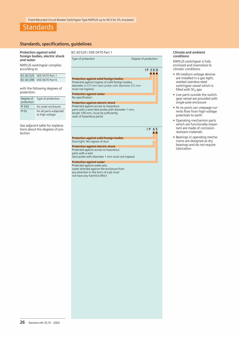
IEC 60529 / VDE 0470 Part 1
Type of protection Degree of protection
I P 3 X Dsss
Protection against solid foreign bodiesProtected against ingress of solid foreign bodies,diameter W 2.5 mm (test probe with diameter 2.5 mmmust not ingress)
Protection against waterNo specification
Protection against electric shockProtected against access to hazardousparts with a wire (test probe with diameter 1 mm,length 100 mm, must be sufficientlyclear of hazardous parts)
I P 6 5ss
Protection against solid foreign bodiesDust-tight: No ingress of dust
Protection against electric shockProtected against access to hazardousparts with a wire(test probe with diameter 1 mm must not ingress)
Protection against waterProtected against water jets;water directed against the enclosure fromany direction in the form of a jet mustnot have any harmful effect
Standards
Protection against solidforeign bodies, electric shockand water
NXPLUS switchgear compliesaccording to
with the following degrees ofprotection:
IEC 60 529 VDE 0470 Part 1
IEC 60 298 VDE 0670 Part 6
Degree ofprotection
Type of protection
IP 3XD for outer enclosure
IP 65 for all parts subjectedto high voltage
See adjacent table for explana-tions about the degrees of pro-tection

27Siemens HA 35.51 · 2003
If not stated otherwise onthe individual pages of thiscatalog, we reserve the rightto include modifications,especially regarding thestated values, dimensionsand weights.
Drawings are not binding.
All product designationsused are trademarks orproduct names ofSiemens AG or othersuppliers.
If not stated otherwise,all dimensions in thiscatalog are given in mm.
Responsible for
Technical contents:Herbert SoensSiemens AG, Dept. PTD M 2 S2Erlangen
General editing:Gabriele PollokSiemens AG, Dept. PTD CC TErlangen
Printed in GermanyKGK 10.03 5.0 VO/- 24 En 100793 6101/D6301
Notes

www.siemens.com/medium-voltage-switchgear
If you have any questions aboutPower Transmission and Distribution,our Customer Support Centeris available around the clock
Tel.: +49 180 / 524 70 00Fax: +49 180 / 524 24 71
E-mail: [email protected]/ptd-support
(Subject to charges,e.g.: 12 ct/min.)
Published by
Siemens AG
Power Transmission and DistributionMedium Voltage DivisionPostfach 32 20
91050 ErlangenGermany
Order No.: E50001-K1435-A511-A4-7600