fks - mk1 user manual u -...
TRANSCRIPT

USER MANUAL ISTRUZIONI D'USO
FKS - MK1
170.IU0.FKS.100 01.03
Nuovo-1.pmd 09/09/2003, 16.251
GBINDEX
1. MOUNTING ............................................................. 12. CONNECTIONS ....................................................... 1
2.1 Measuring inputs ............................................... 12.1.1RTD input .................................................. 22.1.2Linear input ............................................... 2
2.2 Relay outs .......................................................... 32.2.1Voltage outs for SSR drive ........................ 3
2.3 Power line .......................................................... 43. HARDWARE SETTINGS ........................................ 44. THE INSTRUMENT MODE OF WORKING ............ 55. CONFIGURATION .................................................. 5
5.1 Keyboard functions during configuration mode 55.2 How to start the configuration mode ................. 5
5.2.1Instrument in UNLOCK MODE ................. 65.2.2Instrument in LOCK MODE ....................... 6
5.3 Configuration parameters ................................. 66. OPERATING MODE .............................................. 12
6.1 Keyboard functions during operative mode .... 126.2 Alternative displays .......................................... 126.3 Indicators (beacons) ........................................ 136.4 How to check or modify the operative
parameters ....................................................... 136.5 Operating parameters ..................................... 136.6 Enabling/disabling the control output .............. 176.7 Direct modification of the set point .................. 176.8 SMART function ............................................... 176.9 SOFT START function ..................................... 17
7. EXTRA FUNCTIONS ............................................. 187.1 Lamp test ......................................................... 187.2 Firmware version ............................................. 18
8. ERROR MESSAGES ............................................. 188.1 Indication of out of field and/or sensor breaks 188.2 Error messages ............................................... 19
9. TECHNICAL FEATURES ....................................... 2010. DEFAULT PARAMETERS ..................................... A.1
10.1Default values for operating / configurationparameters ...................................................... A.2
10.2 Default values for operating parameters ....... A.2How to order ................................................... A.3Safety code ..................................................... A.3
GB
INDICE
1. MONTAGGIO ........................................................... 12. COLLEGAMENTI ..................................................... 1
2.1 Ingressi di misura .............................................. 12.1.1Ingresso da RTD ....................................... 22.1.2Ingresso lineare ......................................... 2
2.2 Uscite a relè ....................................................... 32.2.1Uscite per il comando di SSR ................... 3
2.3 Alimentazione .................................................... 43. IMPOSTAZIONI HARDWARE ................................. 44. MODALITA' DI FUNZIONAMENTO DELLO
STRUMENTO .......................................................... 55. CONFIGURAZIONE ................................................ 5
5.1 Funzioni della tastiera in modalità diconfigurazione ................................................... 5
5.2 Come avviare la modalità di configurazione ..... 55.2.1 Strumenti in modalità non protetta .......... 65.2.2 Strumenti in modalità protetta .................. 6
5.3 Parametri di configurazione ............................... 66. MODO OPERATIVO .............................................. 12
6.1 Funzioni della tastiera nella modal. operativa . 126.2 Visualizzazioni alternative ............................... 126.3 Indicatori luminosi ............................................ 136.4 Come controllare o modificare i parametri
operativi ........................................................... 136.5 Parametri operativi .......................................... 136.6 Abilitaz./disabilitaz. dell'uscita regolante ......... 176.7 Modifica diretta del set point ............................ 176.8 Funzione SMART ............................................ 176.9 Funzione SOFT START .................................. 17
7. FUNZIONI SUPPLEMENTARI ............................... 187.1 Lamp test ......................................................... 187.2 Versione del firmware ...................................... 18
8. MESSAGGI DI ERRORE ....................................... 188.1 Indicaz. di fuori campo e/o rotture del sensore 188.2 Messaggi di errore ........................................... 19
9. CARATTERISTICHE TECNICHE .......................... 2010. PARAMETRI DI DEFAULT ................................... A.1
10.1 Valori di default per parametri operativi/configurazione .............................................. A.2
10.2 Valori di default per parametri operativi ........ A.2Come ordinare .............................................. A.3Codice di sicurezza ...................................... A.3
I
FKS-MK1-0-B0.PMD 6/10/03, 11:56 AM2
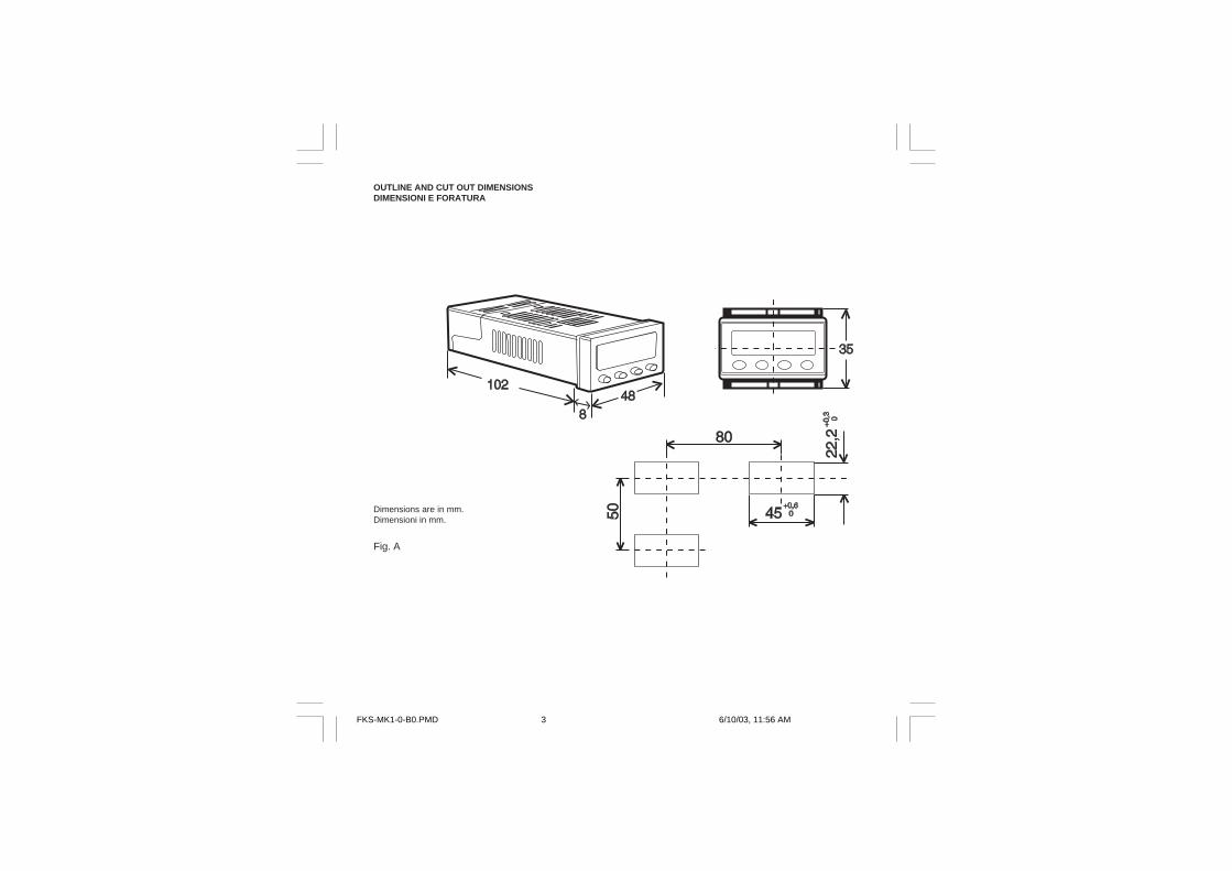
OUTLINE AND CUT OUT DIMENSIONSDIMENSIONI E FORATURA
Dimensions are in mm.Dimensioni in mm.
Fig. A
FKS-MK1-0-B0.PMD 6/10/03, 11:56 AM3
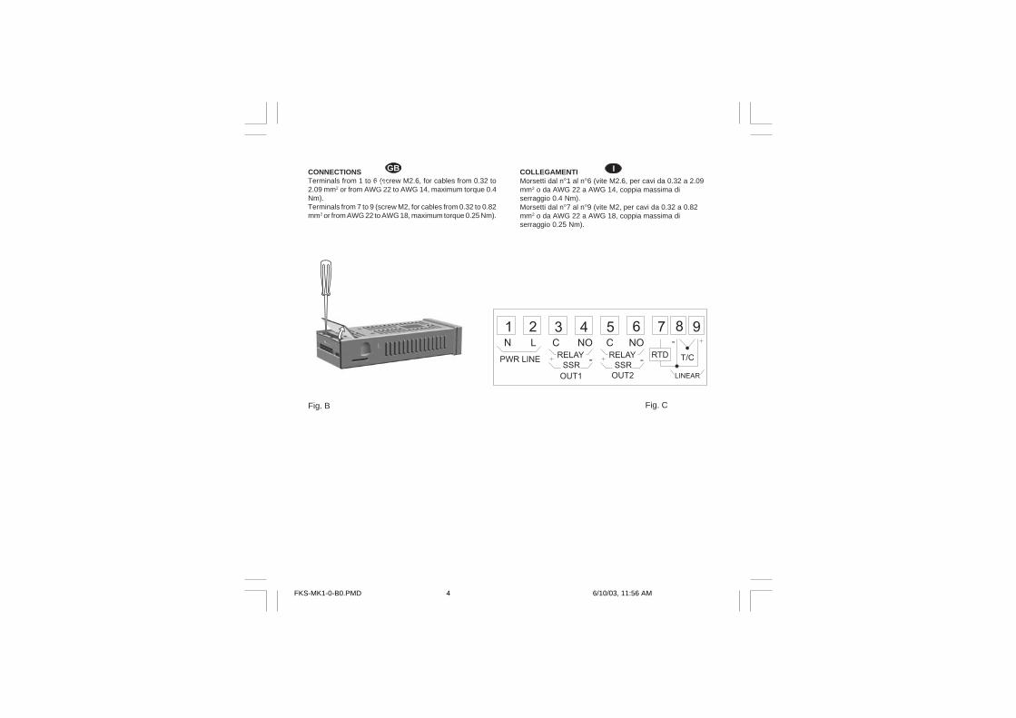
CONNECTIONSTerminals from 1 to 6 (screw M2.6, for cables from 0.32 to2.09 mm2 or from AWG 22 to AWG 14, maximum torque 0.4Nm).Terminals from 7 to 9 (screw M2, for cables from 0.32 to 0.82mm2 or from AWG 22 to AWG 18, maximum torque 0.25 Nm).
Fig. B Fig. C
I
GB
GB COLLEGAMENTIMorsetti dal n°1 al n°6 (vite M2.6, per cavi da 0.32 a 2.09mm2 o da AWG 22 a AWG 14, coppia massima diserraggio 0.4 Nm).Morsetti dal n°7 al n°9 (vite M2, per cavi da 0.32 a 0.82mm2 o da AWG 22 a AWG 18, coppia massima diserraggio 0.25 Nm).
I
FKS-MK1-0-B0.PMD 6/10/03, 11:56 AM4
1GB
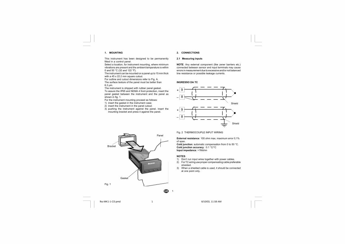
1. MOUNTING
This instrument has been designed to be permanentlyfitted in a control panel.Select a location, for instrument mounting, where minimumvibrations are present and the ambient temperature is within0 and 50 °C (32 and 122 °F).The instrument can be mounted on a panel up to 15 mm thickwith a 45 x 22.2 mm square cutout.For outline and cutout dimensions refer to Fig. A.The surface texture of the panel must be better than6,3 µm.The instrument is shipped with rubber panel gasket.To assure the IP65 and NEMA 4 front protection, insert thepanel gasket between the instrument and the panel asshown in fig. 1.For the instrument mounting proceed as follows:1) insert the gasket in the instrument case;2) insert the instrument in the panel cutout;3) pushing the instrument against the panel, insert the
mounting bracket and press it against the panel.
Fig. 1
Gasket
Bracket
Panel
2. CONNECTIONS
2.1 Measuring inputs
NOTE: Any external component (like zener barriers etc.)connected between sensor and input terminals may causeerrors in measurement due to excessive and/or not balancedline resistance or possible leakage currents.
INGRESSO DA TC
Fig. 2 THERMOCOUPLE INPUT WIRING
External resistance: 100 ohm max, maximum error 0,1%of span.Cold junction: automatic compensation from 0 to 50 °C.Cold junction accuracy : 0.1 °C/°CInput impedance: >1Mohm
NOTES:1) Don’t run input wires together with power cables.2) For TC wiring use proper compensating cable preferable
shielded.3) When a shielded cable is used, it should be connected
at one point only.
8
+
_
Shield
9
8
+
_
Shield
9
fks-MK1-1-C0.pmd 6/10/03, 11:59 AM1
2GB
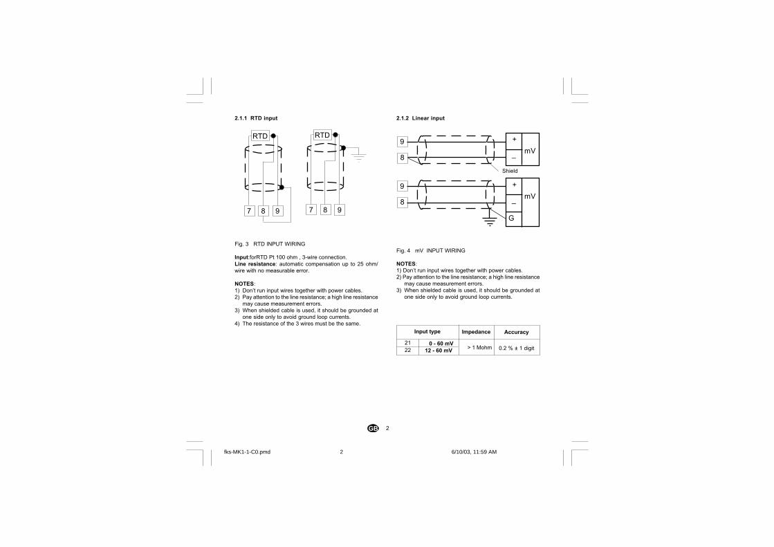
2.1.2 Linear input
Fig. 4 mV INPUT WIRING
NOTES:1) Don’t run input wires together with power cables.2) Pay attention to the line resistance; a high line resistance
may cause measurement errors.3) When shielded cable is used, it should be grounded at
one side only to avoid ground loop currents.
2.1.1 RTD input
Fig. 3 RTD INPUT WIRING
Input:forRTD Pt 100 ohm , 3-wire connection.Line resistance: automatic compensation up to 25 ohm/wire with no measurable error.
NOTES:1) Don’t run input wires together with power cables.2) Pay attention to the line resistance; a high line resistance
may cause measurement errors.3) When shielded cable is used, it should be grounded at
one side only to avoid ground loop currents.4) The resistance of the 3 wires must be the same.
7
RTD
98 7
RTD
98
8
Shield
9
8
9
G
_
+mV
_
+mV
0 - 60 mV12 - 60 mV > 1 Mohm
Input type
2122
Impedance Accuracy
0.2 % ± 1 digit
fks-MK1-1-C0.pmd 6/10/03, 11:59 AM2
3GB
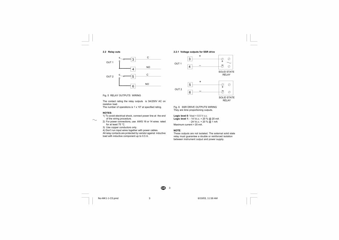
2.2 Relay outs
Fig. 5 RELAY OUTPUTS WIRING
The contact rating the relay outputs is 3A/250V AC onresistive load.The number of operations is 1 x 10⁵ at specified rating.
NOTES:1) To avoid electrical shock, connect power line at the end
of the wiring procedure.2) For power connections, use AWG 16 or 14 wires rated
for at least 75 °C.3) Use copper conductors only.4) Don’t run input wires together with power cables.All relay contacts are protected by varistor against inductiveload with inductive component up to 0.5 A.
2.2.1 Voltage outputs for SSR drive
Fig. 6 SSR DRIVE OUTPUTS WIRINGThey are time proportioning outputs.
Logic level 0: Vout < 0.5 V c.c.Logic level 1: - 14 Vc.c. + 20 % @ 20 mA
- 24 Vc.c. + 20 % @ 1 mAMaximum current = 20 mA.
NOTE:These outputs are not isolated. The external solid staterelay must guarantee a double or reinforced isolationbetween instrument output and power supply.
+
_ _+3
4OUT 1
SOLID STATERELAY
+
_ _+5
6OUT 2
SOLID STATERELAY
OUT 1
C3
4NO
5
6NO
COUT 2
fks-MK1-1-C0.pmd 6/10/03, 11:59 AM3
4GB
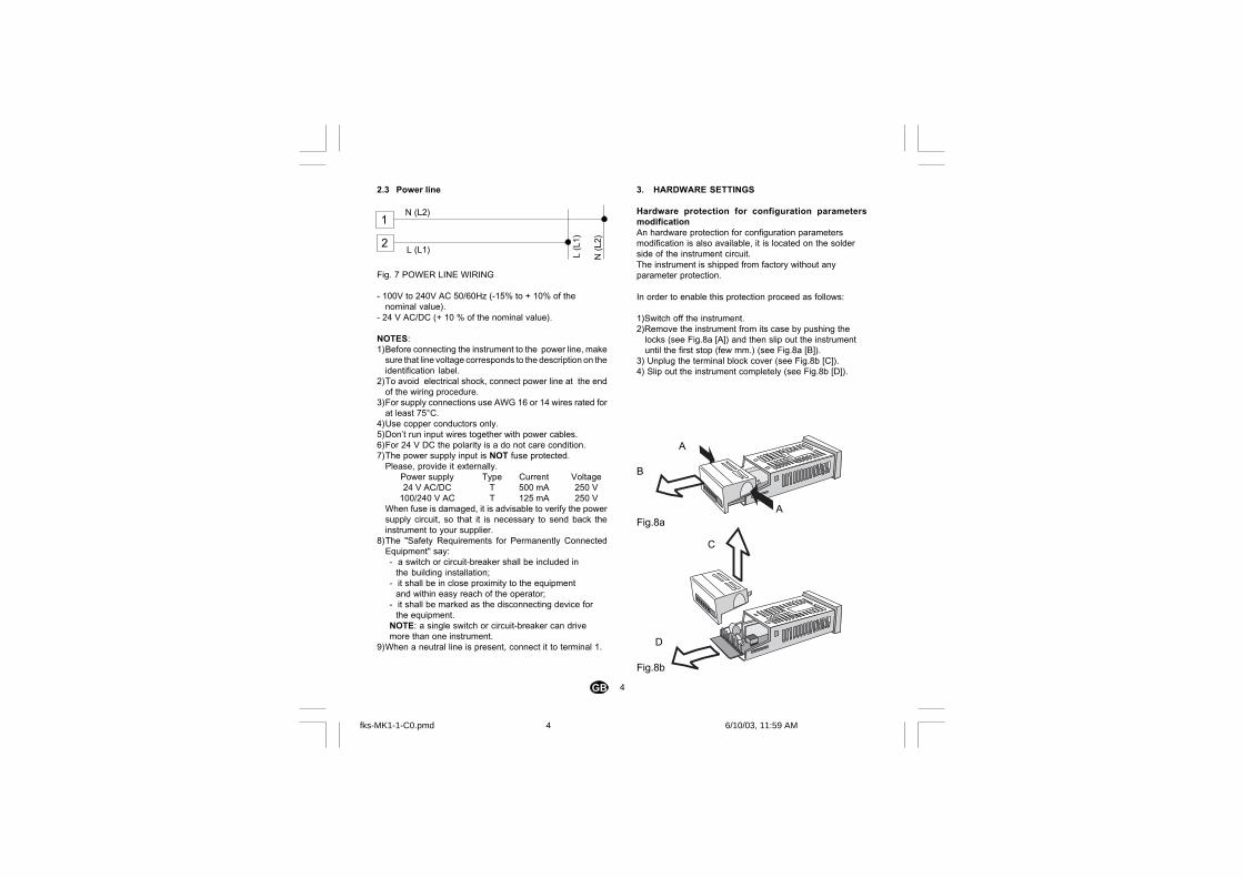
2.3 Power line
Fig. 7 POWER LINE WIRING
- 100V to 240V AC 50/60Hz (-15% to + 10% of thenominal value).
- 24 V AC/DC (+ 10 % of the nominal value).
NOTES:1)Before connecting the instrument to the power line, make
sure that line voltage corresponds to the description on theidentification label.
2)To avoid electrical shock, connect power line at the endof the wiring procedure.
3)For supply connections use AWG 16 or 14 wires rated forat least 75°C.
4)Use copper conductors only.5)Don’t run input wires together with power cables.6)For 24 V DC the polarity is a do not care condition.7)The power supply input is NOT fuse protected.
Please, provide it externally.Power supply Type Current Voltage24 V AC/DC T 500 mA 250 V
100/240 V AC T 125 mA 250 VWhen fuse is damaged, it is advisable to verify the powersupply circuit, so that it is necessary to send back theinstrument to your supplier.
8)The "Safety Requirements for Permanently ConnectedEquipment" say:- a switch or circuit-breaker shall be included in
the building installation;- it shall be in close proximity to the equipment
and within easy reach of the operator;- it shall be marked as the disconnecting device for
the equipment.NOTE: a single switch or circuit-breaker can drivemore than one instrument.
9)When a neutral line is present, connect it to terminal 1.
3. HARDWARE SETTINGS
Hardware protection for configuration parametersmodificationAn hardware protection for configuration parametersmodification is also available, it is located on the solderside of the instrument circuit.The instrument is shipped from factory without anyparameter protection.
In order to enable this protection proceed as follows:
1)Switch off the instrument.2)Remove the instrument from its case by pushing the
locks (see Fig.8a [A]) and then slip out the instrumentuntil the first stop (few mm.) (see Fig.8a [B]).
3) Unplug the terminal block cover (see Fig.8b [C]).4) Slip out the instrument completely (see Fig.8b [D]).
2
1N (L2)
L (L1)
N (L
2)
L (L
1)
Fig.8b
Fig.8a
A
A
B
C
D
fks-MK1-1-C0.pmd 6/10/03, 11:59 AM4

5GB
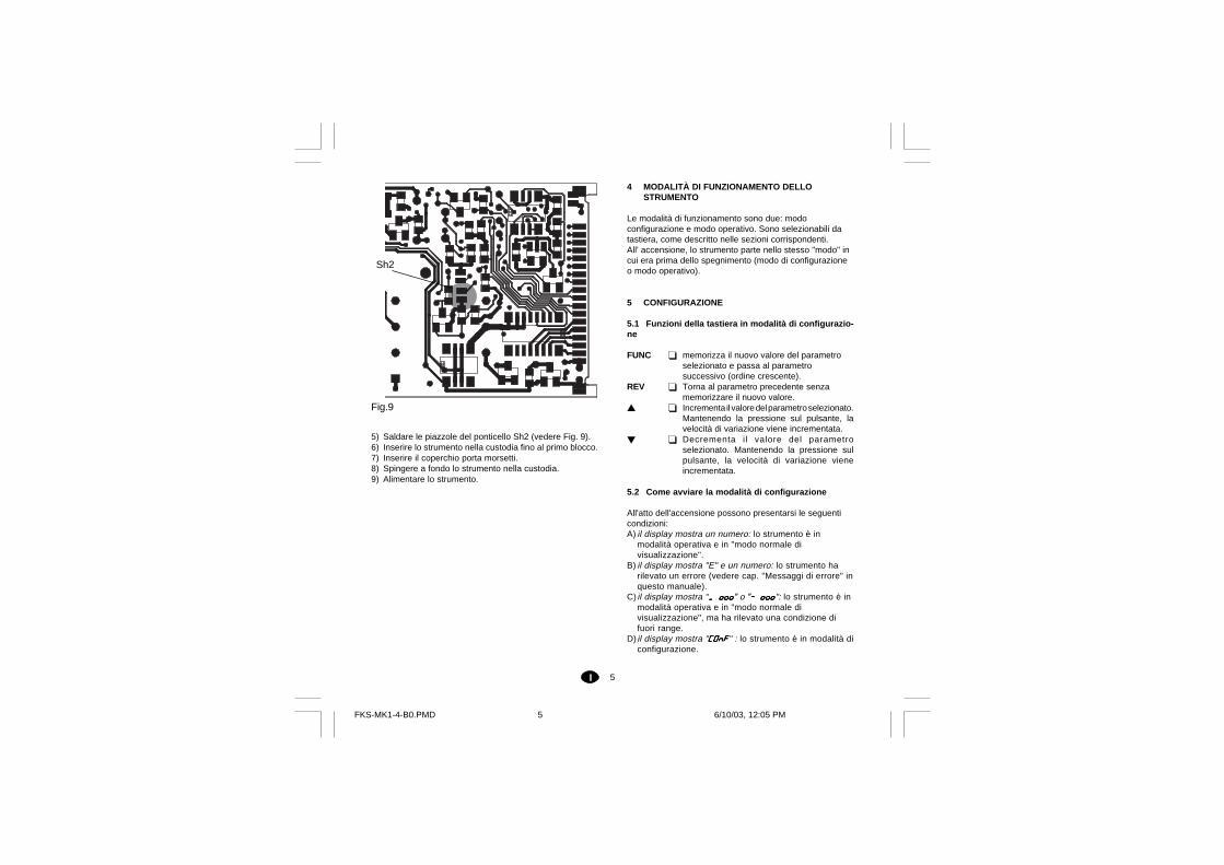
5) Solder the Sh2 pads (See Fig. 9).6) Re-insert until the first stop the instrument into the case.7) Plug-in the terminal block cover.8) Push the instrument completely into the case.9) Switch on the instrument.
Fig.9
Sh2
4 THE INSTRUMENT MODE OF WORKING
The instrument can be operative in two different modes:configuration mode and operating mode. They can beselected from the keyboard, as described in thecorresponding sections.On switching on, the instrument starts in the “mode” it wasin before switching off (configuration mode or operatingmode).
5 CONFIGURATION
5.1 Keyboard functions during configuration mode
FUNC it saves the new value of the parameterselected and goes to the next parameter(increasing order).
REV it allows to scroll back the parameters withoutmemorizing the new setting.
Increases the value of the selectedparameter. Keeping the pushbutton pressed,the variation speed is increased.
Decreases the value of the selectedparameter.Keeping the pushbutton pressed, thevariation speed is increased.
5.2 How to start the configuration mode
On switching on, fore conditions can be shown:A) the display shows a number: the instrument is in
operative mode and in "normal display mode".B) the display shows "E." and a number: the instrument
have detected an error (see chapter "errormessages" in this manual).
C) the display shows "_ ooo ooo ooo ooo ooo" or "- ooooooooooooooo": the instrumentis in operative mode and in "normal display mode" butan out of range condition is detected.
D) the display shows "CONFCONFCONFCONFCONF" : the instrument is inconfiguration mode.
fks-MK1-1-C0.pmd 6/10/03, 11:59 AM5
6GB
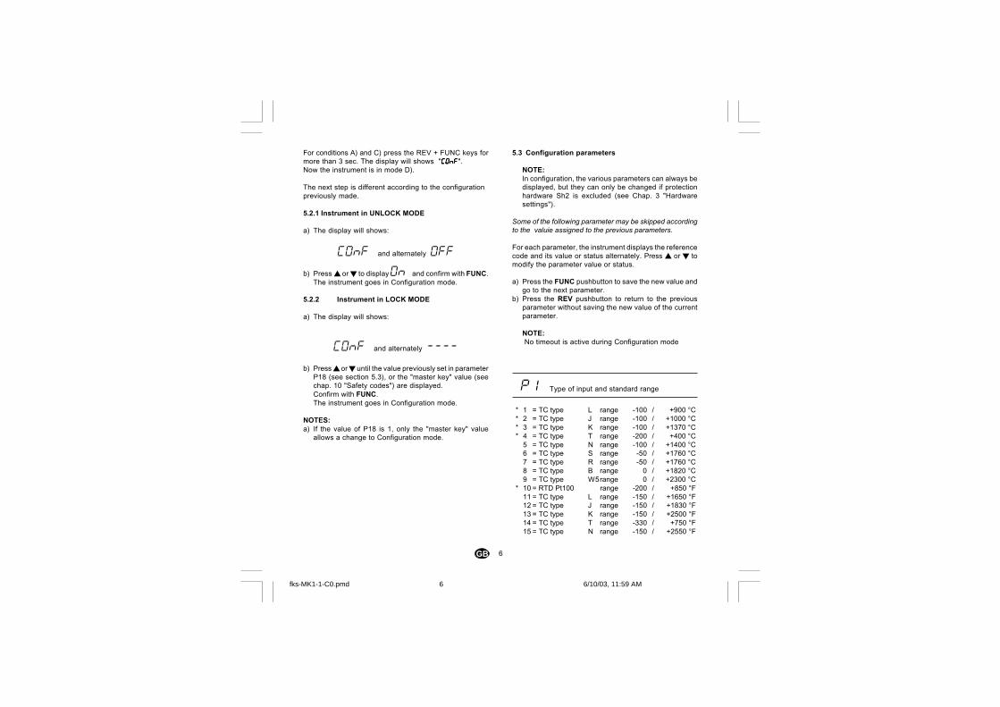
5.3 Configuration parameters
NOTE:In configuration, the various parameters can always bedisplayed, but they can only be changed if protectionhardware Sh2 is excluded (see Chap. 3 "Hardwaresettings").
Some of the following parameter may be skipped accordingto the valuie assigned to the previous parameters.
For each parameter, the instrument displays the referencecode and its value or status alternately. Press ortomodify the parameter value or status.
a) Press the FUNC pushbutton to save the new value andgo to the next parameter.
b) Press the REV pushbutton to return to the previousparameter without saving the new value of the currentparameter.
NOTE: No timeout is active during Configuration mode
P1 Type of input and standard range
* 1 = TC type L range -100 / +900 °C* 2 = TC type J range -100 / +1000 °C* 3 = TC type K range -100 / +1370 °C* 4 = TC type T range -200 / +400 °C
5 = TC type N range -100 / +1400 °C6 = TC type S range -50 / +1760 °C7 = TC type R range -50 / +1760 °C8 = TC type B range 0 / +1820 °C9 = TC type W5range 0 / +2300 °C
* 10 = RTD Pt100 range -200 / +850 °F11 = TC type L range -150 / +1650 °F12 = TC type J range -150 / +1830 °F13 = TC type K range -150 / +2500 °F14 = TC type T range -330 / +750 °F15 = TC type N range -150 / +2550 °F
For conditions A) and C) press the REV + FUNC keys formore than 3 sec. The display will shows "CONFCONFCONFCONFCONF".Now the instrument is in mode D).
The next step is different according to the configurationpreviously made.
5.2.1 Instrument in UNLOCK MODE
a) The display will shows:
CONF and alternately OFF
b) Press orto display ON and confirm with FUNC.The instrument goes in Configuration mode.
5.2.2 Instrument in LOCK MODE
a) The display will shows:
CONF and alternately ----
b) Press oruntil the value previously set in parameterP18 (see section 5.3), or the "master key" value (seechap. 10 "Safety codes") are displayed.Confirm with FUNC.The instrument goes in Configuration mode.
NOTES:a) If the value of P18 is 1, only the "master key" value
allows a change to Configuration mode.
fks-MK1-1-C0.pmd 6/10/03, 11:59 AM6
7GB
16 = TC type S range -60 / +3200 °F17 = TC type R range 0 / +3200 °F18 = TC type B range 32 / +3300 °F19 = TC type W5range 0 / +4170 °F
* 20 = RTD Pt100 range -330 / +1560 °F21 = Linear range 0 / 60 mV22 = Linear range 12 / 60 mV
* For these ranges it is possible to select a readout withone decimal figure, in this case the instrument cannotdisplay a measure lower than -199.9 or higher than999.9 and the input range will be limited by it.
NOTE:If the type of input is modified, the instrument willautomatically force:- parameter "P3" to the new initial scale value (0 for
linear inputs),- parameter "P4" to the new full scale value (4000 for
linear inputs),- parameter "P16" to the new initial scale value,- parameter "P2" to "no decimal figure".
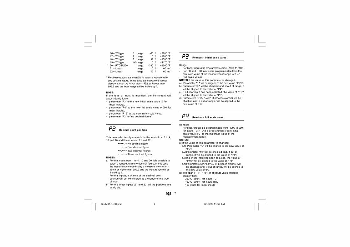
P2P2P2P2P2 Decimal point position
This parameter is only available for the inputs from 1 to 4,10 and 20 and linear inputs 21 and 22.
----. = No decimal figure.---.- = One decimal figure.--.-- = Two decimal figures.-.--- = Three decimal figures.
NOTES:a) For the inputs from 1 to 4, 10 and 20, it is possible to
select a readout with one decimal figure, in this casethe instrument cannot display a measure lower than -199.9 or higher than 999.9 and the input range will belimited by it.For this inputs, a chance of the decimal pointposition will be considered as a change of the typeof input.
b) For the linear inputs (21 and 22) all the positions areavailable.
P3P3P3P3P3 Readout - initial scale value
Range:- For linear inputs it is programmable from -1999 to 9999.- For TC and RTD inputs it is programmable from the
minimum value of the measurement range to "P4"(full scale value).
NOTES:If the value of this parameter is changed,a) Parameter "rL" will be aligned to the new value of "P3";b) Parameter "rH" will be checked and, if out of range, it
will be aligned to the value of "P4";c) If a linear input has been selected, the value of "P16"
will be aligned to the value of "P3".d) Parameters SP/AL1/AL2 (if process alarms) will be
checked and, if out of range, will be aligned to thenew value of "P3.
P4P4P4P4P4 Readout - full scale value
Ranges:- For linear inputs it is programmable from -1999 to 999.- for inputs TC/RTD it is programmable from initial
scale value (P3) to the maximum value of themeasurement range.
NOTES:a) If the value of this parameter is changed,
a.1) Parameter "rL" will be aligned to the new value of"P3";
a.2)Parameter "rH" will be checked and, if out ofrange, it will be aligned to the value of "P4";
a.3)If a linear input has been selected, the value of"P16" will be aligned to the value of "P3".
a.4)Parameters SP/AL1/AL2 (if process alarms) willbe checked and, if out of range, will be aligned tothe new value of "P3.
B) The span ("P4" - "P3"), in absolute value, must begreater than:- 300°C (550°F) for inputs TC- 100°C (200°F) for inputs RTD- 100 digits for linear inputs
fks-MK1-1-C0.pmd 6/10/03, 11:59 AM7
8GB
NOTES:a) If "rEV" has been selected and "P10" (function of output
2) is different from "CooL":1 "P53", if less than zero, is forced to zero.2 "OLH", if less than or equal to zero, is forced to 100.3 "OLL", if less than zero, is forced to zero.4 "IP" is forced to 50.
b) If "dir" has been selected:1 "P10", if equal to "CooL", is forced to "nonE"2 "P53", if less than zero, is forced to zero.3 "OLH", if less than or equal to zero, is forced to 100.4 "OLL", if less than zero, is forced to zero.5 "IP" is forced to 50.
c) If the output for alarm 1 ("ALr.1") has been selected:1 "P10", if set to "bAnd","dEV" or "CooL", is forced to
"nonE"2 "P56" is forced to "nonE"3 The threshold of "AL.1" is checked and, if out of
range, aligned to "P3".
NOTE: setting "P6" as alarm output, the instrumentbecomes an indicator and all the configuration andoperative parameters (e.g. SP, PB, TI, etc.) relatedwith PID control will be skipped.
P7P7P7P7P7 Alarm 1: operating mode
This parameter is only available if output 1 is configured asalarm 1 ("P6" = "ALr.1")
Range: H.A. = High alarm with automatic resetL.A. = Low alarm with automatic resetH.L. = High alarm with manual reset (latched
alarm)L.L. = Low alarm with manual reset (latched
alarm)
For linear inputs, the span will be checked at the end ofconfigurationprocedure. If it will be wrong, error code"E204" will be displayed. To end the configurationprocedure correct the wrong value.
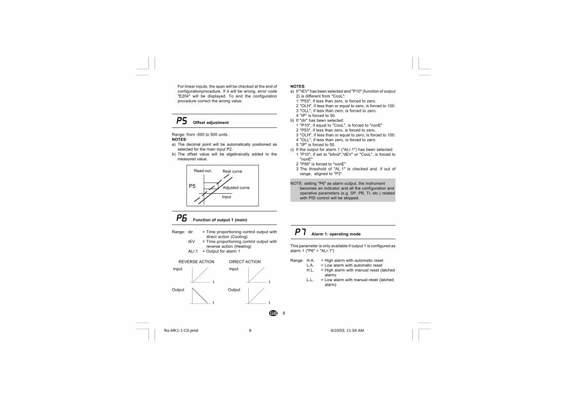
P5P5P5P5P5 Offset adjustment
Range: from -500 to 500 units.NOTES:a) The decimal point will be automatically positioned as
selected for the main input P2.b) The offset value will be algebraically added to the
measured value.
P6P6P6P6P6 Function of output 1 (main)
Range: dir = Time proportioning control output withdirect action (Cooling)
rEV = Time proportioning control output withreverse action (Heating)
ALr.1 = Output for alarm 1
REVERSE ACTION DIRECT ACTION
t
Input
t
Output
t
Input
t
Output
Real curveRead-out.
Adjusted curve
Input
P5
fks-MK1-1-C0.pmd 6/10/03, 11:59 AM8
9GB
P8P8P8P8P8 Alarm 1: action
This parameter is only available if output 1 is configured asalarm 1 ("P6" = "ALr.1")
Range: dir = direct action (the relay is energized orSSr=1 in alarm condition)
rEV = reverse action (the relay is de-energizedor SSr=0 in alarm condition)
P9P9P9P9P9 Alarm 1: standby function
This parameter is only available if output 1 is configured asalarm 1 ("P6" = "ALr.1")
Range: OFF = standby function disabledON = standby function enabled
NOTE:- The standby function can "mask" an alarm condition
on switching on, until the process variable reachesthe alarm threshold plus or minus the hysteresis.
P10P10P10P10P10 Function of output 2 (secondary)
Range: nonE = Output not usednALF = Output to signal a fault condition
detected on the measurementProc = Alarm 2 output - Process alarmbAnd = Alarm 2 output - Band alarmdEV = Alarm 2 output - Deviation alarmCooL = Output used for the cooling in the
configuration with two control outputs.NOTES:a) If "bAnd" or "dEV" have been selected, parameter "P6"
is forced to "rEV" if "ALr.1" is set.b) If a type of alarm is selected, threshold "AL.2" is
checked and, if out of range, forced to the default value.
c) Setting "P10" equal to "CooL":1 "P6" will be forced to "rEV".2 "OLL" will be forced to -100 and "OLH", if smaller
than or equal to zero, will be forced to 100.3 "IP" will be forced to zero.
d) If output "CooL" is removed, the instrument performsthe action described in parameter "P6" (note a).
P1P1P1P1P11 1 1 1 1 Type of cooling media or operating mode alarm
2
This parameter is only available if "P10" is different from"nonE".
When "P10" is different from "CooL":Range: H.A. = High alarm (outside for band alarm) with
automatic reset.L.A. = Low alarm (inside for band alarm) with
automatic reset.H.L. = High alarm (outside for band alarm)
with manual reset.L.L. = Low alarm (inside for band alarm) with
manual resetNOTE: The "high or low" selection has no effect if
the output is used as fault signaller.
When "P10" is equal to "CooL":Range: If "P10" is set to "CooL":
Air = The cooling media is airOIL = The cooling media is oilH2O = The cooling media is water.
NOTE:- Varying the type of cooling, parameters "C2" and "rC" will
be forced to the relative default values.
fks-MK1-1-C0.pmd 6/10/03, 11:59 AM9
10GB
P14P14P14P14P14 SMART function
This parameter is available only when at least one controloutput is configured.Range: dIS = Smart function disabled.
Enb = Smart function enabled (activating/deactivating the function is not subjectto the parameter protection rule).
Enb.P = Smart function enabled (activating/deactivating the function is subject to theparameter protection rule).
P15P15P15P15P15 Type of control action
This parameter is available only when at least one controloutput is configured.Range: Pid = The process is controlled by PIDaction.
Pi = The process is controlled by PI action.NOTE: - if the control action type was changed (parameter "P15")
and the configuration procedure has been enabled whilethe second part of the SMARTalgorithm (ADAPTIVE) wasin progress, the "Pb" and "ti" parameters will be updatedwith the values calculated by the first part (TUNE) of theSMART for the new type of control action.If these values are incorrect:- The "E.120" error message will be displayed for
2 seconds;- parameters "Pb" and "ti" will not be updated;- the instrument will work with a PI control action
(parameter "td" will be forced to 0).In this situation the SMART function should be startedagain.
P12P12P12P12P12 Alarm 2: action
This parameter is only available if the function of output 2is configured as alarm 2 ("P10" different from "nonE" or"CooL").
Range: dir = direct action (the relay is energized orSSr=1 in alarm condition)
rEV = reverse action (the relay is de-energixedor SSr=0 in alarm condition)
NOTE:- If LBA is enabled on output 2 ("P56" = "Out2", see
"Addendum" manual), the same selection is set on "P61".
P13P13P13P13P13 Alarm 2: standby function
This parameter is only available if the function of output 2is configured as alarm 2 ("P10" different from "nonE","nALF", "CooL").
Range: OFF = standby function disabledON = standby function enabled
NOTE:- The standby function can "mask" an alarm condition at
the start up (if the alarm is programmed as processalarm), or at the start up and after a set point change(if the alarm is programmed as band or deviation), untilthe process variable reaches the alarm threshold plusor minus the hysteresis.
fks-MK1-1-C0.pmd 6/10/03, 11:59 AM10
11GB
P16P16P16P16P16 Input threshold to enable Soft Start
This parameter is available if at least one control output hasbeen configured.
Range: - between the range limits of TC/RTD (see "P1")- between the limits of "P3" and "P4" for linear
inputs
P17P17P17P17P17 Timeout selection
This parameter allows to set the time duration of thetimeout used by the instrument during the parametermodification in operating mode.Range: tn.10 = timeout 10 sec
tn.30 = timeout 30 sec
P18P18P18P18P18 Safety code
Range: 0 = No protection. The device is always inUNLOCK condition and all the operatingparameters can always be modified
1 = Total protection. The device is always inLOCK condition and no operating parameter(with the exception of parameters "SP" and"n.rST") can be modified
2/4999 = Code to enable/disable the protection of theoperating parameters (See "nnn")(Parameters "SP" and "n.rST" are NOT subjectto protection).
5000/9999 = Code to enable/disable the protectionof the operating parameters (See "nnn").Parameters "SP","n.rST", "AL.1" and "AL.2",are NOT subject to protection.
THE LOCKED PARAMETERS WILL NOT BE DISPLAYED
NOTES:a) To enable/disable the SMART algorithm see also "P14"b) When a numerical code is selected, it will no longer be
displayed (the display will show "2"). If the code isforgotten a new one must be set.
The basic configuration of the instrument is ended, and thedisplay shows:
C.EndPress FUNC to return to the start of the configuration.
COnFTo go to operating mode press REV + FUNC for 3 seconds.
NOTE:The "Addendum " manual gives the programming of theparameters from "P51" to "P66".
fks-MK1-1-C0.pmd 6/10/03, 11:59 AM11
12GB
Increases the value of the selectedparameter. Keeping the pushbuttonpressed, the variation speed is increased.
Decreases the value of the selectedparameter. Keeping the pushbuttonpressed, the variation speed is increased.
+ When the instrument is in "normal displaymode", reload the default values of theoperative parameters (see chap. 10"Default parameters")
REV + FUNC When the instrument is in "normal display
mode", if pressed for more than 3 sec.,switches from the configuration procedureto the operating procedure or vice versa.
NOTE:During operative mode, a timeout of 10 or 30seconds (see parameter "P17" in "Configuration") isapplied to the parameters modification.If when modifying a parameter, no pushbutton ispressed for a time longer than the timeout (10 or 30seconds), the instrument automatically returns to"normal display mode" losing any modification of thelast parameter selected.
6.2 Alternative displays
From the normal display mode, it is possible to change theinformation shown on the display in the following way:a) On pressing the FUNC key for more than 3 sec., the
display will show the status of alarm LBA (if configured) asfollows:"L.b.OF" = no allarm"L.b.AL" = alarm condition
b) On pressing the FUNC key again the display will show theset point value. The decimal point indicated in Fig. 10 isON.
Fig. 10 Control output value Set point
6 OPERATING MODE
During the operating mode the instrument performs thecontrol loop and manages all the functions (SMART,alarms, etc...).At instrument power on in operative mode, the displayshows the measured value (we define this condition as“normal display mode”).On switching on the instrument starts in the "mode" it wasin before switching off.If it starts in Configuration mode, press REV+FUNC for 3seconds. The instrument will be resetted and it will startedagain in operating mode.
6.1 Keyboard functions during operative mode
All the actions above explained which require the pressureof two or more keys must follow exactly the keys equenceshown.
FUNC During the parameter modificationprocedure, saves the new value of theparameter selected and goes to the nextparameter (increasing order).
When the instrument is in "normal displaymode", if pressed for more than 3 sec.,changes the display indication (see"Alternative display functions". Sect. 6.2).
REV During parameter modification, it allows toscroll back the parameters withoutmemorizing the new setting.
When the instrument is in “normal displaymode”, if pressed for more than 3 sec.starts/stops the SMART function (seesection 6.8).
+ FUNC When the instrument is in “normal display
mode”, if pressed for more than 3 sec.disables/disables the control output (see"Enabling / Disabling the control output"section 6.6).
+ FUNC When the instrument is in “normal display
mode”, enables the Lamp Test function(see “Lamp Test”, section. 7.1).
fks-MK1-1-C0.pmd 6/10/03, 12:03 PM12
13GB
c) Push FUNC key again, the display will show the controloutput value, the two points as shown in Fig 10 are lit.The value of the MAIN control output is shown on thetwo most significant digits, while the value of theSECONDARY control output is shown on the two leastsignificant digits.NOTES:1) The graphic symbol " "shows that the respective
output value is 100%.2) If the control output is disabled the display will show
OFF.
NOTES:a) The alternative displays are bound to the time out .To
remove the timeout press or.b) When the LBA alarm is detected the indication described
at point a) is automatically forced. In this case the type ofdisplay is not subject to timeout.
6.3 Indicators (beacons)
There are three luminous indicators on the left side of thedisplay.
ST Flashes when the first phase of the SMART algorithmis working (TUNE).ON when the second phase of the SMART algorithmis working (ADAPTIVE)
1 ON when output 1, used as control output, is ON, orwhen alarm 1 is in alarm state.
2 ON when output 2, used as control output, is ON, orwhen alarm 2 is in alarm state
6.4 How to check or modify the operative parameters
When the instrument is in normal display mode check ormodify the operating parameters as follows:1) Press the FUNC key to advance the parameters (REV to
go backwards); the display will show the mnemonic codeof the parameter and its value (or state) alternately.
2) To vary the value or the state, press the or keys (inthe case of a numerical value press to increase, todecrease).
3) Press the FUNC key to save the new value (or the newstate) and go to the next parameter. Press REV to displaythe previous parameter without saving the new value.
4) One can quit the modification/check of the operatingparameters:- automatically, after the timeout (see note c)- manually, pressing the FUNC. key several times.
NOTES:a) In relation to the instrument configuration, a few
parameters may not be displayed.b) With the exception of the set point and the alarms
("SP","n.rST", "AL.1" and "AL.2", see "P18" in section5.2), the remaining parameters can only be modifiedwhen the protection is excluded.The locked parameters are not displayed.
c) Checking and modifying the parameters are subject totimeout (see "P17" in section 5.2). When this time haselapsed, the instrument will return to the "normal displaymode" and any modifications of the last parameterdisplayed will be lost.
6.5 Operating parameters
SPSPSPSPSP Set Point
This parameter is available if at least one control output hasbeen configured.Range: da rL a rH
n.rStn.rStn.rStn.rStn.rSt Manual alarm reset
This parameter is available if at least one alarm has themanual reset function.Range: On = function active
OFF = no actionNOTE:- To reset the alarm condition select ON then press FUNC.
fks-MK1-1-C0.pmd 6/10/03, 12:00 PM13
14GB
AL.2AL.2AL.2AL.2AL.2 Threshold alarm 2
This parameter is only available if output 2 is configured asalarm ("P10" = "Proc", "bAnd" or "dEV", see section 5.2).Range: - from "P3" to "P4" if process alarm ("Proc")
- from 0 to 1000 if range alarm ("bAnd")- from -1000 to 1000 if deviation alarm ("dEV")
HSA.2HSA.2HSA.2HSA.2HSA.2 Hysteresis alarm 2
This parameter is only available if output 2 is configured asalarm ("P10" = "Proc", "bAnd" or "dEV", see section 5.2).Range: from 1 to 200 unitsNOTE:- If "P10" is programmed as band alarm, the hysteresis
is limited by the threshold value set in the previouspoint.
PBPBPBPBPB Proportional range
This parameter is available when at least one control outputis configured.Range: from 1.0% to 100.0% of the input span ("P4" - "P3).Set 0.0% for On/OFF control action
NOTES:a) The Pb resolution will be equal to 0.1% up to 10.0% and
1% from 10.0% up to 100.0%.b) When the instrument uses the SMART algorithm, the
value of "Pb" will be limited as selected by parameters"P62" and "P63" (see "Addendum").
nnnnnnnnnnnnnnn Software key
This parameter is available if "P18" is equal to or greater than2 (see sect. 5.2).Range: from 2 to 9999. Enter the code assigned and
press the FUNC key.
NOTE:- At first the parameter protection state will appear on the
display.On Protection activatedOFF Protection deactivatedSet the value assigned to "P18" to deactivate theprotection, set a different value to activate it.
AL.1AL.1AL.1AL.1AL.1 Threshold alarm 1
This parameter is only available if output 1 is configured asalarm ("P6" = "ALr.1", see section 5.2).
Range: - from "P3" to "P4".
HSA.1HSA.1HSA.1HSA.1HSA.1 Hysteresis alarm 1
This parameter is only available if output 1 is configured asalarm ("P6" = "ALr.1", see section 5.2).Range: from 1 to 200 digits
fks-MK1-1-C0.pmd 6/10/03, 12:00 PM14
15GB
HysHysHysHysHys Hysteresis (for ON/OFF check)
This parameter is available when at least one control outputis configured and Pb =0 (check On/OFF)Range: from 0.1% to 10.0% of the input span ("P3" / "P4").
tititititi Integral time
This parameter is available when at least one control outputis configured and Pb is different from 0.Range: from 00.01 to 20.00 mm.ss
Beyond this value the display goes dark (with theexception of the decimal point) and the integralaction is excluded.
NOTE:- When the instrument uses the SMART algorithm, the
value of "ti" will be limited as selected by parameters"P64" and "P65" (see "Addendum").
tdtdtdtdtd Derivative action time
This parameter is available when at least one control outputis configured, "P15" is equal to "Pid" and "Pb" is differentfrom 0.Range: From 00.00 to 10.00 mm.ssNOTE:
When the instrument uses the SMART algorithm, "td" willbe proportional to the value of "ti", in agreement with whatwas calculated by TUNE
IPIPIPIPIP Pre-load of the integral action
This parameter is available when at least one control outputis configured and Pb is different from 0.Range:- from 0 to 100 % of the output when the instrument is
configured with one control output.- from -100 to 100 % of the output when the instrument
isconfigured with two control outputs.
CCCCC Main output cycle time
This parameter is available if output 1 is configured ascontrol output.Range: from 1 to 200 sec.
C2C2C2C2C2 Secondary output cycle time
This parameter is available if output 2 is configured ascontrol output.Range: from 1 to 200 sec.
rCrCrCrCrC Second output relative gain.
This parameter is available if output 2 is configured ascontrol output.Range: from 0.20 to 1.00NOTE:- When the instrument uses the SMART algorithm and
"P66"= ON, the value of rC is limited in relation to the typeof cooling media used ("P11", see sect. 5.2):0.85 - 1.00 if air0.80 - 0,90 if oil0.30 - 0.60 if water
fks-MK1-1-C0.pmd 6/10/03, 12:00 PM15
16GB
OLHOLHOLHOLHOLH Control output high limit
This parameter is available when at least one control outputis configured.Range: from OLL to 100.
tOLtOLtOLtOLtOL Duration of the soft start function
This parameter is available when at least one output isconfigured as control output.Range: from 1 to 540 min.Beyond this value, the display indicates "InF" and the limitingaction will always be active independent of the threshold setwith "P16".NOTE: The tOL can be always modified but:- if the new value is set from 1 to 540, it will be activated only
at the next instrument power up or when the instrument isreverted from the output power off;
- if "InF" is set, it will be immediately activated.
OLAPOLAPOLAPOLAPOLAP Overlap/dead band between the mainoutput and the secondary output
This parameter is available if output 2 is configured ascontrol output.Range: from -20 to 50NOTE: A negative value means a dead band while a positivevalue means an overlap.
rLrLrLrLrL Lower set point limit
This parameter is available when at least one control outputis configured.Range: from "P3" to rH.NOTE: if "rL" is modified and its new value is greater than theset point value ("SP"), the value of SP will be realigned to"rL".
rHrHrHrHrH Upper set point limit
This parameter is available when at least one control outputis configured.Range: from "rL" to "P4".NOTE: if "rH" s modified and its new value is less than thevalue of SP, the value of SP will be realigned to "rH".
OLLOLLOLLOLLOLL Control output low limit
This parameter is available when at least one control outputis configured.Range: from 0 to OLH if the instrument is configured with
one control output.from -100 to OLH if the instrument is configuredwith two control outputs.
fks-MK1-1-C0.pmd 6/10/03, 12:00 PM16
17GB
6.6 Enabling/disabling the control output
When the control output is disabled, all the controloutputs and the alarms will go to OFF state and theinstrument will operate as a simple indicator displayingthe value measured.To enable/disable the control output press the + FUNCpushbuttons for more than 3 sec. when the instrument isin the "normal display mode".The enabling/disabling command is not subject to theoperating parameter protection rule.During the output power off all the display functions areavailable (the display will show "OFF" if the control outputvalue is required.).
The alarms ( if configured) will not be operative
At power up, the control output will remain disabled if apower down is occurred.When the control output is enabled again, all the functionswill be activated as for switching on the instrument.
6.7 Direct modification of the set point
When the instrument is in the "normal display mode" andat least one control output has been configured,modification of the set point can be accessed directly.On pressing the or keys for more than 2 s, the setpoint will appear (the decimal point to the right of the lesssignificant figure will be ON) and its value will start tochange.The new set point value will be operating 2 seconds afterthe last pressing of the keys. The display will display thevalue measured again.
6.8 SMART function
Can automatically optimise the control output. Thefunction has two algorithms, defined TUNE andADAPTIVE. The first calculate the parameters when theprocess starts. During this phase, the control outputvaries from maximum output value to 0, and vice versa.The instrument can be put in TUNE mode at any time.The correct parameters are automatically calculated afterthere have been two successive peaks.The ADAPTIVE function is used to re-obtimise the PIDparameters if the process characteristics changes.The ADAPTIVE algorithm starts automatically after the"TUNE". If it is not necessary, it is possible to deactivatethe smart function at the end of the TUNE.
To enable/disable the smart function, press the REV keyfor more than 3 sec., when the instrument is in the"normal display mode". The action can be proteced or not(see "P14")The LED ST will flash during the first phase of the SMART(TUNE) algorithm, while it will be ON steadily during thesecond phase (ADAPTIVE).
When the SMART function is enabled, the controlparameters can be displayed but not modified.
NOTE:- the SMART function cannot be activated when:- the ON/OFF check is set (Pb=0);- the control output is disabled;- the SMART function has not been configured.
fks-MK1-1-C0.pmd 6/10/03, 12:00 PM17
18GB
8 ERROR MESSAGES
8.1 Indication of out of range and/or sensor breaks
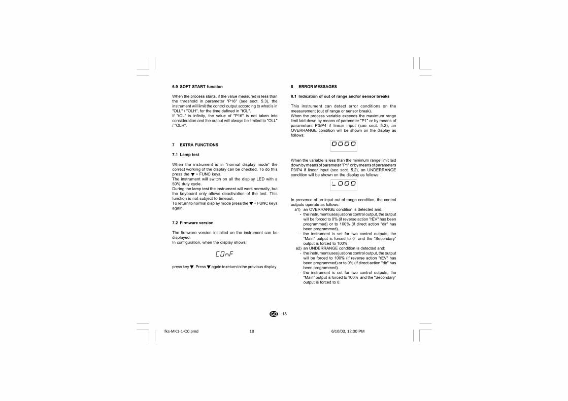
This instrument can detect error conditions on themeasurement (out of range or sensor break).When the process variable exceeds the maximum rangelimit laid down by means of parameter "P1" or by means ofparameters P3/P4 if linear input (see sect. 5.2), anOVERRANGE condition will be shown on the display asfollows:
When the variable is less than the minimum range limit laiddown by means of parameter "P1" or by means of parametersP3/P4 if linear input (see sect. 5.2), an UNDERRANGEcondition will be shown on the display as follows:
In presence of an input out-of-range condition, the controloutputs operate as follows:
a1) an OVERRANGE condition is detected and:- the instrument uses just one control output, the output
will be forced to 0% (if reverse action "rEV" has beenprogrammed) or to 100% (if direct action "dir" hasbeen programmed).
- the instrument is set for two control outputs, the“Main” output is forced to 0 and the “Secondary”output is forced to 100%.
a2) an UNDERRANGE condition is detected and:- the instrument uses just one control output, the output
will be forced to 100% (if reverse action "rEV" hasbeen programmed) or to 0% (if direct action "dir" hasbeen programmed).
- the instrument is set for two control outputs, the“Main” output is forced to 100% and the “Secondary”output is forced to 0.
6.9 SOFT START function
When the process starts, if the value measured is less thanthe threshold in parameter "P16" (see sect. 5.3), theinstrument will limit the control output according to what is in"OLL" / "OLH", for the time defined in "tOL".If "tOL" is infinity, the value of "P16" is not taken intoconsideration and the output will always be limited to "OLL"/ "OLH".
7 EXTRA FUNCTIONS
7.1 Lamp test
When the instrument is in “normal display mode” thecorrect working of the display can be checked. To do thispress the + FUNC keys.The instrument will switch on all the display LED with a50% duty cycle.During the lamp test the instrument will work normally, butthe keyboard only allows deactivation of the test. Thisfunction is not subject to timeout.To return to normal display mode press the + FUNC keysagain.
7.2 Firmware version
The firmware version installed on the instrument can bedisplayed.In configuration, when the display shows:
CONF
press key. Press again to return to the previous display.
fks-MK1-1-C0.pmd 6/10/03, 12:00 PM18

19GB
This instrument is capable to detect the sensor leads breakcondition. When the sensor leads break condition is detected,the instrument shows:
OPEnNOTE:for the RTD inputs, by means of a special test, the followingmessage is given:
Shrtwhen input resistance is less than 12 Ω (Short circuit sensordetection).The instrument is also capable to detect a reference junctionmeasurement error (E.502) and on the internal auto-zero(E.500).When a fault condition different from overrange or underrangeis detected, alarms and control output will operate as inpresence of an overrange condition.The error messages are given on AL2 (if configured).
8.2 Error list
On switching on in the operating mode, all the parametersare checked.If the instrument detects an error, an identification code isshown, like the one below:
E.201The instrument performs a automatic reset after a timeout of3 sec.
E.2xx Configuration parameter error. The last twosignificant figures indicate the number of thewrong parameter.When one of these errors is detected, pressREV + FUNC to go to Configuration mode andcorrect the value.
E.400 Operating parameter error. When it is detected,press + continuously to load the defaultvalues of the operative parameters and thanremake the operative parameter settingprocedure.
Some errors which can be displayed:
E.100 Error while saving the data in EEpromE.120 Error on control parameters calculated by SMART
when the control action was changed from PI toPID or viceversa.
E.130 Error during the SMART. The algorithm cannotcalculate the adjustment parameters correctly. Theinstrument will be forced to work with the PI controlaction.
E.140 Error in the adjustment parameters calculated bythe SMART (ADAPTIVE algorithm). The valuesare out of the range set in "P62", "P63", "P64" and"P65" (see "Addendum")
NOTE:push any key to delete E.130 or E.140 indication.
fks-MK1-1-C0.pmd 6/10/03, 12:00 PM19
20GB
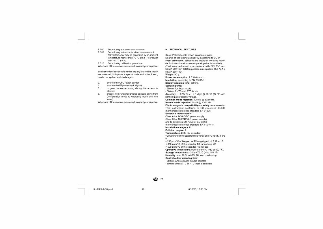
9 TECHNICAL FEATURES
Case: Polycarbonate brown transparent color.Degree of self-extinguishing: V2 according to UL 94Front protection - designed and tested for IP 65 and NEMA4X for indoor locations (when panel gasket is installed).(Test were performed in accordance with CEI 70-1 andNEMA 250-1991 STD).n accordo agli standard CEI 70-1 eNEMA 250-1991)Weight: 90 g.Power consumption: 2.5 Watts max.Insulation: according to EN 61010-1Display updating time: 500 ms.Sampling time:- 250 ms for linear inputs- 500 ms for TC and RTD inputs.Accuracy: + 0,2% f.s.v. + 1 digit @ 25 °C (77 °F) andnominal power supply voltage.Common mode rejection: 120 dB @ 50/60 Hz.Normal mode rejection: 60 dB @ 50/60 Hz.Electromagnetic compatibility and safety requirements:This instrument conforms to EU directives 89/336(harmonised reference standard EN 61326Emission requirements:Class A for 24VAC/DC power supplyClass B for 100/240VAC power supply)and to directives EU 73/23 or EU 93/68(harmonised reference standard EN 61010-1)Installation category: IIPollution degree: 2Temperature drift: (CJ excluded)< 200 ppm/°C of the span for linear range and TC type K, T andN< 250 ppm/°C of the span for TC range type L, J, S, R and B< 350 ppm/°C of the span for TC range type W5< 500 ppm/°C of the span for Rtd rangesOperative temperature: from 0 to 50 °C (+32 to 122 °F).Storage temperature: -20 to +70 °C (-4 to 158 °F)Humidity: from 20 % to 85% RH, non condensing.Control output updating time:- 250 ms when a linear input is selected- 500 ms when a TC or RTD input is selected.
E.500 Error during auto-zero measurementE.502 Error during reference junction measurement.
NOTE: this error may be generated by an ambienttemperature higher than 70 °C (158 °F) or lowerthan -20 °C (-4°F).
E.510 Error during calibration procedureWhen one of these errors is detected, contact your supplier.
The instrument also checks if there are any fatal errors. If anyare detected, it displays a special code and, after 2 sec.,resets the system and starts again.
0. error on the CPU "stack pointer4. error on the EEprom check signals5. program sequence wrong during the access to
EEprom6. timeout from "watchdog" (also appears going from
Configuration mode to operating mode and viceversa).
When one of these errors is detected, contact your supplier.
fks-MK1-1-C0.pmd 6/10/03, 12:00 PM20
1I
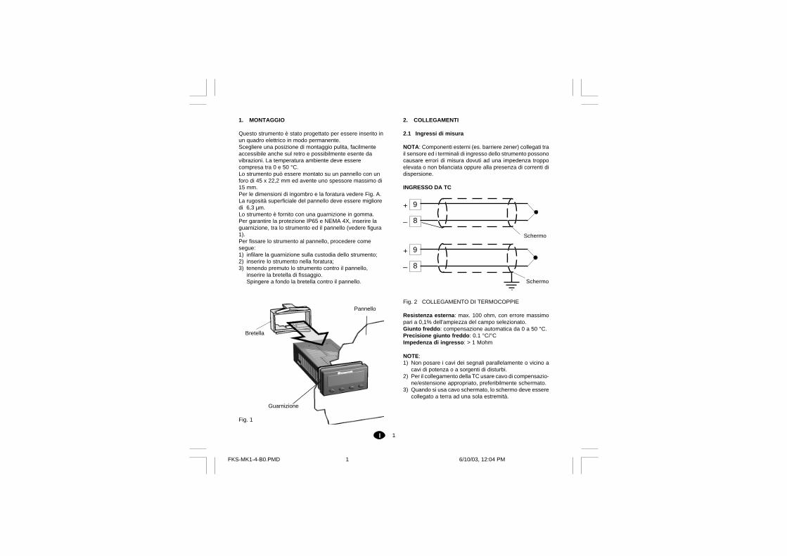
1. MONTAGGIO
Questo strumento è stato progettato per essere inserito inun quadro elettrico in modo permanente.Scegliere una posizione di montaggio pulita, facilmenteaccessibile anche sul retro e possibilmente esente davibrazioni. La temperatura ambiente deve esserecompresa tra 0 e 50 °C.Lo strumento può essere montato su un pannello con unforo di 45 x 22,2 mm ed avente uno spessore massimo di15 mm.Per le dimensioni di ingombro e la foratura vedere Fig. A.La rugosità superficiale del pannello deve essere miglioredi 6,3 µm.Lo strumento è fornito con una guarnizione in gomma.Per garantire la protezione IP65 e NEMA 4X, inserire laguarnizione, tra lo strumento ed il pannello (vedere figura1).Per fissare lo strumento al pannello, procedere comesegue:1) infilare la guarnizione sulla custodia dello strumento;2) inserire lo strumento nella foratura;3) tenendo premuto lo strumento contro il pannello,
inserire la bretella di fissaggio.Spingere a fondo la bretella contro il pannello.
Fig. 1
Guarnizione
Bretella
Pannello
2. COLLEGAMENTI
2.1 Ingressi di misura
NOTA: Componenti esterni (es. barriere zener) collegati trail sensore ed i terminali di ingresso dello strumento possonocausare errori di misura dovuti ad una impedenza troppoelevata o non bilanciata oppure alla presenza di correnti didispersione.
INGRESSO DA TC
Fig. 2 COLLEGAMENTO DI TERMOCOPPIE
Resistenza esterna: max. 100 ohm, con errore massimopari a 0,1% dell'ampiezza del campo selezionato.Giunto freddo: compensazione automatica da 0 a 50 °C.Precisione giunto freddo: 0.1 °C/°CImpedenza di ingresso: > 1 Mohm
NOTE:1) Non posare i cavi dei segnali parallelamente o vicino a
cavi di potenza o a sorgenti di disturbi.2) Per il collegamento della TC usare cavo di compensazio-
ne/estensione appropriato, preferibilmente schermato.3) Quando si usa cavo schermato, lo schermo deve essere
collegato a terra ad una sola estremità.
8
+
_
Schermo
9
8
+
_
Schermo
9
FKS-MK1-4-B0.PMD 6/10/03, 12:04 PM1
2I
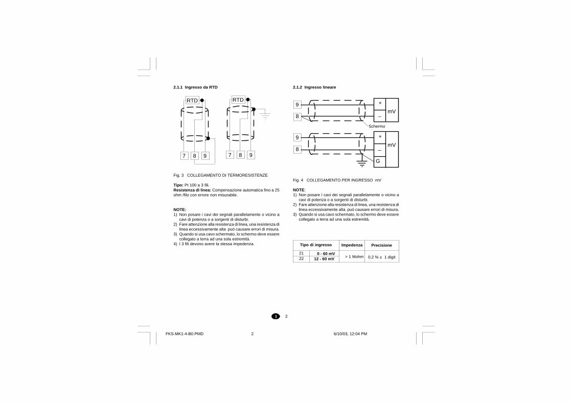
2.1.2 Ingresso lineare
Fig. 4 COLLEGAMENTO PER INGRESSO mV
NOTE:1) Non posare i cavi dei segnali parallelamente o vicino a
cavi di potenza o a sorgenti di disturbi.2) Fare attenzione alla resistenza di linea, una resistenza di
linea eccessivamente alta può causare errori di misura.3) Quando si usa cavo schermato, lo schermo deve essere
collegato a terra ad una sola estremità.
2.1.1 Ingresso da RTD
Fig. 3 COLLEGAMENTO DI TERMORESISTENZE
Tipo: Pt 100 a 3 fili.Resistenza di linea: Compensazione automatica fino a 25ohm /filo con errore non misurabile.
NOTE:1) Non posare i cavi dei segnali parallelamente o vicino a
cavi di potenza o a sorgenti di disturbi.2) Fare attenzione alla resistenza di linea, una resistenza di
linea eccessivamente alta può causare errori di misura.3) Quando si usa cavo schermato, lo schermo deve essere
collegato a terra ad una sola estremità.4) I 3 fili devono avere la stessa impedenza.
7
RTD
98 7
RTD
98
8
Schermo
9
8
9
G
_
+
mV
_
+
mV
0 - 60 mV12 - 60 mV > 1 Mohm
Tipo di ingresso
2122
Impedenza Precisione
0.2 % ± 1 digit
FKS-MK1-4-B0.PMD 6/10/03, 12:04 PM2
3I
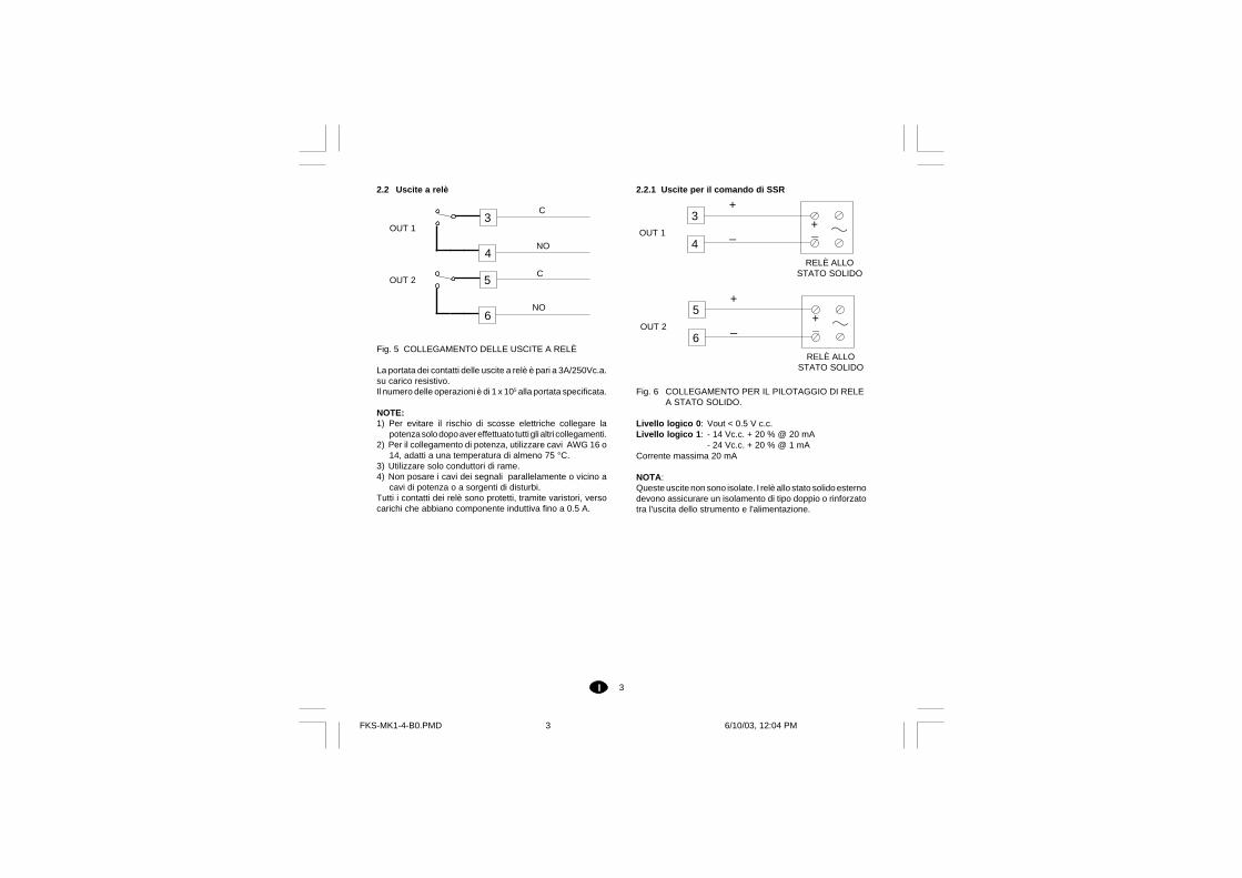
2.2 Uscite a relè
Fig. 5 COLLEGAMENTO DELLE USCITE A RELÈ
La portata dei contatti delle uscite a relè è pari a 3A/250Vc.a.su carico resistivo.Il numero delle operazioni è di 1 x 10⁵ alla portata specificata.
NOTE:1) Per evitare il rischio di scosse elettriche collegare la
potenza solo dopo aver effettuato tutti gli altri collegamenti.2) Per il collegamento di potenza, utilizzare cavi AWG 16 o
14, adatti a una temperatura di almeno 75 °C.3) Utilizzare solo conduttori di rame.4) Non posare i cavi dei segnali parallelamente o vicino a
cavi di potenza o a sorgenti di disturbi.Tutti i contatti dei relè sono protetti, tramite varistori, versocarichi che abbiano componente induttiva fino a 0.5 A.
2.2.1 Uscite per il comando di SSR
Fig. 6 COLLEGAMENTO PER IL PILOTAGGIO DI RELEA STATO SOLIDO.
Livello logico 0: Vout < 0.5 V c.c.Livello logico 1: - 14 Vc.c. + 20 % @ 20 mA
- 24 Vc.c. + 20 % @ 1 mACorrente massima 20 mA
NOTA:Queste uscite non sono isolate. I relè allo stato solido esternodevono assicurare un isolamento di tipo doppio o rinforzatotra l'uscita dello strumento e l'alimentazione.
+
_ _+
3
4OUT 1
RELÈ ALLOSTATO SOLIDO
+
_ _+
5
6OUT 2
RELÈ ALLOSTATO SOLIDO
OUT 1
C3
4NO
5
6NO
COUT 2
FKS-MK1-4-B0.PMD 6/10/03, 12:04 PM3
4I
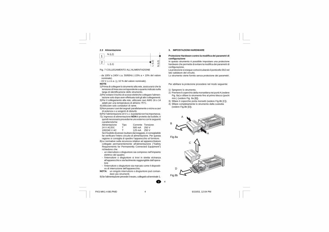
2.3 Alimentazione
Fig. 7 COLLEGAMENTO ALL'ALIMENTAZIONE
- da 100V a 240V c.a. 50/60Hz (-15% a + 10% del valorenominale).
- 24 V c.c./c.a. (+ 10 % del valore nominale).NOTE:1)Prima di collegare lo strumento alla rete, assicurarsi che la
tensione di linea sia corrispondente a quanto indicato sullatarga di identificazione dello strumento.
2)Per evitare il rischio di scosse elettriche collegare l'alimen-tazione solo dopo aver effettuato tutti gli altri collegamenti.
3)Per il collegamento alla rete, utilizzare cavi AWG 16 o 14adatti per una temperatura di almeno 75°C.
4)Utilizzare solo conduttori di rame.5)Non posare i cavi dei segnali parallelamente o vicino a cavi
di potenza o a sorgenti di disturbi.6)Per l'alimentazione 24 V c.c. la polarità non ha importanza.7)L'ingresso di alimentazione NON è protetto da fusibile; è
quindi necessario prevederne uno esterno con le seguenticaratteristiche:Alimentazione Tipo Corrente Tensione24 V AC/DC T 500 mA 250 V100/240 V AC T 125 mA 250 VSe il fusibile dovesse risultare danneggiato, è consigliabilefar verificare l'intero circuito di alimentazione. Per questaragione si consiglia di spedire l'apparecchio al fornitore.
8)Le normative sulla sicurezza relative ad apparecchiaturecollegate permanentemente all'alimentazione ("SafetyRequirements for Permanently Connected Equipment")richiedono che:- un interruttore o disgiuntore sia compreso nell'impianto
elettrico del quadro;- l'interruttore o disgiuntore si trovi in stretta vicinanza
all'apparecchio e sia facilmente raggiungibile dall'opera-tore
- l'interruttore o disgiuntore sia marcato come il dispositi-vo di interruzione dell'apparecchio.
NOTA: un singolo interruttore o disgiuntore può coman-dare più strumenti.
9)Se l'alimentazione prevede il neutro, collegarlo al terminale 1.
3. IMPOSTAZIONI HARDWARE
Protezione Hardware contro la modifica dei parametri diconfigurazioneIn questo strumento è possibile impostare una protezionehardware che permette di evitare la modifica dei parametri diconfigurazione.La protezione si esegue cortocircuitando il ponticello Sh2 nellato saldature del circuito.Lo strumento viene fornito senza protezione dei parametri.
Per abilitare la protezione procedere nel modo seguente:
1) Spegnere lo strumento.2) Premere il coperchio della morsettiera nei punti A (vedere
Fig. 8a) e sfilare lo strumento fino al primo blocco (pochimm.) (vedere Fig. 8a [B]).
3) Sfilare il coperchio porta morsetti (vedere Fig.8b [C]).4) Sfilare completamente lo strumento dalla custodia
(vedere Fig.8b [D]).
2
1N (L2)
L (L1)
N (
L2)
L (L
1)
Fig.8b
Fig.8a
A
A
B
C
D
FKS-MK1-4-B0.PMD 6/10/03, 12:04 PM4
5I
5) Saldare le piazzole del ponticello Sh2 (vedere Fig. 9).6) Inserire lo strumento nella custodia fino al primo blocco.7) Inserire il coperchio porta morsetti.8) Spingere a fondo lo strumento nella custodia.9) Alimentare lo strumento.
4 MODALITÀ DI FUNZIONAMENTO DELLOSTRUMENTO
Le modalità di funzionamento sono due: modoconfigurazione e modo operativo. Sono selezionabili datastiera, come descritto nelle sezioni corrispondenti.All' accensione, lo strumento parte nello stesso "modo" incui era prima dello spegnimento (modo di configurazioneo modo operativo).
5 CONFIGURAZIONE
5.1 Funzioni della tastiera in modalità di configurazio-ne
FUNC memorizza il nuovo valore del parametroselezionato e passa al parametrosuccessivo (ordine crescente).
REV Torna al parametro precedente senzamemorizzare il nuovo valore.
Incrementa il valore del parametro selezionato.Mantenendo la pressione sul pulsante, lavelocità di variazione viene incrementata.
Decrementa il valore del parametroselezionato. Mantenendo la pressione sulpulsante, la velocità di variazione vieneincrementata.
5.2 Come avviare la modalità di configurazione
All'atto dell'accensione possono presentarsi le seguenticondizioni:A) il display mostra un numero: lo strumento è in
modalità operativa e in "modo normale divisualizzazione".
B) il display mostra "E" e un numero: lo strumento harilevato un errore (vedere cap. "Messaggi di errore" inquesto manuale).
C) il display mostra "_ ooo_ ooo_ ooo_ ooo_ ooo" o "- ooo- ooo- ooo- ooo- ooo": lo strumento è inmodalità operativa e in "modo normale divisualizzazione", ma ha rilevato una condizione difuori range.
D) il display mostra "CONFCONFCONFCONFCONF" : lo strumento è in modalità diconfigurazione.
Fig.9
Sh2
FKS-MK1-4-B0.PMD 6/10/03, 12:05 PM5

6I
Per le condizioni A) e C) premere i pulsanti REV + FUNC perpiù di 3 sec. Il display mostra "CONFCONFCONFCONFCONF".A questo punto lo strumento si trova nella condizionedescritta al punto D).
Il passo successivo varia in relazione alla configurazioneprecedentemente eseguita.
5.2.1 Strumento in modalità non protetta
a) Il display mostra:
CONF CONF CONF CONF CONF e alternativamente OFFOFFOFFOFFOFF
b) Premere oper visualizzare ON ON ON ON ON .Confermare premendo il tasto FUNC.Lo strumento si riavvia in modalità Configurazione.
5.2.2 Strumento in modalità protetta
a) Il display mostra:
CONF CONF CONF CONF CONF e alternativamente --------------------
b) Premere o fino a visualizzare lo stesso valoreimpostato al parametro P18 (vedere paragrafo 5.3),oppure il valore di "Passepartout" (vedere cap. 10 "Codicidi sicurezza").Confermare con FUNC.Lo strumento si riavvia in modalità Configurazione.
NOTA:a) Se il valore di P18 è 1, solo il valore di "Passepartout"
consente di passare in modo Configurazione.
5.3 Parametri di configurazione
NOTA:In configurazione, i vari parametri sono semprevisualizzabili, ma sono modificabili solo se laprotezione hardware Sh2 è esclusa (vedere cap. 4"Impostazioni hardware").
Alcuni dei parametri seguenti potrebbero essere omessi inrelazione ai valori assegnati ai parametri precedenti.
Per ogni parametro, lo strumento visualizza alternativamenteil codice di riferimento e il suo valore numerico. Premere oper modificarne il valore numerico.
a) Premere il pulsante FUNC per salvare il nuovo valoree procedere al parametro successivo.
b) Premere il pulsante REV per tornare al parametroprecedente senza memorizzare il nuovo valore delparametro corrente.NOTA:Nessun time out è attivo in modo Configurazione
P1P1P1P1P1 Tipo di ingresso e campo di misura
Campi:* 1 = TC tipo L campo -100 / +900 °C* 2 = TC tipo J campo -100 / +1000 °C* 3 = TC tipo K campo -100 / +1370 °C* 4 = TC tipo T campo -200 / +400 °C
5 = TC tipo N campo -100 / +1400 °C6 = TC tipo S campo -50 / +1760 °C7 = TC tipo R campo -50 / +1760 °C8 = TC tipo B campo 0 / +1820 °C9 = TC tipo W5 campo 0 / +2300 °C
* 10 = RTD Pt100 campo -200 / +850 °C11 = TC tipo L campo -150 / +1650 °F12 = TC tipo J campo -150 / +1830 °F13 = TC tipo K campo -150 / +2500 °F14 = TC tipo T campo -330 / +750 °F15 = TC tipo N campo -150 / +2550 °F16 = TC tipo S campo -60 / +3200 °F
FKS-MK1-4-B0.PMD 6/10/03, 12:05 PM6
7I
17 = TC tipo R campo -60 / +3200 °F18 = TC tipo B campo 32 / +3300 °F19 = TC tipo W5 campo 0 / +4170 °F
* 20 = RTD Pt100 campo -330 / +1560 °F21 = Lineare campo 0 / 60 mV22 = Lineare campo 12 / 60 mV
* Per questi campi è possibile impostare una visualizza-zione della misura con una cifra decimale, lo strumentoperò, non potendo visualizzare una misura minore di -199.9 o maggiore di 999.9, limiterà di conseguenza ilcampo di ingresso.
NOTE:Se viene modificato il tipo di ingresso, lo strumentoforzerà automaticamente:- il parametro "P3" al nuovo valore di inizio scala (0 per
ingressi lineari),- il parametro "P4" al nuovo valore di fondo scala (4000
per ingressi lineari),- il parametro "P16" al nuovo valore di inizio scala,- il parametro "P2" a "nessuna cifra decimale".
P2P2P2P2P2 Posizione del punto decimale
Questo parametro è disponibile solo per gli ingressi da 1 a4, 10, 20 e gli ingressi lineari 21, 22.
----. = Nessuna cifra decimale.---.- = Una cifra decimale.--.-- = Due cifre decimali.-.--- = Tre cifre decimali.
NOTE:a) Per gli ingressi da 1 a 4, 10, 20, è possibile selezionare
"nessuna " o "una cifra decimale"; il campo dell'ingressosarà limitato tra -199,9 e 999,9 e sarà considerato comeun cambiamento del tipo di ingresso.
b) Per gli ingressi lineari (21 e 22) sono disponibili tutte leposizioni.
P3P3P3P3P3 Valore di inizio scala di visualizzazione
Campi:- per gli ingressi lineari il parametro è programmabile da
-1999 a 9999;- per gli ingressi TC/RTD è programmabile dal valore
minimo del campo di misura a "P4" (valore di fondoscala).
NOTE: se il valore di questo parametro viene variato,a) il parametro "rL" verrà allineato al nuovo valore di "P3";b) il parametro "rH" verrà controllato e, se fuori campo,
allineato al valore di "P4";c) se è stato selezionato un ingresso lineare, il valore di
"P16" verrà allineato al valore di "P3".d) i parametri SP/AL1/AL2 (se allarmi di processo) verranno
controllati e, se fuori campo, allineati al nuovo valore di"P3".
P4P4P4P4P4 Valore di fondo scala di visualizzazione
Campi:- per gli ingressi lineari il parametro è programmabile da
-1999 a 9999;- per gli ingressi TC/RTD dal valore di inizio scala (P3) al
valore massimo del campo di misura.NOTE:A) Se il valore di questo parametro è cambiato,
a.1) Il parametro "rL" verrà allineato al nuovo valore di"P3";
a.2) Il parametro "rH" verrà controllato e, se fuoricampo, verrà allineato al nuovo valore di "P4";
a.3) se è stato selezionato un ingresso lineare, il valoredi "P16" verrà allineato al valore di "P3".
a.4) I parametri SP/AL1/AL2 (se allarmi di processo)verranno controllati e, se fuori campo, allineati alnuovo valore di "P3".
B) Lo l'ampiezza del campo di ingresso ("P4" - "P3"), invalore assoluto, deve essere superiore a:- 300°C (550°F) per ingressi TC- 100°C (200°F) per ingressi RTD- 100 digits per ingressi lineari
FKS-MK1-4-B0.PMD 6/10/03, 12:05 PM7
8I
NOTE:a) Se è stato selezionato "rEV", e "P10" (funzione dell'uscita
2) è diverso da "CooL":1 "P53", se inferiore a zero, viene forzato a zero.2 "OLH" se inferiore o uguale a zero viene forzato a 100.3 "OLL" se inferiore a zero viene forzato a zero.4 "IP" è forzato a 50.
b) Se è stato selezionato "dir":1 "P10", se uguale a "CooL", viene forzato a "nonE"2 "P53", se inferiore a zero, viene forzato a zero.3 "OLH" se inferiore o uguale a zero viene forzato a 100.4 "OLL" se inferiore a zero viene forzato a zero.5 "IP" è forzato a 50.
c) Se è stata selezionata l'uscita per l'allarme 1 ("ALr.1"):1 se impostato a "bAnd","dEV" o "CooL", "P10" viene
forzato a "nonE"2 "P56" viene forzato a "nonE"3 La soglia di "AL.1" viene controllata e, se fuori range",
allineata a "P3".
NOTA:Impostando "P6" come allarme, lo strumento diventa unindicatore; tutti i parametri di configurazione e operativi(es. SP, PB, TI ecc.) relativi al controllo PID sarannoesclusi.
P7P7P7P7P7 Allarme 1: modo operativo
Questo parametro è disponibile solo se l'uscita 1 è configuratacome allarme 1 ("P6" = "ALr.1")
Campo: H.A. = Allarme di massima con reset automati-co
L.A. = Allarme di minima con reset automaticoH.L. = Allarme di massima con reset manualeL.L. = Allarme di minima con reset manuale
Per gli ingressi lineari, l'ampiezza del campo diingresso viene controllato al termine della proceduradi configurazione.
Se errato, viene visualizzato "E204". Per terminare laprocedura di configurazione occorre eliminare l'errore.
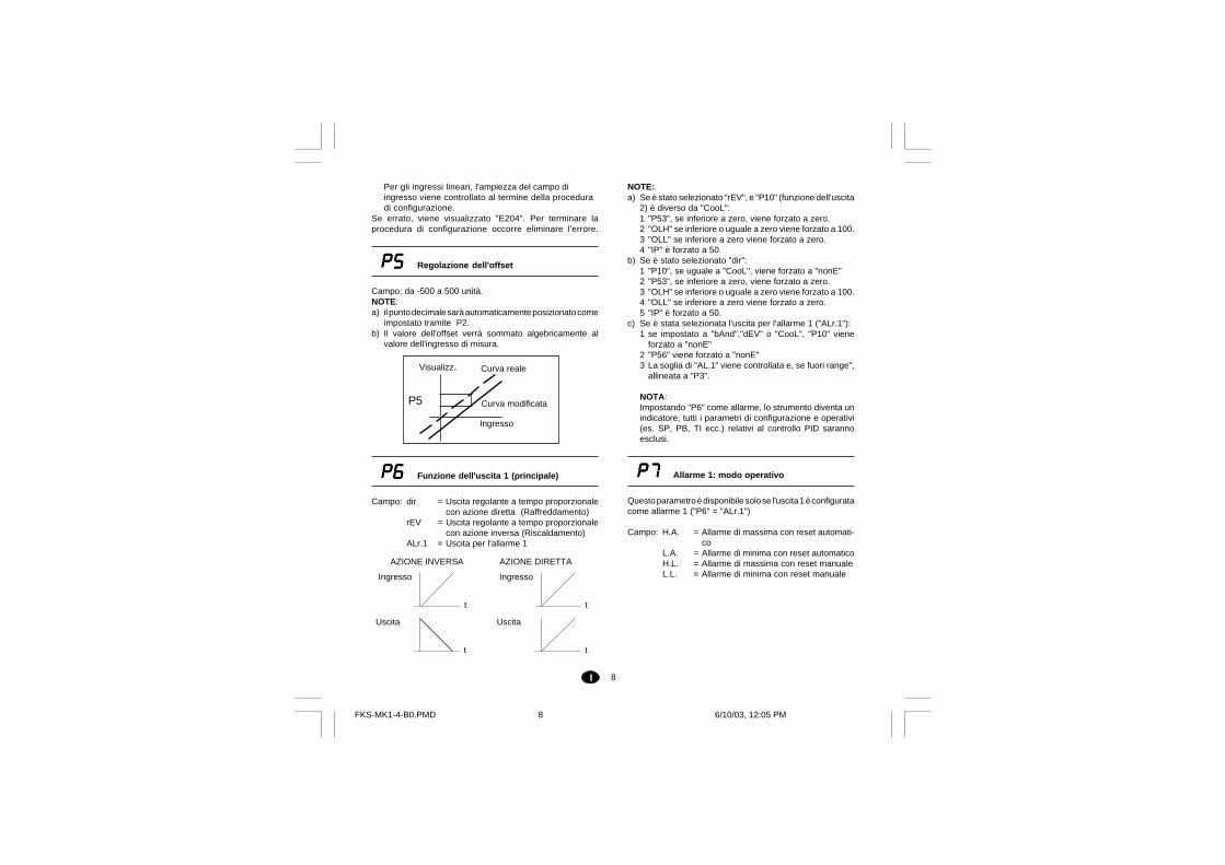
P5P5P5P5P5 Regolazione dell'offset
Campo: da -500 a 500 unità.NOTE:a) il punto decimale sarà automaticamente posizionato come
impostato tramite P2.b) Il valore dell'offset verrà sommato algebricamente al
valore dell'ingresso di misura.
P6P6P6P6P6 Funzione dell'uscita 1 (principale)
Campo: dir = Uscita regolante a tempo proporzionalecon azione diretta (Raffreddamento)
rEV = Uscita regolante a tempo proporzionalecon azione inversa (Riscaldamento)
ALr.1 = Uscita per l'allarme 1
Curva realeVisualizz.
Curva modificata
Ingresso
P5
AZIONE INVERSA AZIONE DIRETTA
t
Ingresso
t
Uscita
t
Ingresso
t
Uscita
FKS-MK1-4-B0.PMD 6/10/03, 12:05 PM8
9I
P8P8P8P8P8 Allarme 1: azione
Questo parametro è disponibile solo se l'uscita 1 èconfigurata come allarme 1 ("P6" = "ALr.1")
Campo: dir = azione diretta (il relè è eccitato o SSr=1in condizioni di allarme)
rEV = azione inversa (il relè è diseccitato oSSr=0 in condizioni di allarme)
P9P9P9P9P9 Allarme 1: mascheratura dell'allarme
Questo parametro è disponibile solo se l'uscita 1 èconfigurata come allarme 1 ("P6" = "ALr.1")
Campo: OFF = mascheratura disabilitataON = mascheratura abilitata
NOTA:- questa funzione consente di "mascherare" una condizio-
ne di allarme all'avvio, finchè la variabile di processoraggiunge la soglia di allarme più o meno l'isteresi.
P10P10P10P10P10 Funzione dell'uscita 2 (secondaria)
Campo: nonE = Uscita non utilizzatanALF = Uscita per segnalare un'anomalia rileva-
ta sulla misuraProc = Uscita allarme 2 - Allarme di processobAnd = Uscita allarme 2 - Allarme di bandadEV = Uscita allarme 2 - Allarme di deviazioneCooL = Uscita usata per il raffreddamento nella
configurazione a due uscite regolanti.
NOTE:a) Se P10 viene impostato come "bAnd" o "dEV", ed il
parametro "P6" è uguale a "AL.1", P6 viene forzato a"rEV"
b) Se l'uscita 2 viene impostata come allarme, la soglia"AL.2" viene controllata e, se fuori campo, verrà
forzata al valore di default.c) Impostando "P10" uguale a "CooL":
1 "P6" viene forzato a "rEV"2 "OLL" viene forzato a -100 e "OLH", se minore o
uguale a zero, viene forzato a 100.3 "IP" viene forzato a zero.
d) Se l'uscita "CooL" viene rimossa, lo strumente eseguel'azione descritta al parametro "P6" (nota a).
P1P1P1P1P111111Tipo di elemento raffreddante o modooperativo allarme 2
Questo parametro è disponibile solo se "P10" è diverso da"nonE".
Quando "P10" è diverso da "CooL":Campo: H.A. = Allarme di massima (allarme all'esterno
della banda) con riarmo automaticoL.A. = Allarme di minima (allarme all'interno
della banda) con riarmo automaticoH.L. = AAllarme di massima (allarme all'ester-
no della banda) con riarmo manualeL.L. = Allarme di minima (allarme all'interno
della banda) con riarmo manualeNOTA: La scelta "di massima o di minima" non ha
effetto se l'uscita è usata come segnalatoredi anomalia.
Quando "P10" è uguale a "CooL":Campo: Air = L'elemento di raffreddamento è aria
OIL = L'elemento di raffreddamento è olioH2O = L'elemento di raffreddamento è acqua.
NOTA:- Variando il tipo di raffreddamento, i parametri "C2" ed
"rC" verranno forzati ai relativi valori di default.
FKS-MK1-4-B0.PMD 6/10/03, 12:05 PM9
10I
P14P14P14P14P14 Funzione SMART
Questo parametro è disponibile se almeno un uscita rego-lante è stata configurata.Campo: dIS = Funzione Smart disabilitata.
Enb = Funzione Smart abilitata (l'attivazione/disattivazione della funzione non è sog-getta alla regola di protezione parame-tri).
Enb.P = Funzione Smart abilitata (l'attivazione/disattivazione della funzione è soggettaalla regola di protezione parametri)
P15P15P15P15P15 Tipo di azione regolante
Questo parametro è disponibile se almeno un uscita rego-lante è stata configurata.Campo: Pid = Il processo è controllato tramite l'azione
PID.Pi = Il processo è controllato tramite l'azione
PI.NOTA:- se il tipo di azione regolante è stato cambiato (parametro
"P15") e la configurazione è stata abilitata mentre eraattiva la seconda parte dell'algoritmo di SMART (Adap-tive), i parametri "Pb" e "ti" verranno aggiornati con i valoricalcolati dal precedente TUNE per il nuovo tipo di azioneregolanteSe questi valori sono sbagliati:- verrà visualizzato per 2 secondi il messaggio di errore
"E.120";- i parametri "Pb" e "ti" non saranno aggiornati;- lo strumento funzionerà con un azione regolante di tipo
PI (il parametro "td" sarà forzato a 0).In tale situazione è consigliabile riavviare la funzioneSMART.
P12P12P12P12P12 Allarme 2: azione
Questo parametro è disponibile solo se la funzione dell'uscita2 è configurata come allarme 2 ("P10" diverso da "nonE" o"CooL")
Campo: dir = azione diretta (il relè è eccitato o SSr=1in condizioni di allarme)
rEV = azione inversa (il relè è diseccitato oSSr=0 in condizioni di allarme)
NOTA:- Se LBA è abilitato sull'uscita 2 ("P56" = "Out2", vedere
manuale "Addendum"), la stessa scelta viene impostata su"P61".
P13P13P13P13P13 Allarme 2: funzione standby
Questo parametro è disponibile solo se la funzione dell'uscita2 è configurata come allarme 2 ("P10" diverso da "nonE","nALF", "CooL").
Campo: OFF = funzione stanby disabilitataON = funzione stanby abilitata
NOTA:- La funzione di standby consente di "mascherare" una
condizione di allarme all'avvio (se l'allarme è programma-to come allarme di processo), o all'avvio / cambio di setpoint (se l'allarme è programmato come banda o devia-zione), finchè la variabile di processo raggiunge la sogliadi allarme più o meno l'isteresi.
FKS-MK1-4-B0.PMD 6/10/03, 12:05 PM10
11I
P16P16P16P16P16 Soglia per abilitazione Soft Start
Questo parametro è disponibile se almeno un uscita rego-lante è stata configurata.
Campo: - All'interno del campo per TC/RTD (vedere "P1")- Allinterno del campo definito da "P3" e "P4" per
ingressi lineari
P17P17P17P17P17 Selezione del time-out
Questo parametro consente di impostare il tempo didurata del timeout utilizzato dallo strumento durante lamodifica dei parametri in modalità operativa.
Campo: tn.10 = time-out 10 sectn.30 = time-out 30 sec
P18P18P18P18P18 Codice di sicurezza
Campo:0 = Nessuna protezione. Il dispositivo è semprein condizione NON PROTETTA e tutti i para-metri operativi possono essere sempre mo-dificati
1 = Protezione totale. Il dispositivo è sempre incondizione PROTETTA e nessun parametrooperativo (fatta eccezione per i parametri"SP","n.rST") può essere modificato
2/4999 = Codice per abilitare/disabilitare la protezionedei parametri operativi (Vedere "nnn")(I parametri "SP" e "n.rST" NON sono sog-getti a protezione).
5000/9999 = Codice per abilitare/disabilitare la protezionedei parametri operativi (Vedere "nnn") .I pa-rametri "SP","n.rST", "AL.1", "AL.2", NONsono soggetti a protezione.
I PARAMETRI PROTETTI NON SARANNO VISUALIZZATI
NOTE:a) Per l'abilitazione/disabilitazione dell'algoritmo SMART
vedere anche "P14"b) Quando viene selezionato un codice numerico,lo stesso
non verrà più visualizzato (il display mostrerà "2").Se sidimentica il codice sarà necessario impostarne uno nuo-vo
La configurazione base dello strumento è terminata, e ildisplay mostra:
C.EndC.EndC.EndC.EndC.EndPremere FUNC per tornare all'inizio della configurazione.
COnFCOnFCOnFCOnFCOnFPer passare al modo operativo premere per 3 secondi REV+ FUNC.
NOTA:Nel manuale "Addendum " è riportata la programmazione deiparametri da "P51" a "P66".
FKS-MK1-4-B0.PMD 6/10/03, 12:05 PM11
12I
Incrementa il valore del parametro selezionato.Mantenendo la pressione sul pulsante, lavelocità di variazione viene incrementata.
Decrementa il valore del parametroselezionato. Mantenendo la pressione sulpulsante, la velocità di variazione vieneincrementata.
+ Quando lo strumento è in "modo normale divisualizzazione", consentono di ripristinare iparametri di default (vedere cap. 10 "Parametridi default ")
REV + FUNC Quando lo strumento è in "modo normale di
visualizzazione", se premuti per più di 3 sec.,consentono di commutare dalla procedura diconfigurazione a quella operativa o viceversa.
NOTA:Nella modalità operativa, per la modifica dei parametripuò essere selezionato un time out di 10 o 30 secondi(vedere parametro "P17" in "Configurazione").Se durante la modifica di un parametro, non vienepremuto alcun pulsante per un periodo superiore altime out (10 o 30 secondi), lo strumento tornaautomaticamente al "modo normale di visualizzazione"perdendo l'eventuale modifica dell'ultimo parametroselezionato.
6.2 Visualizzazioni alternative
Quando lo strumento è nel modo normale di visualizzazione,è possibile cambiare l'informazione visualizzata sul displaynel modo seguente:a) premendo il tasto FUNC per più di 3 sec., il display
mostrerà lo stato dell'allarme LBA (se configurato) nelmodo seguente:"L.b.OF" = nessun allarme"L.b.AL" = condizione di allarme
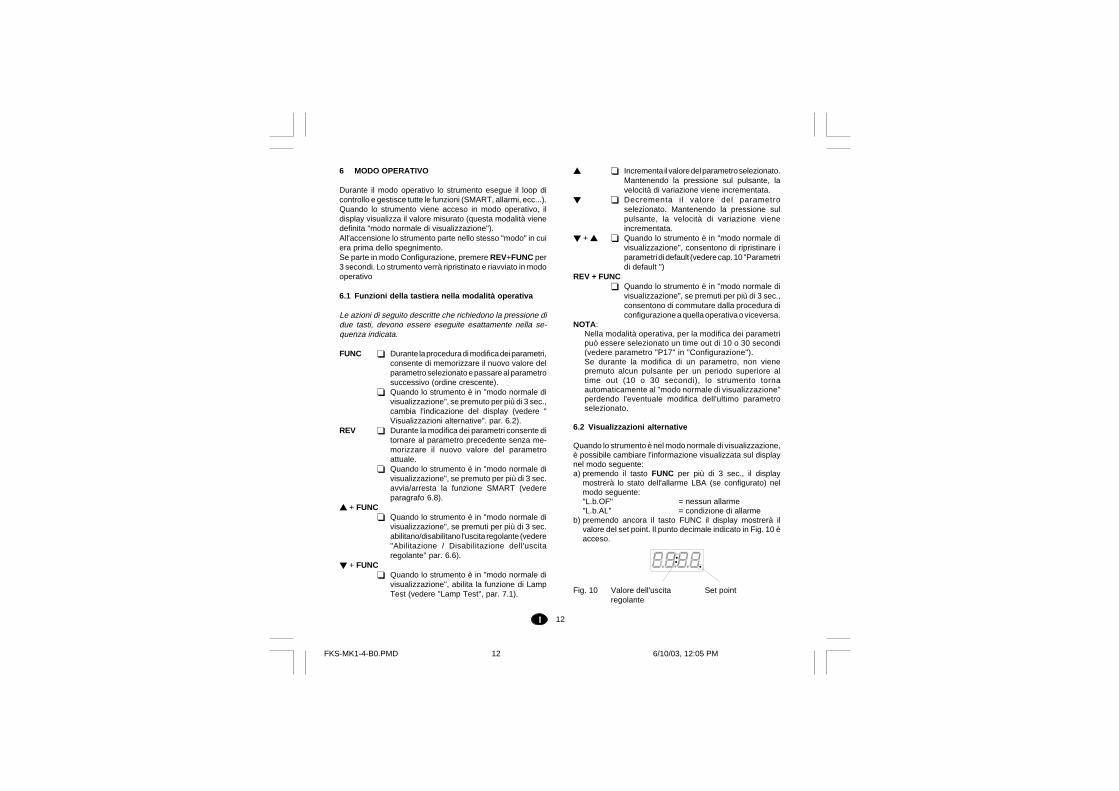
b) premendo ancora il tasto FUNC il display mostrerà ilvalore del set point. Il punto decimale indicato in Fig. 10 èacceso.
Fig. 10 Valore dell'uscita Set pointregolante
6 MODO OPERATIVO
Durante il modo operativo lo strumento esegue il loop dicontrollo e gestisce tutte le funzioni (SMART, allarmi, ecc...).Quando lo strumento viene acceso in modo operativo, ildisplay visualizza il valore misurato (questa modalità vienedefinita "modo normale di visualizzazione").All'accensione lo strumento parte nello stesso "modo" in cuiera prima dello spegnimento.Se parte in modo Configurazione, premere REV+FUNC per3 secondi. Lo strumento verrà ripristinato e riavviato in modooperativo
6.1 Funzioni della tastiera nella modalità operativa
Le azioni di seguito descritte che richiedono la pressione didue tasti, devono essere eseguite esattamente nella se-quenza indicata.
FUNC Durante la procedura di modifica dei parametri,consente di memorizzare il nuovo valore delparametro selezionato e passare al parametrosuccessivo (ordine crescente).
Quando lo strumento è in "modo normale divisualizzazione", se premuto per più di 3 sec.,cambia l'indicazione del display (vedere "Visualizzazioni alternative". par. 6.2).
REV Durante la modifica dei parametri consente ditornare al parametro precedente senza me-morizzare il nuovo valore del parametroattuale.
Quando lo strumento è in "modo normale divisualizzazione", se premuto per più di 3 sec.avvia/arresta la funzione SMART (vedereparagrafo 6.8).
+ FUNC Quando lo strumento è in "modo normale di
visualizzazione", se premuti per più di 3 sec.abilitano/disabilitano l'uscita regolante (vedere"Abilitazione / Disabilitazione dell'uscitaregolante" par. 6.6).
+ FUNC Quando lo strumento è in "modo normale di
visualizzazione", abilita la funzione di LampTest (vedere "Lamp Test", par. 7.1).
FKS-MK1-4-B0.PMD 6/10/03, 12:05 PM12
13I
c) premendo ancora il tasto FUNC il display mostrerà ilvalore dell'uscita regolante; i due punti indicati in Fig.10 saranno accesi.Il valore dell'uscita regolante PRINCIPALE èvisualizzato nelle due cifre più significative, mentre ilvalore dell'uscita regolante SECONDARIA èvisualizzato nelle due cifre meno significative.NOTE:1) Il simbolo grafico " " mostra che il valore della
rispettiva uscita è uguale a 100%.2) Se l'uscita regolante è disabilitata, il display
mostrerà OFF.NOTE:a) Le visualizzazioni alternative del display sono soggette al
time out. Per rimuovere il time out premere o.b) Quando viene rilevato l'allarme LBA, l'indicazione di cui al
punto a) viene forzata automaticamente. In questo casoil tipo di visualizzazione non è soggetto al timeout.
6.3 Indicatori luminosi
Sul lato sinistro del display sono presenti tre indicatoriluminosi.ST Lampeggia quando la prima fase dell'algoritmo
SMART è in funzione (TUNE).Acceso quando la seconda fase dell'algoritmoSMART è in funzione (ADAPTIVE)
1 Acceso quando l'uscita 1, usata come uscitaregolante, è in condizione ON, o quando l'allarme 1è in stato di allarme.
2 Acceso quando l'uscita 2, usata come uscitaregolante, è in condizione ON, o quando l'allarme 2è in stato di allarme.
6.4 Come controllare o modificare i parametri operativi
Quando lo strumento è in modo normale di visualizzazioneè possibile verificare o modificare i parametri operativi nelmodo seguente:1) Premere il tasto FUNC per far avanzare i parametri
(REV per tornare indietro); il display mostrerà il codicemnemonico del parametro e, alternativamente, il suovalore (o il suo stato).
2) Per variare il valore o lo stato, premere i tasti o (nelcaso di un valore numerico premere per incrementare,per decrementare).
3) Premere il tasto FUNC per memorizzare il nuovo valore(o il nuovo stato) e passare al parametro successivo.Premere REV per visualizzare il parametro precedentesenza memorizzare il nuovo valore.
4) È possibile uscire dalla modifica/verifica dei parametrioperativi:- automaticamente, dopo il time out (vedere la nota c)- manualmente, premendo ripetutamente il tasto FUNC.
NOTE:a) In relazione alla configurazione dello strumento, qualche
parametro potrebbe non essere visualizzato.b) Ad eccezione del set point e degli allarmi ("SP","n.rST",
"AL.1", "AL.2", vedere "P18" nel paragrafo 5.2), i rimanentiparametri possono essere modificati solo quando laprotezione è esclusa.I parametri protetti non sono visualizzati.
c) La verifica e la modifica dei parametri sono soggetti a timeout (vedere "P17" nel paragrafo 5.2), trascorso questotempo, lo strumento tornerà nel "modo normale divisualizzazione" e le eventuali modifiche dell'ultimoparametro visualizzato verranno perse.
6.5 Parametri operativi
SPSPSPSPSP Set Point
Questo parametro è disponibile se almeno un uscita rego-lante è stata configurata.Campo: da rL a rH
n.rStn.rStn.rStn.rStn.rSt Reset manuale degli allarmi
Questo parametro è disponibile se almeno un allarme dispo-ne della funzione di reset manuale.Campo: On = funzione attiva
OFF = nessuna azioneNOTA:- Per riarmare gli allarmi, selezionare ON quindi premere
FUNC.
FKS-MK1-4-B0.PMD 6/10/03, 12:05 PM13
14I
AL.2AL.2AL.2AL.2AL.2 Soglia allarme 2
Questo parametro è disponibile solo se l'uscita 2 è configuratacome allarme (“P10" = "Proc", "bAnd" o ”dEV", vedereparagrafo 5.2).Campo: - all'interno del campo impostato tramite "P3" e
"P4" se allarme di processo (P10 ="Proc")- da 0 a 1000 se allarme di banda ( P10 = "bAnd")- da -1000 a 1000 se allarme di deviazione
(P10 = "dEV")
HSA.2HSA.2HSA.2HSA.2HSA.2 Isteresi allarme 2
Questo parametro è disponibile solo se l'uscita 2 è configuratacome allarme (“P10" = "Proc", "bAnd" o ”dEV", vedereparagrafo 5.2).Campo: da 1 a 200 unitàNOTA: Se "P10" è programmato come allarme di banda,l'isteresi viene limitata dal valore di soglia impostato al puntoprecedente.
PBPBPBPBPB Banda proporzionale
Questo parametro è disponibile quando è configurata alme-no un'uscita regolante.Campo: da 1.0% a 100.0% del campo di ingresso ("P3" /"P4"). Impostare 0.0% per un controllo di tipo On/OFF.NOTE:a) La risoluzione di Pb sarà uguale a: 0.1% fino al 10.0% e
1% dal 10.0% al 100.0%.b) Quando lo strumento utilizza l'algoritmo SMART, il valore
di "Pb" sarà limitato come selezionato dai parametri"P62"” e “P63” (vedere "Addendum").
nnnnnnnnnnnnnnn Chiave software
Questo parametro è disponibile se "P18" è uguale o maggio-re di 2 (vedere par. 5.2).Campo: da 2 a 9999. Inserire il codice assegnato e preme-
re il tasto FUNC.NOTA:- Inizialmente sul dispaly apparirà lo stato della protezione
dei parametri.On Protezione attivataOFF Protezione disattivataImpostare il valore assegnato a "P18" per disattivare laprotezione, impostare un valore diverso per attivarla.
AL.1AL.1AL.1AL.1AL.1 Soglia allarme 1
Questo parametro è disponibile solo se l'uscita 1 è configuratacome allarme (“P6" = "ALr.1”, vedere paragrafo 5.2).
Campo: all'interno del campo impostato tramite "P3" e"P4".
HSA.1HSA.1HSA.1HSA.1HSA.1 Isteresi allarme 1
Questo parametro è disponibile solo se l'uscita 1 è configuratacome allarme (“P6" = "ALr.1”, vedere paragrafo 5.2).Campo: da 1 a 200 unità
FKS-MK1-4-B0.PMD 6/10/03, 12:05 PM14
15I
HysHysHysHysHys Isteresi (per controllo di tipo ON/OFF)
Questo parametro è disponibile quando è configurata alme-no un'uscita regolante e Pb =0 (controllo On/OFF)Campo: da 0.1% a 10.0% del campo di ingresso ("P3" /"P4").
tititititi Tempo integrale
Questo parametro è disponibile quando è configurata alme-no un'uscita regolante e Pb è diverso da 0.Campo: da 00.01a 20.00 mm.ss
Oltre questo valore il display si oscura (ad eccezionedel punto decimale) e l'azione integrale risultaesclusa.
NOTA: Quando lo strumento utilizza l'algoritmo SMART, ilvalore di “ti” sarà limitato come selezionato dai parametri“P64” e “P65” (vedere "Addendum").
tdtdtdtdtd Tempo dell'azione derivativa
Questo parametro è disponibile quando è configurata alme-no un'uscita regolante, “P15” è uguale a “Pid” e "Pb" èdiverso da 0.Campo: da 00.00 a 10.00 mm.ssNOTA: Quando lo strumento utilizza l'algoritmo SMART, “td”sarà proporzionale al valore di “ti”, in accordo con quantocalcolato dal TUNE.
IPIPIPIPIP Precarica dell'azione integrale
Questo parametro è disponibile quando è configurata alme-no una uscita regolante e "Pb" è diverso da 0.Campi:- da 0 a 100.0 % dell'uscita quando lo strumento è
configurato con una uscita regolante.- da -100 a 100 % dell'uscita quando lo strumento è
configurato con due uscite regolanti.
CCCCC Tempo di ciclo dell'uscita principale
Questo parametro è disponibile se l'uscita 1 è configuratacome uscita regolante.Campo: da 1 a 200 sec.
C2C2C2C2C2 Tempo di ciclo dell'uscita secondaria
Questo parametro è disponibile se l'uscita 2 è configuratacome uscita regolante.Campo: da 1 a 200 sec.
rCrCrCrCrC Guadagno relativo dell'uscita second.
Questo parametro è disponibile se l'uscita 2 è configuratacome uscita regolante.Campo: da 0.20 a 1.00NOTA:- Quando lo strumento utilizza l'algoritmo SMART e "P66"=
ON, il valore di rC viene limitato in relazione al tipo dielemento raffreddante utilizzato ("P11", vedere par. 5.2):0.85 - 1.00 se aria0.80 - 0,90 se olio0.30 - 0.60 se acqua
FKS-MK1-4-B0.PMD 6/10/03, 12:05 PM15
16I
OLHOLHOLHOLHOLH Limite superiore dell'uscita regolante
Questo parametro è disponibile quando è configurata alme-no un'uscita regolante.Campo: da OLL a 100.
tOLtOLtOLtOLtOL Durata della funzione soft start
Questo parametro è disponibile se almeno un'uscita èconfigurata come uscita regolante.Campo: da 1 a 540 minuti.Oltre questo valore, il display indica "InF" e l'azione limitatricesarà sempre attiva indipendentemente dalla soglia imposta-ta con "P16".NOTA:tOL può essere sempre modificato e:- se la nuova impostazione è compresa tra 1 e 540, avrà
effetto alla successiva accensione dello strumento oppurequando lo strumento ritorna a regolare dopo unadisabilitazione dell'azione regolante;
- se la nuova impostazione è "InF" avrà effetto immediato.
OLAPOLAPOLAPOLAPOLAPSovrapposizione/banda morta tral'uscita principale e l'uscita secondaria
Questo parametro è disponibile se l'uscita 2 è configuratacome uscita regolante.Campo: da -20 a 50NOTA: Un valore negativo indica una banda morta mentreun valore positivo indica una sovrapposizione.
rLrLrLrLrL Limite inferiore del set point
Questo parametro è disponibile quando è configurata alme-no un'uscita regolante.Campo: da “P3” a rH.NOTA: se "rL" viene modificato e il suo nuovo valore èmaggiore del valore di set point ("SP"), il valore di SP verràriallineato a "rL".
rHrHrHrHrH Limite superiore del set point
Questo parametro è disponibile quando è configurata alme-no un'uscita regolante.Campo: da “rL” a "P4"..NOTA: se "rH" viene modificato e il suo nuovo valore èminore del valore di SP, il valore di SP verrà riallineato a "rH".
OLLOLLOLLOLLOLL Limite inferiore dell'uscita regolante
Questo parametro è disponibile quando è configurata alme-no un'uscita regolante.Campo: da 0 a OLH se lo strumento è configurato con
un'uscita regolante.da -100 a OLH se lo strumento è configurato condue uscite regolanti.
FKS-MK1-4-B0.PMD 6/10/03, 12:05 PM16
17I
6.6 Abilitazione/disabilitazione dell'uscita regolante
Quando l'uscita regolante è disabilitata, tutte le uscite regolantie gli allarmi andranno in stato di OFF e lo strumento opereràcome un semplice indicatore, visualizzando il valore misurato.Per abilitare/disabilitare l'uscita regolante premere per più di3 sec. i pulsanti + FUNC quando lo strumento è nel "modonormale di visualizzazione".Il comando di abilitazione/disabilitazione non è soggetto allaregola di protezione dei parametri operativi.Quando l'uscita regolante è disabilitata sono disponibili tuttele funzioni del display (se è richiesta la potenza di uscita, ildisplay visualizzerà "OFF").
Gli allarmi (se configurati) non saranno operativi.
Se lo strumento si dovesse spegnere, alla riaccensionel'uscita regolante rimarrà disabilitata.Quando l'uscita regolante viene nuovamente abilitata, tuttele funzioni verranno attivate come per una accensione dellostrumento.
6.7 Modifica diretta del set point
Quando lo strumento è nel "modo normale di visualizzazione"ed è stata configurata almeno un'uscita regolante, è possibileaccedere direttamente alla modifica del set point.Premendo il tasto o per più di 2 s, verrà visualizzato ilset point (il punto decimale a destra della cifra menosignificativa sarà acceso) ed il suo valore inizierà a cambiare.Il nuovo valore del set point sarà operativo 2 sec. dopol'ultima pressione dei tasti. Il display tornerà a visualizzareil valore misurato.
6.8 Funzione SMART
Consente di ottimizzare automaticamente l'uscita regolante.La funzione prevede due algoritmi, definiti TUNE e ADAPTIVE.Il primo calcola i parametri all'atto dell'avvio del processo.Durante questa fase, l'uscita regolante varia dal massimovalore della scala a 0, e viceversa. Lo strumento può essereposto in qualsiasi momento in modalità TUNE. I parametricorretti vengono calcolati automaticamente dopo che sisono verificati due picchi successivi.La funzione ADAPTIVE è utilizzata per riottimizzare i para-metri PID se cambiano le caratteristiche del processo.L'algoritmo ADAPTIVE parte automaticamente dopo il"TUNE". Se non è necessaria, disattivare la funzione SMARTalla fine del TUNE.
Per abilitare/disabilitare la funzione SMART, premere il tastoREV per più di 3 sec., quando lo strumento si trova nel "modonormale di visualizzazione". L' azione può essere protetta omeno (vedere "P14")Il LED ST lampeggerà durante la prima fase dell'algoritmoSMART (TUNE), mentre sarà acceso a luce fissa durante laseconda fase (ADAPTIVE).
Quando la funzione SMART è abilitata, è possibile visualiz-zare ma non modificare i parametri di controllo.
NOTA: la funzione SMART non può essere attivata quando:- è impostato il controllo ON/OFF (Pb=0);- l'uscita regolante è disabilitata;- la funzione SMART non è stata configurata.
6.9 Funzione SOFT START
All'atto dell'avvio del processo, se il valore misurato è inferiorealla soglia impostata al parametro "P16" (vedere par. 5.3), lostrumento limiterà l'uscita regolante secondo quanto definitoa "OLL" / "OLH", per il tempo definito a "tOL".Se "tOL" è uguale a infinito, il valore di "P16" non viene presoin considerazione e l'uscita sarà sempre limitata a "OLL" /"OLH".
FKS-MK1-4-B0.PMD 6/10/03, 12:05 PM17
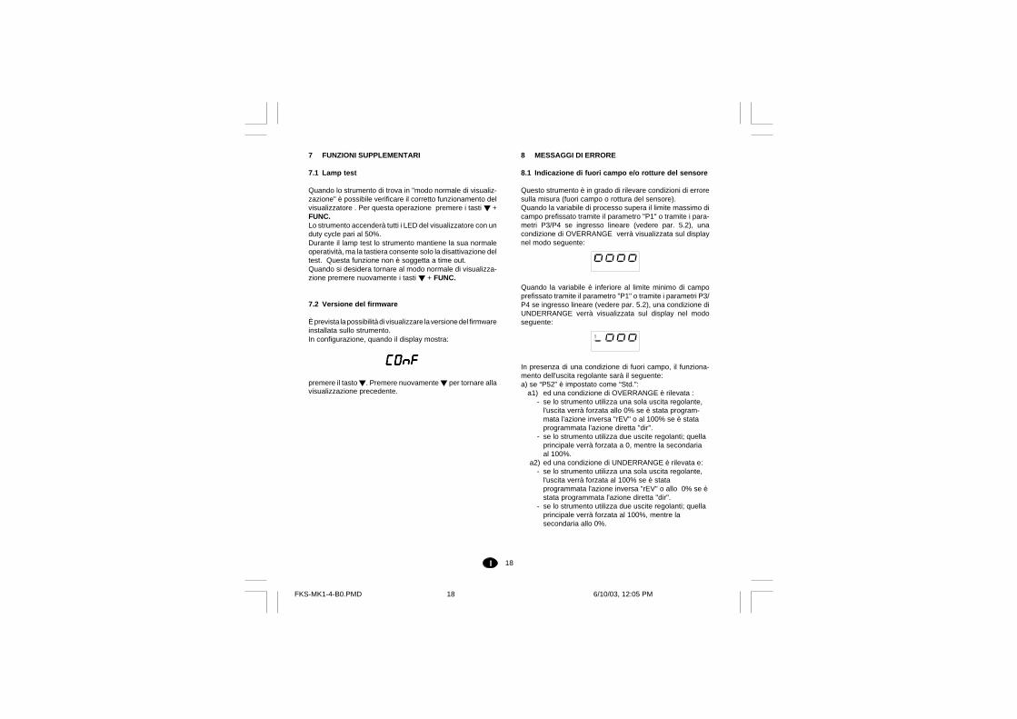
18I
8 MESSAGGI DI ERRORE
8.1 Indicazione di fuori campo e/o rotture del sensore
Questo strumento è in grado di rilevare condizioni di erroresulla misura (fuori campo o rottura del sensore).Quando la variabile di processo supera il limite massimo dicampo prefissato tramite il parametro "P1" o tramite i para-metri P3/P4 se ingresso lineare (vedere par. 5.2), unacondizione di OVERRANGE verrà visualizzata sul displaynel modo seguente:
Quando la variabile è inferiore al limite minimo di campoprefissato tramite il parametro "P1" o tramite i parametri P3/P4 se ingresso lineare (vedere par. 5.2), una condizione diUNDERRANGE verrà visualizzata sul display nel modoseguente:
In presenza di una condizione di fuori campo, il funziona-mento dell'uscita regolante sarà il seguente:a) se “P52” è impostato come “Std.”:
a1) ed una condizione di OVERRANGE è rilevata :- se lo strumento utilizza una sola uscita regolante,
l'uscita verrà forzata allo 0% se è stata program-mata l'azione inversa "rEV" o al 100% se è stataprogrammata l'azione diretta "dir".
- se lo strumento utilizza due uscite regolanti; quellaprincipale verrà forzata a 0, mentre la secondariaal 100%.
a2) ed una condizione di UNDERRANGE è rilevata e:- se lo strumento utilizza una sola uscita regolante,
l'uscita verrà forzata al 100% se è stataprogrammata l'azione inversa "rEV" o allo 0% se èstata programmata l'azione diretta "dir".
- se lo strumento utilizza due uscite regolanti; quellaprincipale verrà forzata al 100%, mentre lasecondaria allo 0%.
7 FUNZIONI SUPPLEMENTARI
7.1 Lamp test
Quando lo strumento di trova in "modo normale di visualiz-zazione" è possibile verificare il corretto funzionamento delvisualizzatore . Per questa operazione premere i tasti +FUNC.Lo strumento accenderà tutti i LED del visualizzatore con unduty cycle pari al 50%.Durante il lamp test lo strumento mantiene la sua normaleoperatività, ma la tastiera consente solo la disattivazione deltest. Questa funzione non è soggetta a time out.Quando si desidera tornare al modo normale di visualizza-zione premere nuovamente i tasti + FUNC.
7.2 Versione del firmware
È prevista la possibilità di visualizzare la versione del firmwareinstallata sullo strumento.In configurazione, quando il display mostra:
CONFCONFCONFCONFCONF
premere il tasto. Premere nuovamente per tornare allavisualizzazione precedente.
FKS-MK1-4-B0.PMD 6/10/03, 12:05 PM18
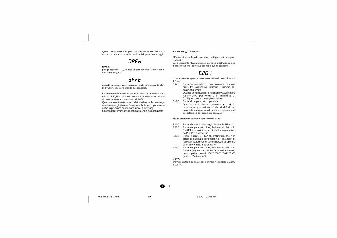
19I
Questo strumento è in grado di rilevare la condizione dirottura del sensore, visualizzando sul display il messaggio:
OPEnOPEnOPEnOPEnOPEnNOTA:per gli ingressi RTD, tramite un test speciale, viene segna-lato il messaggio:
ShrtShrtShrtShrtShrtquando la resistenza di ingresso risulta inferiore a 12 ohm(rilevazione del cortocircuito del sensore).
Lo strumento è inoltre in grado di rilevare un errore sullamisura del giunto di riferimento RJ (E.502) ed un erroredurante la misura di auto-zero (E.500).Quando viene rilevata una condizione diversa da overrangeo underrange, gli allarmi e l'uscita regolante si comporterannocome in presenza di una condizione di overrange.I messaggi di errore sono segnalati su AL2 (se configurato).
8.2 Messaggi di errore
All'accensione nel modo operativo, tutti i parametri vengonoverificati.Se lo strumento rileva un errore, ne viene mostrato il codicedi identificazione, come ad esempio quello seguente:
E.201E.201E.201E.201E.201Lo strumento esegue un reset automatico dopo un time outdi 3 sec.E.2xx Errore di un parametro di configurazione. Le ultime
due cifre significative indicano il numero delparametro errato.Quando uno di questi errori viene rilevato, premereREV+FUNC per entrare in modalità diConfigurazione e correggere il valore.
E.400 Errore di un parametro operativo.Quando viene rilevato, premere + insuccessione per caricare i valori di default deiparametri operativi, quindi ripetere la procedura diimpostazione dei parametri operativi.
Alcuni errori che possono essere visualizzati:
E.100 Errore durante il salvataggio dei dati in EEpromE.120 Errore nei parametri di regolazione calcolati dallo
SMART quando il tipo di controllo è stato cambiatoda PI a PID o viceversa.
E.130 Errore durante lo SMART. L'algoritmo non è ingrado di calcolare correttamente i parametri diregolazione. Lo strumento verrà forzato ad operarecon l'azione regolante di tipo PI.
E.140 Errore nei parametri di regolazione calcolati dalloSMART (algoritmo ADAPTIVE). I valori sono fuoridal campo impostato in "P62", "P63", "P64", "P65"(vedere "Addendum")
NOTA:premere un tasto qualsiasi per eliminare l'indicazione E.130o E.140.
FKS-MK1-4-B0.PMD 6/10/03, 12:05 PM19
20I
E.500 Errore durante la misura di auto-zeroE.502 Errore durante la misura di CJ
NOTA: questo errore può essere generato da unatemperatura ambiente maggiore di 70 °C o minoredi -20°C
E.510 Errore durante la calibrazione.
Se viene rilevato uno di questi errori, contattare il fornitore.
Lo strumento controlla anche la presenza di eventuali errorifatali. Se rilevati, visualizza un apposito codice e, dopo 2sec., ripristina il sistema e si riavvia.
0. errore sullo "stack pointer" della CPU4. errore sui segnali di controllo della EEprom5. sequenza programma errata durante l'accesso a
EEprom6. time out dal "watchdog" (compare anche passando
dal modo configurazione a quello operativo e vice-versa).
9 CARATTERISTICHE TECNICHE
Custodia: Policarbonato trasparente di colore marrone.Grado di autoestinguenza: V2 secondo UL 94Protezione frontale: Il prodotto è stato progettato e verifica-to per garantire una protezione IP 65 e NEMA 4X per uso inluogo coperto.(le verifiche sono state eseguite in accordo agli standard CEI70-1 e NEMA 250-1991)Peso: 90 g.Autoconsumo: 2.5 Watt massimo.Isolamento: secondo EN 61010-1Tempo di aggiornamento del display: 500 ms.Intervallo di campionamento:- 250 ms per ingressi lineari- 500 ms per ingressi da TC o RTDPrecisione: + 0,2% del valore di fondo scala.+ 1 digit @ 25 °C e tensione di alimentazione nominale.Reiezione di modo comune: 120 dB @ 50/60 Hz.Reiezione di modo normale: 60 dB @ 50/60 Hz.Compatibilità elettromagnetica e normative di sicurez-za: Questo strumento è conforme alle direttive EEC 89/336(standard armonizzato di riferimento EN 61326) Requisiti di emissione:Classe A per alimentazione 24 VAC/DCClasse B per alimentazione 100/240 VAC)Questo strumento è conforme alle direttive 73/23 EEC e 93/68 EEC (standard armonizzato di riferimento EN 61010-1)Categoria di installazione: IIGrado di inquinamento: 2Deriva termica: (CJ esclusa)< 200 ppm/°C dello span per campi lineari e TC tipo K, T, N< 250 ppm/°C dello span per campi TC tipo L, J, S, R, B< 350 ppm/°C dello span per campo TC tipo W5< 500 ppm/°C dello span per campi RtdTemperatura di funzionamento: da 0 a 50 °C.Temperatura di immagazzinamento: -20 a +70 °CUmidità: da 20 % a 85% RH, senza condensa.Tempo di aggiornamento dell'uscita regolante:- 250 ms se è stato selezionato un ingresso lineare- 500 ms se è stato selezionato un ingresso da TC o RTD.
FKS-MK1-4-B0.PMD 6/10/03, 12:05 PM20
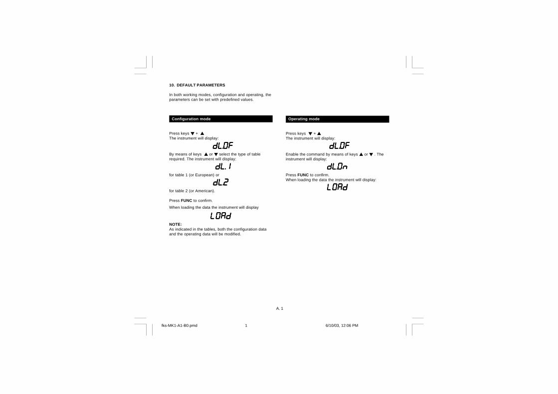
A. 1
10. DEFAULT PARAMETERS
In both working modes, configuration and operating, theparameters can be set with predefined values.
Configuration mode
Press keys +The instrument will display:
dL.OFdL.OFdL.OFdL.OFdL.OFBy means of keys or select the type of tablerequired. The instrument will display:
dL.1dL.1dL.1dL.1dL.1for table 1 (or European) or
dL.2dL.2dL.2dL.2dL.2for table 2 (or American).
Press FUNC to confirm.
When loading the data the instrument will display
LOAdLOAdLOAdLOAdLOAdNOTE:As indicated in the tables, both the configuration dataand the operating data will be modified.
Operating mode
Press keys + The instrument will display:
dL.OFdL.OFdL.OFdL.OFdL.OFEnable the command by means of keys or . Theinstrument will display:
dL.ONdL.ONdL.ONdL.ONdL.ONPress FUNC to confirm.When loading the data the instrument will display:
LOAdLOAdLOAdLOAdLOAd
fks-MK1-A1-B0.pmd 6/10/03, 12:06 PM1
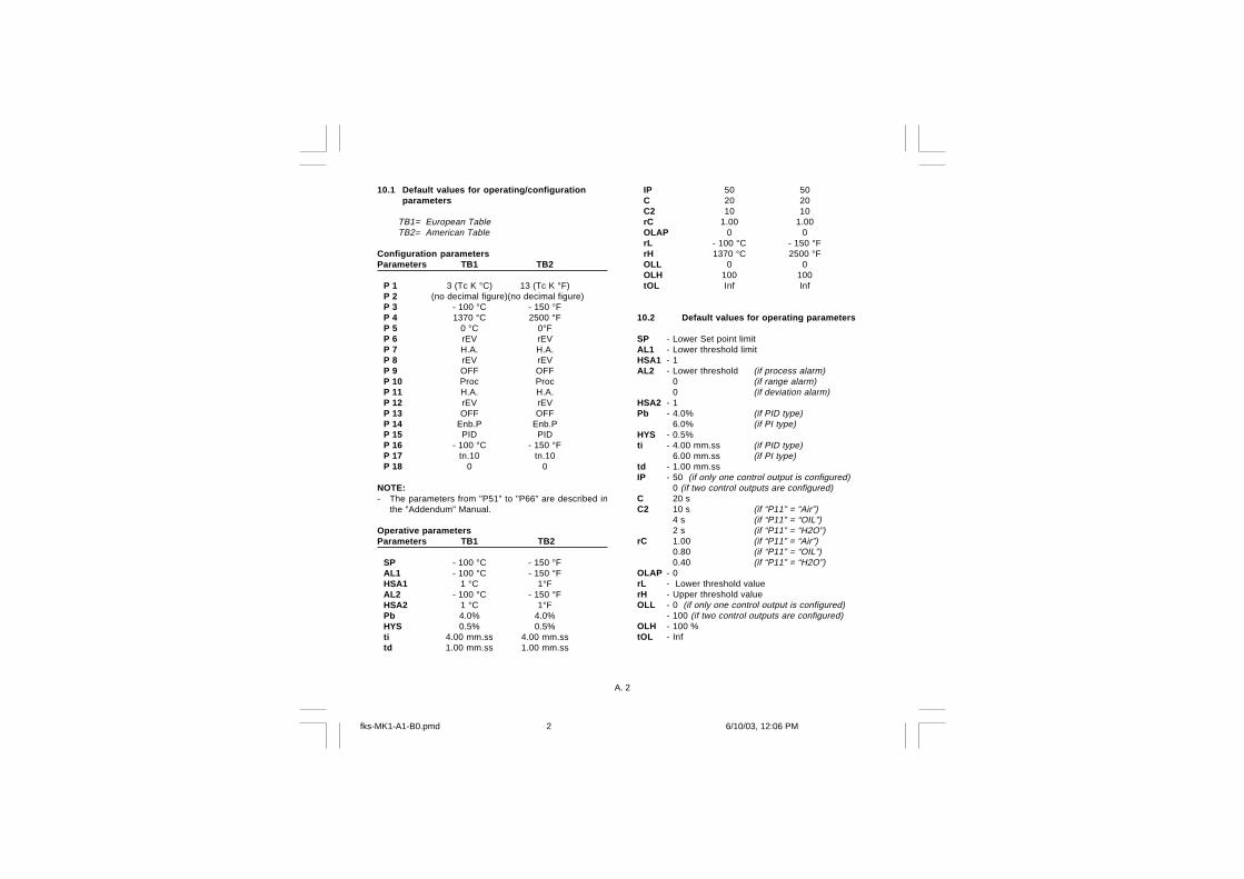
A. 2
10.1 Default values for operating/configurationparameters
TB1= European TableTB2= American Table
Configuration parametersParameters TB1 TB2
P 1 3 (Tc K °C) 13 (Tc K °F)P 2 (no decimal figure)(no decimal figure)P 3 - 100 °C - 150 °FP 4 1370 °C 2500 °FP 5 0 °C 0°FP 6 rEV rEVP 7 H.A. H.A.P 8 rEV rEVP 9 OFF OFFP 10 Proc ProcP 11 H.A. H.A.P 12 rEV rEVP 13 OFF OFFP 14 Enb.P Enb.PP 15 PID PIDP 16 - 100 °C - 150 °FP 17 tn.10 tn.10P 18 0 0
NOTE:- The parameters from "P51" to "P66" are described in
the "Addendum" Manual.
Operative parametersParameters TB1 TB2
SP - 100 °C - 150 °FAL1 - 100 °C - 150 °FHSA1 1 °C 1°FAL2 - 100 °C - 150 °FHSA2 1 °C 1°FPb 4.0% 4.0%HYS 0.5% 0.5%ti 4.00 mm.ss 4.00 mm.sstd 1.00 mm.ss 1.00 mm.ss
IP 50 50C 20 20C2 10 10rC 1.00 1.00OLAP 0 0rL - 100 °C - 150 °FrH 1370 °C 2500 °FOLL 0 0OLH 100 100tOL Inf Inf
10.2 Default values for operating parameters
SP - Lower Set point limitAL1 - Lower threshold limitHSA1 - 1AL2 - Lower threshold (if process alarm)
0 (if range alarm)0 (if deviation alarm)
HSA2 - 1Pb - 4.0% (if PID type)
6.0% (if PI type)HYS - 0.5%ti - 4.00 mm.ss (if PID type)
6.00 mm.ss (if PI type)td - 1.00 mm.ssIP - 50 (if only one control output is configured)
0 (if two control outputs are configured)C 20 sC2 10 s (if “P11” = “Air”)
4 s (if “P11” = “OIL”)2 s (if “P11” = “H2O”)
rC 1.00 (if “P11” = “Air”)0.80 (if “P11” = “OIL”)0.40 (if “P11” = “H2O”)
OLAP - 0rL - Lower threshold valuerH - Upper threshold valueOLL - 0 (if only one control output is configured)
- 100 (if two control outputs are configured)OLH - 100 %tOL - Inf
fks-MK1-A1-B0.pmd 6/10/03, 12:06 PM2
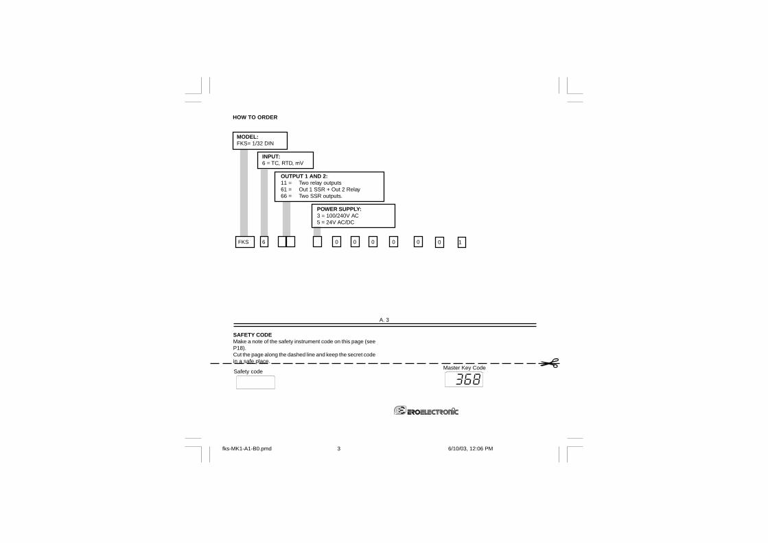
MODEL:FKS= 1/32 DIN
INPUT:6 = TC, RTD, mV
OUTPUT 1 AND 2:11 = Two relay outputs61 = Out 1 SSR + Out 2 Relay66 = Two SSR outputs.
POWER SUPPLY:3 = 100/240V AC5 = 24V AC/DC
FKS 6 0 0 0 0 0
Master Key Code
A. 3
0 1
SAFETY CODEMake a note of the safety instrument code on this page (seeP18).Cut the page along the dashed line and keep the secret codein a safe place.
Safety code
HOW TO ORDER
fks-MK1-A1-B0.pmd 6/10/03, 12:06 PM3

Division of Eurotherm S.r.lvia E. Mattei, 2128100 NovaraItalyTel. +39 0321 481111Fax. +39 0321 481112E-mail [email protected]://www.eroelectronic.com
fks-MK1-A1-B0.pmd 6/10/03, 12:06 PM4