flags pipeline in-line inspection - ppsa-online.com · flags pipeline in-line inspection ... (usd...
TRANSCRIPT
Shell
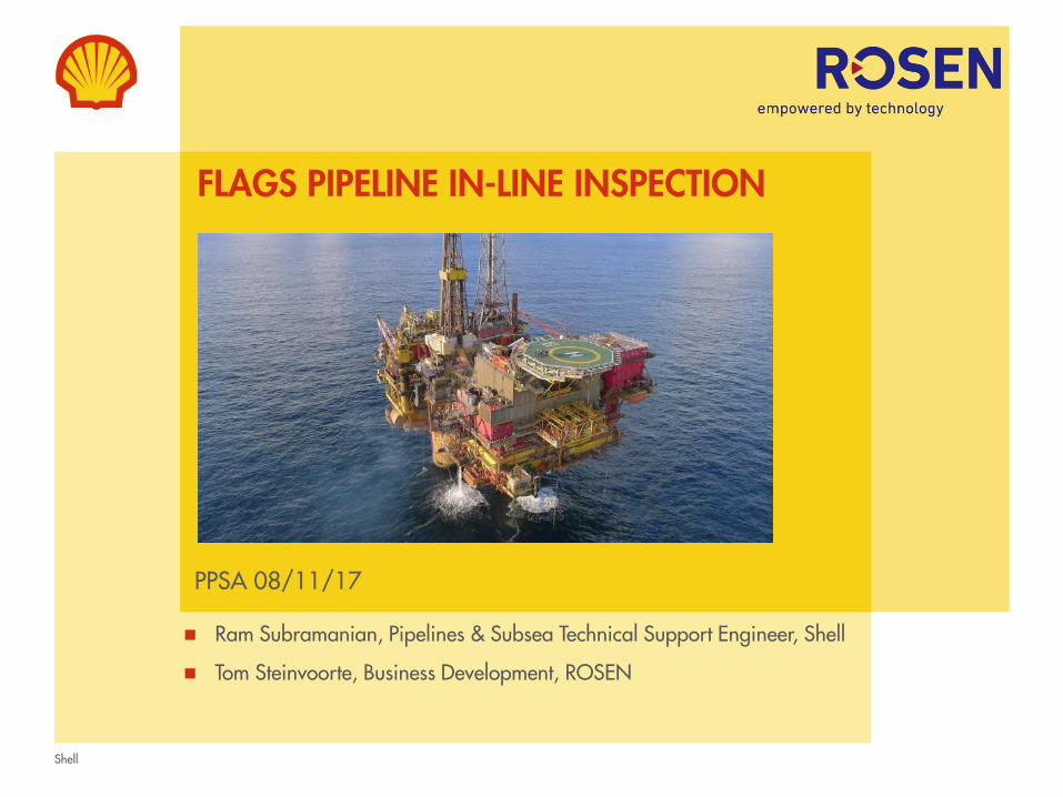
FLAGS PIPELINE IN-LINE INSPECTION
PPSA 08/11/17
Ram Subramanian, Pipelines & Subsea Technical Support Engineer, Shell
Tom Steinvoorte, Business Development, ROSEN

Shell
CONTENTS
• Background
• Key system parameters
• Pigging challenges / solutions
• Factory acceptance test
• Pig model
• Conclusions

Shell
BACKGROUND
FLAGS (Far North Liquids and Associated Gas) pipeline system
• Shell UK operated 36” x 450 km offshore dry gas pipeline that runs from Brent Bravo to St Fergus gas terminal
• Pipeline transports processed gas from UK and Norwegian North Sea platforms
• Operated in dense phase mode between 120 – 135 barg and 15-25 deg C
• Supplies about 15% of UK’s gas consumption and a strategic asset for Shell UK
• Pipeline previously in-line inspected in1991 & 2006.
• Opportunity identified to bring in-line inspection using Magnetic Flux Leakage (MFL) forward to 2017 to:
• Avoid significant complexity, cost and risk associated with subsea pig launch post Brent Bypass Phase 2 (~$$10MM savings)
• Demonstrate integrity to stakeholders to retain and attract future business for Northern Systems and Plant (NSP) asset
Shell
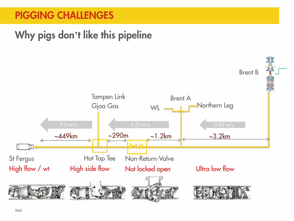
PIGGING CHALLENGES
Brent B
St Fergus
Northern LegBrent A
WL
~3.2km
Hot Tap Tee
~290m
Tampen LinkGjoa Gas
~449km
0.05 m/s0.23 m/s3.5 m/s
~1.2km
Non-Return-Valve
Why pigs don’t like this pipeline
High flow / wt High side flow Not locked open Ultra low flow

Shell
SOLUTIONS
• 4 x sealing capacity / low friction vs normal pig to ensure sealing at ultra low flow*conditions.
• Bespoke design to open and traverse check valve without damage to pig
• Dual module design with each module capable of driving on its own
• Reduced flow through hot tap tee to safeguard mechanical integrity of pig
• Maintain minimum landing pressure at St. Fergus to ensure dense phase gas throughout pigging operations (prevent liquid drop out).
*Shell Group first / potential industry first
Shell
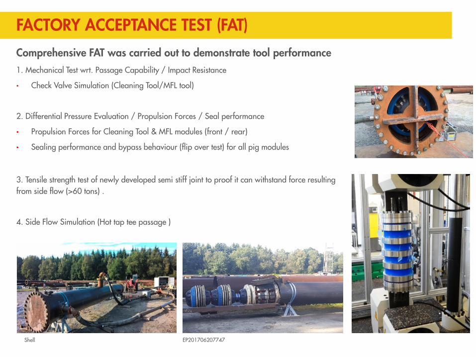
FACTORY ACCEPTANCE TEST (FAT)
Comprehensive FAT was carried out to demonstrate tool performance1. Mechanical Test wrt. Passage Capability / Impact Resistance
• Check Valve Simulation (Cleaning Tool/MFL tool)
2. Differential Pressure Evaluation / Propulsion Forces / Seal performance
• Propulsion Forces for Cleaning Tool & MFL modules (front / rear)
• Sealing performance and bypass behaviour (flip over test) for all pig modules
3. Tensile strength test of newly developed semi stiff joint to proof it can withstand force resulting from side flow (>60 tons) .
4. Side Flow Simulation (Hot tap tee passage )
EP201706207747

Shell
FAT – MFL SIDE FLOW TEST RESULTSSide Flow Simulation ( HTT Passage )
• Passage of both tools with side flow of 300 L/s water @ ~1cm/s
E mv2, vg = 2.87 x vw
for 16” side port, vw = 2.1 m/s, vg = 6 m/s
for 6” side port, vw = 15 m/s, vg = 43 m/s
• Acceptance criteria:
- The foreseen acceptance criterion is two consecutive instrument passages without functional damage.
• Results:
- Two sensors at the 12:00 position found to be “clicked into” a gap underneath the magnets.
- Consequence during actual run would be loss of these two sensors
ROSEN determined this as a design flaw and re-positioned the sensor ring to eliminate this problem. Subsequent test proved this design to be optimal.

Shell
UNISIM DESIGN MODEL SETUP
Key Model Components: FLAGS Pipeline (compas) Gjoa-Vega Pipeline (compas) Tampen Link Pipeline (compas) PI Read (USD spreadsheet) Boundary Conditions (USD spreadsheet) Dash Board (USD spreadsheet)
Benefits of model in this case: Live tracking of pig travel Used as a basis for reducing HTT flowHelps quickly identify anomalous
condition (i.e. stuck pig scenario)Monitor system flows

Shell
SIMULATIONS – LIVE PIG TRACKINGLive Pig Tracking Simulation Trends for Cleaning Pig Run (Brent B flow 1.0-1.1 MMSm3/d)
1. Pig launchat 1064.6 hrsMon 14 Nov 08:40
6. Pig arrivalat launch+60.3 hrsWed 16 Nov 21:00 (model)
20:03 (actual)
7. Max pig velocity3.4-3.5 m/s
2a. Start ramp-down of St Fergusat launch+3 hrs
5b. Start ramp-up of Gjoa-Vegaat launch+15.4 hrs
3. Pig at BA-Tat launch+7.2 hrs
4. Pig at HTTat launch+8.5 hrs
5a. Start ramp-up ofSt Fergusat launch+11.5 hrs
2b. Start ramp-down of Gjoa-Vegaat launch+5 hrs

Shell
PIGGING RESULTSCleaning pig
Overall tool condition good upon receive
Tool removed minimal dust / ferrous debris
Gauge plate had a small deflection of 2mm
likely to be caused by mechanical pig signaller
No further cleaning / gauging runs were
required prior to MFL tool
MFL pig
Tool in good condition upon receive
Ferrous material collected on magnets upon
recovery
Minimal wear to front seals
Sludge type debris received in front of tool
In-line inspection (ILI) data acceptance criteria was
met
ILI final report received with presence of no
significant internal corrosion
Shell
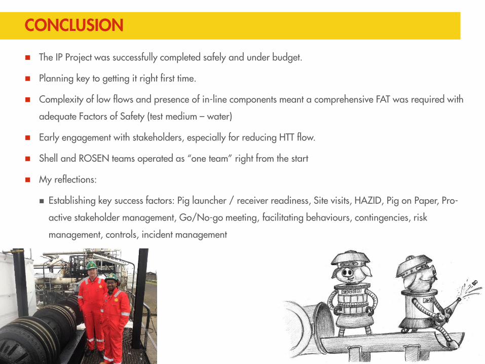
CONCLUSION
The IP Project was successfully completed safely and under budget.
Planning key to getting it right first time.
Complexity of low flows and presence of in-line components meant a comprehensive FAT was required with
adequate Factors of Safety (test medium – water)
Early engagement with stakeholders, especially for reducing HTT flow.
Shell and ROSEN teams operated as “one team” right from the start
My reflections:
Establishing key success factors: Pig launcher / receiver readiness, Site visits, HAZID, Pig on Paper, Pro-
active stakeholder management, Go/No-go meeting, facilitating behaviours, contingencies, risk
management, controls, incident management