flanged series… · mss sp-72 /asme b16.25 • flanged end connections meet asme class 150 valve...
TRANSCRIPT

FLANGED SERIES 2 PIECE FLANGED FULL PORT ½” - 12”F15 - ASME Class 150 | F30 - ASME Class 300

2 | FLANGED SERIES – F15/F30
SECURE MOUNTFlanged Series valves offer ease of automation due to an integrally cast actuator mounting pad which complies with ISO 5211 through 2” valve sizes.
STEM SEALSFlanged Series ½”– 2” valves feature live-loaded, self-adjusting primary and secondary sealing. Utilizing Belleville washers, the stem seal automatically adjusts to compensate for changes in temperature and normal wear. 2½”– 12” valves utilize an independent packing gland which can be easily adjusted without removing mounting hardware or operator. The packing gland is contoured to more uniformly distribute the load across the packing. The primary stem seal is a combination of a thrust washer and a thrust washer protector. An adjustable stem packing creates a secondary seal between the stem and body. The stem packing is composed of RPTFE V-rings as standard – graphite stem packing is standard on all fire safe valves.
BALLFlow-Tek balls are precision machined and mirror finished for bubble-tight shut off and less operating torque. As an added safety feature, a hole in the stem slot of each ball equalizes pressure between the body cavity and the line media flow.
BODY½”– 4” valve bodies are investment cast and solution annealed/normalized for the highest quality and added strength. All body castings are marked with a foundry heat number for full traceability. Carbon steel bodies are phosphate coated for increased corrosion resistance.
SEATFlow-Tek’s seat design ensures bi-directional, bubble-tight sealing with low operating torque. All resilient seats feature relief slots or seat O.D. clearance to relieve pressure past the upstream seat, and positive preloading to ensure low pressure/vacuum sealing.
F L A N G E D S E R I E S B A L L VA LV E SFlow-Tek’s F15/F30 Flanged Series ball valves feature a floating ball design for low torque and increased cycle life. As standard, large size valves feature trunnion-type ball support. These rugged ball valves are ideal for industrial applications.
Body 2 PieceFull Port ½” through 12”
Materials Stainless Steel, Carbon Steel & Special Alloys
Pressure Ratings F15: ASME Class 150 F30: ASME Class 300
FLANGED SERIES – F15/F30 | 3
Nut and Tab Lock Washer
Stem
Belleville Washers
Tek-Fil® Thrust WasherPEEK Protector
Anti-Static Devices
Packing GlandPEEK ProtectorStem Packing
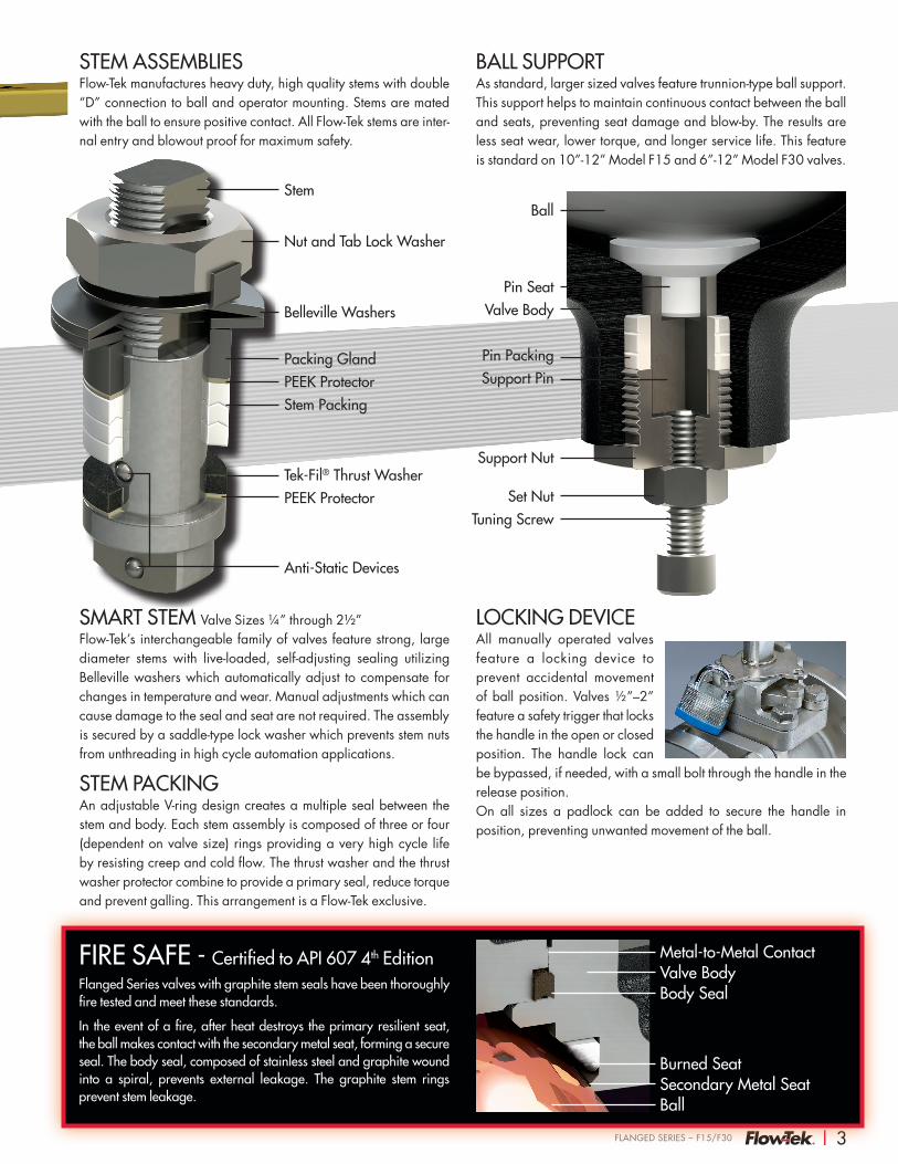
STEM ASSEMBLIESFlow-Tek manufactures heavy duty, high quality stems with double “D” connection to ball and operator mounting. Stems are mated with the ball to ensure positive contact. All Flow-Tek stems are inter-nal entry and blowout proof for maximum safety.
SMART STEM Valve Sizes ¼” through 2½”Flow-Tek’s interchangeable family of valves feature strong, large diameter stems with live-loaded, self-adjusting sealing utilizing Belleville washers which automatically adjust to compensate for changes in temperature and wear. Manual adjustments which can cause damage to the seal and seat are not required. The assembly is secured by a saddle-type lock washer which prevents stem nuts from unthreading in high cycle automation applications.
STEM PACKINGAn adjustable V-ring design creates a multiple seal between the stem and body. Each stem assembly is composed of three or four (dependent on valve size) rings providing a very high cycle life by resisting creep and cold flow. The thrust washer and the thrust washer protector combine to provide a primary seal, reduce torque and prevent galling. This arrangement is a Flow-Tek exclusive.
LOCKING DEVICE All manually operated valves feature a locking device to prevent accidental movement of ball position. Valves ½”–2” feature a safety trigger that locks the handle in the open or closed position. The handle lock can be bypassed, if needed, with a small bolt through the handle in the release position. On all sizes a padlock can be added to secure the handle in position, preventing unwanted movement of the ball.
Ball
Pin PackingSupport Pin
Support Nut
Pin Seat Valve Body
Set NutTuning Screw
BALL SUPPORTAs standard, larger sized valves feature trunnion-type ball support. This support helps to maintain continuous contact between the ball and seats, preventing seat damage and blow-by. The results are less seat wear, lower torque, and longer service life. This feature is standard on 10”-12” Model F15 and 6”-12” Model F30 valves.
FIRE SAFE - Certified to API 607 4th EditionFlanged Series valves with graphite stem seals have been thoroughly fire tested and meet these standards.
In the event of a fire, after heat destroys the primary resilient seat, the ball makes contact with the secondary metal seat, forming a secure seal. The body seal, composed of stainless steel and graphite wound into a spiral, prevents external leakage. The graphite stem rings prevent stem leakage.
Metal-to-Metal ContactValve BodyBody Seal
Burned SeatSecondary Metal SeatBall

4 | FLANGED SERIES – F15/F30
STEAM SERVICE PRESSURE RATINGS: WSP TFM Seats Tek-Fil Seats PEEK Seats
PSI °F PSI °F PSI °F
Class 150 150 365 190 383 170 374
Class 300 150 365 425 454 425 454
Vacuum service to 29.9 inches Hg. gauge.
SEAT SELECTION A wide range of seat materials are available to meet most applications. The standard seat is TFM 1600. Options include:
• RPTFE
• Stainless Steel/PTFE (50/50)
• UHMWPE
• Virgin PTFE
• PEEK
• Tek-Fil® (carbon/graphite filled TFM)
• Full metal seats
• Cavity Fillers
PEEK seats offer high pressure/temperature capability. Tek-Fil® seats offer reduced torque in high temperature, high cycle, and steam service applications. TFM 1600 seats offer the exceptional chemical resistance of PTFE plus lower porosity and permeability, improved temperature range and reduced valve torques.
PRESSURE/TEMPERATURE
1000-50 200 300 400 500 600 700
800
700
600
500
400
300
200
100
Pres
sure
(psi
)
ASME Class 150
ASME Class 300
RPTFE
PEEK
TFM 1600 & 50/50
Tek-Fil®
Temperature (°F)Carbon steel valves limited to -20°F
SPECIFICATIONS • Valve sizes ¼” through 12”
• Design meets MSS-SP-110
• Threaded end connections meet ASME B1.20.1 NPT
• Socket weld end connections meet ASME B16.11
• Butt weld end (Schedule 40) connections meet
MSS SP-72 /ASME B16.25
• Flanged end connections meet ASME Class 150
Valve body and end cap connections are high quality investment cast and solution annealed/normalized. Body and end cap wall thickness meets ASME B16.34.
Valve stems are blow-out proof for maximum safety and meet ASME B16.34 specification.
All valves are factory tested to MSS SP-72 and API 598.
SPECIAL OPTIONS/SERVICESCavity Fillers Media Containment UnitsSpring Return Handles NACEVented Balls Polished InternalsCharacterized Balls Special CleaningChlorine Service Silicone Free

FLANGED SERIES – F15/F30 | 5
184
5
3022
21
20
27
17
16
1015
14
131211
5
1
84
34
6
72
1112
1410151819
25
29
28
23
24
26
3
6
7
2
½” – 2” VALVESCarbon steel bodies on valve sizes ½” – 4” are black phosphate coated.
All stainless steel bodies are solution annealed/normalized.
2½” – 12” VALVESBall support is included on 10”-12” F15 valves and 6”-12” F30 valves.
25 2½” – 4” Valves
25 6”and 8” Valves
COMPONENTS & MATERIALS ITEM/NAME STAINLESS STEEL CARBON STEEL QTY.
1. Body ASTM A351 Gr CF8M
ASTM A216 Gr WCB 1
2. End Cap ASTM A351 Gr CF8M
ASTM A216 Gr WCB 1
3. Ball ASTM A351 Gr CF8M 1
4. Seat TFM 1600 2
5. Stem ASTM A479 Type 316 1
6. Body Seal Spiral Wound (316/Graphite) 1
7. Body Nut ASTM A194 Gr 8 *
8. Body Stud ASTM A193 B8 ASTM A193 B7 *
9. Anti-Static Device SS304 2
10. Packing Protector PEEK 1
11. Thrust Washer Protector PEEK 1
12. Thrust Washer Tek-Fil 1
13. Stem Bearing 15% RPTFE 1
14. Stem Packing RPTFE/Graphite 3/1
15. Packing Gland ASTM A167 Type 304 1
16. Packing Follower
ASTM A351 Gr CF8M
ASTM A216 Gr WCB 1
17. Gland Bolt SS304 2
18. Belleville Washer SS301 2
19. Tab Lock Washer SS304 1
20. Travel Stop Housing CF8M WCB 1
21. Housing Bolt SS304 Alloy Steel 4
22. Travel Stop SS304 Zinc Plated Carbon Steel 1
23. Travel Stop Sleeve ASTM A167 Type 304 1
24. Travel Stop Bolt SS304 1
25. Handle SS304/**Ductile Iron 1
26. Lock Nut ASTM A167 Type 304 2
27. Handle Bolt Carbon Steel 1
28. Handle Sleeve Vinyl through 2” 1
29. Locking Device SS304 130. Snap Ring Nickel Plated Carbon Steel 2
*Quantity depends on valve size. **2½” and larger valves.
Flow-Tek offers the seat, body seal, thrust washer and stem packing as recommended spare parts. These parts are available as a packaged repair kit.

6 | FLANGED SERIES – F15/F30
Model F15 – Class 150
Size A øB C C1 D E øF øS N / øT Cv Torque* Weight
INC
HES
1/2 4.25 0.59 2.88 1.54 6.50 1.79 3.50 2.38 4 x 0.62 32
LBS-
IN
36
LBS
43/4 4.62 0.79 2.97 1.67 6.50 2.01 3.88 2.75 4 x 0.62 60 65 51 5.00 0.98 3.41 2.05 7.87 2.13 4.25 3.12 4 x 0.62 105 95 10
1-1/2 6.50 1.49 4.20 2.60 9.84 2.76 5.00 3.88 4 x 0.62 275 230 142 7.00 1.97 4.53 2.95 10.43 3.07 6.00 4.75 4 x 0.75 500 390 20.5
MILL
IMET
ERS 15 108.0 15.0 73.25 39.0 165.0 45.5 88.9 60.5 4 x 15.8 28
Nm
4
KG
220 117.0 20.0 75.40 42.4 165.0 51.0 98.6 69.9 4 x 15.8 52 7 225 127.0 24.9 86.69 52.0 199.9 54.0 108.0 79.0 4 x 15.8 91 11 4.5
40 165.0 37.9 106.60 66.0 249.9 70.0 127.0 98.6 4 x 15.8 238 26 650 177.8 50.0 115.01 74.9 264.9 78.0 152.0 120.7 4 x 19.0 433 44 9
Model F30 – Class 300
Size A øB C C1 D E øF øS N / øT Cv Torque* Weight
INC
HES
1/2 5.50 0.59 2.92 1.57 6.50 2.44 3.75 2.62 4 x 0.62 32
LBS-
IN
40
LBS
53/4 6.00 0.79 2.97 1.67 6.50 2.72 4.62 3.25 4 x 0.75 60 70 71 6.50 0.98 3.41 2.05 7.87 2.91 4.88 3.50 4 x 0.75 105 108 10
1-1/2 7.50 1.49 4.04 2.60 9.84 3.27 6.12 4.50 4 x 0.88 275 270 192 8.50 1.97 4.53 2.95 10.43 3.94 6.50 5.00 8 x 0.75 500 445 25
MILL
IMET
ERS 15 139.7 15.0 74.23 39.9 165.0 62.0 95.0 66.6 4 x 15.8 28
Nm
5
KG
220 152.0 20.0 75.40 42.0 165.0 69.0 117.0 82.6 4 x 19.0 52 8 325 165.0 24.9 86.61 52.0 199.9 73.9 124.0 88.9 4 x 19.0 91 12 5
40 190.5 37.9 102.50 66.0 249.9 83.0 155.5 114.0 4 x 22.0 238 31 950 215.9 50.0 115.06 74.9 264.9 100.0 165.0 127.0 8 x 19.0 433 50 11
Face to Face dimensions meet ASME B16.10 long pattern and short pattern (sizes 1/2 " thru 2").*Torque at maximum rated pressure, clean water, TFM 1600 seating material. Other seat materials exhibit different torques.Please refer to TB 1005 for specific torques.
DIMENSIONS – Secure Mount
Size H J F0 BCDIA. K L M øP U
UNC
INC
HES
1/2 1.17 1.17 F04 1.65 0.31 0.61 0.25 0.37 #10-243/4 1.17 1.17 F04 1.65 0.31 0.61 0.25 0.37 #10-241 1.39 1.39 F05 1.97 0.43 0.82 0.31 0.43 1/4-20
1-1/2 1.95 1.95 F07 2.76 0.55 0.95 0.37 0.62 5/16-182 1.95 1.95 F07 2.76 0.55 0.95 0.37 0.62 5/16-18
MILL
IMET
ERS 15 29.7 29.7 F04 41.9 7.9 15.5 6.0 9.4 #10-24
20 29.7 29.7 F04 41.9 7.9 15.5 6.0 9.4 #10-2425 35.0 35.0 F05 50.0 10.9 20.8 7.9 10.9 1/4-20
40 49.5 49.5 F07 70.0 14.0 24.0 9.0 15.8 5/16-1850 49.5 49.5 F07 70.0 14.0 24.0 9.0 15.8 5/16-18
Ux4
M
J
K
L
øP H
F15/F30 DIMENSIONS ½" – 2" VALVES (15mm - 50mm)
AE
D
N-øTC
øF
C1
øSøB

FLANGED SERIES – F15/F30 | 7
Model F15 – Class 150
Size A øB C C1 D E øF øS N / øT Cv Torque* Weight
INC
HES
2-1/2 7.50 2.56 6.63 3.39 15.35 3.08 7.00 5.50 4 x 0.75 780
LBS-
IN
500
LBS
363 8.00 2.99 6.92 3.66 15.35 3.74 7.50 6.00 4 x 0.75 1,150 650 454 9.00 3.99 7.59 4.39 15.35 4.47 9.00 7.50 8 x 0.75 2,100 1,505 656 15.50 5.98 12.38 7.17 15.35 7.62 11.00 9.50 8 x 0.88 5,000 3,250 1578 18.00 7.87 12.66 7.60 38.98 8.35 13.50 11.75 8 x 0.88 9,600 4,750 290
10 21.00 9.84 14.80 9.88 38.98 10.47 16.00 14.25 12 x 1.00 15,000 13,700 50012 24.00 11.81 16.37 11.46 38.98 12.01 19.00 17.00 12 x 1.00 21,000 19,700 700
MILL
IMET
ERS
65 190.5 65.0 168.40 86.0 389.9 78.0 177.8 139.7 4 x 19.0 675
Nm
56
KG
1680 203.0 76.0 175.65 93.0 389.9 95.0 190.5 152.0 4 x 19.0 995 73 20100 228.6 101.0 192.90 111.5 389.9 113.5 228.6 190.5 8 x 19.0 1,817 170 29.5150 393.7 151.9 314.55 182.0 389.9 193.6 279.0 241.0 8 x 22.0 4,325 367 71200 457.0 199.9 321.58 193.0 990.0 212.0 342.9 298.5 8 x 22.0 8,304 537 132250 533.0 249.9 375.85 251.0 990.0 265.9 406.0 362.0 12 x 25.0 12,975 1,548 227300 609.6 300.0 415.85 291.0 990.0 305.0 482.6 431.8 12 x 25.0 18,165 2,226 318
Model F30 – Class 300
Size A øB C C1 D E øF øS N / øT Cv Torque* Weight
INC
HES
2-1/2 9.50 2.56 6.55 3.39 15.35 4.18 7.50 5.88 8 x 0.88 780
LBS-
IN
600LB
S44
3 11.12 2.99 6.85 3.72 15.35 5.57 8.25 6.62 8 x 0.88 1,150 850 614 12.00 3.99 7.56 4.35 15.35 5.96 10.00 7.88 8 x 0.88 2,100 2,600 966 15.88 5.98 12.37 7.19 38.98 7.60 12.50 10.62 12 x 0.88 5,000 5,300 2438 19.75 7.87 13.82 8.64 38.98 9.33 15.00 13.00 12 x 1.00 9,600 7,600 43010 22.38 9.84 - 9.69 38.98 11.18 17.50 15.25 16 x 1.12 15,000 17,800 61012 25.50 11.81 - 11.26 38.98 12.80 20.50 17.75 16 x 1.25 21,000 24,800 950
MILL
IMET
ERS
65 241.0 65.0 166.40 86.0 389.9 106.0 190.5 149.0 8 x 22.0 675
Nm
68
KG
2080 282.5 76.0 173.90 94.5 389.9 141.5 209.6 168.0 8 x 22.0 995 96 27.7100 304.8 101.0 192.05 110.5 389.9 151.0 254.0 200.0 8 x 22.0 1,817 294 44150 403.0 151.9 314.20 182.6 990.0 193.0 317.5 269.8 12 x 22.0 4,325 599 110200 501.7 199.9 351.05 219.5 990.0 237.0 381.0 330.0 12 x 25.0 8,304 859 195250 568.5 249.9 - 246.0 990.0 284.0 444.5 387.0 16 x 28.5 12,975 2,011 277300 647.7 300.0 - 286.0 990.0 325.0 520.7 450.9 16 x 31.8 18,165 2,802 431
1 For 8” F30: K=1.61, L=3.42 2 For 10” F30: L=3.82, P=2.165NOTE 1: Ball Support as shown on Page 2 is included on 10”-12” F15 and 6”-12” F30 valves.NOTE 2: 2½”, 3” & 4” valves feature a NAMUR stem slot for ease of limit switch mounting.Face to Face dimensions meet ASME B16.10 long pattern in all sizes and short pattern sizes up to 4" F15 and up to 6" F30.*Torque at maximum rated pressure, clean water, TFM 1600 seating material. Other seat materials exhibit different torques.Please refer to TB 1005 for specific torques.
DIMENSIONS – Secure Mount
Size H J F0 BCDIA. K L M øP U
UNC
INC
HES
2-1/2 - 4 3.54 1.87 F10 — 1.75 3.10 0.67 1.10 1/2-136 3.37 3.37 F12 4.77 1.61 3.58 1.02 1.71 1/2-1381 3.37 3.37 F12 4.77 2.131 3.581 1.02 1.71 1/2-13
10-122 4.53 4.53 F16 6.40 2.15 3.862 1.38 1.972 5/8-11
MILL
IMET
ERS 65 - 100 89.9 47.5 F10 — 44.5 78.7 17.0 27.9 1/2-13
150 85.6 85.6 F12 121.0 40.9 90.9 25.9 43.0 1/2-13200 85.6 85.6 F12 121.0 54.0 90.9 25.9 43.0 1/2-13
250-300 115.0 115.0 F16 162.6 54.6 98.0 35.0 50.0 5/8-11
F15/F30 DIMENSIONS 2½" – 12" VALVES (65mm - 300mm)
Ux4
M
K
øP
L
H
J
NOTE 1
A
D
N-øT
øB øFøS
C1
C
E

Subsidiary of BRAY INTERNATIONAL, Inc.8323 N. Eldridge Pkwy #100 Houston, Texas 77041
832.912.2300 Fax: 832.912.2301 www.flow-tek.com
Global manufacturing, service around the cornerTo serve you locally, each region maintains a
factory certified sales and service network
for all Bray International products.
p FLOW-TEK - USA - Office & Manufacturing
q WORLD HEADQUARTERS - BRAY INTERNATIONAL , INC. - USA
All statements, technical information, and recommendations in this bulletin are for general use only. Consult Flow-Tek representatives or factory for the specific requirements and material selection for your intended application. The right to change or modify product design or product without prior notice is reserved.
Flow-Tek® is a registered trademark of Flow-Tek, Inc.© 2015 Flow-Tek, Inc. All rights reserved.
F-2400_EN_F15/30_10_2015