flanges and fittings flange a - ideal vacuum · flange fittings with the appropriate collar...
TRANSCRIPT
Flange aISO-KF, ISO-K, ISO-F, CF
Flanges and Fittings
280.00.02Excerpt from the Leybold Full Line Catalog 2018Catalog Part Flanges and Fittings
leyboldLeybold Full Line Catalog 2018 - Flanges and Fittings2
leyboldLeybold Full Line Catalog 2018 - Flanges and Fittings2 leybold Leybold Full Line Catalog 2018 - Flanges and Fittings 3
Flanges and Fittings
General
Introduction . . . . . . . . . . . . . . . . . . . . . . . . . . . . . . . . . . . . . . . . . . . . . . . . . . . . . . . . . . . . . . . . . . . . . . . . . . . 4
These Arguments Prove Leybold’s QUALITY . . . . . . . . . . . . . . . . . . . . . . . . . . . . . . . . . . . . . . . . . . . . . . . . . . 5
Materials . . . . . . . . . . . . . . . . . . . . . . . . . . . . . . . . . . . . . . . . . . . . . . . . . . . . . . . . . . . . . . . . . . . . . . . . . . . . . 6
The Right Connection from Leybold . . . . . . . . . . . . . . . . . . . . . . . . . . . . . . . . . . . . . . . . . . . . . . . . . . . . . . . . 7
Flange Connections . . . . . . . . . . . . . . . . . . . . . . . . . . . . . . . . . . . . . . . . . . . . . . . . . . . . . . . . . . . . . . . . . . . . . 8
Products
ISO-KF Flange Fittings and Components . . . . . . . . . . . . . . . . . . . . . . . . . . . . . . . . . . . . . . . . . . . . . . . . . 10
Version for the North and South American Continent . . . . . . . . . . . . . . . . . . . . . . . . . . . . . . . . . . . . . . . . . 29
ISO-K Clamp Flange Fittings and Components . . . . . . . . . . . . . . . . . . . . . . . . . . . . . . . . . . . . . . . . . . . . 36
Version for the North and South American Continent . . . . . . . . . . . . . . . . . . . . . . . . . . . . . . . . . . . . . . . . . 49
ISO-F and DIN EN 1092-1 Fixed Flange Fittings and Components . . . . . . . . . . . . . . . . . . . . . . . . . . . . . 50
ISO-F Fixed Flange Fittings and Components . . . . . . . . . . . . . . . . . . . . . . . . . . . . . . . . . . . . . . . . . . . . . . 51
DIN EN 1092-1 Fixed Flange Fittings and Components . . . . . . . . . . . . . . . . . . . . . . . . . . . . . . . . . . . . . . . 55
Version for the North and South American Continent . . . . . . . . . . . . . . . . . . . . . . . . . . . . . . . . . . . . . . . . . 56
CF Flanges Fittings and Components . . . . . . . . . . . . . . . . . . . . . . . . . . . . . . . . . . . . . . . . . . . . . . . . . . . . 58
Observation Windows for Vacuum Systems . . . . . . . . . . . . . . . . . . . . . . . . . . . . . . . . . . . . . . . . . . . . . . . 72
ISO-KF / ISO-K Observation Windows . . . . . . . . . . . . . . . . . . . . . . . . . . . . . . . . . . . . . . . . . . . . . . . . . . . 73
CF Observation Windows . . . . . . . . . . . . . . . . . . . . . . . . . . . . . . . . . . . . . . . . . . . . . . . . . . . . . . . . . . . . . 74
For information on electrical, rotary/linear motion and liquid feedthroughs, please refer to Catalog Part “Feedthroughs”.
Contents
leyboldLeybold Full Line Catalog 2018 - Flanges and Fittings4
General to Flanges and Fittings
Introduction
According to DIN 28 400, the term “Ultra-high Vacuum (UHV)” designates the pressure range below 10-7 mbar .
Several physical quantities, such as mean free path, monolayer time, flow density of the particles impinging on the walls, leak rate and the degassing rate are of significance in the charac ter-ization of this pressure range . For the definitions of these quantities refer to technical publications on this subject .
In order to attain or maintain pressures below 10-7 mbar, the following pre-con-ditions must be met:
- The vapor pressure of the pump fluid or lubricant should be in accordance with the desired ultimate pressure
- the leak and degassing rates of the entire apparatus including its instal-lations must be extremely low .
Generally, both leak rate and back-streaming effects through the pump can be kept at sufficiently low levels by using suitable UHV sealing materials and pumps .
Advantages to the User
- Stabilized Leybold knife-edge
- High reliability
- Special knife edge profiles ensure the highest degree of leak tightness
- Flange connection can be baked out up to 450 °C (842 °F)
- Easy to assemble, helium-tight
- Symmetrical flange connection
- Equal sealing profiles
- Small outside diameter with respect to the nominal width
- Can be joined by welding or brazing using any desired process, also with other nickel chromium steel grades
- For use either with a flat gasket made of OFHC copper (oxygen-free) or FPM (FKM) O-ring
- Self-centering
- Fixed and rotary flanges in almost any size
However, a sufficiently low out gassing rate can only be achieved by baking out the entire apparatus at tempera-tures of about 300 °C (572 °F) for a longer period of time . It is only under these condi tions that the mono-layers of atoms or molecules, which attach quite firmly to the surfaces of the vacu-um apparatus including its installations, are desorbed .
Consequently, components for UHV systems are generally made of stainless steel . Metal gaskets, ceramic feedthroughs and bakeable obser-vation windows are used exclusi vely .
For applications in the extreme UHV range (XHV) the outgassing rate of the CF flanges and the UHV components can be reduced by about two orders of magnitude by a special degassing process .
The high standard of development and manufacture combined with the use of high quality materials guarantee that UHV components from Leybold Vacuum are able to meet even the most demanding requirements .
leyboldLeybold Full Line Catalog 2018 - Flanges and Fittings4 leybold Leybold Full Line Catalog 2018 - Flanges and Fittings 5
These Arguments Prove Leybold’s QUALITY- Availability of all components at
short notice
- Worldwide advice at any time to answer your questions relating to vacuum systems
- Utilization of most advanced manu-facturing methods
- Environment-friendly cleaning baths with complete waste disposal and recycling facilities
- Environment-friendly and secure packaging
- Total Quality Management methods during all processing stages
- Controlled material quality
- Compatible to your existing flanges of the same system
- Highly leak-tight down to leak rates of 1 x 10⁻⁹ mbar x l/s; all components are subjected to a helium leak test
- Low outgassing rates of the materials through - choice of the right material quality, especially for vacuum apparatus - excellent cleaning methods
- Documentation available for all components
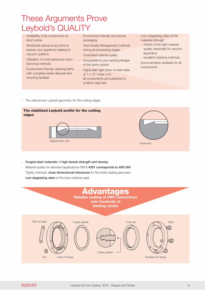
- The well-proven Leybold geometry for the cutting edges
The stabilized Leybold profile for the cutting edges
Diagrammatic viewPartial view
- Forged steel materials of high tensile strength and density
- Material quality for standard applications DIN 1.4301 corresponds to AISI 304
- Tightly checked, close dimensional tolerances for the entire sealing geometry
- Low degassing rates of the tube material used
Nut
Bolt nut plate
Fixed CF flange
Copper gasket
Copper gasket
Inner part Bolts
Rotatable CF flange
AdvantagesReliable sealing of UHV connections
over hundreds of heating cycles
leyboldLeybold Full Line Catalog 2018 - Flanges and Fittings6
General
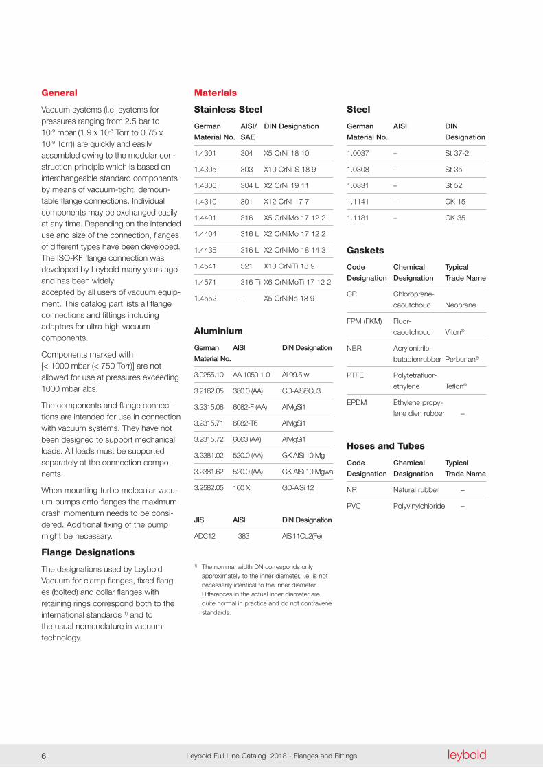
Vacuum systems (i .e . systems for pressures ranging from 2 .5 bar to 10-9 mbar (1 .9 x 10-3 Torr to 0 .75 x 10-9 Torr)) are quickly and easily as sembled owing to the modular con-struction principle which is based on interchangeable standard components by means of vacuum-tight, demoun-table flange connections . Individual components may be exchanged easily at any time . Depending on the in tended use and size of the connection, flanges of different types have been developed . The ISO-KF flange connection was developed by Leybold many years ago and has been widely accepted by all users of vacuum equip-ment . This catalog part lists all flange connections and fittings including adaptors for ultra-high vacuum components .
Components marked with [< 1000 mbar (< 750 Torr)] are not allowed for use at pressures exceeding 1000 mbar abs .
The components and flange connec-tions are intended for use in connection with vacuum systems . They have not been designed to support mechanical loads . All loads must be sup ported separately at the connection compo-nents .
When mounting turbo molecular vacu-um pumps onto flanges the maximum crash momentum needs to be consi-dered . Additional fixing of the pump might be necessary .
Flange Designations
The designations used by Leybold Vacuum for clamp flanges, fixed flang-es (bolted) and collar flanges with retaining rings correspond both to the international standards 1) and to the usual nomenclature in vacuum technology .
Materials
Stainless Steel
German AISI/ DIN Designation
Material No. SAE
1 .4301 304 X5 CrNi 18 10
1 .4305 303 X10 CrNi S 18 9
1 .4306 304 L X2 CrNi 19 11
1 .4310 301 X12 CrNi 17 7
1 .4401 316 X5 CrNiMo 17 12 2
1 .4404 316 L X2 CrNiMo 17 12 2
1 .4435 316 L X2 CrNiMo 18 14 3
1 .4541 321 X10 CrNiTi 18 9
1 .4571 316 Ti X6 CrNiMoTi 17 12 2
1 .4552 – X5 CrNiNb 18 9
Aluminium
German AISI DIN Designation
Material No.
3 .0255 .10 AA 1050 1-0 Al 99 .5 w
3 .2162 .05 380 .0 (AA) GD-AlSi8Cu3
3 .2315 .08 6082-F (AA) AlMgSi1
3 .2315 .71 6082-T6 AlMgSi1
3 .2315 .72 6063 (AA) AlMgSi1
3 .2381 .02 520 .0 (AA) GK AISi 10 Mg
3 .2381 .62 520 .0 (AA) GK AlSi 10 Mgwa
3 .2582 .05 160 X GD-AlSi 12
JIS AISI DIN Designation
ADC12 383 AlSi11Cu2(Fe)
1) The nominal width DN corresponds only approximately to the inner diameter, i .e . is not necessarily identical to the inner diameter . Differences in the actual inner diameter are quite normal in practice and do not contravene standards .
Steel
German AISI DIN
Material No. Designation
1 .0037 – St 37-2
1 .0308 – St 35
1 .0831 – St 52
1 .1141 – CK 15
1 .1181 – CK 35
Gaskets
Code Chemical Typical
Designation Designation Trade Name
CR Chloroprene-
caoutchouc Neoprene
FPM (FKM) Fluor-
caoutchouc Viton®
NBR Acrylonitrile-
butadienrubber Perbunan®
PTFE Polytetrafluor-
ethylene Teflon®
EPDM Ethylene propy-
lene dien rubber –
Hoses and Tubes
Code Chemical Typical
Designation Designation Trade Name
NR Natural rubber –
PVC Polyvinylchloride –
leyboldLeybold Full Line Catalog 2018 - Flanges and Fittings6 leybold Leybold Full Line Catalog 2018 - Flanges and Fittings 7
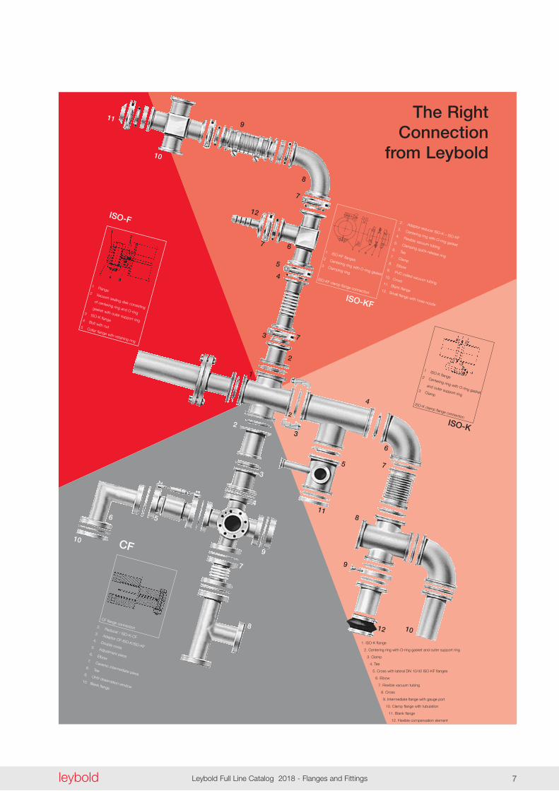
The Right Connection
from Leybold
ISO-K
1 ISO-K flange 2 Centering ring with O-ring gasket
and outer support ring 3 Clamp
ISO-K clamp flange connection
ISO-F
1 Flange 2 Vacuum sealing disk consisting
of centering ring and O-ring
gasket with outer support ring
3 ISO-K flange 4 Bolt with nut 5 Collar flange with retaining ring
ISO-KF
2 . Adaptor reducer ISO-K – ISO-KF
3 . Centering ring with O-ring gasket
4 . Flexible vacuum tubing5 . Clamping quick-release ring
6 . Tee7 . Clamp
8 . Elbow9 . PVC coiled vacuum tubing
10 . Cross11 . Blank flange12 . Small flange with hose nozzle
1 ISO-KF flanges 2 Centering ring with O-ring gasket
3 Clamping ring
ISO-KF clamp flange connection
CF
2 . Reducer / ISO-K-CF3 . Adaptor CF-ISO-K/ISO-KF
4 . Double cross 5 . Adjustment piece6 . Elbow7 . Ceramic intermediate piece
8 . Tee9 . UHV observation window
10 . Blank flange
1 . ISO-K flange
2 . Centering ring with O-ring gasket and outer support ring
3 . Clamp
4 . Tee
5 . Cross with lateral DN 10/40 ISO-KF flanges
6 . Elbow
7 . Flexible vacuum tubing
8 . Cross
9 . Intermediate flange with gauge port
10 . Clamp flange with tubulation
11 . Blank flange
12 . Flexible compensation element
CF flange connection
1
2
3
4
5
6
7
7
7
8
9
10
11
12
2
3
4
56
10
7
8
9
2
3
4
5
6
7
8
9
10
11
12
14
2
13
leyboldLeybold Full Line Catalog 2018 - Flanges and Fittings8
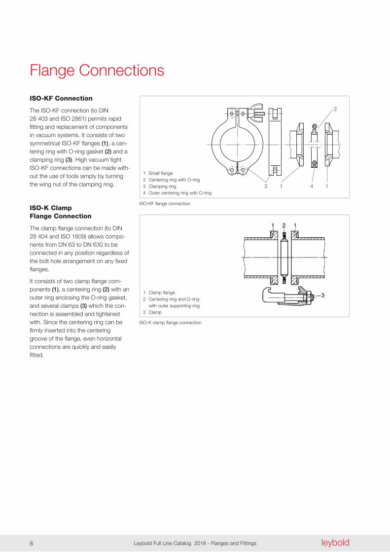
Flange Connections
ISO-KF Connection
The ISO-KF connection (to DIN 28 403 and ISO 2861) permits rapid fitting and replacement of components in vacuum systems . It consists of two symmetrical ISO-KF flanges (1), a cen-tering ring with O-ring gasket (2) and a clamping ring (3) . High vacuum tight ISO-KF connections can be made with-out the use of tools simply by turn ing the wing nut of the clamping ring .
ISO-K Clamp Flange Connection
The clamp flange connection (to DIN 28 404 and ISO 1609) allows compo-nents from DN 63 to DN 630 to be connected in any position regardless of the bolt hole arrangement on any fixed flanges .
It consists of two clamp flange com - ponents (1), a centering ring (2) with an outer ring enclosing the O-ring gasket, and several clamps (3) which the con-nection is assembled and tightened with . Since the centering ring can be firmly inserted into the centering groove of the flange, even horizontal connections are quickly and easily fitted .
ISO-KF flange connection
1 Small flange2 Centering ring with O-ring3 Clamping ring4 Outer centering ring with O-ring
ISO-K clamp flange connection
1 Clamp flange2 Centering ring and O-ring with outer supporting ring3 Clamp
leyboldLeybold Full Line Catalog 2018 - Flanges and Fittings8 leybold Leybold Full Line Catalog 2018 - Flanges and Fittings 9
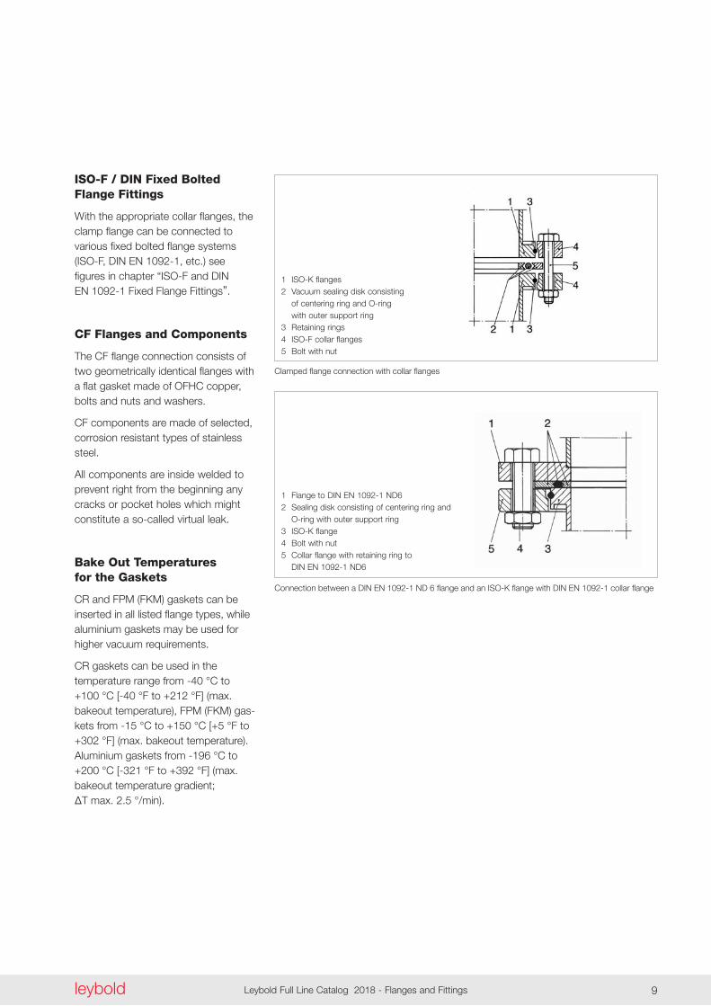
Clamped flange connection with collar flanges
1 ISO-K flanges2 Vacuum sealing disk consisting
of centering ring and O-ring with outer support ring
3 Retaining rings4 ISO-F collar flanges5 Bolt with nut
ISO-F / DIN Fixed Bolted Flange Fittings
With the appropriate collar flanges, the clamp flange can be connected to various fixed bolted flange systems (ISO-F, DIN EN 1092-1, etc .) see figures in chapter “ISO-F and DIN EN 1092-1 Fixed Flange Fittings” .
CF Flanges and Components
The CF flange connection consists of two geometrically identical flanges with a flat gasket made of OFHC copper, bolts and nuts and washers .
CF components are made of selected, corrosion resistant types of stainless steel .
All components are inside welded to prevent right from the beginning any cracks or pocket holes which might constitute a so-called virtual leak .
Bake Out Temperatures for the Gaskets
CR and FPM (FKM) gaskets can be inserted in all listed flange types, while aluminium gaskets may be used for higher vacuum requirements .
CR gaskets can be used in the temperature range from -40 °C to +100 °C [-40 °F to +212 °F] (max . bakeout temperature), FPM (FKM) gas-kets from -15 °C to +150 °C [+5 °F to +302 °F] (max . bakeout temperature) . Aluminium gaskets from -196 °C to +200 °C [-321 °F to +392 °F] (max . bakeout temperature gradient; ∆T max. 2.5 °/min).
Connection between a DIN EN 1092-1 ND 6 flange and an ISO-K flange with DIN EN 1092-1 collar flange
1 Flange to DIN EN 1092-1 ND62 Sealing disk consisting of centering ring and O-ring with outer support ring3 ISO-K flange4 Bolt with nut5 Collar flange with retaining ring to DIN EN 1092-1 ND6
leyboldLeybold Full Line Catalog 2018 - Flanges and Fittings10
ISO-KFFlange Fittings and Components
Additional Benefits of the Stainless Steel Types
- With metal seals suitable for pressures down to 10-9 mbar (0 .75 x 10-9 Torr)
- Can be baked out up to 200 °C (392 °F) when using metal seals or UHV aluminium rings
- Can be degassed up to 150 °C (302 °F) with FPM (FKM) gaskets
- Corrosion resistant
- Low degassing rate
Flexible Compensation Elements
Vacuum systems and pump systems often require components which are capable of protecting sensitive instruments against impacts or exces-sive vibrations while linking tubes at the same time .
Advantages to the User
- Easy and quick to install
- Safe and reliable
- Tubes may be turned in any direction
- No centering and sealing ring re quired
- Capable of withstanding tempera-tures up to 80 °C (176 °F)
- Suitable for pressures down to 10-5 mbar (0 .75 x 10-5 Torr)
Quick Clamping Ring
Advantages to the User
- Quick and effective fitting and disas-sembly
- Can be fitted with one hand
- Closing action via lever with clamping spring
- Corrosion resistant
DN 16 ISO-KF to DN 50 ISO-KF Aluminium Design (to DIN 28 403) [Tubes similar DIN 28 403]
The small flange connection developed by Leybold has become the basis of the inter national standard for vacuum technology .
Advantages to the User (Aluminium and Stainless Steel)
- Quick, safe and reliable
- No tools are need to provide a vacu-um-tight seal
- Suitable down to pressures of 10-7 mbar (0 .75 x 10-7 Torr)
- Suitable up to pressures of 2 .5 bar (36 psi) with inner centerring ring and clamping ring/quick clamp-ing ring
- Suitable up to pressures of 5 bar (33 psi) with outside ring resp . ultra sealing ring and 3-part clamp-ing ring
- Easy to disassemble and clean
- In the case of special requirements as to degassing for the purpose of reducing the outgassing rate and in case of special requirements as to corro sion resistance, we recom-mend the use of stainless steel components .
Products
leyboldLeybold Full Line Catalog 2018 - Flanges and Fittings10 leybold Leybold Full Line Catalog 2018 - Flanges and Fittings 11
Fitting a centering ring to a ISO-KF component Quick clamping ring Small flange connection with ultra sealing ring
Fitting an elbow Clamping ring for ultra sealing disk Small flange connection with clamping ring
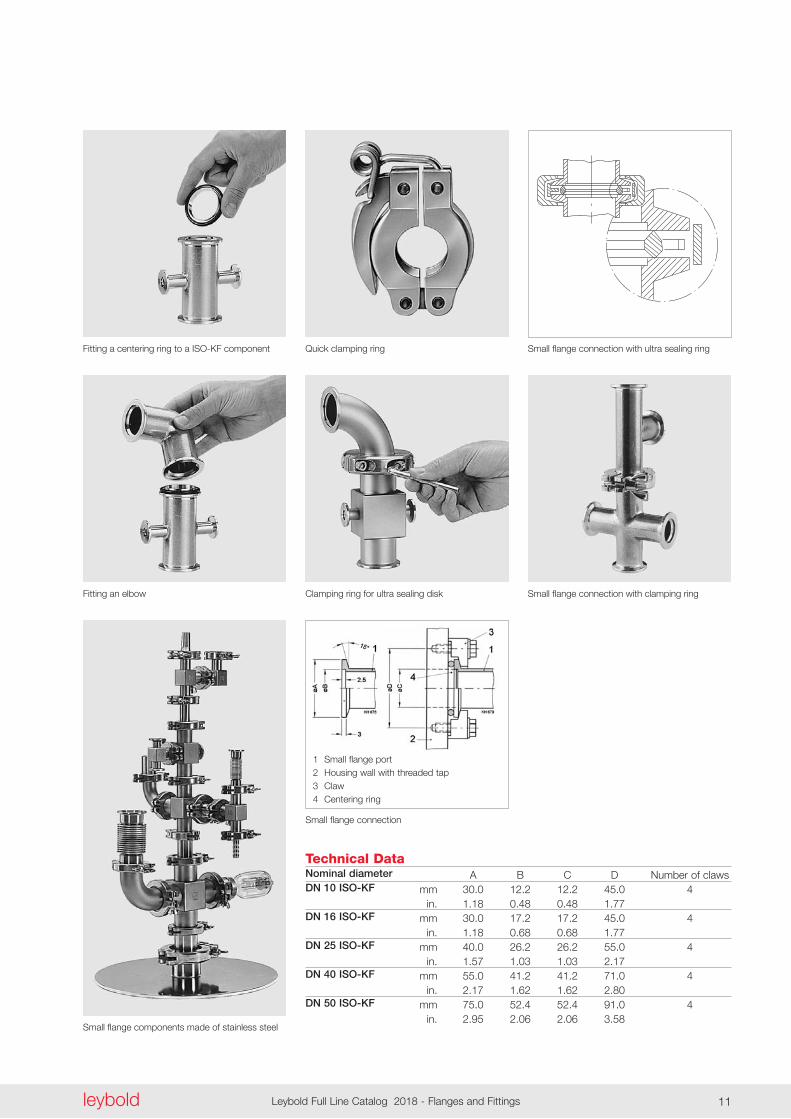
Small flange connection
1 Small flange port 2 Housing wall with threaded tap 3 Claw 4 Centering ring
Small flange components made of stainless steel
Technical DataNominal diameterDN 10 ISO-KF
DN 16 ISO-KF
DN 25 ISO-KF
DN 40 ISO-KF
DN 50 ISO-KF
A B C D Number of claws mm 30 .0 12 .2 12 .2 45 .0 4 in . 1 .18 0 .48 0 .48 1 .77 mm 30 .0 17 .2 17 .2 45 .0 4 in . 1 .18 0 .68 0 .68 1 .77 mm 40 .0 26 .2 26 .2 55 .0 4 in . 1 .57 1 .03 1 .03 2 .17 mm 55 .0 41 .2 41 .2 71 .0 4 in . 2 .17 1 .62 1 .62 2 .80 mm 75 .0 52 .4 52 .4 91 .0 4 in . 2 .95 2 .06 2 .06 3 .58
Important: In the table of Chapter “General” the German designation for the type of steel is also stated in accordance with AISI.
leyboldLeybold Full Line Catalog 2018 - Flanges and Fittings12
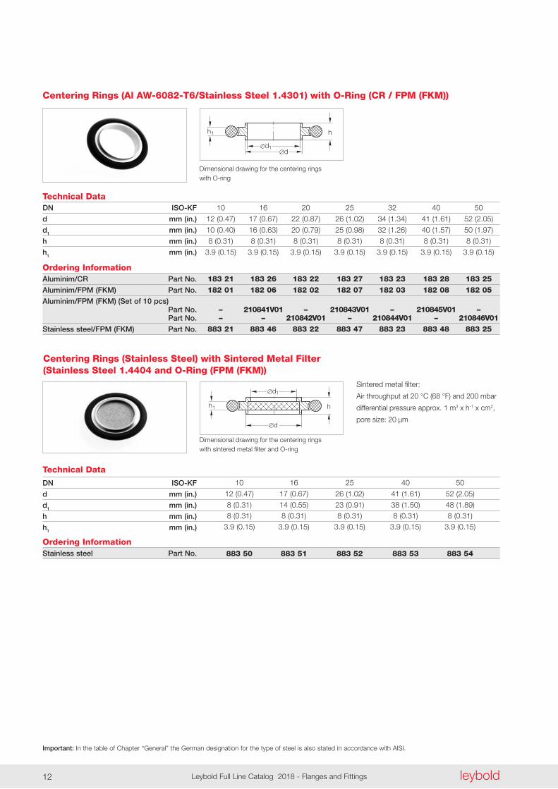
Centering Rings (Al AW-6082-T6/Stainless Steel 1.4301) with O-Ring (CR / FPM (FKM))
Technical Data 10 16 20 25 32 40 50
12 (0 .47) 17 (0 .67) 22 (0 .87) 26 (1 .02) 34 (1 .34) 41 (1 .61) 52 (2 .05)
10 (0 .40) 16 (0 .63) 20 (0 .79) 25 (0 .98) 32 (1 .26) 40 (1 .57) 50 (1 .97)
8 (0 .31) 8 (0 .31) 8 (0 .31) 8 (0 .31) 8 (0 .31) 8 (0 .31) 8 (0 .31)
3 .9 (0 .15) 3 .9 (0 .15) 3 .9 (0 .15) 3 .9 (0 .15) 3 .9 (0 .15) 3 .9 (0 .15) 3 .9 (0 .15)
183 21 183 26 183 22 183 27 183 23 183 28 183 25 182 01 182 06 182 02 182 07 182 03 182 08 182 05 – 210841V01 – 210843V01 – 210845V01 – – – 210842V01 – 210844V01 – 210846V01 883 21 883 46 883 22 883 47 883 23 883 48 883 25
DN ISO-KF
d mm (in.)
d1 mm (in.)
h mm (in.)
h1 mm (in.)
Ordering InformationAluminim/CR Part No.
Aluminim/FPM (FKM) Part No.
Aluminim/FPM (FKM) (Set of 10 pcs) Part No. Part No.
Stainless steel/FPM (FKM) Part No.
d1d
h h1
Dimensional drawing for the centering rings with O-ring
Technical Data
DN ISO-KF
d mm (in.)
d1 mm (in.)
h mm (in.)
h1 mm (in.)
Ordering InformationStainless steel Part No.
10 16 25 40 50
12 (0 .47) 17 (0 .67) 26 (1 .02) 41 (1 .61) 52 (2 .05)
8 (0 .31) 14 (0 .55) 23 (0 .91) 38 (1 .50) 48 (1 .89) 8 (0 .31) 8 (0 .31) 8 (0 .31) 8 (0 .31) 8 (0 .31) 3 .9 (0 .15) 3 .9 (0 .15) 3 .9 (0 .15) 3 .9 (0 .15) 3 .9 (0 .15)
883 50 883 51 883 52 883 53 883 54
Sintered metal filter:
Air throughput at 20 °C (68 °F) and 200 mbar
differential pressure approx . 1 m3 x h-1 x cm2,
pore size: 20 µm
Centering Rings (Stainless Steel) with Sintered Metal Filter (Stainless Steel 1.4404 and O-Ring (FPM (FKM))
d
h h
1d
1
Dimensional drawing for the centering rings with sintered metal filter and O-ring
Important: In the table of Chapter “General” the German designation for the type of steel is also stated in accordance with AISI.
leyboldLeybold Full Line Catalog 2018 - Flanges and Fittings12 leybold Leybold Full Line Catalog 2018 - Flanges and Fittings 13
Technical DataDN ISO-KF
d mm (in.)
d1 mm (in.)
d2 mm (in.)
h mm (in.)
h1 mm (in.)
Ordering InformationStainless steel Part No.
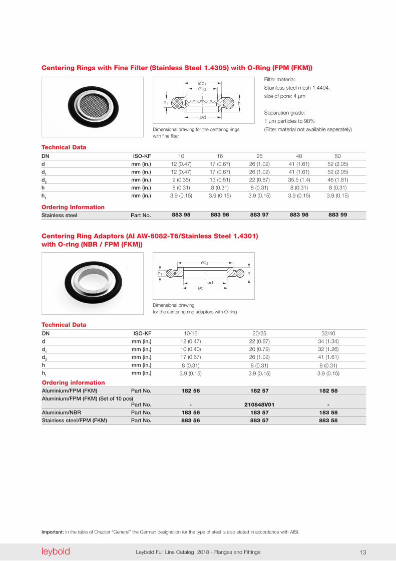
Centering Rings with Fine Filter (Stainless Steel 1.4305) with O-Ring (FPM (FKM))
10 16 25 40 50
12 (0 .47) 17 (0 .67) 26 (1 .02) 41 (1 .61) 52 (2 .05)
12 (0 .47) 17 (0 .67) 26 (1 .02) 41 (1 .61) 52 (2 .05)
9 (0 .35) 13 (0 .51) 22 (0 .87) 35 .5 (1 .4) 46 (1 .81)
8 (0 .31) 8 (0 .31) 8 (0 .31) 8 (0 .31) 8 (0 .31)
3 .9 (0 .15) 3 .9 (0 .15) 3 .9 (0 .15) 3 .9 (0 .15) 3 .9 (0 .15)
883 95 883 96 883 97 883 98 883 99
Filter material:
Stainless steel mesh 1 .4404,
size of pore: 4 µm
Separation grade:
1 µm particles to 98%
(Filter material not available seperately)
d
1d
h h
2d
1
Dimensional drawing for the centering rings with fine filter
ød1
ød2
ød
h1 h
Technical Data
Dimensional drawing for the centering ring adaptors with O-ring
DN ISO-KF
d mm (in.)
d1 mm (in.)
d2 mm (in.)
h mm (in.)
h1 mm (in.)
Ordering informationAluminium/FPM (FKM) Part No.
Aluminium/FPM (FKM) (Set of 10 pcs) Part No.
Aluminium/NBR Part No.
Stainless steel/FPM (FKM) Part No.
10/16 20/25 32/40
12 (0 .47) 22 (0 .87) 34 (1 .34)
10 (0 .40) 20 (0 .79) 32 (1 .26)
17 (0 .67) 26 (1 .02) 41 (1 .61)
8 (0 .31) 8 (0 .31) 8 (0 .31)
3 .9 (0 .15) 3 .9 (0 .15) 3 .9 (0 .15)
182 56 182 57 182 58 - 210848V01 - 183 56 183 57 183 58 883 56 883 57 883 58
Centering Ring Adaptors (Al AW-6082-T6/Stainless Steel 1.4301) with O-ring (NBR / FPM (FKM))
Important: In the table of Chapter “General” the German designation for the type of steel is also stated in accordance with AISI.
leyboldLeybold Full Line Catalog 2018 - Flanges and Fittings14
Technical Data
Dimensional drawing for the outer centering rings with O-ring
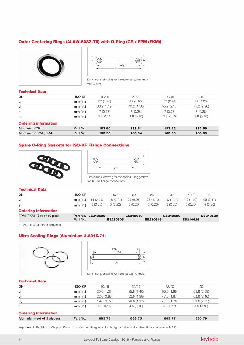
DN ISO-KF
d mm (in.)
d1 mm (in.)
h mm (in.)
h1 mm (in.)
Ordering informationAluminium/CR Part No.
Aluminium/FPM (FKM) Part No.
10/16 20/25 32/40 50 32 (1 .26) 42 (1 .65) 57 (2 .24) 77 (3 .03)
30 .2 (1 .19) 40 .2 (1 .58) 55 .2 (2 .17) 75 .2 (2 .96)
7 (0 .28) 7 (0 .28) 7 (0 .28) 7 (0 .28)
3 .9 (0 .15) 3 .9 (0 .15) 3 .9 (0 .15) 3 .9 (0 .15)
183 50 183 51 183 52 183 59 183 53 183 54 183 55 183 60
Outer Centering Rings (Al AW-6082-T6) with O-Ring (CR / FPM (FKM))
07.00.M.021-E (Außen-Zentrier)
ød1ød
h1 h
d
s
Technical Data
Dimensional drawing for the spare O-ring gaskets for ISO-KF flange connections
DN ISO-KF
d mm (in.)
s mm (in.)
Ordering InformationFPM (FKM) (Set of 10 pcs) Part No. Part No.1) Also for adaptor/centering rings
10 16 1) 20 25 1) 32 40 1) 50
15 (0 .59) 18 (0 .71) 25 (0 .98) 28 (1 .10) 40 (1 .57) 42 (1 .65) 55 (2 .17)
5 (0 .20) 5 (0 .20) 5 (0 .20) 5 (0 .20) 5 (0 .20) 5 (0 .20) 5 (0 .20)
ES210600 – ES210610 – ES210620 – ES210630 – ES210605 – ES210615 – ES210625 –
Spare O-Ring Gaskets for ISO-KF Flange Connections
Technical Data
Dimensional drawing for the ultra sealing rings
DN ISO-KF
d mm (in.)
d1 mm (in.)
d2 mm (in.)
h mm (in.)
Ordering InformationAluminium (set of 3 pieces) Part No.
Ultra Sealing Rings (Aluminium 3.2315.71)
10/16 20/25 32/40 50
25 .6 (1 .01) 35 .6 (1 .40) 50 .6 (1 .99) 65 .6 (2 .58)
22 .6 (0 .89) 32 .6 (1 .38) 47 .6 (1 .87) 62 .6 (2 .46)
19 .6 (0 .77) 29 .6 (1 .17) 44 .6 (1 .76) 59 .6 (2 .35) 4 .5 (0 .18) 4 .5 (0 .18) 4 .5 (0 .18) 4 .5 (0 .18)
883 73 883 75 883 77 883 79
h
1d
d
d2
Important: In the table of Chapter “General” the German designation for the type of steel is also stated in accordance with AISI.
leyboldLeybold Full Line Catalog 2018 - Flanges and Fittings14 leybold Leybold Full Line Catalog 2018 - Flanges and Fittings 15
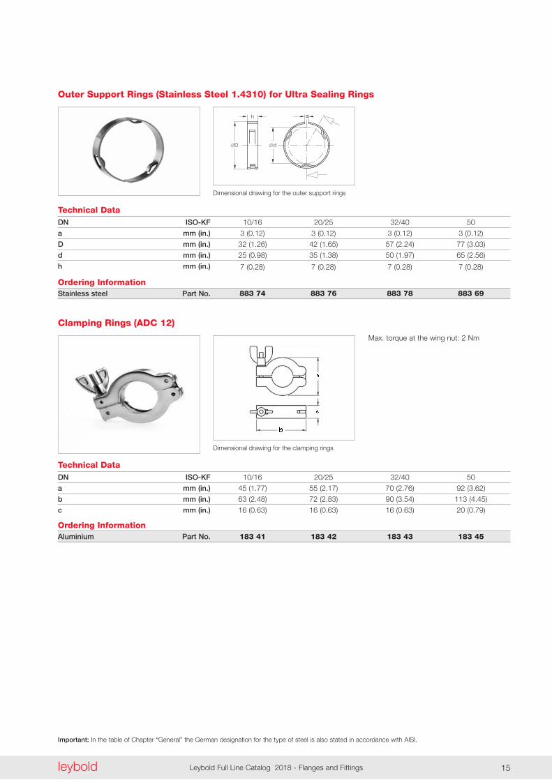
Technical DataDN ISO-KF
a mm (in.)
D mm (in.)
d mm (in.)
h mm (in.)
Ordering InformationStainless steel Part No.
Outer Support Rings (Stainless Steel 1.4310) for Ultra Sealing Rings
10/16 20/25 32/40 50
3 (0 .12) 3 (0 .12) 3 (0 .12) 3 (0 .12)
32 (1 .26) 42 (1 .65) 57 (2 .24) 77 (3 .03)
25 (0 .98) 35 (1 .38) 50 (1 .97) 65 (2 .56)
7 (0 .28) 7 (0 .28) 7 (0 .28) 7 (0 .28)
883 74 883 76 883 78 883 69
dD
h a
Dimensional drawing for the outer support rings
Technical Data
Dimensional drawing for the clamping rings
DN ISO-KF
a mm (in.)
b mm (in.)
c mm (in.)
Ordering InformationAluminium Part No.
Clamping Rings (ADC 12)
10/16 20/25 32/40 50
45 (1 .77) 55 (2 .17) 70 (2 .76) 92 (3 .62)
63 (2 .48) 72 (2 .83) 90 (3 .54) 113 (4 .45)
16 (0 .63) 16 (0 .63) 16 (0 .63) 20 (0 .79)
183 41 183 42 183 43 183 45
Max . torque at the wing nut: 2 Nm
Important: In the table of Chapter “General” the German designation for the type of steel is also stated in accordance with AISI.
leyboldLeybold Full Line Catalog 2018 - Flanges and Fittings16
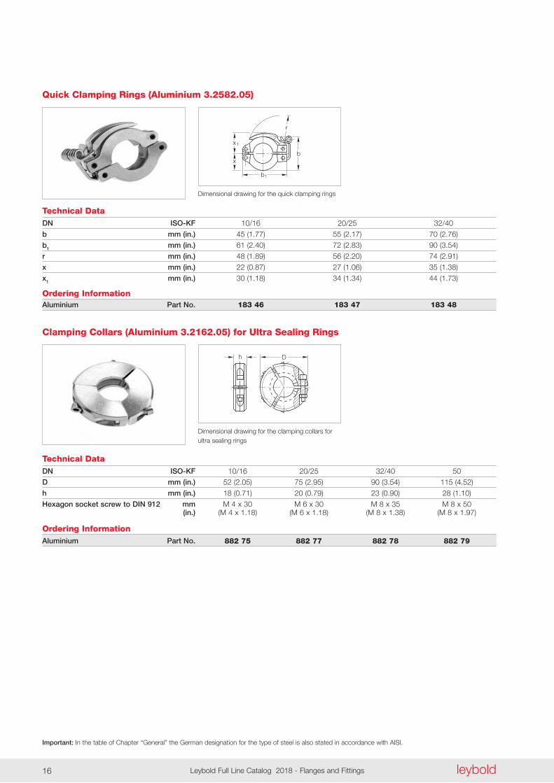
Quick Clamping Rings (Aluminium 3.2582.05)
x1
x
b1
b
r
Technical Data
Dimensional drawing for the quick clamping rings
DN ISO-KF
b mm (in.)
b1 mm (in.)
r mm (in.)
x mm (in.)
x1 mm (in.)
Ordering InformationAluminium Part No.
10/16 20/25 32/40
45 (1 .77) 55 (2 .17) 70 (2 .76)
61 (2 .40) 72 (2 .83) 90 (3 .54)
48 (1 .89) 56 (2 .20) 74 (2 .91)
22 (0 .87) 27 (1 .06) 35 (1 .38)
30 (1 .18) 34 (1 .34) 44 (1 .73)
183 46 183 47 183 48
Dh
Technical Data
Dimensional drawing for the clamping collars for ultra sealing rings
DN ISO-KF
D mm (in.)
h mm (in.)
Hexagon socket screw to DIN 912 mm (in.)
Ordering InformationAluminium Part No.
Clamping Collars (Aluminium 3.2162.05) for Ultra Sealing Rings
10/16 20/25 32/40 50
52 (2 .05) 75 (2 .95) 90 (3 .54) 115 (4 .52)
18 (0 .71) 20 (0 .79) 23 (0 .90) 28 (1 .10)
M 4 x 30 M 6 x 30 M 8 x 35 M 8 x 50 (M 4 x 1 .18) (M 6 x 1 .18) (M 8 x 1 .38) (M 8 x 1 .97)
882 75 882 77 882 78 882 79
Important: In the table of Chapter “General” the German designation for the type of steel is also stated in accordance with AISI.
leyboldLeybold Full Line Catalog 2018 - Flanges and Fittings16 leybold Leybold Full Line Catalog 2018 - Flanges and Fittings 17
Technical DataDN ISO-KF
a mm (in.)
a1 mm (in.)
b mm (in.)
h mm (in.)
h1 mm (in.)
h2 mm (in.)
Ordering InformationAluminium (Set of 4 pieces) Part No.
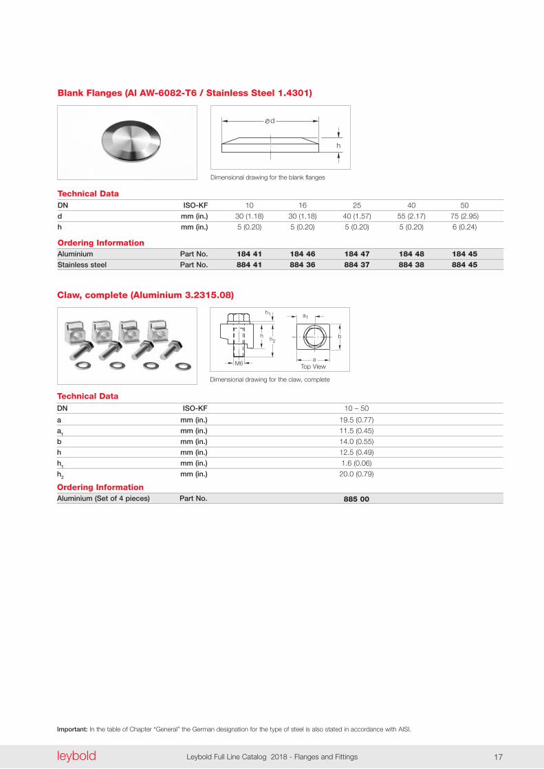
Claw, complete (Aluminium 3.2315.08)
10 – 50
19 .5 (0 .77)
11 .5 (0 .45)
14 .0 (0 .55)
12 .5 (0 .49)
1 .6 (0 .06)
20 .0 (0 .79)
885 00
M6
h
h1
a
h2
a1
b
Dimensional drawing for the claw, complete
Top View
d
h
Technical Data
Dimensional drawing for the blank flanges
DN ISO-KF
d mm (in.)
h mm (in.)
Ordering InformationAluminium Part No.
Stainless steel Part No.
Blank Flanges (Al AW-6082-T6 / Stainless Steel 1.4301)
10 16 25 40 50
30 (1 .18) 30 (1 .18) 40 (1 .57) 55 (2 .17) 75 (2 .95)
5 (0 .20) 5 (0 .20) 5 (0 .20) 5 (0 .20) 6 (0 .24)
184 41 184 46 184 47 184 48 184 45 884 41 884 36 884 37 884 38 884 45
Important: In the table of Chapter “General” the German designation for the type of steel is also stated in accordance with AISI.
leyboldLeybold Full Line Catalog 2018 - Flanges and Fittings18
2ød
DN
l
1ød
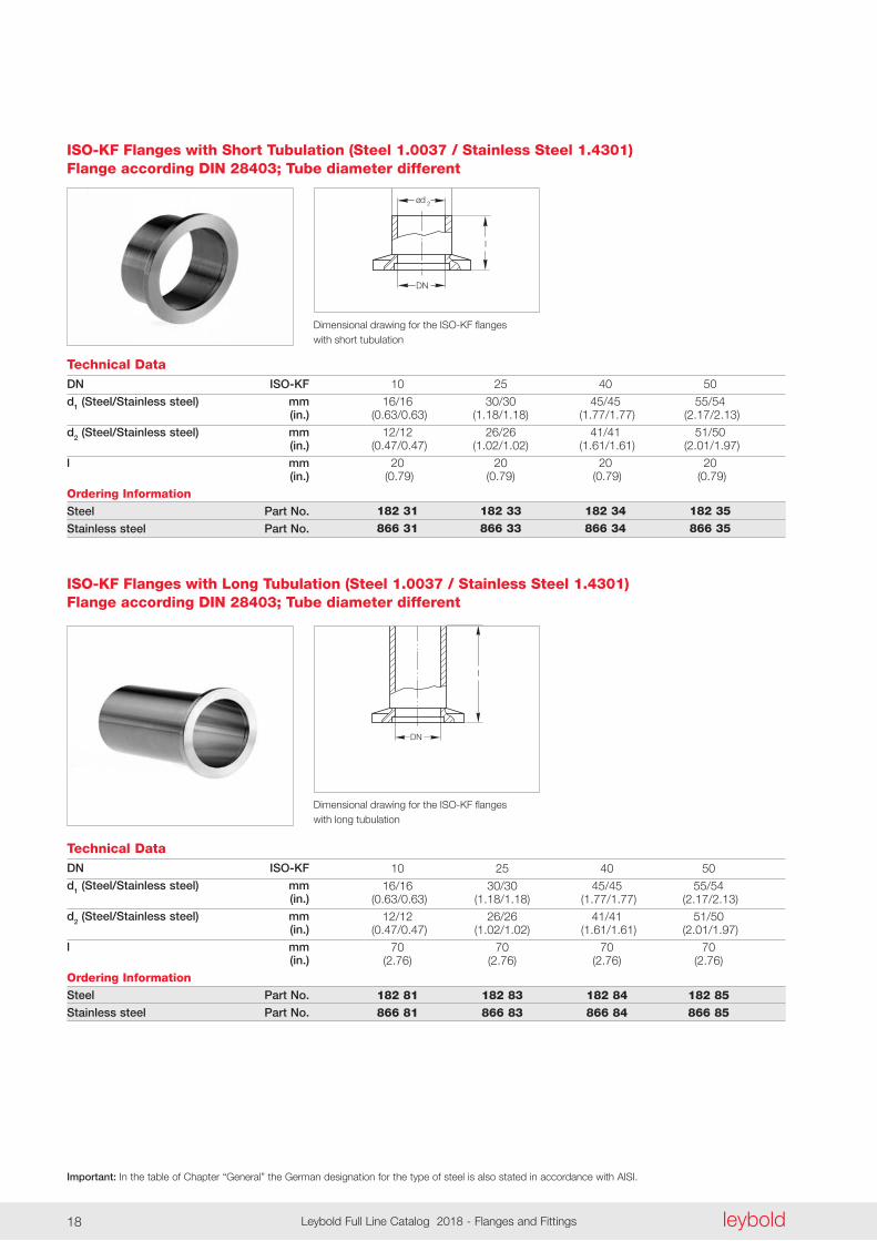
Dimensional drawing for the ISO-KF flanges with short tubulation
ISO-KF Flanges with Short Tubulation (Steel 1.0037 / Stainless Steel 1.4301) Flange according DIN 28403; Tube diameter different
Technical DataDN ISO-KF
d1 (Steel/Stainless steel) mm (in.)
d2 (Steel/Stainless steel) mm (in.)
l mm (in.)
Ordering InformationSteel Part No.
Stainless steel Part No.
10 25 40 50
16/16 30/30 45/45 55/54 (0 .63/0 .63) (1 .18/1 .18) (1 .77/1 .77) (2 .17/2 .13)
12/12 26/26 41/41 51/50 (0 .47/0 .47) (1 .02/1 .02) (1 .61/1 .61) (2 .01/1 .97)
20 20 20 20 (0 .79) (0 .79) (0 .79) (0 .79)
182 31 182 33 182 34 182 35
866 31 866 33 866 34 866 35
DN
l
2ød
1ød
Technical Data
Dimensional drawing for the ISO-KF flanges with long tubulation
DN ISO-KF
d1 (Steel/Stainless steel) mm (in.)
d2 (Steel/Stainless steel) mm (in.)
l mm (in.)
Ordering InformationSteel Part No.
Stainless steel Part No.
ISO-KF Flanges with Long Tubulation (Steel 1.0037 / Stainless Steel 1.4301) Flange according DIN 28403; Tube diameter different
10 25 40 50
16/16 30/30 45/45 55/54 (0 .63/0 .63) (1 .18/1 .18) (1 .77/1 .77) (2 .17/2 .13)
12/12 26/26 41/41 51/50 (0 .47/0 .47) (1 .02/1 .02) (1 .61/1 .61) (2 .01/1 .97)
70 70 70 70 (2 .76) (2 .76) (2 .76) (2 .76)
182 81 182 83 182 84 182 85 866 81 866 83 866 84 866 85
Important: In the table of Chapter “General” the German designation for the type of steel is also stated in accordance with AISI.
leyboldLeybold Full Line Catalog 2018 - Flanges and Fittings18 leybold Leybold Full Line Catalog 2018 - Flanges and Fittings 19
2ød
DN
l
1ød
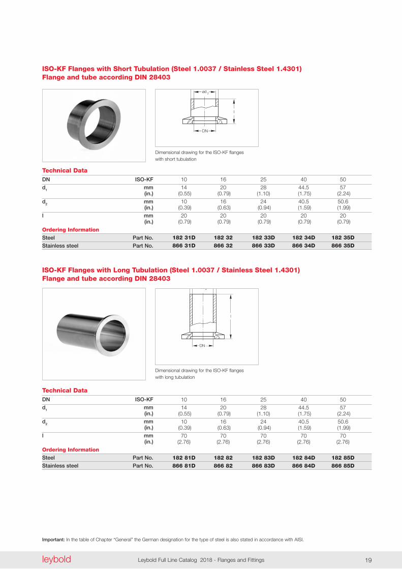
Dimensional drawing for the ISO-KF flanges with short tubulation
ISO-KF Flanges with Short Tubulation (Steel 1.0037 / Stainless Steel 1.4301) Flange and tube according DIN 28403
Technical DataDN ISO-KF
d1 mm (in.)
d2 mm (in.)
l mm (in.)
Ordering InformationSteel Part No.
Stainless steel Part No.
10 16 25 40 50
14 20 28 44 .5 57 (0 .55) (0 .79) (1 .10) (1 .75) (2 .24)
10 16 24 40 .5 50 .6 (0 .39) (0 .63) (0 .94) (1 .59) (1 .99)
20 20 20 20 20 (0 .79) (0 .79) (0 .79) (0 .79) (0 .79)
182 31D 182 32 182 33D 182 34D 182 35D
866 31D 866 32 866 33D 866 34D 866 35D
DN
l
2ød
1ød
Technical Data
Dimensional drawing for the ISO-KF flanges with long tubulation
DN ISO-KF
d1 mm (in.)
d2 mm (in.)
l mm (in.)
Ordering InformationSteel Part No.
Stainless steel Part No.
ISO-KF Flanges with Long Tubulation (Steel 1.0037 / Stainless Steel 1.4301) Flange and tube according DIN 28403
10 16 25 40 50
14 20 28 44 .5 57 (0 .55) (0 .79) (1 .10) (1 .75) (2 .24)
10 16 24 40 .5 50 .6 (0 .39) (0 .63) (0 .94) (1 .59) (1 .99)
70 70 70 70 70 (2 .76) (2 .76) (2 .76) (2 .76) (2 .76)
182 81D 182 82 182 83D 182 84D 182 85D 866 81D 866 82 866 83D 866 84D 866 85D
Important: In the table of Chapter “General” the German designation for the type of steel is also stated in accordance with AISI.
leyboldLeybold Full Line Catalog 2018 - Flanges and Fittings20
DN DN
l
Technical Data
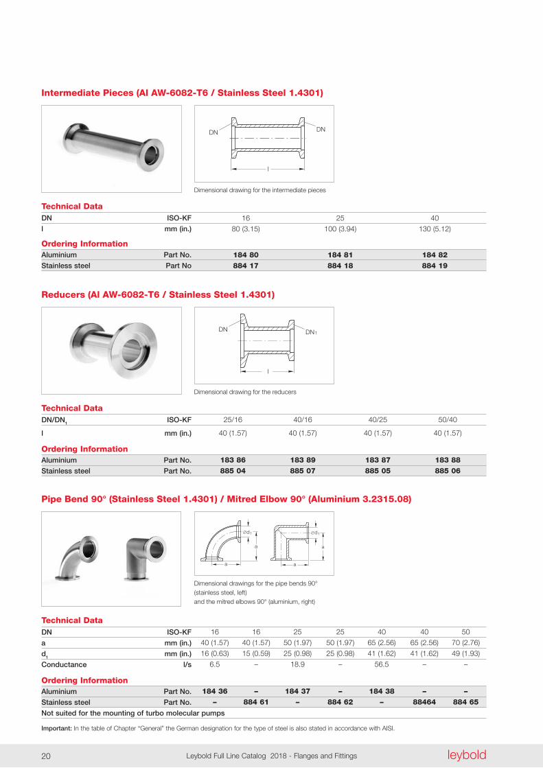
Dimensional drawing for the intermediate pieces
DN ISO-KF
l mm (in.)
Ordering InformationAluminium Part No.
Stainless steel Part No
Intermediate Pieces (Al AW-6082-T6 / Stainless Steel 1.4301)
16 25 40
80 (3 .15) 100 (3 .94) 130 (5 .12)
184 80 184 81 184 82 884 17 884 18 884 19
Technical Data
Dimensional drawing for the reducers
DN/DN1 ISO-KF
l mm (in.)
Ordering InformationAluminium Part No.
Stainless steel Part No.
Reducers (Al AW-6082-T6 / Stainless Steel 1.4301)
25/16 40/16 40/25 50/40
40 (1 .57) 40 (1 .57) 40 (1 .57) 40 (1 .57)
183 86 183 89 183 87 183 88 885 04 885 07 885 05 885 06
1
l
DN DN
a
a
d1 d1
a
a
DN ISO-KF
a mm (in.)
d1 mm (in.)
Conductance l/s
Ordering InformationAluminium Part No.
Stainless steel Part No.
Not suited for the mounting of turbo molecular pumps
Technical Data
Dimensional drawings for the pipe bends 90° (stainless steel, left) and the mitred elbows 90° (aluminium, right)
Pipe Bend 90° (Stainless Steel 1.4301) / Mitred Elbow 90° (Aluminium 3.2315.08)
16 16 25 25 40 40 50
40 (1 .57) 40 (1 .57) 50 (1 .97) 50 (1 .97) 65 (2 .56) 65 (2 .56) 70 (2 .76)
16 (0 .63) 15 (0 .59) 25 (0 .98) 25 (0 .98) 41 (1 .62) 41 (1 .62) 49 (1 .93)
6 .5 – 18 .9 – 56 .5 – –
184 36 – 184 37 – 184 38 – – – 884 61 – 884 62 – 88464 884 65
Important: In the table of Chapter “General” the German designation for the type of steel is also stated in accordance with AISI.
leyboldLeybold Full Line Catalog 2018 - Flanges and Fittings20 leybold Leybold Full Line Catalog 2018 - Flanges and Fittings 21
d
a
ab
1
DN ISO-KF
a mm (in.)
b mm (in.)
d1 (aluminium) mm (in.)
d1 (stainless steel) mm (in.)
Conductance l/s
Ordering InformationAluminium Part No.
Stainless steel Part No.
Not suited for the mounting of turbo molecular pumps
Technical Data
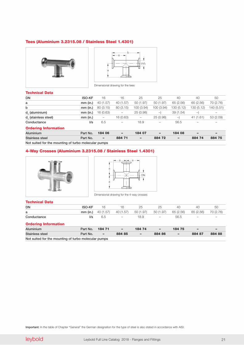
Dimensional drawing for the tees
Tees (Aluminium 3.2315.08 / Stainless Steel 1.4301)
16 16 25 25 40 40 50
40 (1 .57) 40 (1 .57) 50 (1 .97) 50 (1 .97) 65 (2 .56) 65 (2 .56) 70 (2 .76)
80 (3 .15) 80 (3 .15) 100 (3 .94) 100 (3 .94) 130 (5 .12) 130 (5 .12) 140 (5 .51)
16 (0 .63) – 25 (0 .98) –) 39 (1 .54) –) –
– 16 (0 .63) – 25 (0 .98) –) 41 (1 .61) 53 (2 .09)
6 .5 – 18 .9 – 56 .5 – –
184 06 – 184 07 – 184 08 – – – 884 71 – 884 72 – 884 74 884 75
DN
aa
a
a
DN ISO-KF
a mm (in.)
Conductance l/s
Ordering InformationAluminium Part No.
Stainless steel Part No.
Not suited for the mounting of turbo molecular pumps
Technical Data
Dimensional drawing for the 4-way crosses
4-Way Crosses (Aluminium 3.2315.08 / Stainless Steel 1.4301)
16 16 25 25 40 40 50
40 (1 .57) 40 (1 .57) 50 (1 .97) 50 (1 .97) 65 (2 .56) 65 (2 .56) 70 (2 .76)
6 .5 – 18 .9 – 56 .5 – –
184 71 – 184 74 – 184 75 – – – 884 85 – 884 86 – 884 87 884 88
Important: In the table of Chapter “General” the German designation for the type of steel is also stated in accordance with AISI.
leyboldLeybold Full Line Catalog 2018 - Flanges and Fittings22
a
DN
a
1a
1a
1
DN
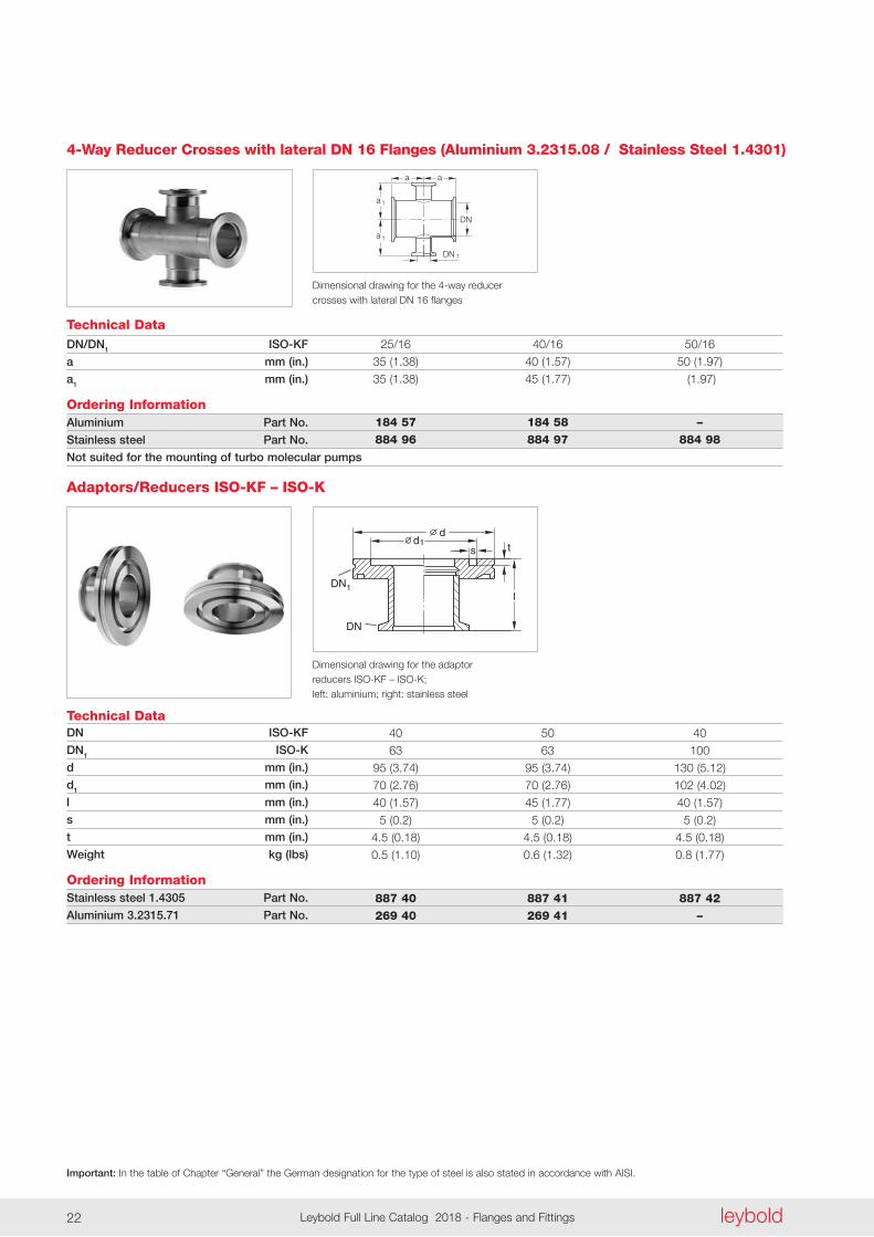
Technical Data
Dimensional drawing for the 4-way reducer crosses with lateral DN 16 flanges
DN/DN1 ISO-KF
a mm (in.)
a1 mm (in.)
Ordering InformationAluminium Part No.
Stainless steel Part No.
Not suited for the mounting of turbo molecular pumps
4-Way Reducer Crosses with lateral DN 16 Flanges (Aluminium 3.2315.08 / Stainless Steel 1.4301)
25/16 40/16 50/16
35 (1 .38) 40 (1 .57) 50 (1 .97)
35 (1 .38) 45 (1 .77) (1 .97)
184 57 184 58 – 884 96 884 97 884 98
l
d1s t
d
DN
DN1
Technical Data
Dimensional drawing for the adaptor reducers ISO-KF – ISO-K; left: aluminium; right: stainless steel
DN ISO-KF
DN1 ISO-K
d mm (in.)
d1 mm (in.)
l mm (in.)
s mm (in.)
t mm (in.)
Weight kg (lbs)
Ordering InformationStainless steel 1.4305 Part No.
Aluminium 3.2315.71 Part No.
Adaptors/Reducers ISO-KF – ISO-K
40 50 40
63 63 100
95 (3 .74) 95 (3 .74) 130 (5 .12)
70 (2 .76) 70 (2 .76) 102 (4 .02)
40 (1 .57) 45 (1 .77) 40 (1 .57)
5 (0 .2) 5 (0 .2) 5 (0 .2)
4 .5 (0 .18) 4 .5 (0 .18) 4 .5 (0 .18)
0 .5 (1 .10) 0 .6 (1 .32) 0 .8 (1 .77)
887 40 887 41 887 42 269 40 269 41 –
Important: In the table of Chapter “General” the German designation for the type of steel is also stated in accordance with AISI.
leyboldLeybold Full Line Catalog 2018 - Flanges and Fittings22 leybold Leybold Full Line Catalog 2018 - Flanges and Fittings 23
DN
hd1
dd
DN1
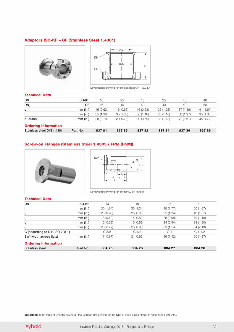
Technical Data
Dimensional drawing for the adaptors CF – ISO-KF
DN ISO-KF
DN1 CF
d mm (in.)
h mm (in.)
d1 (tube) mm (in.)
Ordering InformationStainless steel DIN 1.4301 Part No.
Adaptors ISO-KF – CF (Stainless Steel 1.4301)
16 25 16 25 40 40
16 16 40 40 40 63
16 (0 .63) 16 (0 .63) 16 (0 .63) 26 (1 .02) 37 (1 .36) 41 (1 .61)
35 (1 .38) 35 (1 .38) 30 (1 .18) 30 (1 .18) 50 (1 .97) 35 (1 .38)
20 (0 .79) 20 (0 .79) 20 (0 .79) 30 (1 .18) 41 (1 .61) 45 (1 .77)
837 81 837 83 837 82 837 84 837 36 837 86
SWd G
l1l2
l
1d
Technical Data
Dimensional drawing for the screw-on flanges
DN ISO-KF
l mm (in.)
l1 mm (in.)
l2 mm (in.)
d mm (in.)
d1 mm (in.)
G (according to DIN ISO 228-1)
SW (width across flats) mm (in.)
Ordering InformationStainless steel Part No.
Screw-on Flanges (Stainless Steel 1.4305 / FPM (FKM))
10 16 25 40
35 (1 .34) 35 (1 .34) 45 (1 .77) 50 (1 .97)
25 (0 .98) 25 (0 .98) 35 (1 .34) 40 (1 .57)
15 (0 .59) 15 (0 .59) 25 (0 .98) 30 (1 .18)
10 (0 .39) 15 (0 .59) 24 (0 .94) 38 (1 .50)
20 (0 .79) 25 (0 .98) 39 (1 .54) 54 (2 .13)
G 3/8 G 1/2 G 1 G 1 1/2
17 (0 .67) 21 (0 .83) 36 (1 .42) 50 (1 .97)
884 25 884 26 884 27 884 28
Important: In the table of Chapter “General” the German designation for the type of steel is also stated in accordance with AISI.
leyboldLeybold Full Line Catalog 2018 - Flanges and Fittings24
dG
SW
l1l2
l
1d
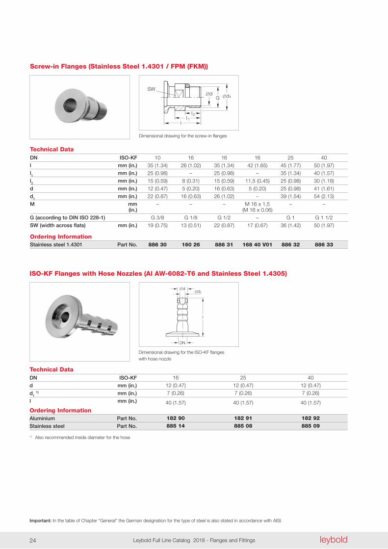
Technical Data
Dimensional drawing for the screw-in flanges
DN ISO-KF
l mm (in.)
l1 mm (in.)
l2 mm (in.)
d mm (in.)
d1 mm (in.)
M mm (in.)
G (according to DIN ISO 228-1)
SW (width across flats) mm (in.)
Ordering InformationStainless steel 1.4301 Part No.
Screw-in Flanges (Stainless Steel 1.4301 / FPM (FKM))
10 16 16 16 25 40
35 (1 .34) 26 (1 .02) 35 (1 .34) 42 (1 .65) 45 (1 .77) 50 (1 .97)
25 (0 .98) – 25 (0 .98) – 35 (1 .34) 40 (1 .57)
15 (0 .59) 8 (0 .31) 15 (0 .59) 11,5 (0 .45) 25 (0 .98) 30 (1 .18)
12 (0 .47) 5 (0 .20) 16 (0 .63) 5 (0 .20) 25 (0 .98) 41 (1 .61)
22 (0 .87) 16 (0 .63) 26 (1 .02) – 39 (1 .54) 54 (2 .13)
– – – M 16 x 1,5 – – (M 16 x 0 .06)
G 3/8 G 1/8 G 1/2 – G 1 G 1 1/2
19 (0 .75) 13 (0 .51) 22 (0 .87) 17 (0 .67) 36 (1 .42) 50 (1 .97)
886 30 160 26 886 31 168 40 V01 886 32 886 33
Technical Data
Dimensional drawing for the ISO-KF flanges with hose nozzle
DN ISO-KF
d mm (in.)
d1 1) mm (in.)
l mm (in.)
Ordering InformationAluminium Part No.
Stainless steel Part No.
1) Also recommended inside diameter for the hose
ISO-KF Flanges with Hose Nozzles (Al AW-6082-T6 and Stainless Steel 1.4305)
16 25 40
12 (0 .47) 12 (0 .47) 12 (0 .47)
7 (0 .26) 7 (0 .26) 7 (0 .26)
40 (1 .57) 40 (1 .57) 40 (1 .57)
182 90 182 91 182 92 885 14 885 08 885 09
d
DN
1
l
d
Important: In the table of Chapter “General” the German designation for the type of steel is also stated in accordance with AISI.
leyboldLeybold Full Line Catalog 2018 - Flanges and Fittings24 leybold Leybold Full Line Catalog 2018 - Flanges and Fittings 25
1 dd
Technical Data
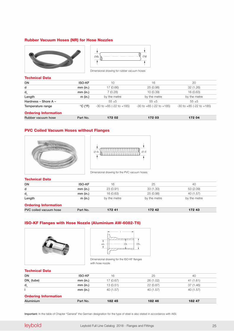
Dimensional drawing for rubber vacuum hoses
DN ISO-KF
d mm (in.)
d1 mm (in.)
Length m (in.)
Hardness – Shore A –
Temperature range °C (°F)
Ordering InformationRubber vacuum hose Part No.
Rubber Vacuum Hoses (NR) for Hose Nozzles
10 16 20
17 (0 .66) 25 (0 .98) 32 (1 .26)
7 (0 .28) 10 (0 .39) 16 (0 .63)
by the metre by the metre by the metre
55 ±5 55 ±5 55 ±5
-30 to +85 (-22 to +185) -30 to +85 (-22 to +185) -30 to +85 (-22 to +185)
172 02 172 03 172 04
d1d
Technical Data
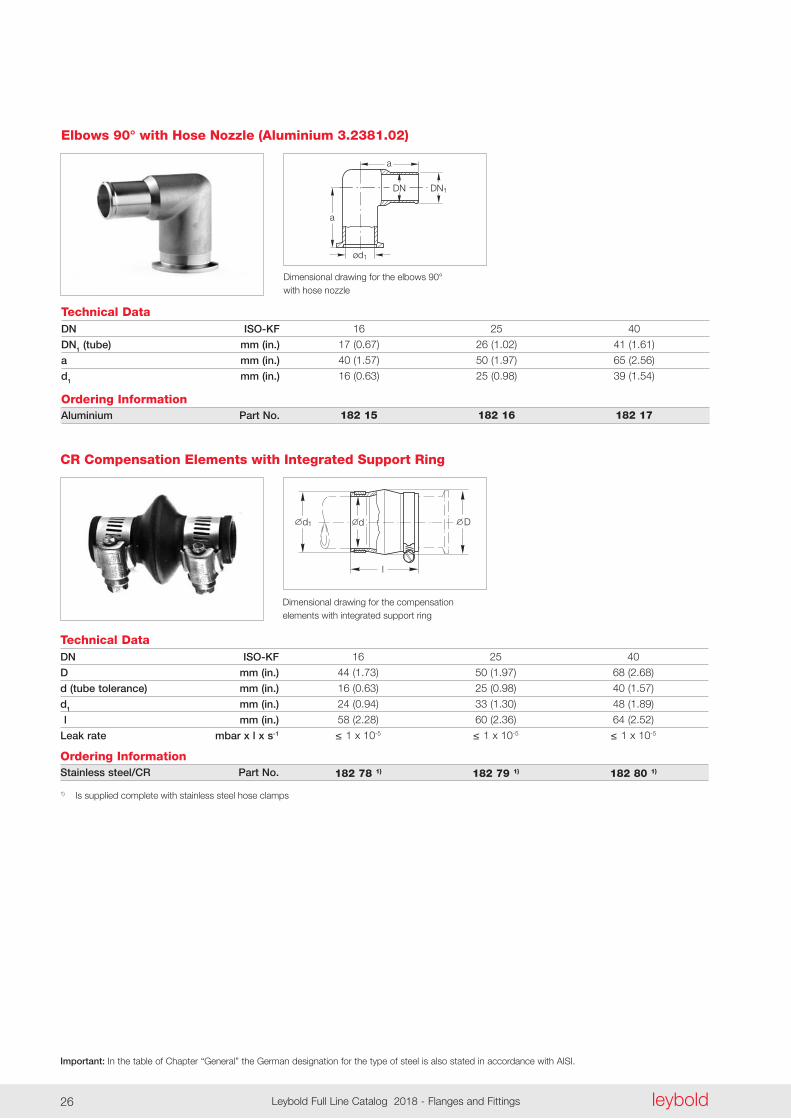
Dimensional drawing for the PVC vacuum hoses
DN ISO-KF
d mm (in.)
d1 mm (in.)
Length m (in.)
Ordering InformationPVC coiled vacuum hose Part No.
PVC Coiled Vacuum Hoses without Flanges
16 25 40
23 (0 .91) 33 (1 .30) 53 (2 .09)
16 (0 .63) 25 (0 .98) 40 (1 .57)
by the metre by the metre by the metre
172 41 172 42 172 43
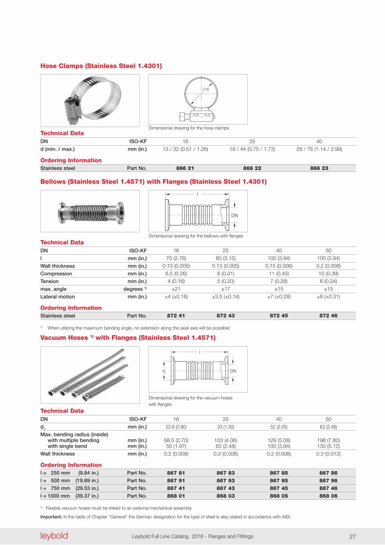
Technical DataDN ISO-KF
DN1 (tube) mm (in.)
d1 mm (in.)
l mm (in.)
Ordering InformationAluminium Part No.
ISO-KF Flanges with Hose Nozzle (Aluminium AW-6082-T6)
16 25 40
17 (0 .67) 26 (1 .02) 41 (1 .61)
13 (0 .51) 22 (0 .87) 37 (1 .46) 40 (1 .57) 40 (1 .57) 40 (1 .57)
182 45 182 46 182 47
DN1ød1 DN
l
Dimensional drawing for the ISO-KF flanges with hose nozzle
Important: In the table of Chapter “General” the German designation for the type of steel is also stated in accordance with AISI.
leyboldLeybold Full Line Catalog 2018 - Flanges and Fittings26
a
a
ød1
DN1DN
Technical Data
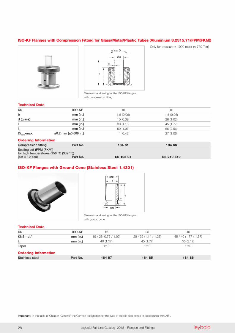
Dimensional drawing for the elbows 90° with hose nozzle
DN ISO-KF
DN1 (tube) mm (in.)
a mm (in.)
d1 mm (in.)
Ordering InformationAluminium Part No.
Elbows 90° with Hose Nozzle (Aluminium 3.2381.02)
16 25 40
17 (0 .67) 26 (1 .02) 41 (1 .61)
40 (1 .57) 50 (1 .97) 65 (2 .56)
16 (0 .63) 25 (0 .98) 39 (1 .54)
182 15 182 16 182 17
l
Ddd1
Technical Data
Dimensional drawing for the compensation elements with integrated support ring
DN ISO-KF
D mm (in.)
d (tube tolerance) mm (in.)
d1 mm (in.)
l mm (in.)
Leak rate mbar x l x s-1
Ordering InformationStainless steel/CR Part No.
1) Is supplied complete with stainless steel hose clamps
CR Compensation Elements with Integrated Support Ring
16 25 40
44 (1 .73) 50 (1 .97) 68 (2 .68)
16 (0 .63) 25 (0 .98) 40 (1 .57)
24 (0 .94) 33 (1 .30) 48 (1 .89)
58 (2 .28) 60 (2 .36) 64 (2 .52)
≤ 1 x 10⁻⁵ ≤ 1 x 10⁻⁵ ≤ 1 x 10⁻⁵
182 78 1) 182 79 1) 182 80 1)
Important: In the table of Chapter “General” the German designation for the type of steel is also stated in accordance with AISI.
leyboldLeybold Full Line Catalog 2018 - Flanges and Fittings26 leybold Leybold Full Line Catalog 2018 - Flanges and Fittings 27
d
Technical DataDimensional drawing for the hose clamps
DN ISO-KF
d (min. / max.) mm (in.)
Ordering InformationStainless steel Part No.
Hose Clamps (Stainless Steel 1.4301)
16 25 40
13 / 32 (0 .51 / 1 .26) 19 / 44 (0 .75 / 1 .73) 29 / 76 (1 .14 / 2 .99)
866 21 866 22 866 23
DN
l
Technical DataDimensional drawing for the bellows with flanges
DN ISO-KF
l mm (in.)
Wall thickness mm (in.)
Compression mm (in.)
Tension mm (in.)
max. angle degrees 1)
Lateral motion mm (in.)
Ordering InformationStainless steel Part No.
1) When utilizing the maximum bending angle, no extension along the axial axis will be possible!
Bellows (Stainless Steel 1.4571) with Flanges (Stainless Steel 1.4301)
16 25 40 50
70 (2 .76) 80 (3 .15) 100 (3 .94) 100 (3 .94)
0 .13 (0 .005) 0 .13 (0 .005) 0,15 (0 .006) 0,2 (0 .008)
6 .5 (0 .26) 8 (0 .31) 11 (0 .43) 10 (0 .39)
4 (0 .16) 5 (0 .20) 7 (0 .28) 6 (0 .24)
±21 ±17 ±15 ±15
±4 (±0 .16) ±3,5 (±0 .14) ±7 (±0 .28) ±8 (±0 .31)
872 41 872 43 872 45 872 46
DN
l
d1
Technical Data
Dimensional drawing for the vacuum hoses with flanges
DN ISO-KF
d1 mm (in.)
Max. bending radius (inside) with multiple bending mm (in.) with single bend mm (in.)
Wall thickness mm (in.)
Ordering Informationl = 250 mm (9.84 in.) Part No.
l = 500 mm (19.69 in.) Part No.
l = 750 mm (29.53 in.) Part No.
l = 1000 mm (39.37 in.) Part No.
1) Flexible vacuum hoses must be linked to an external mechanical assembly
Vacuum Hoses 1) with Flanges (Stainless Steel 1.4571)
16 25 40 50
22 .8 (0 .90) 33 (1 .30) 52 (2 .05) 63 (2 .48)
68 .5 (2 .70) 103 (4 .06) 129 (5 .08) 198 (7 .80) 50 (1 .97) 63 (2 .48) 100 (3 .94) 130 (5 .12)
0 .2 (0 .008) 0 .2 (0 .008) 0 .2 (0 .008) 0 .3 (0 .012)
867 81 867 83 867 85 867 86 867 91 867 93 867 95 867 96 867 41 867 43 867 45 867 46 868 01 868 03 868 05 868 06
Important: In the table of Chapter “General” the German designation for the type of steel is also stated in accordance with AISI.
leyboldLeybold Full Line Catalog 2018 - Flanges and Fittings28
Technical Data
Dimensional drawing for the ISO-KF flanges with ground cone
DN ISO-KF
KNS - d / l mm (in.)
l1 mm (in.)
Taper
Ordering InformationStainless steel Part No.
ISO-KF Flanges with Ground Cone (Stainless Steel 1.4301)
16 25 40
19 / 26 (0 .75 / 1 .02) 29 / 32 (1 .14 / 1 .26) 45 / 40 (1 .77 / 1 .57)
40 (1 .57) 45 (1 .77) 55 (2 .17)
1:10 1:10 1:10
184 87 184 85 184 86
Technical Data
Dimensional drawing for the ISO-KF flanges with compression fitting
DN ISO-KF
b mm (in.)
d (glass) mm (in.)
l mm (in.)
l1 mm (in.)
Dibore-max. ±0.2 mm (±0.008 in.)
Ordering InformationCompression fitting Part No.
Sealing set (FPM (FKM)) for high temperatures (150 °C (302 °F)) (set = 10 pcs) Part No.
ISO-KF Flanges with Compression Fitting for Glass/Metal/Plastic Tubes (Aluminium 3.2315.71/FPM(FKM))
10 40
1 .5 (0 .06) 1 .5 (0 .06)
10 (0 .39) 26 (1 .02)
30 (1 .18) 45 (1 .77)
50 (1 .97) 65 (2 .56)
11 (0 .43) 27 (1 .06)
184 61 184 66 ES 105 94 ES 210 610
Only for pressure ≤ 1000 mbar (≤ 750 Torr)
d
b
max. i boreD
l 1l
Important: In the table of Chapter “General” the German designation for the type of steel is also stated in accordance with AISI.
leyboldLeybold Full Line Catalog 2018 - Flanges and Fittings28 leybold Leybold Full Line Catalog 2018 - Flanges and Fittings 29
BA
C
Only available for purchase in North and South America
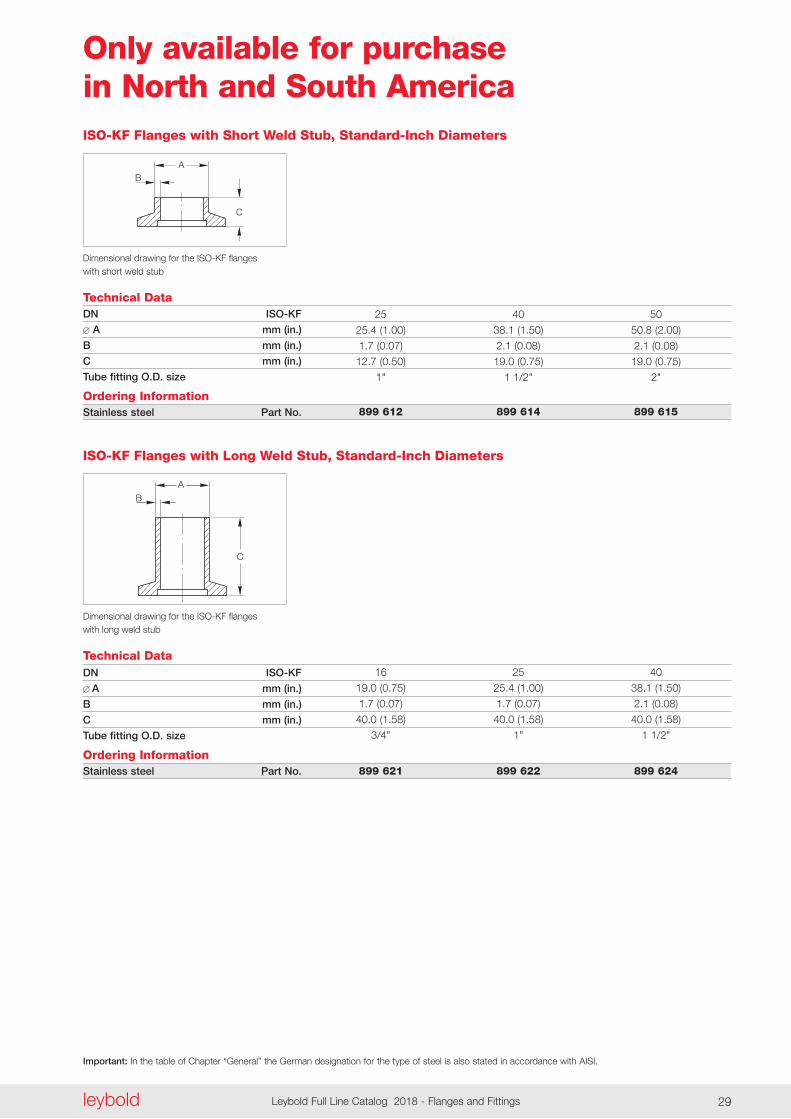
Technical Data
Dimensional drawing for the ISO-KF flanges with short weld stub
DN ISO-KF
A mm (in.)
B mm (in.)
C mm (in.)
Tube fitting O.D. size
Ordering InformationStainless steel Part No.
ISO-KF Flanges with Short Weld Stub, Standard-Inch Diameters
25 40 50
25 .4 (1 .00) 38 .1 (1 .50) 50 .8 (2 .00)
1 .7 (0 .07) 2 .1 (0 .08) 2 .1 (0 .08)
12 .7 (0 .50) 19 .0 (0 .75) 19 .0 (0 .75)
1" 1 1/2" 2"
899 612 899 614 899 615
C
BA
Technical Data
Dimensional drawing for the ISO-KF flanges with long weld stub
DN ISO-KF
A mm (in.)
B mm (in.)
C mm (in.)
Tube fitting O.D. size
Ordering InformationStainless steel Part No.
ISO-KF Flanges with Long Weld Stub, Standard-Inch Diameters
16 25 40
19 .0 (0 .75) 25 .4 (1 .00) 38 .1 (1 .50)
1 .7 (0 .07) 1 .7 (0 .07) 2 .1 (0 .08)
40 .0 (1 .58) 40 .0 (1 .58) 40 .0 (1 .58)
3/4" 1" 1 1/2"
899 621 899 622 899 624
Important: In the table of Chapter “General” the German designation for the type of steel is also stated in accordance with AISI.
leyboldLeybold Full Line Catalog 2018 - Flanges and Fittings30
A
B
C
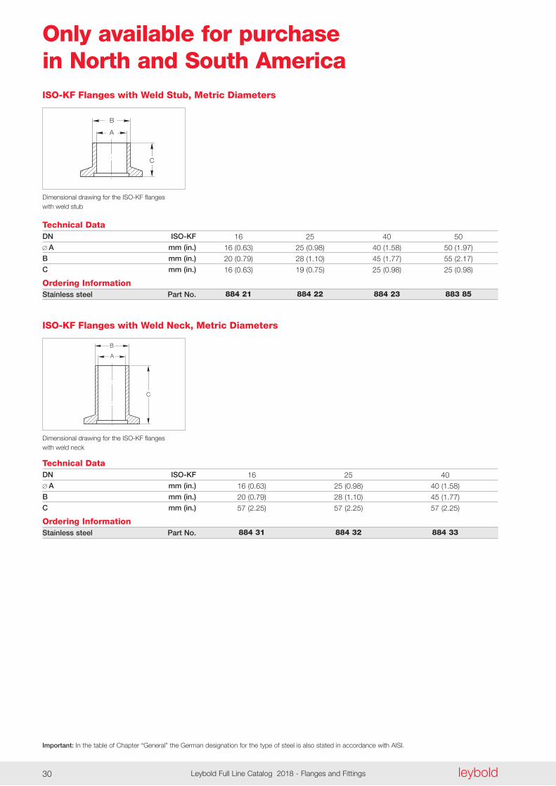
Technical Data
Dimensional drawing for the ISO-KF flanges with weld stub
DN ISO-KF
A mm (in.)
B mm (in.)
C mm (in.)
Ordering InformationStainless steel Part No.
ISO-KF Flanges with Weld Stub, Metric Diameters
16 25 40 50
16 (0 .63) 25 (0 .98) 40 (1 .58) 50 (1 .97)
20 (0 .79) 28 (1 .10) 45 (1 .77) 55 (2 .17)
16 (0 .63) 19 (0 .75) 25 (0 .98) 25 (0 .98)
884 21 884 22 884 23 883 85
C
A
B
Technical Data
Dimensional drawing for the ISO-KF flanges with weld neck
DN ISO-KF
A mm (in.)
B mm (in.)
C mm (in.)
Ordering InformationStainless steel Part No.
ISO-KF Flanges with Weld Neck, Metric Diameters
16 25 40
16 (0 .63) 25 (0 .98) 40 (1 .58)
20 (0 .79) 28 (1 .10) 45 (1 .77)
57 (2 .25) 57 (2 .25) 57 (2 .25)
884 31 884 32 884 33
Only available for purchase in North and South America
Important: In the table of Chapter “General” the German designation for the type of steel is also stated in accordance with AISI.
leyboldLeybold Full Line Catalog 2018 - Flanges and Fittings30 leybold Leybold Full Line Catalog 2018 - Flanges and Fittings 31
Only available for purchase in North and South America
C
A
B
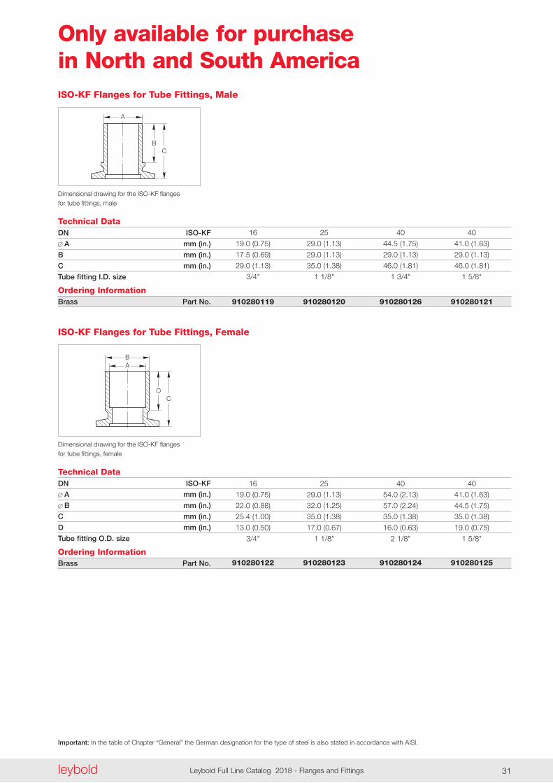
Technical Data
Dimensional drawing for the ISO-KF flanges for tube fittings, male
DN ISO-KF
A mm (in.)
B mm (in.)
C mm (in.)
Tube fitting I.D. size
Ordering InformationBrass Part No.
ISO-KF Flanges for Tube Fittings, Male
16 25 40 40
19 .0 (0 .75) 29 .0 (1 .13) 44 .5 (1 .75) 41 .0 (1 .63)
17 .5 (0 .69) 29 .0 (1 .13) 29 .0 (1 .13) 29 .0 (1 .13)
29 .0 (1 .13) 35 .0 (1 .38) 46 .0 (1 .81) 46 .0 (1 .81)
3/4" 1 1/8" 1 3/4" 1 5/8"
910280119 910280120 910280126 910280121
C
AB
D
Technical Data
Dimensional drawing for the ISO-KF flanges for tube fittings, female
DN ISO-KF
A mm (in.)
B mm (in.)
C mm (in.)
D mm (in.)
Tube fitting O.D. size
Ordering InformationBrass Part No.
ISO-KF Flanges for Tube Fittings, Female
16 25 40 40
19 .0 (0 .75) 29 .0 (1 .13) 54 .0 (2 .13) 41 .0 (1 .63)
22 .0 (0 .88) 32 .0 (1 .25) 57 .0 (2 .24) 44 .5 (1 .75)
25 .4 (1 .00) 35 .0 (1 .38) 35 .0 (1 .38) 35 .0 (1 .38)
13 .0 (0 .50) 17 .0 (0 .67) 16 .0 (0 .63) 19 .0 (0 .75)
3/4" 1 1/8" 2 1/8" 1 5/8"
910280122 910280123 910280124 910280125
Important: In the table of Chapter “General” the German designation for the type of steel is also stated in accordance with AISI.
leyboldLeybold Full Line Catalog 2018 - Flanges and Fittings32
Only available for purchase in North and South America
A
B
C
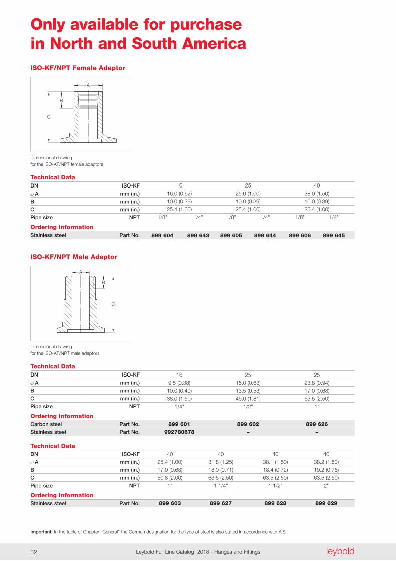
Technical Data
Dimensional drawing for the ISO-KF/NPT female adaptors
DN ISO-KF
A mm (in.)
B mm (in.)
C mm (in.)
Pipe size NPT
Ordering InformationStainless steel Part No.
ISO-KF/NPT Female Adaptor
16 25 40
16 .0 (0 .62) 25 .0 (1 .00) 38 .0 (1 .50)
10 .0 (0 .39) 10 .0 (0 .39) 10 .0 (0 .39)
25 .4 (1 .00) 25 .4 (1 .00) 25 .4 (1 .00)
1/8" 1/4" 1/8" 1/4" 1/8" 1/4"
899 604 899 643 899 605 899 644 899 606 899 645
Technical DataDN ISO-KF
A mm (in.)
B mm (in.)
C mm (in.)
Pipe size NPT
Ordering InformationStainless steel Part No.
40 40 40 40
25 .4 (1 .00) 31 .8 (1 .25) 38 .1 (1 .50) 38 .2 (1 .50)
17 .0 (0 .68) 18 .0 (0 .71) 18 .4 (0 .72) 19 .2 (0 .76)
50 .8 (2 .00) 63 .5 (2 .50) 63 .5 (2 .50) 63 .5 (2 .50)
1" 1 1/4" 1 1/2" 2"
899 603 899 627 899 628 899 629
A
B
C
Technical Data
Dimensional drawing for the ISO-KF/NPT male adaptors
DN ISO-KF
A mm (in.)
B mm (in.)
C mm (in.)
Pipe size NPT
Ordering InformationCarbon steel Part No.
Stainless steel Part No.
ISO-KF/NPT Male Adaptor
16 25 25
9 .5 (0 .38) 16 .0 (0 .63) 23 .8 (0 .94)
10 .0 (0 .40) 13 .5 (0 .53) 17 .0 (0 .68)
38 .0 (1 .50) 46 .0 (1 .81) 63 .5 (2 .50)
1/4" 1/2" 1"
899 601 899 602 899 626 992780678 – –
Important: In the table of Chapter “General” the German designation for the type of steel is also stated in accordance with AISI.
leyboldLeybold Full Line Catalog 2018 - Flanges and Fittings32 leybold Leybold Full Line Catalog 2018 - Flanges and Fittings 33
Only available for purchase in North and South America
C
B
A
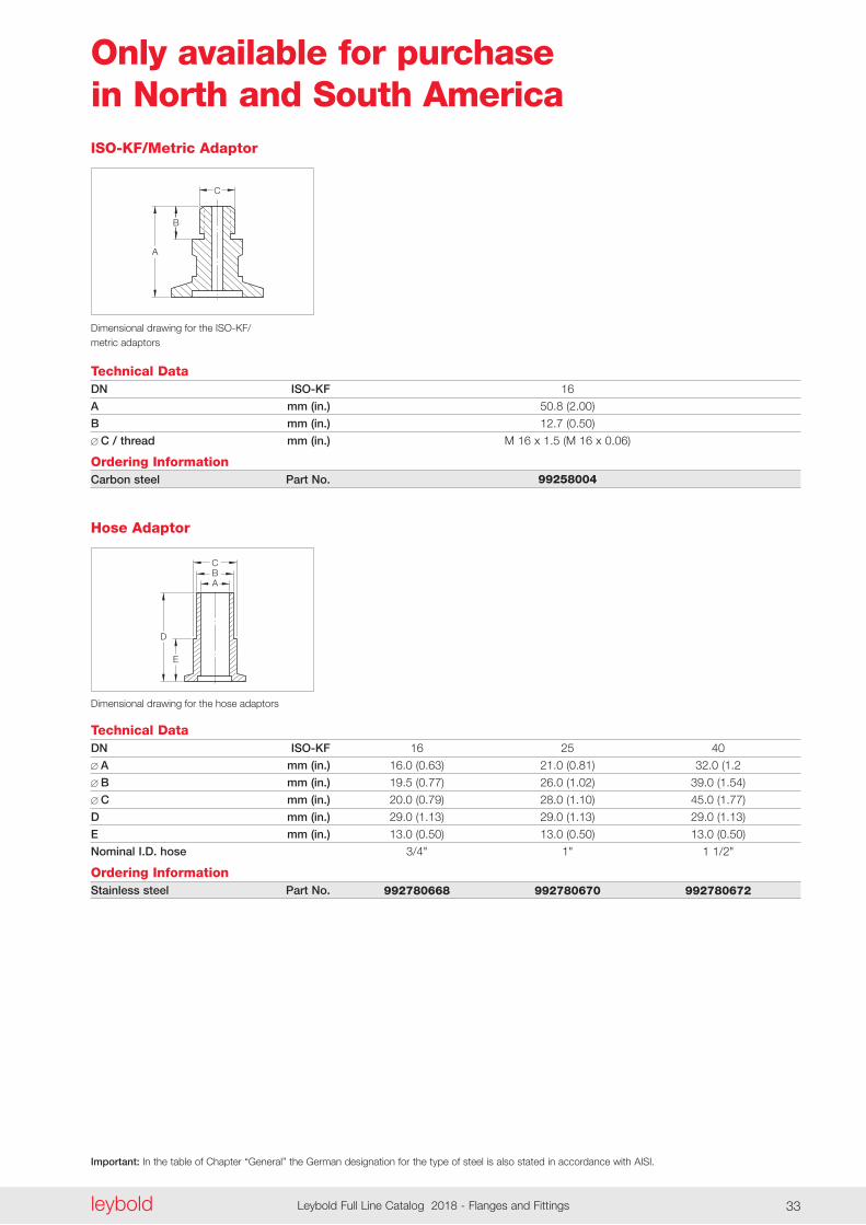
Technical Data
Dimensional drawing for the ISO-KF/ metric adaptors
DN ISO-KF
A mm (in.)
B mm (in.)
C / thread mm (in.)
Ordering InformationCarbon steel Part No.
ISO-KF/Metric Adaptor
16
50 .8 (2 .00)
12 .7 (0 .50)
M 16 x 1 .5 (M 16 x 0 .06)
99258004
E
D
ABC
Technical Data
Dimensional drawing for the hose adaptors
DN ISO-KF
A mm (in.)
B mm (in.)
C mm (in.)
D mm (in.)
E mm (in.)
Nominal I.D. hose
Ordering InformationStainless steel Part No.
Hose Adaptor
16 25 40
16 .0 (0 .63) 21 .0 (0 .81) 32 .0 (1 .2
19 .5 (0 .77) 26 .0 (1 .02) 39 .0 (1 .54)
20 .0 (0 .79) 28 .0 (1 .10) 45 .0 (1 .77)
29 .0 (1 .13) 29 .0 (1 .13) 29 .0 (1 .13)
13 .0 (0 .50) 13 .0 (0 .50) 13 .0 (0 .50)
3/4" 1" 1 1/2"
992780668 992780670 992780672
leyboldLeybold Full Line Catalog 2018 - Flanges and Fittings34
Important: In the table of Chapter “General” the German designation for the type of steel is also stated in accordance with AISI.
leyboldLeybold Full Line Catalog 2018 - Flanges and Fittings34
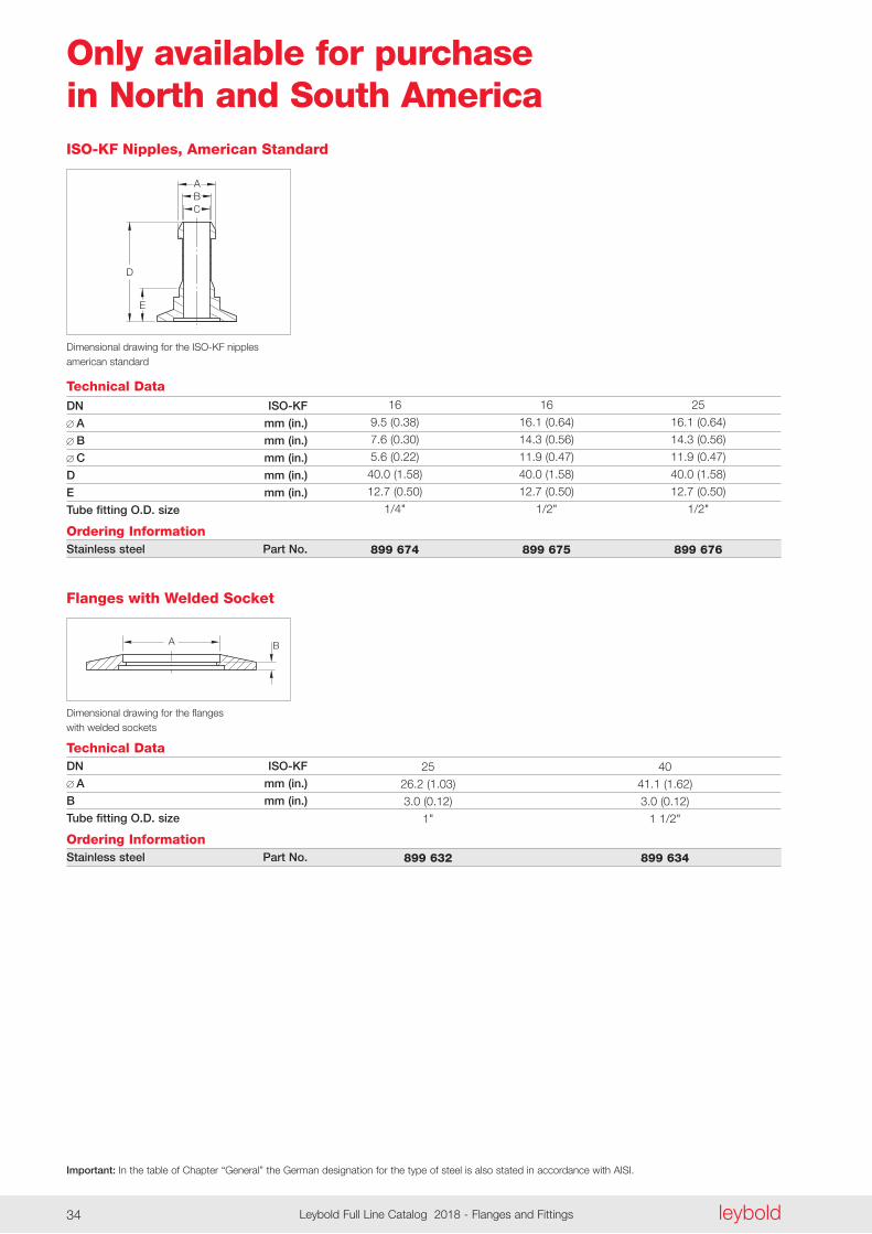
Only available for purchase in North and South America
A B
Technical Data
Dimensional drawing for the flanges with welded sockets
DN ISO-KF
A mm (in.)
B mm (in.)
Tube fitting O.D. size
Ordering InformationStainless steel Part No.
Flanges with Welded Socket
25 40
26 .2 (1 .03) 41 .1 (1 .62)
3 .0 (0 .12) 3 .0 (0 .12)
1" 1 1/2"
899 632 899 634
C
D
E
BA
Technical Data
Dimensional drawing for the ISO-KF nipples american standard
DN ISO-KF
A mm (in.)
B mm (in.)
C mm (in.)
D mm (in.)
E mm (in.)
Tube fitting O.D. size
Ordering InformationStainless steel Part No.
ISO-KF Nipples, American Standard
16 16 25
9 .5 (0 .38) 16 .1 (0 .64) 16 .1 (0 .64)
7 .6 (0 .30) 14 .3 (0 .56) 14 .3 (0 .56)
5 .6 (0 .22) 11 .9 (0 .47) 11 .9 (0 .47)
40 .0 (1 .58) 40 .0 (1 .58) 40 .0 (1 .58)
12 .7 (0 .50) 12 .7 (0 .50) 12 .7 (0 .50)
1/4" 1/2" 1/2"
899 674 899 675 899 676
Notes
leyboldLeybold Full Line Catalog 2018 - Flanges and Fittings34 leybold Leybold Full Line Catalog 2018 - Flanges and Fittings 35leyboldLeybold Full Line Catalog 2018 - Flanges and Fittings34
Important: In the table of Chapter “General” the German designation for the type of steel is also stated in accordance with AISI.
leyboldLeybold Full Line Catalog 2018 - Flanges and Fittings36
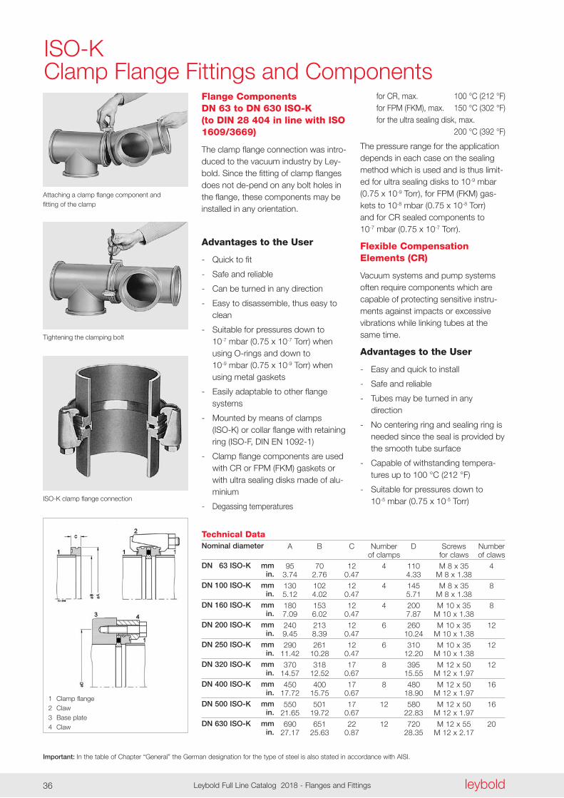
ISO-KClamp Flange Fittings and Components
Attaching a clamp flange component and fitting of the clamp
Flange Components DN 63 to DN 630 ISO-K (to DIN 28 404 in line with ISO 1609/3669)
The clamp flange connection was intro-duced to the vacuum industry by Ley-bold . Since the fitting of clamp flanges does not de-pend on any bolt holes in the flange, these components may be installed in any orien tation .
Advantages to the User
- Quick to fit
- Safe and reliable
- Can be turned in any direction
- Easy to disassemble, thus easy to clean
- Suitable for pressures down to 10-7 mbar (0 .75 x 10-7 Torr) when using O-rings and down to 10-9 mbar (0 .75 x 10-9 Torr) when using metal gaskets
- Easily adaptable to other flange systems
- Mounted by means of clamps (ISO-K) or collar flange with retaining ring (ISO-F, DIN EN 1092-1)
- Clamp flange components are used with CR or FPM (FKM) gaskets or with ultra sealing disks made of alu-minium
- Degassing temperatures
Tightening the clamping bolt
ISO-K clamp flange connection
Technical DataNominal diameter
DN 063 ISO-K mm in.
DN 100 ISO-K mm in.
DN 160 ISO-K mm in.
DN 200 ISO-K mm in.
DN 250 ISO-K mm in.
DN 320 ISO-K mm in.
DN 400 ISO-K mm in.
DN 500 ISO-K mm in.
DN 630 ISO-K mm in.
A B C Number D Screws Number of clamps for claws of claws
95 70 12 4 110 M 8 x 35 4 3 .74 2 .76 0 .47 4 .33 M 8 x 1 .38
130 102 12 4 145 M 8 x 35 8 5 .12 4 .02 0 .47 5 .71 M 8 x 1 .38
180 153 12 4 200 M 10 x 35 8 7 .09 6 .02 0 .47 7 .87 M 10 x 1 .38
240 213 12 6 260 M 10 x 35 12 9 .45 8 .39 0 .47 10 .24 M 10 x 1 .38
290 261 12 6 310 M 10 x 35 12 11 .42 10 .28 0 .47 12 .20 M 10 x 1 .38
370 318 17 8 395 M 12 x 50 12 14 .57 12 .52 0 .67 15 .55 M 12 x 1 .97
450 400 17 8 480 M 12 x 50 16 17 .72 15 .75 0 .67 18 .90 M 12 x 1 .97
550 501 17 12 580 M 12 x 50 16 21 .65 19 .72 0 .67 22 .83 M 12 x 1 .97
690 651 22 12 720 M 12 x 55 20 27 .17 25 .63 0 .87 28 .35 M 12 x 2 .17
for CR, max . 100 °C (212 °F) for FPM (FKM), max . 150 °C (302 °F) for the ultra sealing disk, max . 200 °C (392 °F)
The pressure range for the applica tion depends in each case on the sealing method which is used and is thus limit-ed for ultra sealing disks to 10-9 mbar (0 .75 x 10-9 Torr), for FPM (FKM) gas-kets to 10-8 mbar (0 .75 x 10-8 Torr) and for CR sealed components to 10-7 mbar (0 .75 x 10-7 Torr) .
Flexible Compensation Elements (CR)
Vacuum systems and pump systems often require components which are capable of protecting sensitive instru - ments against impacts or excessive vibrations while linking tubes at the same time .
Advantages to the User
- Easy and quick to install
- Safe and reliable
- Tubes may be turned in any direction
- No centering ring and sealing ring is needed since the seal is provided by the smooth tube surface
- Capable of withstanding tempera-tures up to 100 °C (212 °F)
- Suitable for pressures down to 10-5 mbar (0 .75 x 10-5 Torr)
1 Clamp flange 2 Claw 3 Base plate 4 Claw
h
d1
d2
ds
Important: In the table of Chapter “General” the German designation for the type of steel is also stated in accordance with AISI.
leyboldLeybold Full Line Catalog 2018 - Flanges and Fittings36 leybold Leybold Full Line Catalog 2018 - Flanges and Fittings 37
Technical DataDN ISO-K
d mm (in.)
d1 mm (in.)
d2 mm (in.)
h mm (in.)
s mm (in.)
Ordering InformationAluminium/FPM (FKM) Part No.
Aluminium/CR Part No.
Stainless steel/FPM (FKM) 1) Part No.
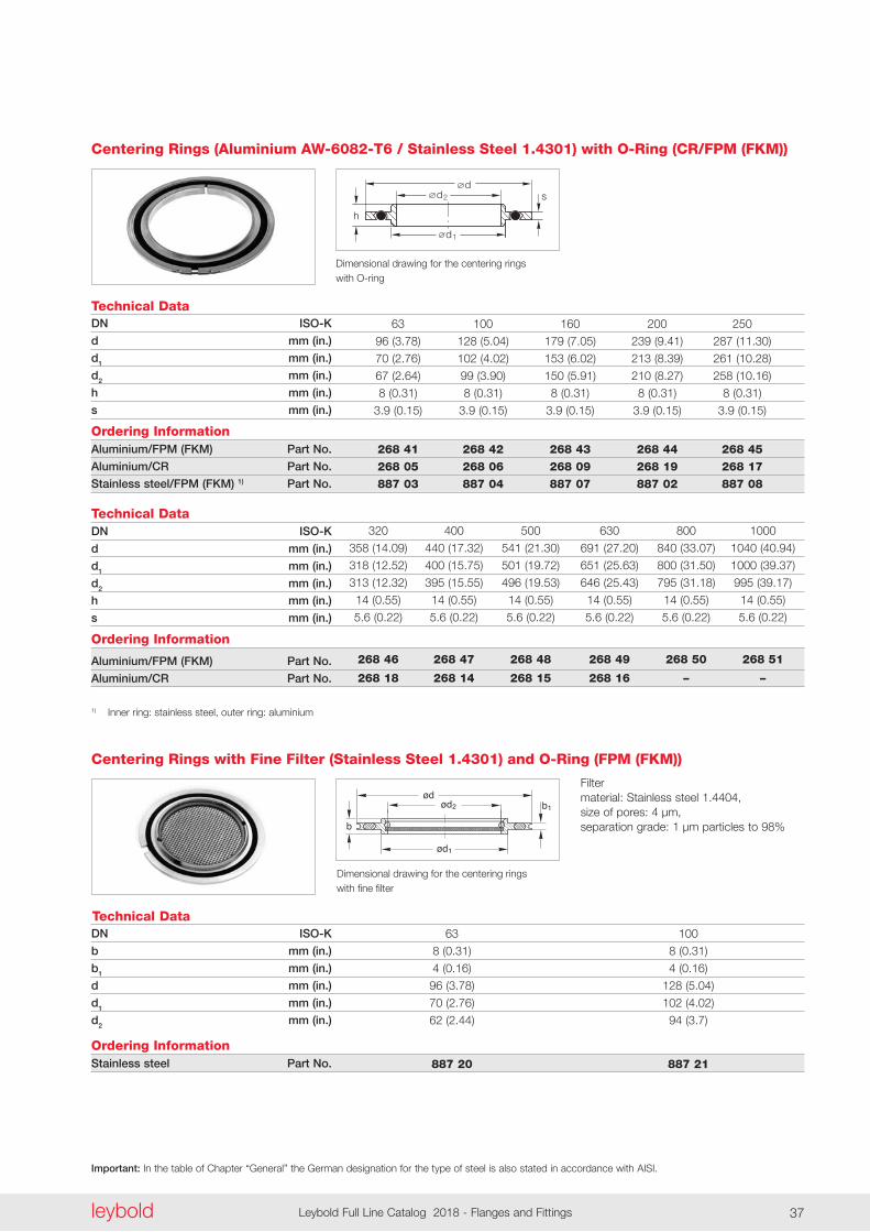
Centering Rings (Aluminium AW-6082-T6 / Stainless Steel 1.4301) with O-Ring (CR/FPM (FKM))
63 100 160 200 250
96 (3 .78) 128 (5 .04) 179 (7 .05) 239 (9 .41) 287 (11 .30)
70 (2 .76) 102 (4 .02) 153 (6 .02) 213 (8 .39) 261 (10 .28)
67 (2 .64) 99 (3 .90) 150 (5 .91) 210 (8 .27) 258 (10 .16)
8 (0 .31) 8 (0 .31) 8 (0 .31) 8 (0 .31) 8 (0 .31)
3 .9 (0 .15) 3 .9 (0 .15) 3 .9 (0 .15) 3 .9 (0 .15) 3 .9 (0 .15)
268 41 268 42 268 43 268 44 268 45 268 05 268 06 268 09 268 19 268 17 887 03 887 04 887 07 887 02 887 08
Dimensional drawing for the centering rings with O-ring
Technical DataDN ISO-K
d mm (in.)
d1 mm (in.)
d2 mm (in.)
h mm (in.)
s mm (in.)
Ordering Information
Aluminium/FPM (FKM) Part No.
Aluminium/CR Part No.
1) Inner ring: stainless steel, outer ring: aluminium
320 400 500 630 800 1000
358 (14 .09) 440 (17 .32) 541 (21 .30) 691 (27 .20) 840 (33 .07) 1040 (40 .94)
318 (12 .52) 400 (15 .75) 501 (19 .72) 651 (25 .63) 800 (31 .50) 1000 (39 .37)
313 (12 .32) 395 (15 .55) 496 (19 .53) 646 (25 .43) 795 (31 .18) 995 (39 .17)
14 (0 .55) 14 (0 .55) 14 (0 .55) 14 (0 .55) 14 (0 .55) 14 (0 .55)
5 .6 (0 .22) 5 .6 (0 .22) 5 .6 (0 .22) 5 .6 (0 .22) 5 .6 (0 .22) 5 .6 (0 .22)
268 46 268 47 268 48 268 49 268 50 268 51
268 18 268 14 268 15 268 16 – –
ødød2
ød1
b
b1
07.01.M.047E
Technical DataDN ISO-K
b mm (in.)
b1 mm (in.)
d mm (in.)
d1 mm (in.)
d2 mm (in.)
Ordering InformationStainless steel Part No.
Centering Rings with Fine Filter (Stainless Steel 1.4301) and O-Ring (FPM (FKM))
63 100
8 (0 .31) 8 (0 .31)
4 (0 .16) 4 (0 .16)
96 (3 .78) 128 (5 .04)
70 (2 .76) 102 (4 .02)
62 (2 .44) 94 (3 .7)
887 20 887 21
Dimensional drawing for the centering rings with fine filter
Filter material: Stainless steel 1 .4404, size of pores: 4 µm, separation grade: 1 µm particles to 98%
Important: In the table of Chapter “General” the German designation for the type of steel is also stated in accordance with AISI.
leyboldLeybold Full Line Catalog 2018 - Flanges and Fittings38
b
2d
3d1d
d
Technical DataDN ISO-K
b mm (in.)
d mm (in.)
d1 mm (in.)
d2 mm (in.)
d3 mm (in.)
Ordering InformationAluminium/FPM (FKM) Part No.
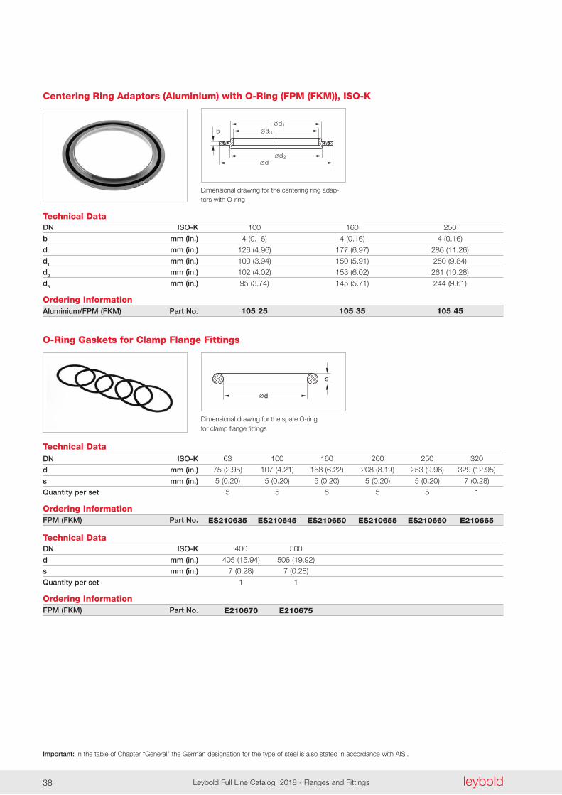
Centering Ring Adaptors (Aluminium) with O-Ring (FPM (FKM)), ISO-K
100 160 250
4 (0 .16) 4 (0 .16) 4 (0 .16)
126 (4 .96) 177 (6 .97) 286 (11 .26)
100 (3 .94) 150 (5 .91) 250 (9 .84)
102 (4 .02) 153 (6 .02) 261 (10 .28)
95 (3 .74) 145 (5 .71) 244 (9 .61)
105 25 105 35 105 45
Dimensional drawing for the centering ring adap-tors with O-ring
d
s
Technical DataDN ISO-K
d mm (in.)
s mm (in.)
Quantity per set
Ordering InformationFPM (FKM) Part No.
63 100 160 200 250 320
75 (2 .95) 107 (4 .21) 158 (6 .22) 208 (8 .19) 253 (9 .96) 329 (12 .95)
5 (0 .20) 5 (0 .20) 5 (0 .20) 5 (0 .20) 5 (0 .20) 7 (0 .28)
5 5 5 5 5 1
ES210635 ES210645 ES210650 ES210655 ES210660 E210665
O-Ring Gaskets for Clamp Flange Fittings
Dimensional drawing for the spare O-ring for clamp flange fittings
Technical DataDN ISO-K
d mm (in.)
s mm (in.)
Quantity per set
Ordering InformationFPM (FKM) Part No.
400 500
405 (15 .94) 506 (19 .92)
7 (0 .28) 7 (0 .28)
1 1
E210670 E210675
Important: In the table of Chapter “General” the German designation for the type of steel is also stated in accordance with AISI.
leyboldLeybold Full Line Catalog 2018 - Flanges and Fittings38 leybold Leybold Full Line Catalog 2018 - Flanges and Fittings 39
d
1d
bb 1
Technical DataDN ISO-K / ISO-F
b mm (in.)
b1 mm (in.)
d mm (in.)
d1 mm (in.)
Ordering InformationAluminium Part No.1) Only for collar ring connections
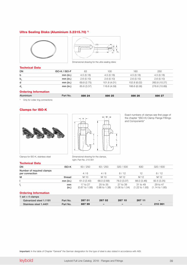
Ultra Sealing Disks (Aluminium 3.2315.70) 1)
63 100 160 250
4 .5 (0 .18) 4 .5 (0 .18) 4 .5 (0 .18) 4 .5 (0 .18)
2 .6 (0 .10) 2 .6 (0 .10) 2 .6 (0 .10) 2 .6 (0 .10)
69 .8 (2 .75) 101 .8 (4 .01) 152 .8 (6 .02) 260 .8 (10 .27)
85 .6 (3 .37) 116 .6 (4 .59) 166 .6 (6 .56) 276 .6 (10 .89)
886 24 886 25 886 26 886 27
Dimensional drawing for the ultra sealing disks
l
l
1
M
l
M
l3
l2
2,5
07.01.M.073-Klammer(Neu)
l
M
l1
Technical DataDN ISO-K
Number of required clamps per connection
M thread
l mm (in.)
l1 mm (in.)
Ordering Information1 set = 4 clamps
Galvanized steel 1.1181 Part No.
Stainless steel 1.4401 Part No.
63 / 250 63 / 250 320 / 500 630 320 / 630
4 / 6 4 / 6 8 / 12 12 8 / 12
M 10 M 10 M 12 M 12 M 12
61 .0 (2 .40) 68 .0 (2 .68) 78 .0 (3 .07) 88 .0 (3 .46) 82 .5 (3 .25)
17 to 27 25 to 35 27 to 39 31 to 49 29 to 47 (0 .67 to 1 .06) 0 .98 to 1 .38) (1 .06 to 1 .54) (1 .22 to 1 .93) (1 .14 to 1 .85)
267 01 267 02 267 10 267 11 – 887 99 – – – 210 061
Clamps for ISO-K
Dimensional drawing for the clamps, right: Part No . 210 061
Clamps for ISO-K, stainless steel
Exact numbers of clamps see first page of the chapter “(ISO-K) Clamp Flange Fittings and Components”
Important: In the table of Chapter “General” the German designation for the type of steel is also stated in accordance with AISI.
leyboldLeybold Full Line Catalog 2018 - Flanges and Fittings40
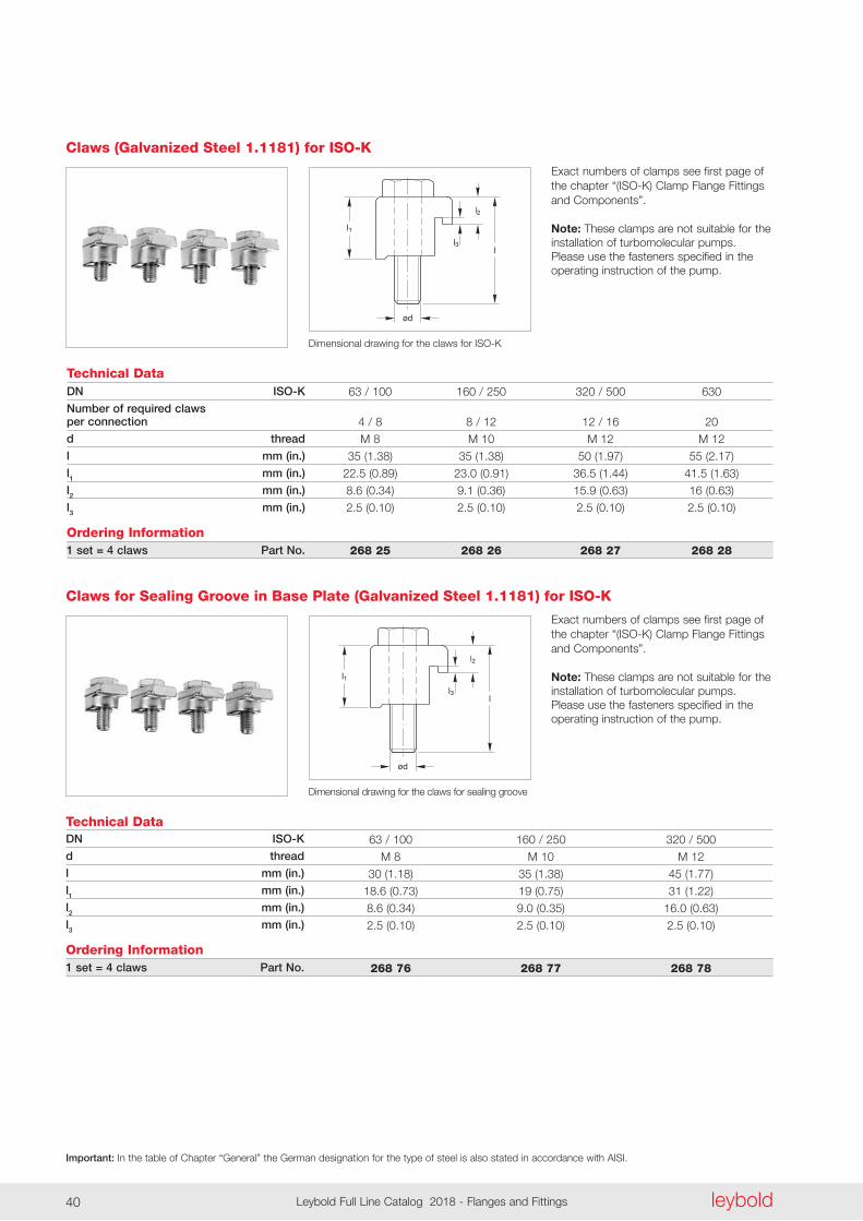
Exact numbers of clamps see first page of the chapter “(ISO-K) Clamp Flange Fittings and Components” .
Note: These clamps are not suitable for the installation of turbomolecular pumps . Please use the fasteners specified in the operating instruction of the pump .
l1
ød
l2
ll3
07.01.M.020-E (Pratzen)
Technical DataDN ISO-K
Number of required claws per connection
d thread
l mm (in.)
l1 mm (in.)
l2 mm (in.)
l3 mm (in.)
Ordering Information1 set = 4 claws Part No.
63 / 100 160 / 250 320 / 500 630
4 / 8 8 / 12 12 / 16 20
M 8 M 10 M 12 M 12
35 (1 .38) 35 (1 .38) 50 (1 .97) 55 (2 .17)
22 .5 (0 .89) 23 .0 (0 .91) 36 .5 (1 .44) 41 .5 (1 .63)
8 .6 (0 .34) 9 .1 (0 .36) 15 .9 (0 .63) 16 (0 .63)
2 .5 (0 .10) 2 .5 (0 .10) 2 .5 (0 .10) 2 .5 (0 .10)
268 25 268 26 268 27 268 28
Claws (Galvanized Steel 1.1181) for ISO-K
Dimensional drawing for the claws for ISO-K
l1
ød
l2
ll3
07.01.M.020-E (Pratzen)
Technical DataDN ISO-K
d thread
l mm (in.)
l1 mm (in.)
l2 mm (in.)
l3 mm (in.)
Ordering Information1 set = 4 claws Part No.
63 / 100 160 / 250 320 / 500
M 8 M 10 M 12
30 (1 .18) 35 (1 .38) 45 (1 .77)
18 .6 (0 .73) 19 (0 .75) 31 (1 .22)
8 .6 (0 .34) 9 .0 (0 .35) 16 .0 (0 .63)
2 .5 (0 .10) 2 .5 (0 .10) 2 .5 (0 .10)
268 76 268 77 268 78
Claws for Sealing Groove in Base Plate (Galvanized Steel 1.1181) for ISO-K
Dimensional drawing for the claws for sealing groove
Exact numbers of clamps see first page of the chapter “(ISO-K) Clamp Flange Fittings and Components” .
Note: These clamps are not suitable for the installation of turbomolecular pumps . Please use the fasteners specified in the operating instruction of the pump .
Important: In the table of Chapter “General” the German designation for the type of steel is also stated in accordance with AISI.
leyboldLeybold Full Line Catalog 2018 - Flanges and Fittings40 leybold Leybold Full Line Catalog 2018 - Flanges and Fittings 41
d1
b
d
t1 t ød2
b1 a
07.01.M.013-E (Blindflansch)
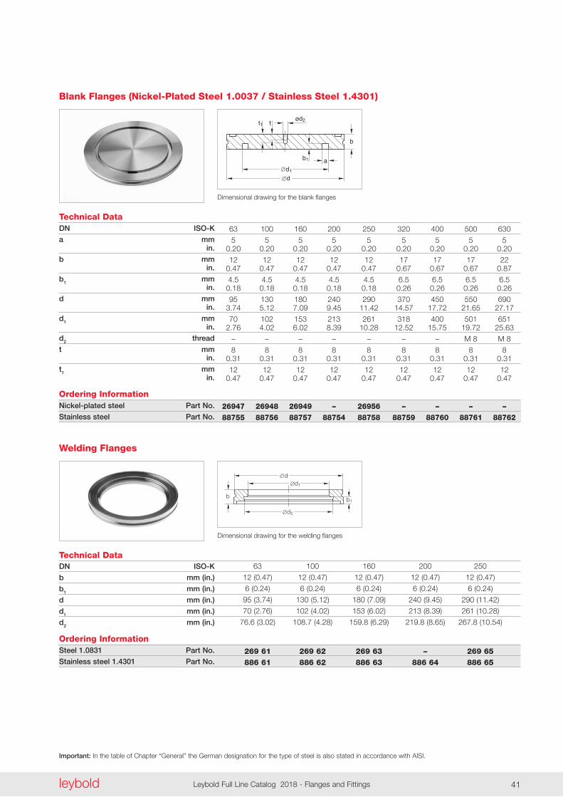
Technical DataDN ISO-K
a mm in.
b mm in.
b1 mm in.
d mm in.
d1 mm in.
d2 thread
t mm in.
t1 mm in.
Ordering InformationNickel-plated steel Part No.
Stainless steel Part No.
63 100 160 200 250 320 400 500 630
5 5 5 5 5 5 5 5 5 0 .20 0 .20 0 .20 0 .20 0 .20 0 .20 0 .20 0 .20 0 .20
12 12 12 12 12 17 17 17 22 0 .47 0 .47 0 .47 0 .47 0 .47 0 .67 0 .67 0 .67 0 .87
4 .5 4 .5 4 .5 4 .5 4 .5 6 .5 6 .5 6 .5 6 .5 0 .18 0 .18 0 .18 0 .18 0 .18 0 .26 0 .26 0 .26 0 .26
95 130 180 240 290 370 450 550 690 3 .74 5 .12 7 .09 9 .45 11 .42 14 .57 17 .72 21 .65 27 .17
70 102 153 213 261 318 400 501 651 2 .76 4 .02 6 .02 8 .39 10 .28 12 .52 15 .75 19 .72 25 .63
– – – – – – – M 8 M 8
8 8 8 8 8 8 8 8 8 0 .31 0 .31 0 .31 0 .31 0 .31 0 .31 0 .31 0 .31 0 .31
12 12 12 12 12 12 12 12 12 0 .47 0 .47 0 .47 0 .47 0 .47 0 .47 0 .47 0 .47 0 .47
26947 26948 26949 – 26956 – – – – 88755 88756 88757 88754 88758 88759 88760 88761 88762
Blank Flanges (Nickel-Plated Steel 1.0037 / Stainless Steel 1.4301)
Dimensional drawing for the blank flanges
d1
d2
d
b b1
Technical DataDN ISO-K
b mm (in.)
b1 mm (in.)
d mm (in.)
d1 mm (in.)
d2 mm (in.)
Ordering InformationSteel 1.0831 Part No.
Stainless steel 1.4301 Part No.
63 100 160 200 250
12 (0 .47) 12 (0 .47) 12 (0 .47) 12 (0 .47) 12 (0 .47)
6 (0 .24) 6 (0 .24) 6 (0 .24) 6 (0 .24) 6 (0 .24)
95 (3 .74) 130 (5 .12) 180 (7 .09) 240 (9 .45) 290 (11 .42)
70 (2 .76) 102 (4 .02) 153 (6 .02) 213 (8 .39) 261 (10 .28)
76 .6 (3 .02) 108 .7 (4 .28) 159 .8 (6 .29) 219 .8 (8 .65) 267 .8 (10 .54)
269 61 269 62 269 63 – 269 65 886 61 886 62 886 63 886 64 886 65
Welding Flanges
Dimensional drawing for the welding flanges
Important: In the table of Chapter “General” the German designation for the type of steel is also stated in accordance with AISI.
leyboldLeybold Full Line Catalog 2018 - Flanges and Fittings42
d2
s
d1d
b
h
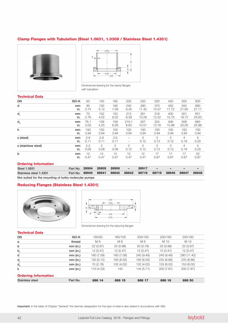
Technical DataDN ISO-K
d mm in.
d1 mm in.
d2 mm in.
h mm in.
s (steel) mm in.
s (stainless steel) mm in.
b mm in.
Ordering InformationSteel 1.0831 Part No.
Stainless steel 1.4301 Part No.
Not suited for the mounting of turbo molecular pumps
63 100 160 200 250 320 400 500 630
95 130 180 240 290 370 450 550 690 3 .74 5 .12 7 .09 9 .45 11 .42 14 .57 17 .72 21 .65 27 .17
70 102 153 213 261 318 400 501 651 2 .76 4 .02 6 .02 8 .39 10 .28 12 .52 15 .75 19 .72 25 .63
76 .1 108 159 219 .1 267 324 406 508 660 3 .00 4 .25 6 .26 8 .63 10 .51 12 .76 15 .98 20 .00 25 .98
100 100 100 100 100 100 100 100 100 3 .94 3 .94 3 .94 3 .94 3 .94 3 .94 3 .94 3 .94 3 .94
2 .9 2 .9 2 .9 – 3 3 3 4 5 0 .11 0 .11 0 .11 – 0 .12 0 .12 0 .12 0 .16 0 .20
2 .3 2 2 3 3 3 3 4 5 0 .09 0 .08 0 .08 0 .12 0 .12 0 .12 0 .12 0 .16 0 .20
12 12 12 12 12 17 17 17 22 0 .47 0 .47 0 .47 0 .47 0 .47 0 .67 0 .67 0 .67 0 .87
26904 26905 26906 – 26917 – – – – 88640 88641 88642 88643 88718 88719 88646 88647 88648
Clamp Flanges with Tubulation (Steel 1.0831, 1.0308 / Stainless Steel 1.4301)
Dimensional drawing for the clamp flanges with tubulation
d2
a k
d
1
d
b b
1
Technical DataDN ISO-K
a thread
b mm (in.)
b1 mm (in.)
d mm (in.)
d1 mm (in.)
d2 mm (in.)
k mm (in.)
Ordering InformationStainless steel Part No.
160/63 160/100 200/100 200/160 250/160
M 8 M 8 M 8 M 10 M 10
22 (0 .87) 25 (0 .98) 20 (0 .79) 25 (0 .98) 22 (0 .87)
12 (0 .47) 12 (0 .47) 12 (0 .47) 12 (0 .47) 12 (0 .47)
180 (7 .09) 180 (7 .09) 240 (9 .49) 240 (9 .49) 290 (11 .42)
130 (5 .12) 165 (6 .50) 165 (6 .50) 225 (8 .86) 225 (8 .86)
70 (2 .76) 102 (4 .02) 102 (4 .02) 153 (6 .02) 153 (6 .02)
110 (4 .33) 145 145 (5 .71) 200 (7 .87) 200 (7 .87)
886 14 886 15 886 17 886 16 886 50
Reducing Flanges (Stainless Steel 1.4301)
Dimensional drawing for the reducing flanges
Important: In the table of Chapter “General” the German designation for the type of steel is also stated in accordance with AISI.
leyboldLeybold Full Line Catalog 2018 - Flanges and Fittings42 leybold Leybold Full Line Catalog 2018 - Flanges and Fittings 43
d1
h
d
DN1
DN
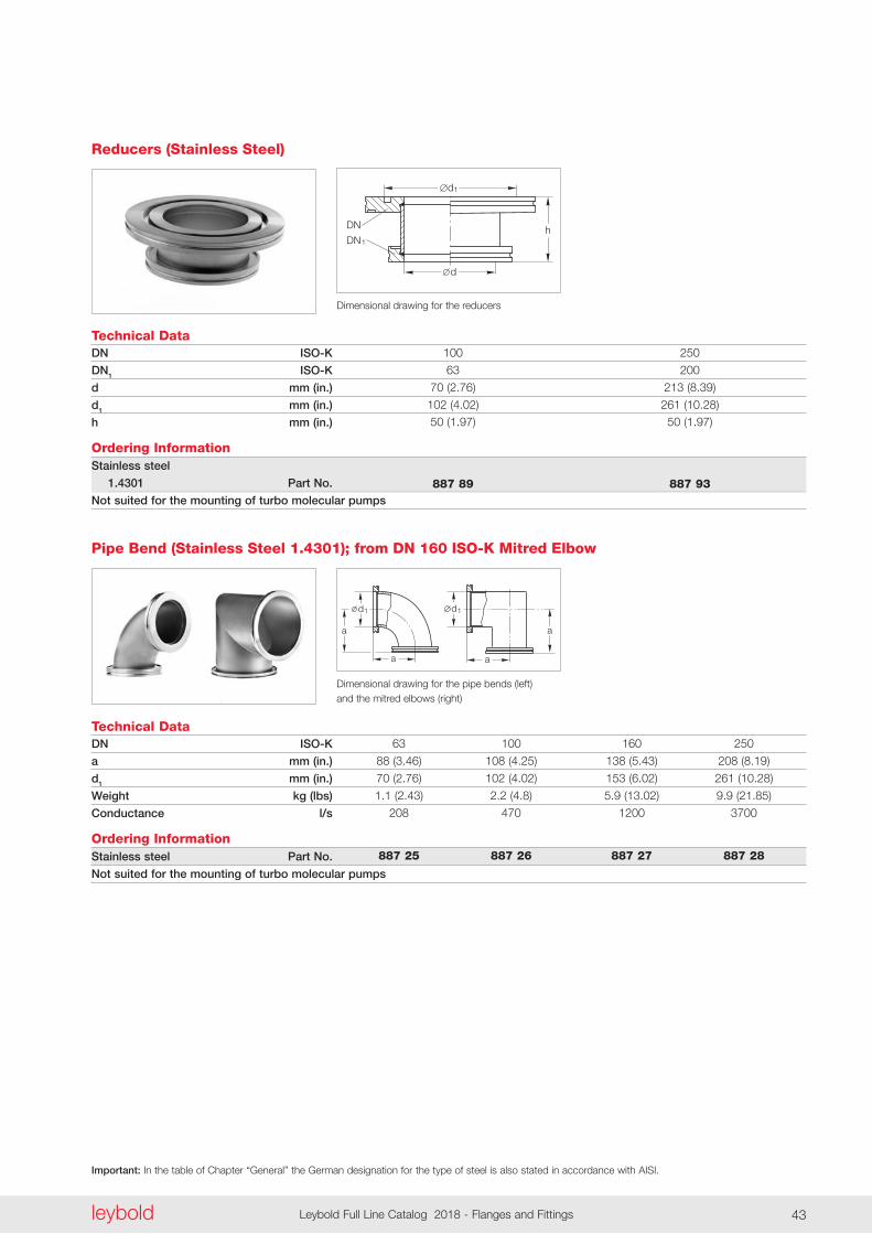
Technical DataDN ISO-K
DN1 ISO-K
d mm (in.)
d1 mm (in.)
h mm (in.)
Ordering InformationStainless steel
1.4301 Part No.
Not suited for the mounting of turbo molecular pumps
100 250
63 200
70 (2 .76) 213 (8 .39)
102 (4 .02) 261 (10 .28) 50 (1 .97) 50 (1 .97)
887 89 887 93
Reducers (Stainless Steel)
Dimensional drawing for the reducers
Technical DataDN ISO-K
a mm (in.)
d1 mm (in.)
Weight kg (lbs)
Conductance l/s
Ordering InformationStainless steel Part No.
Not suited for the mounting of turbo molecular pumps
63 100 160 250
88 (3 .46) 108 (4 .25) 138 (5 .43) 208 (8 .19)
70 (2 .76) 102 (4 .02) 153 (6 .02) 261 (10 .28)
1 .1 (2 .43) 2 .2 (4 .8) 5 .9 (13 .02) 9 .9 (21 .85)
208 470 1200 3700
887 25 887 26 887 27 887 28
Pipe Bend (Stainless Steel 1.4301); from DN 160 ISO-K Mitred Elbow
d1
a
a
d1
a
a
d1
a
a
d1
a
a
Dimensional drawing for the pipe bends (left) and the mitred elbows (right)
Important: In the table of Chapter “General” the German designation for the type of steel is also stated in accordance with AISI.
leyboldLeybold Full Line Catalog 2018 - Flanges and Fittings44
Technical DataDN ISO-K
a mm (in.)
b mm (in.)
d1 mm (in.)
Weight kg (lbs)
Ordering InformationStainless steel Part No.
Not suited for the mounting of turbo molecular pumps
63 100 160 250
88 (3 .46) 108 (4 .25) 138 (5 .43) 208 (8 .19)
176 (6 .93) 216 (8 .50) 276 (10 .87) 416 (16 .38)
70 (2 .76) 102 (4 .02) 153 (6 .02) 261 (10 .28)
1 .6 (3 .53) 3 .2 (7 .06) 7 .6 (16 .78) 8 .1 (17 .88)
887 35 887 36 887 37 887 38
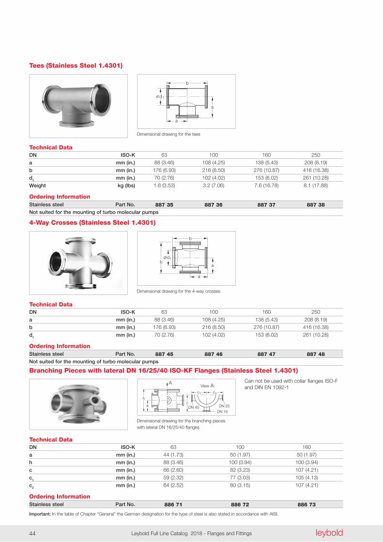
Tees (Stainless Steel 1.4301)
d
b
1
a
a
Dimensional drawing for the tees
d1
b
a
a
b
Technical DataDN ISO-K
a mm (in.)
b mm (in.)
d1 mm (in.)
Ordering InformationStainless steel Part No.
Not suited for the mounting of turbo molecular pumps
63 100 160 250
88 (3 .46) 108 (4 .25) 138 (5 .43) 208 (8 .19)
176 (6 .93) 216 (8 .50) 276 (10 .87) 416 (16 .38)
70 (2 .76) 102 (4 .02) 153 (6 .02) 261 (10 .28)
887 45 887 46 887 47 887 48
4-Way Crosses (Stainless Steel 1.4301)
Dimensional drawing for the 4-way crosses
Can not be used with collar flanges ISO-F and DIN EN 1092-1
h
A Ansicht: A
ac
c c
DN 25DN 40DN 16
1 2
Technical DataDN ISO-K
a mm (in.)
h mm (in.)
c mm (in.)
c1 mm (in.)
c2 mm (in.)
Ordering InformationStainless steel Part No.
63 100 160
44 (1 .73) 50 (1 .97) 50 (1 .97)
88 (3 .46) 100 (3 .94) 100 (3 .94)
66 (2 .60) 82 (3 .23) 107 (4 .21)
59 (2 .32) 77 (3 .03) 105 (4 .13)
64 (2 .52) 80 (3 .15) 107 (4 .21)
886 71 886 72 886 73
Branching Pieces with lateral DN 16/25/40 ISO-KF Flanges (Stainless Steel 1.4301)
Dimensional drawing for the branching pieces with lateral DN 16/25/40 flanges
View A:
Important: In the table of Chapter “General” the German designation for the type of steel is also stated in accordance with AISI.
leyboldLeybold Full Line Catalog 2018 - Flanges and Fittings44 leybold Leybold Full Line Catalog 2018 - Flanges and Fittings 45
l
d1s t
d
DN1
DN
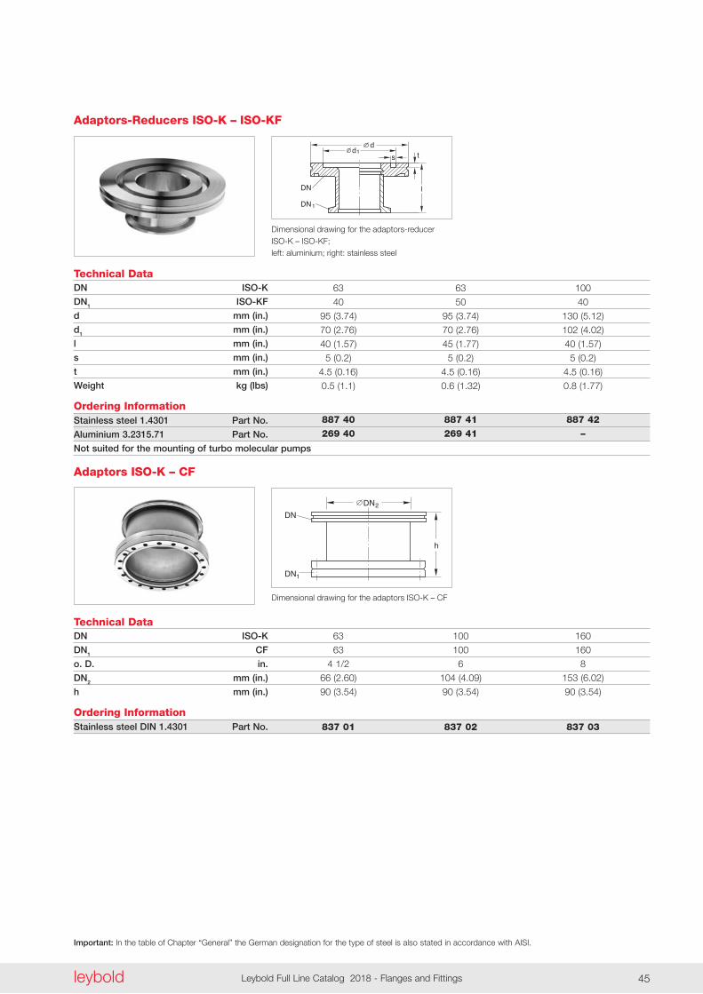
Technical DataDN ISO-K
DN1 ISO-KF
d mm (in.)
d1 mm (in.)
l mm (in.)
s mm (in.)
t mm (in.)
Weight kg (lbs)
Ordering InformationStainless steel 1.4301 Part No.
Aluminium 3.2315.71 Part No.
Not suited for the mounting of turbo molecular pumps
63 63 100
40 50 40
95 (3 .74) 95 (3 .74) 130 (5 .12)
70 (2 .76) 70 (2 .76) 102 (4 .02)
40 (1 .57) 45 (1 .77) 40 (1 .57)
5 (0 .2) 5 (0 .2) 5 (0 .2)
4 .5 (0 .16) 4 .5 (0 .16) 4 .5 (0 .16)
0 .5 (1 .1) 0 .6 (1 .32) 0 .8 (1 .77)
887 40 887 41 887 42 269 40 269 41 –
Adaptors-Reducers ISO-K – ISO-KF
Dimensional drawing for the adaptors-reducer ISO-K – ISO-KF; left: aluminium; right: stainless steel
h
DN
1DN
2DN
Technical DataDN ISO-K
DN1 CF
o. D. in.
DN2 mm (in.)
h mm (in.)
Ordering InformationStainless steel DIN 1.4301 Part No.
63 100 160
63 100 160
4 1/2 6 8
66 (2 .60) 104 (4 .09) 153 (6 .02)
90 (3 .54) 90 (3 .54) 90 (3 .54)
837 01 837 02 837 03
Adaptors ISO-K – CF
Dimensional drawing for the adaptors ISO-K – CF
Important: In the table of Chapter “General” the German designation for the type of steel is also stated in accordance with AISI.
leyboldLeybold Full Line Catalog 2018 - Flanges and Fittings46
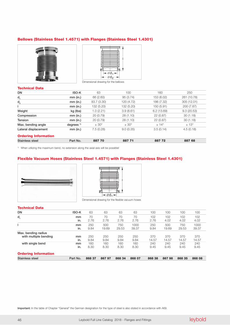
Technical DataDN ISO-K
d1 mm (in.)
d2 mm (in.)
l mm (in.)
Weight kg (lbs)
Compression mm (in.)
Tension mm (in.)
Max. bending angle degrees 1)
Lateral displacement mm (in.)
Ordering InformationStainless steel Part No.
1) When utilizing the maximum bend, no extension along the axial axis will be possible!
63 100 160 250
66 (2 .60) 95 (3 .74) 153 (6 .02) 261 (10 .78)
83 .7 (3 .30) 120 (4 .72) 186 (7 .32) 305 (12 .01)
132 (5 .20) 132 (5 .20) 150 (5 .91) 200 (7 .87)
1 .0 (2 .21) 3 .9 (8 .61) 6 .2 (13 .69) 9 .3 (20 .53)
20 (0 .79) 28 (1 .10) 22 (0 .87) 30 (1 .18)
20 (0 .79) 28 (1 .10) 22 (0 .87) 30 (1 .18)
± 30° ± 30° ± 14° ± 13°
7 .5 (0 .28) 9 .0 (0 .35) 3 .5 (0 .14) 4 .5 (0 .18)
887 70 887 71 887 72 887 68
Bellows (Stainless Steel 1.4571) with Flanges (Stainless Steel 1.4301)
d1
l
Technical DataDN ISO-K
d1 mm in.
l mm in.
Max. bending radius with multiple bending mm in. with single bend mm in.
Ordering InformationStainless steel Part No.
63 63 63 63 100 100 100 100
70 70 70 70 102 102 102 102 2 .76 2 .76 2 .76 2 .76 2 .76 4 .02 4 .02 4 .02
250 500 750 1000 250 500 750 1000 9 .84 19 .69 29 .53 39 .37 9 .84 19 .69 29 .53 39 .37
250 250 250 250 370 370 370 370 9 .84 9 .84 9 .84 9 .84 14 .57 14 .57 14 .57 14 .57 160 160 160 160 240 240 240 240 8 .30 8 .30 8 .30 8 .30 9 .45 9 .45 9 .45 9 .45
868 37 867 97 868 34 868 07 868 38 867 98 868 35 868 08
Flexible Vacuum Hoses (Stainless Steel 1.4571) with Flanges (Stainless Steel 1.4301)
Dimensional drawing for the flexible vacuum hoses
d1
l
d2Dimensional drawing for the bellows
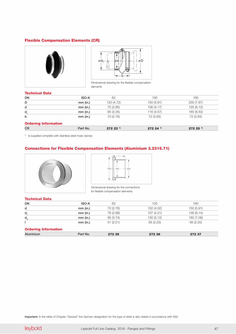
Important: In the table of Chapter “General” the German designation for the type of steel is also stated in accordance with AISI.
leyboldLeybold Full Line Catalog 2018 - Flanges and Fittings46 leybold Leybold Full Line Catalog 2018 - Flanges and Fittings 47
b
dd1 D
Technical DataDN ISO-K
D mm (in.)
d mm (in.)
d1 mm (in.)
b mm (in.)
Ordering InformationCR Part No.
1) Is supplied complete with stainless steel hose clamps
63 100 160
120 (4 .72) 150 (5 .91) 200 (7 .87)
75 (2 .95) 106 (4 .17) 155 (6 .10)
85 (3 .35) 116 (4 .57) 165 (6 .50)
70 (2 .76) 72 (2 .83) 72 (2 .83)
272 23 1) 272 24 1) 272 25 1)
Flexible Compensation Elements (CR)
Dimensional drawing for the flexible compensation elements
d
l
1d2 d
Technical DataDN ISO-K
d mm (in.)
d1 mm (in.)
d2 mm (in.)
l mm (in.)
Ordering InformationAluminium Part No.
63 100 160
70 (2 .76) 102 (4 .02) 150 (5 .91)
76 (2 .99) 107 (4 .21) 156 (6 .14)
95 (3 .74) 130 (5 .12) 180 (7 .09)
51 (2 .01) 56 (2 .20) 56 (2 .20)
272 35 272 36 272 37
Connections for Flexible Compensation Elements (Aluminium 3.2315.71)
Dimensional drawing for the connections for flexible compensation elements
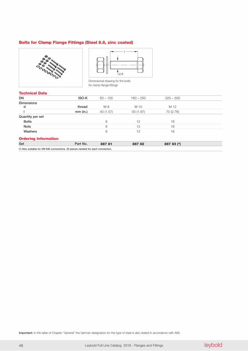
Important: In the table of Chapter “General” the German designation for the type of steel is also stated in accordance with AISI.
leyboldLeybold Full Line Catalog 2018 - Flanges and Fittings48
l
d
Technical DataDN ISO-K
Dimensions d thread
l mm (in.)
Quantity per set
Bolts
Nuts
Washers
Ordering InformationSet Part No.
(*) Also suitable for DN 630 connections. 20 pieces needed for each connection.
63 – 100 160 – 250 320 – 500
M 8 M 10 M 12
40 (1 .57) 50 (1 .97) 70 (2 .76)
8 12 16
8 12 16
8 12 16
887 81 887 82 887 83 (*)
Bolts for Clamp Flange Fittings (Steel 8.8, zinc coated)
Dimensional drawing for the bolts for clamp flange fittings
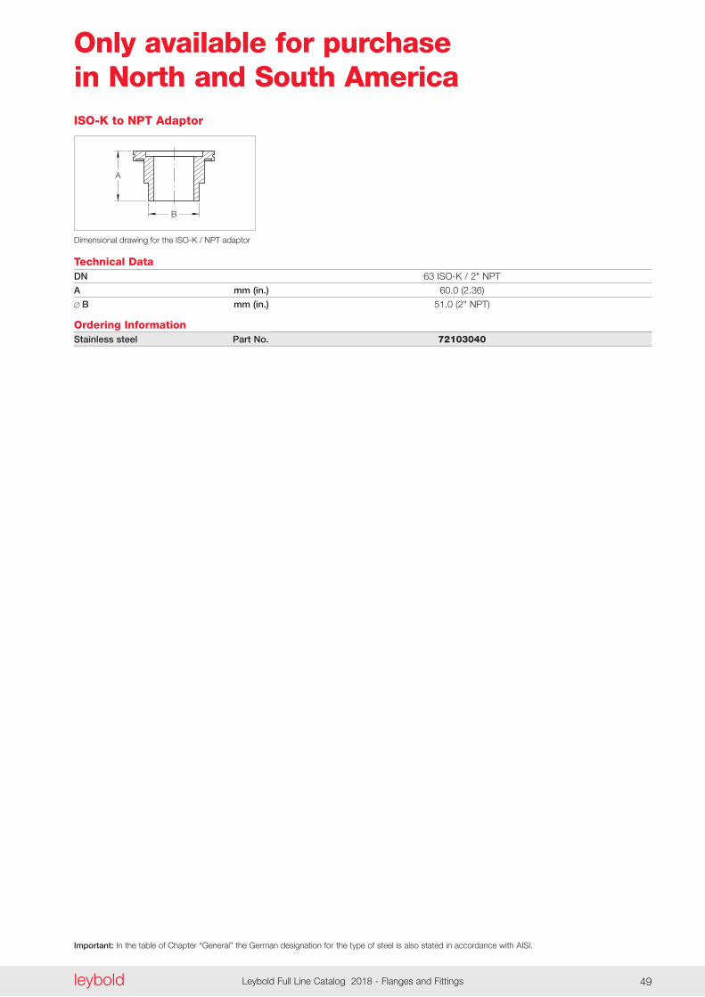
Important: In the table of Chapter “General” the German designation for the type of steel is also stated in accordance with AISI.
leyboldLeybold Full Line Catalog 2018 - Flanges and Fittings48 leybold Leybold Full Line Catalog 2018 - Flanges and Fittings 49
A
B
Technical Data
Dimensional drawing for the ISO-K / NPT adaptor
DN
A mm (in.)
B mm (in.)
Ordering InformationStainless steel Part No.
ISO-K to NPT Adaptor
63 ISO-K / 2" NPT
60 .0 (2 .36)
51 .0 (2" NPT)
72103040
Only available for purchase in North and South America
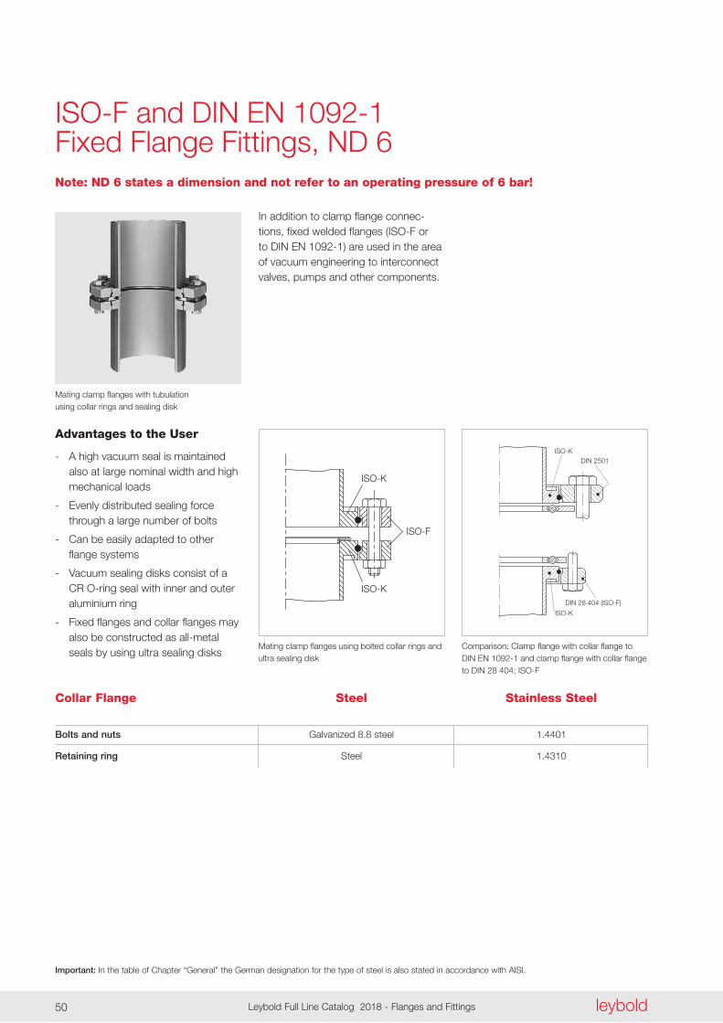
Important: In the table of Chapter “General” the German designation for the type of steel is also stated in accordance with AISI.
leyboldLeybold Full Line Catalog 2018 - Flanges and Fittings50
ISO-K
ISO-K
ISO-F
ISO-KDIN 2501
DIN 28 404 (ISO-F)
ISO-K
ISO-F and DIN EN 1092-1Fixed Flange Fittings, ND 6
Advantages to the User
- A high vacuum seal is maintained also at large nominal width and high mechanical loads
- Evenly distributed sealing force through a large number of bolts
- Can be easily adapted to other flange systems
- Vacuum sealing disks consist of a CR O-ring seal with inner and outer aluminium ring
- Fixed flanges and collar flanges may also be constructed as all-metal seals by using ultra sealing disks
In addition to clamp flange connec-tions, fixed welded flanges (ISO-F or to DIN EN 1092-1) are used in the area of vacuum engineering to interconnect valves, pumps and other components .
Mating clamp flanges with tubulation using collar rings and sealing disk
Mating clamp flanges using bolted collar rings andultra sealing disk
Comparison: Clamp flange with collar flange to DIN EN 1092-1 and clamp flange with collar flange to DIN 28 404; ISO-F
Collar Flange
Bolts and nuts
Retaining ring
Galvanized 8 .8 steel 1 .4401
Steel 1 .4310
Steel Stainless Steel
Note: ND 6 states a dimension and not refer to an operating pressure of 6 bar!
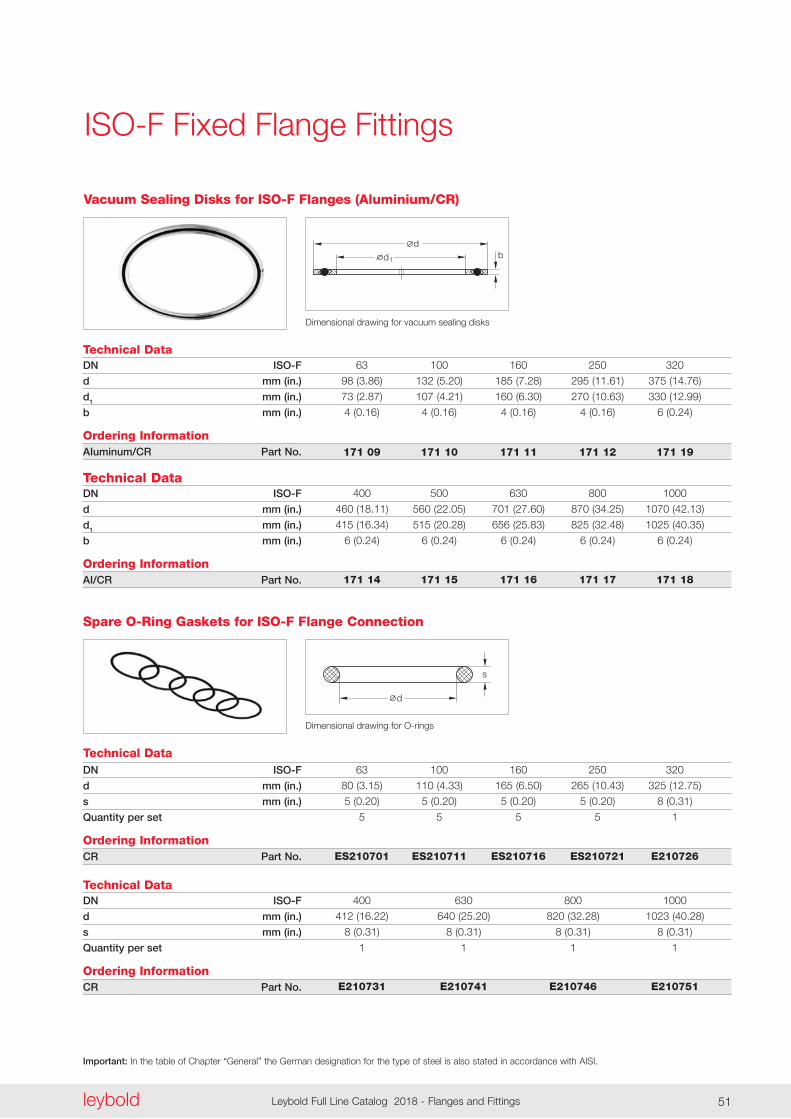
Important: In the table of Chapter “General” the German designation for the type of steel is also stated in accordance with AISI.
leyboldLeybold Full Line Catalog 2018 - Flanges and Fittings50 leybold Leybold Full Line Catalog 2018 - Flanges and Fittings 51
bd
d1
Dimensional drawing for vacuum sealing disks
ISO-F Fixed Flange Fittings
Technical DataDN ISO-F
d mm (in.)
d1 mm (in.)
b mm (in.)
Ordering InformationAIuminum/CR Part No.
63 100 160 250 320
98 (3 .86) 132 (5 .20) 185 (7 .28) 295 (11 .61) 375 (14 .76)
73 (2 .87) 107 (4 .21) 160 (6 .30) 270 (10 .63) 330 (12 .99)
4 (0 .16) 4 (0 .16) 4 (0 .16) 4 (0 .16) 6 (0 .24)
171 09 171 10 171 11 171 12 171 19
Vacuum Sealing Disks for ISO-F Flanges (Aluminium/CR)
Technical DataDN ISO-F
d mm (in.)
d1 mm (in.)
b mm (in.)
Ordering InformationAI/CR Part No.
400 500 630 800 1000
460 (18 .11) 560 (22 .05) 701 (27 .60) 870 (34 .25) 1070 (42 .13)
415 (16 .34) 515 (20 .28) 656 (25 .83) 825 (32 .48) 1025 (40 .35)
6 (0 .24) 6 (0 .24) 6 (0 .24) 6 (0 .24) 6 (0 .24)
171 14 171 15 171 16 171 17 171 18
d
s
Dimensional drawing for O-rings
Technical DataDN ISO-F
d mm (in.)
s mm (in.)
Quantity per set
Ordering InformationCR Part No.
63 100 160 250 320
80 (3 .15) 110 (4 .33) 165 (6 .50) 265 (10 .43) 325 (12 .75)
5 (0 .20) 5 (0 .20) 5 (0 .20) 5 (0 .20) 8 (0 .31)
5 5 5 5 1
ES210701 ES210711 ES210716 ES210721 E210726
Spare O-Ring Gaskets for ISO-F Flange Connection
Technical DataDN ISO-F
d mm (in.)
s mm (in.)
Quantity per set
Ordering InformationCR Part No.
400 630 800 1000
412 (16 .22) 640 (25 .20) 820 (32 .28) 1023 (40 .28)
8 (0 .31) 8 (0 .31) 8 (0 .31) 8 (0 .31)
1 1 1 1
E210731 E210741 E210746 E210751
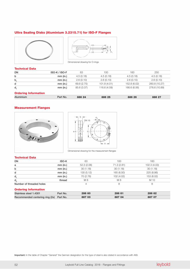
Important: In the table of Chapter “General” the German designation for the type of steel is also stated in accordance with AISI.
leyboldLeybold Full Line Catalog 2018 - Flanges and Fittings52
d
1d
bb 1
Ultra Sealing Disks (Aluminium 3.2315.71) for ISO-F Flanges
Dimensional drawing for O-rings
Technical DataDN ISO-K / ISO-F
b mm (in.)
b1 mm (in.)
d mm (in.)
d1 mm (in.)
Ordering InformationAluminium Part No.
63 100 160 250
4 .5 (0 .18) 4 .5 (0 .18) 4 .5 (0 .18) 4 .5 (0 .18)
2 .6 (0 .10) 2 .6 (0 .10) 2 .6 (0 .10) 2 .6 (0 .10)
69 .8 (2 .75) 101 .8 (4 .01) 152 .8 (6 .02) 260 .8 (10 .27)
85 .6 (3 .37) 116 .6 (4 .59) 166 .6 (6 .56) 276 .6 (10 .89)
886 24 886 25 886 26 886 27
Dimensional drawing for the measurement flanges
a
DN 16
b
ø d
d 2
1d
Technical DataDN ISO-K
a mm (in.)
b mm (in.)
d mm (in.)
d1 mm (in.)
d2 thread
Number of threaded holes
Ordering InformationStainless steel 1.4301 Part No.
Recommended centering ring (2x) Part No.
63 100 160
52 .3 (2 .06) 71 .3 (2 .81) 102 .3 (4 .03)
30 (1 .18) 30 (1 .18) 30 (1 .18)
130 (5 .12) 165 (6 .50) 225 (8 .86)
70 (2 .76) 102 (4 .02) 153 (6 .02)
M 8 M 8 M 10
4 8 8
286 60 286 61 286 62 887 03 887 04 887 07
Measurement Flanges
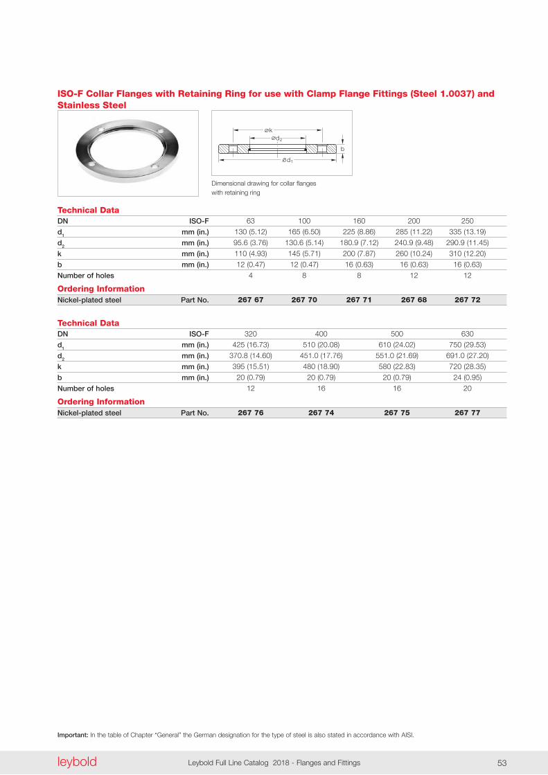
Important: In the table of Chapter “General” the German designation for the type of steel is also stated in accordance with AISI.
leyboldLeybold Full Line Catalog 2018 - Flanges and Fittings52 leybold Leybold Full Line Catalog 2018 - Flanges and Fittings 53
Technical DataDN ISO-F
d1 mm (in.)
d2 mm (in.)
k mm (in.)
b mm (in.)
Number of holes
Ordering InformationNickel-plated steel Part No.
63 100 160 200 250
130 (5 .12) 165 (6 .50) 225 (8 .86) 285 (11 .22) 335 (13 .19)
95 .6 (3 .76) 130 .6 (5 .14) 180 .9 (7 .12) 240 .9 (9 .48) 290 .9 (11 .45)
110 (4 .93) 145 (5 .71) 200 (7 .87) 260 (10 .24) 310 (12 .20)
12 (0 .47) 12 (0 .47) 16 (0 .63) 16 (0 .63) 16 (0 .63)
4 8 8 12 12
267 67 267 70 267 71 267 68 267 72
ISO-F Collar Flanges with Retaining Ring for use with Clamp Flange Fittings (Steel 1.0037) and Stainless Steel
Technical DataDN ISO-F
d1 mm (in.)
d2 mm (in.)
k mm (in.)
b mm (in.)
Number of holes
Ordering InformationNickel-plated steel Part No.
320 400 500 630
425 (16 .73) 510 (20 .08) 610 (24 .02) 750 (29 .53)
370 .8 (14 .60) 451 .0 (17 .76) 551 .0 (21 .69) 691 .0 (27 .20)
395 (15 .51) 480 (18 .90) 580 (22 .83) 720 (28 .35)
20 (0 .79) 20 (0 .79) 20 (0 .79) 24 (0 .95)
12 16 16 20
267 76 267 74 267 75 267 77
d2
k
b
d1
Dimensional drawing for collar flanges with retaining ring
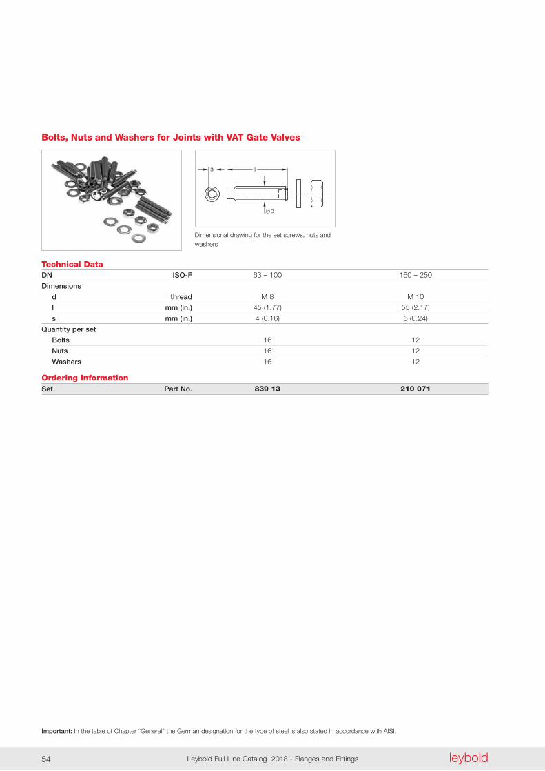
Important: In the table of Chapter “General” the German designation for the type of steel is also stated in accordance with AISI.
leyboldLeybold Full Line Catalog 2018 - Flanges and Fittings54
Bolts, Nuts and Washers for Joints with VAT Gate Valves
Technical DataDN ISO-F
Dimensions
d thread
l mm (in.)
s mm (in.)
Quantity per set
Bolts
Nuts
Washers
Ordering InformationSet Part No.
63 – 100 160 – 250
M 8 M 10
45 (1 .77) 55 (2 .17)
4 (0 .16) 6 (0 .24)
16 12
16 12
16 12
839 13 210 071
d
ls
Dimensional drawing for the set screws, nuts and washers
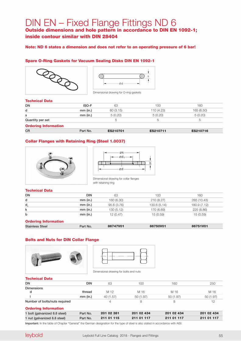
Important: In the table of Chapter “General” the German designation for the type of steel is also stated in accordance with AISI.
leyboldLeybold Full Line Catalog 2018 - Flanges and Fittings54 leybold Leybold Full Line Catalog 2018 - Flanges and Fittings 55
DIN EN – Fixed Flange Fittings ND 6
Note: ND 6 states a dimension and does not refer to an operating pressure of 6 bar!
Collar Flanges with Retaining Ring (Steel 1.0037)
Technical DataDN DIN
d mm (in.)
d1 mm (in.)
k mm (in.)
b mm (in.)
Ordering InformationStainless Steel Part No.
63 100 160
160 (6 .30) 210 (8 .27) 265 (10 .43)
95 .6 (3 .76) 130 .6 (5 .14) 180 .9 (7 .12)
130 (5 .12) 170 (6 .69) 225 (8 .86)
12 (0 .47) 15 (0 .59) 15 (0 .59)
86747V01 86750V01 86751V01
Technical DataDN ISO-F
d mm (in.)
s mm (in.)
Quantity per set
Ordering InformationCR Part No.
63 100 160
80 (3 .15) 110 (4 .23) 165 (6 .50)
5 (0 .20) 5 (0 .20) 5 (0 .20)
5 5 5
ES210701 ES210711 ES210716
Spare O-Ring Gaskets for Vacuum Sealing Disks DIN EN 1092-1
d
s
Dimensional drawing for O-ring gaskets
1
b
dk
d
Dimensional drawing for collar flanges with retaining ring
Bolts and Nuts for DIN Collar Flange
Dimensional drawing for bolts and nuts
Technical DataDN DIN
Dimensions d thread
l mm (in.)
Number of bolts/nuts required
Ordering Information1 bolt (galvanized 8.8 steel) Part No.
1 nut (galvanized 8.8 steel) Part No.
63 100 160 250
M 12 M 16 M 16 M 16
40 (1 .57) 50 (1 .97) 50 (1 .97) 50 (1 .97)
4 8 8 12
201 02 381 201 02 434 201 02 434 201 02 434 211 01 115 211 01 117 211 01 117 211 01 117
Outside dimensions and hole pattern in accordance to DIN EN 1092-1; inside contour similar with DIN 28404
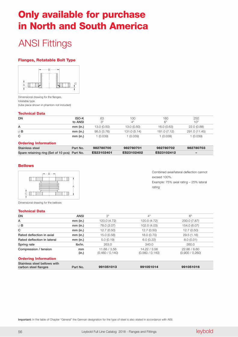
Important: In the table of Chapter “General” the German designation for the type of steel is also stated in accordance with AISI.
leyboldLeybold Full Line Catalog 2018 - Flanges and Fittings56
Only available for purchase in North and South America
A
B
C
Technical Data
Dimensional drawing for the flanges, rotatable type(tube piece shown in phantom not included)
DN ISO-K to ANSI
A mm (in.)
B mm (in.)
C mm (in.)
Ordering InformationStainless steel Part No.
Spare retaining ring (Set of 10 pcs) Part No.
Flanges, Rotatable Bolt Type
63 100 160 250 3" 4" 6" 10"
13 .0 (0 .50) 13 .0 (0 .50) 16 .0 (0 .63) 22 .0 (0 .88)
95 .5 (3 .76) 131 .0 (5 .14) 181 .0 (7 .12) 291 .0 (11 .45)
1 (0 .039) 1 (0 .039) 1 (0 .039) 1 (0 .039)
982780700 982780701 982780702 982780703 ES23102401 ES23102402 ES23102412 –
ANSI Fittings
C
B
A
Technical Data
Dimensional drawing for the bellows
DN ANSI
A mm (in.)
B mm (in.)
C mm (in.)
Rated deflection in axial mm (in.)
Rated deflection in lateral mm (in.)
Spring rate lbf/in.
Compression / tension mm (in.)
Ordering InformationStainless steel bellows with carbon steel flanges Part No.
Bellows
3" 4" 6"
120 .0 (4 .72) 120 .0 (4 .72) 200 .0 (7 .87)
78 .0 (3 .07) 102 .0 (4 .03) 154 .0 (6 .07)
12 .7 (0 .50) 12 .7 (0 .50) 12 .7 (0 .50)
15 .0 (0 .58) 18 .0 (0 .70) 29 .5 (1 .16)
5 .0 (0 .19) 6 .0 (0 .22) 8 .0 (0 .31)
263 .0 340 .0 260 .0
11 .68 / 3 .56 14 .22 / 3 .56 22 .86 / 6 .60 (0 .460 / 0 .140) (0 .560 / 0 .140) (0 .900 / 0 .260)
991051013 991051014 991051016
Combined axial/lateral deflection cannot
exceed 100% .
Example: 75% axial rating – 25% lateral
rating
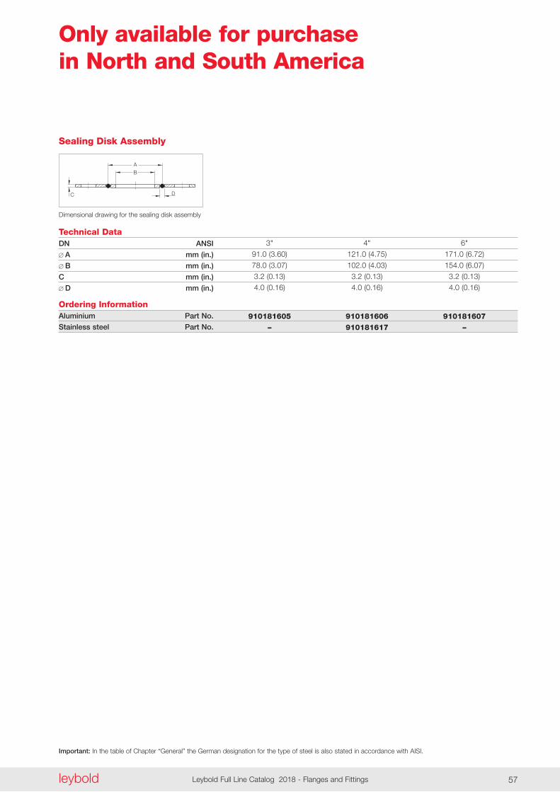
Important: In the table of Chapter “General” the German designation for the type of steel is also stated in accordance with AISI.
leyboldLeybold Full Line Catalog 2018 - Flanges and Fittings56 leybold Leybold Full Line Catalog 2018 - Flanges and Fittings 57
Only available for purchase in North and South America
D
B
A
C
Technical Data
Dimensional drawing for the sealing disk assembly
DN ANSI
A mm (in.)
B mm (in.)
C mm (in.)
D mm (in.)
Ordering InformationAluminium Part No.
Stainless steel Part No.
Sealing Disk Assembly
3" 4" 6"
91 .0 (3 .60) 121 .0 (4 .75) 171 .0 (6 .72)
78 .0 (3 .07) 102 .0 (4 .03) 154 .0 (6 .07)
3 .2 (0 .13) 3 .2 (0 .13) 3 .2 (0 .13)
4 .0 (0 .16) 4 .0 (0 .16) 4 .0 (0 .16)
910181605 910181606 910181607 – 910181617 –
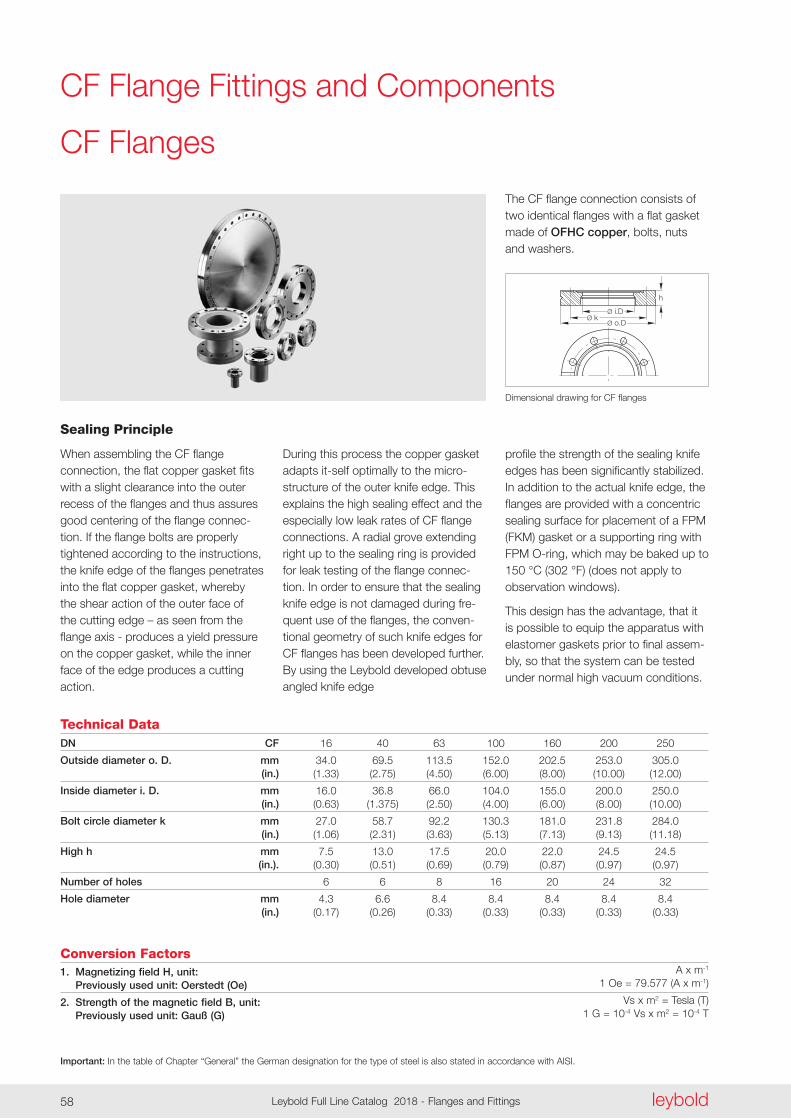
Important: In the table of Chapter “General” the German designation for the type of steel is also stated in accordance with AISI.
leyboldLeybold Full Line Catalog 2018 - Flanges and Fittings58
h
Ø i.D
Ø o.DØ k
The CF flange connection consists of two identical flanges with a flat gasket made of OFHC copper, bolts, nuts and washers .
CF Flanges
During this process the copper gasket adapts it-self optimally to the micro-structure of the outer knife edge . This explains the high sealing effect and the especially low leak rates of CF flange connections . A radial grove extending right up to the sealing ring is provided for leak testing of the flange connec-tion . In order to ensure that the sealing knife edge is not damaged during fre-quent use of the flanges, the conven-tional geometry of such knife edges for CF flanges has been developed further . By using the Leybold developed obtuse angled knife edge
Sealing Principle
When assembling the CF flange connection, the flat copper gasket fits with a slight clearance into the outer recess of the flanges and thus assures good centering of the flange connec-tion . If the flange bolts are properly tightened according to the instructions, the knife edge of the flanges penetrates into the flat copper gasket, whereby the shear action of the outer face of the cutting edge – as seen from the flange axis - produces a yield pressure on the copper gasket, while the inner face of the edge produces a cutting action .
profile the strength of the sealing knife edges has been significantly stabilized . In addition to the actual knife edge, the flanges are provided with a con centric sealing surface for placement of a FPM (FKM) gasket or a supporting ring with FPM O-ring, which may be baked up to 150 °C (302 °F) (does not apply to observation windows) .
This design has the advantage, that it is possible to equip the apparatus with elastomer gaskets prior to final assem-bly, so that the system can be tested under normal high vacuum conditions .
Technical DataDN CF
Outside diameter o. D. mm (in.)
Inside diameter i. D. mm (in.)
Bolt circle diameter k mm (in.)
High h mm (in.).
Number of holes
Hole diameter mm (in.)
16 40 63 100 160 200 250
34 .0 69 .5 113 .5 152 .0 202 .5 253 .0 305 .0 (1 .33) (2 .75) (4 .50) (6 .00) (8 .00) (10 .00) (12 .00)
16 .0 36 .8 66 .0 104 .0 155 .0 200 .0 250 .0 (0 .63) (1 .375) (2 .50) (4 .00) (6 .00) (8 .00) (10 .00)
27 .0 58 .7 92 .2 130 .3 181 .0 231 .8 284 .0 (1 .06) (2 .31) (3 .63) (5 .13) (7 .13) (9 .13) (11 .18)
7 .5 13 .0 17 .5 20 .0 22 .0 24 .5 24 .5 (0 .30) (0 .51) (0 .69) (0 .79) (0 .87) (0 .97) (0 .97)
6 6 8 16 20 24 32
4 .3 6 .6 8 .4 8 .4 8 .4 8 .4 8 .4 (0 .17) (0 .26) (0 .33) (0 .33) (0 .33) (0 .33) (0 .33)
Conversion Factors1. Magnetizing field H, unit: Previously used unit: Oerstedt (Oe)
2. Strength of the magnetic field B, unit: Previously used unit: Gauß (G)
A x m-1 1 Oe = 79 .577 (A x m-1)
Vs x m2 = Tesla (T) 1 G = 10-4 Vs x m2 = 10-4 T
Dimensional drawing for CF flanges
CF Flange Fittings and Components
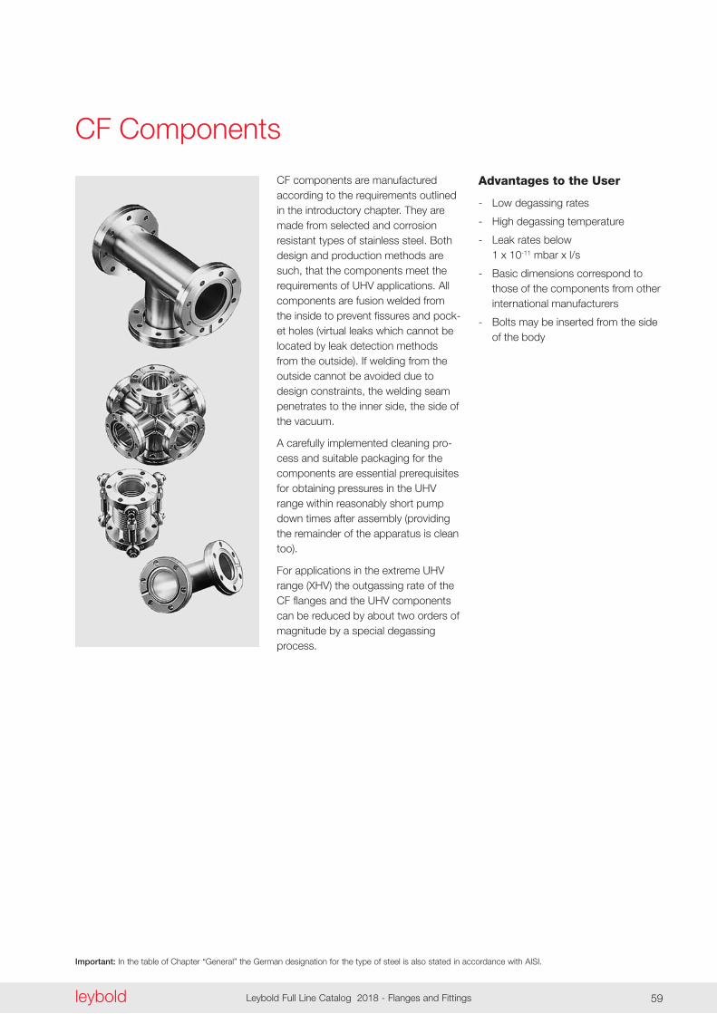
Important: In the table of Chapter “General” the German designation for the type of steel is also stated in accordance with AISI.
leyboldLeybold Full Line Catalog 2018 - Flanges and Fittings58 leybold Leybold Full Line Catalog 2018 - Flanges and Fittings 59
CF Components
CF components are manufactured according to the requirements outlined in the introductory chapter . They are made from selected and corrosion resistant types of stainless steel . Both design and production methods are such, that the components meet the requirements of UHV applications . All components are fusion welded from the inside to prevent fissures and pock-et holes (virtual leaks which cannot be located by leak detection methods from the outside) . If welding from the outside cannot be avoided due to design constraints, the welding seam penetrates to the inner side, the side of the vacuum .
A carefully implemented cleaning pro-cess and suitable packaging for the components are essential prerequisites for obtaining pressures in the UHV range within reasonably short pump down times after assembly (providing the remainder of the apparatus is clean too) .
For applications in the extreme UHV range (XHV) the outgassing rate of the CF flanges and the UHV components can be reduced by about two orders of magnitude by a special degassing process .
Advantages to the User
- Low degassing rates
- High degassing temperature
- Leak rates below 1 x 10-11 mbar x l/s
- Basic dimensions correspond to those of the components from other international manufacturers
- Bolts may be inserted from the side of the body

Important: In the table of Chapter “General” the German designation for the type of steel is also stated in accordance with AISI.
leyboldLeybold Full Line Catalog 2018 - Flanges and Fittings60
1
d
d
h
Dimensional drawing for the copper gaskets for CF flanges
Technical DataDN CF
Outside diameter in.
d mm (in.)
d1 mm (in.)
Set of 5
Set of 10
Ordering InformationQuality: Standard Part No.
Copper Gaskets for CF Flanges (OFHC Copper – Oxygen-Free)
16 40 63 100 160 200 250
1 .33 2 .75 4 .50 6 .00 8 .00 10 .00 12 .00
16 .2 39 .0 63 .6 101 .8 152 .6 203 .4 254 .0 (0 .64) (1 .54) (2 .50) (4 .01) (6 .01) (8 .01) (10 .00)
21 .3 48 .1 82 .4 120 .5 171 .3 222 .1 272 .7 (0 .84) (1 .89) (3 .24) (4 .74) (6 .74) (8 .74) (10 .74)
– – – – – – x
x x x x x x –
ES83941 ES83943 ES83944 ES83945 ES83946 ES83947 ES83948
d
d
DN 16 CF DN 40 CF
DN 63 - 200 CF
Dimensional drawing for the profiled gaskets without support ring
Technical DataDN CF
Outside diameter in.
d mm (in.)
Bakeout temperature °C (°F)
Set of 2
Set of 5
Ordering Information Part No.
FPM (FKM) Profiled Gasket without Support Ring
16 40 63 100 160 200
1 .33 2 .75 4 .50 6 .00 8 .00 10 .00
16 .0 (0 .63) 42 .0 (1 .65) 69 .7 (2 .74) 107 .8 (4 .24) 156 .0 (6 .14) 206 .0 (8 .11)
160 (320) 160 (320) 160 (320) 160 (320) 160 (320) 160 (320)
– – x x x x
x x – – – –
ES83921 ES83923 ES83934 ES83935 ES83936 ES83937
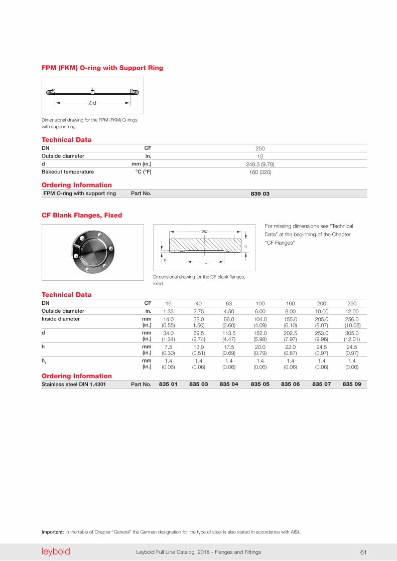
Important: In the table of Chapter “General” the German designation for the type of steel is also stated in accordance with AISI.
leyboldLeybold Full Line Catalog 2018 - Flanges and Fittings60 leybold Leybold Full Line Catalog 2018 - Flanges and Fittings 61
d
Technical Data
Dimensional drawing for the FPM (FKM) O-rings with support ring
DN CF
Outside diameter in.
d mm (in.)
Bakeout temperature °C (°F)
Ordering Information FPM O-ring with support ring Part No.
FPM (FKM) O-ring with Support Ring
250
12
248 .3 (9 .78)
160 (320)
839 03
h
i.D
dd
h1
Technical Data
Dimensional drawing for the CF blank flanges, fixed
DN CF
Outside diameter in.
Inside diameter mm (in.)
d mm (in.)
h mm (in.)
h1 mm (in.)
Ordering InformationStainless steel DIN 1.4301 Part No.
CF Blank Flanges, Fixed
16 40 63 100 160 200 250
1 .33 2 .75 4 .50 6 .00 8 .00 10 .00 12 .00
14 .0 38 .0 66 .0 104 .0 155 .0 205 .0 256 .0 (0 .55) 1 .50) (2 .60) (4 .09) (6 .10) (8 .07) (10 .08)
34 .0 69 .5 113 .5 152 .0 202 .5 253 .0 305 .0 (1 .34) (2 .74) (4 .47) (5 .98) (7 .97) (9 .96) (12 .01)
7 .5 13 .0 17 .5 20 .0 22 .0 24 .5 24 .5 (0 .30) (0 .51) (0 .69) (0 .79) (0 .87) (0 .97) (0 .97)
1 .4 1 .4 1 .4 1 .4 1 .4 1 .4 1 .4 (0 .06) (0 .06) (0 .06) (0 .06) (0 .06) (0 .06) (0 .06)
835 01 835 03 835 04 835 05 835 06 835 07 835 09
For missing dimensions see “Technical
Data” at the beginning of the Chapter
“CF Flanges”
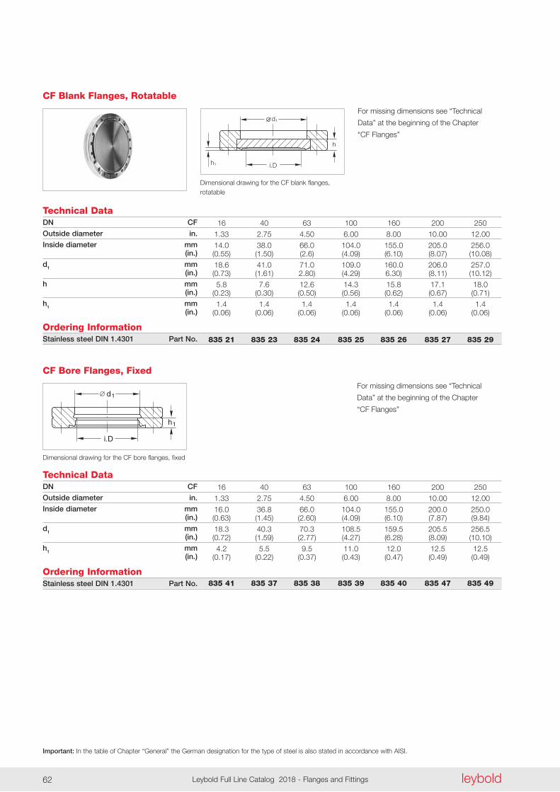
Important: In the table of Chapter “General” the German designation for the type of steel is also stated in accordance with AISI.
leyboldLeybold Full Line Catalog 2018 - Flanges and Fittings62
i.D
d1
h
h1
Technical Data
Dimensional drawing for the CF blank flanges, rotatable
DN CF
Outside diameter in.
Inside diameter mm (in.)
d1 mm (in.)
h mm (in.)
h1 mm (in.)
Ordering InformationStainless steel DIN 1.4301 Part No.
CF Blank Flanges, Rotatable
16 40 63 100 160 200 250
1 .33 2 .75 4 .50 6 .00 8 .00 10 .00 12 .00
14 .0 38 .0 66 .0 104 .0 155 .0 205 .0 256 .0 (0 .55) (1 .50) (2 .6) (4 .09) (6 .10) (8 .07) (10 .08)
18 .6 41 .0 71 .0 109 .0 160 .0 206 .0 257 .0 (0 .73) (1 .61) 2 .80) (4 .29) 6 .30) (8 .11) (10 .12)
5 .8 7 .6 12 .6 14 .3 15 .8 17 .1 18 .0 (0 .23) (0 .30) (0 .50) (0 .56) (0 .62) (0 .67) (0 .71)
1 .4 1 .4 1 .4 1 .4 1 .4 1 .4 1 .4 (0 .06) (0 .06) (0 .06) (0 .06) (0 .06) (0 .06) (0 .06)
835 21 835 23 835 24 835 25 835 26 835 27 835 29
i.D
d1
h1
Technical Data
Dimensional drawing for the CF bore flanges, fixed
DN CF
Outside diameter in.
Inside diameter mm (in.)
d1 mm (in.)
h1 mm (in.)
Ordering InformationStainless steel DIN 1.4301 Part No.
CF Bore Flanges, Fixed
16 40 63 100 160 200 250
1 .33 2 .75 4 .50 6 .00 8 .00 10 .00 12 .00
16 .0 36 .8 66 .0 104 .0 155 .0 200 .0 250 .0 (0 .63) (1 .45) (2 .60) (4 .09) (6 .10) (7 .87) (9 .84)
18 .3 40 .3 70 .3 108 .5 159 .5 205 .5 256 .5 (0 .72) (1 .59) (2 .77) (4 .27) (6 .28) (8 .09) (10 .10)
4 .2 5 .5 9 .5 11 .0 12 .0 12 .5 12 .5 (0 .17) (0 .22) (0 .37) (0 .43) (0 .47) (0 .49) (0 .49)
835 41 835 37 835 38 835 39 835 40 835 47 835 49
For missing dimensions see “Technical
Data” at the beginning of the Chapter
“CF Flanges”
For missing dimensions see “Technical
Data” at the beginning of the Chapter
“CF Flanges”
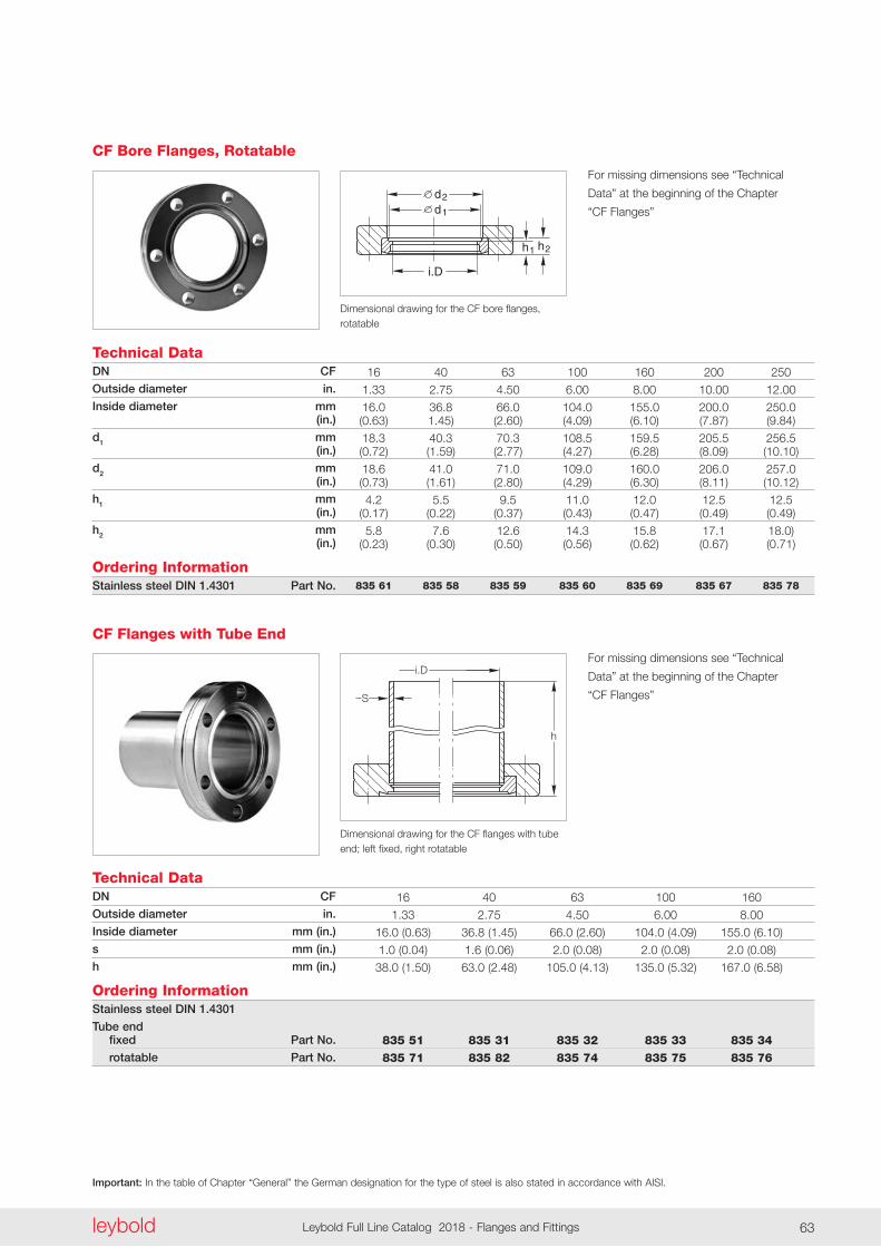
Important: In the table of Chapter “General” the German designation for the type of steel is also stated in accordance with AISI.
leyboldLeybold Full Line Catalog 2018 - Flanges and Fittings62 leybold Leybold Full Line Catalog 2018 - Flanges and Fittings 63
Technical DataDN CF
Outside diameter in.
Inside diameter mm (in.)
d1 mm (in.)
d2 mm (in.)
h1 mm (in.)
h2 mm (in.)
Ordering InformationStainless steel DIN 1.4301 Part No.
CF Bore Flanges, Rotatable
16 40 63 100 160 200 250
1 .33 2 .75 4 .50 6 .00 8 .00 10 .00 12 .00
16 .0 36 .8 66 .0 104 .0 155 .0 200 .0 250 .0 (0 .63) 1 .45) (2 .60) (4 .09) (6 .10) (7 .87) (9 .84)
18 .3 40 .3 70 .3 108 .5 159 .5 205 .5 256 .5 (0 .72) (1 .59) (2 .77) (4 .27) (6 .28) (8 .09) (10 .10)
18 .6 41 .0 71 .0 109 .0 160 .0 206 .0 257 .0 (0 .73) (1 .61) (2 .80) (4 .29) (6 .30) (8 .11) (10 .12)
4 .2 5 .5 9 .5 11 .0 12 .0 12 .5 12 .5 (0 .17) (0 .22) (0 .37) (0 .43) (0 .47) (0 .49) (0 .49)
5 .8 7 .6 12 .6 14 .3 15 .8 17 .1 18 .0) (0 .23) (0 .30) (0 .50) (0 .56) (0 .62) (0 .67) (0 .71)
835 61 835 58 835 59 835 60 835 69 835 67 835 78
i.D
d1
h1
d2
h2
Dimensional drawing for the CF bore flanges, rotatable
S
h
i.D
Dimensional drawing for the CF flanges with tube end; left fixed, right rotatable
Technical DataDN CF
Outside diameter in.
Inside diameter mm (in.)
s mm (in.)
h mm (in.)
Ordering InformationStainless steel DIN 1.4301
Tube end fixed Part No.
rotatable Part No.
CF Flanges with Tube End
16 40 63 100 160
1 .33 2 .75 4 .50 6 .00 8 .00
16 .0 (0 .63) 36 .8 (1 .45) 66 .0 (2 .60) 104 .0 (4 .09) 155 .0 (6 .10)
1 .0 (0 .04) 1 .6 (0 .06) 2 .0 (0 .08) 2 .0 (0 .08) 2 .0 (0 .08)
38 .0 (1 .50) 63 .0 (2 .48) 105 .0 (4 .13) 135 .0 (5 .32) 167 .0 (6 .58)
835 51 835 31 835 32 835 33 835 34 835 71 835 82 835 74 835 75 835 76
For missing dimensions see “Technical
Data” at the beginning of the Chapter
“CF Flanges”
For missing dimensions see “Technical
Data” at the beginning of the Chapter
“CF Flanges”
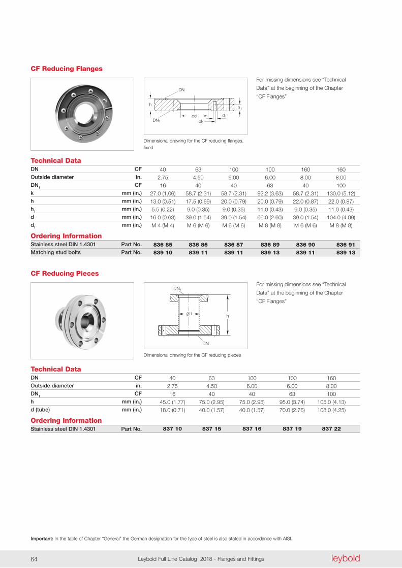
Important: In the table of Chapter “General” the German designation for the type of steel is also stated in accordance with AISI.
leyboldLeybold Full Line Catalog 2018 - Flanges and Fittings64
DN
DN1
ødøk
hh1
d1
Dimensional drawing for the CF reducing flanges, fixed
Technical DataDN CF
Outside diameter in.
DN1 CF
k mm (in.)
h mm (in.)
h1 mm (in.)
d mm (in.)
d1 mm (in.)
Ordering InformationStainless steel DIN 1.4301 Part No.
Matching stud bolts Part No.
CF Reducing Flanges
40 63 100 100 160 160
2 .75 4 .50 6 .00 6 .00 8 .00 8 .00
16 40 40 63 40 100
27 .0 (1 .06) 58 .7 (2 .31) 58 .7 (2 .31) 92 .2 (3 .63) 58 .7 (2 .31) 130 .0 (5 .12)
13 .0 (0 .51) 17 .5 (0 .69) 20 .0 (0 .79) 20 .0 (0 .79) 22 .0 (0 .87) 22 .0 (0 .87)
5 .5 (0 .22) 9 .0 (0 .35) 9 .0 (0 .35) 11 .0 (0 .43) 9 .0 (0 .35) 11 .0 (0 .43)
16 .0 (0 .63) 39 .0 (1 .54) 39 .0 (1 .54) 66 .0 (2 .60) 39 .0 (1 .54) 104 .0 (4 .09)
M 4 (M 4) M 6 (M 6) M 6 (M 6) M 8 (M 8) M 6 (M 6) M 8 (M 8)
836 85 836 86 836 87 836 89 836 90 836 91
839 10 839 11 839 11 839 13 839 11 839 13
DN
hd
DN1
Dimensional drawing for the CF reducing pieces
Technical DataDN CF
Outside diameter in.
DN1 CF
h mm (in.)
d (tube) mm (in.)
Ordering InformationStainless steel DIN 1.4301 Part No.
CF Reducing Pieces
40 63 100 100 160
2 .75 4 .50 6 .00 6 .00 8 .00
16 40 40 63 100
45 .0 (1 .77) 75 .0 (2 .95) 75 .0 (2 .95) 95 .0 (3 .74) 105 .0 (4 .13)
18 .0 (0 .71) 40 .0 (1 .57) 40 .0 (1 .57) 70 .0 (2 .76) 108 .0 (4 .25)
837 10 837 15 837 16 837 19 837 22
For missing dimensions see “Technical
Data” at the beginning of the Chapter
“CF Flanges”
For missing dimensions see “Technical
Data” at the beginning of the Chapter
“CF Flanges”
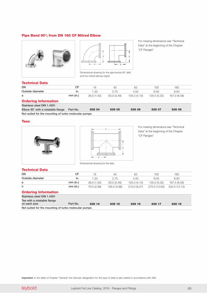
Important: In the table of Chapter “General” the German designation for the type of steel is also stated in accordance with AISI.
leyboldLeybold Full Line Catalog 2018 - Flanges and Fittings64 leybold Leybold Full Line Catalog 2018 - Flanges and Fittings 65
a
a a
a
Dimensional drawing for the pipe bends 90° (left) and the mitred elbows (right)
Technical DataDN CF
Outside diameter in.
a mm (in.)
Ordering InformationStainless steel DIN 1.4301
Elbow 90° with a rotatable flange Part No.
Not suited for the mounting of turbo molecular pumps
Pipe Bend 90°; from DN 160 CF Mitred Elbow
16 40 63 100 160
1 .33 2 .75 4 .50 6 .00 8 .00
38 .0 (1 .50) 63 .0 (2 .48) 105 .0 (4 .13) 135 .0 (5 .32) 167 .0 (6 .58)
836 04 836 05 836 06 836 07 836 08
a
a
h
Dimensional drawing for the tees
Technical DataDN CF
Outside diameter in.
a mm (in.)
h mm (in.)
Ordering InformationStainless steel DIN 1.4301
Tee with a rotatable flange on each axis Part No.
Not suited for the mounting of turbo molecular pumps
Tees
16 40 63 100 160
1 .33 2 .75 4 .50 6 .00 8 .00
38 .0 (1 .50) 63 .0 (2 .48) 105 .0 (4 .13) 135 .0 (5 .32) 167 .0 (6 .58)
76 .0 (2 .99) 126 .0 (4 .96) 210 .0 (8 .27) 270 .0 (10 .63) 334 .0 (13 .15)
836 14 836 15 836 16 836 17 836 18
For missing dimensions see “Technical
Data” at the beginning of the Chapter
“CF Flanges”
For missing dimensions see “Technical
Data” at the beginning of the Chapter
“CF Flanges”
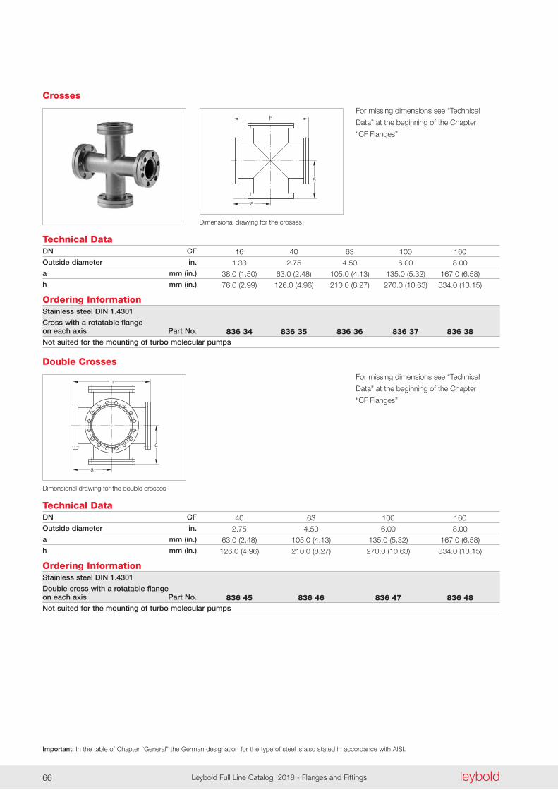
Important: In the table of Chapter “General” the German designation for the type of steel is also stated in accordance with AISI.
leyboldLeybold Full Line Catalog 2018 - Flanges and Fittings66
Crosses
a
a
h
Dimensional drawing for the crosses
Technical DataDN CF
Outside diameter in.
a mm (in.)
h mm (in.)
Ordering InformationStainless steel DIN 1.4301
Cross with a rotatable flange on each axis Part No.
Not suited for the mounting of turbo molecular pumps
16 40 63 100 160
1 .33 2 .75 4 .50 6 .00 8 .00
38 .0 (1 .50) 63 .0 (2 .48) 105 .0 (4 .13) 135 .0 (5 .32) 167 .0 (6 .58)
76 .0 (2 .99) 126 .0 (4 .96) 210 .0 (8 .27) 270 .0 (10 .63) 334 .0 (13 .15)
836 34 836 35 836 36 836 37 836 38
a
a
h
Technical Data
Dimensional drawing for the double crosses
DN CF
Outside diameter in.
a mm (in.)
h mm (in.)
Ordering InformationStainless steel DIN 1.4301
Double cross with a rotatable flange on each axis Part No.
Not suited for the mounting of turbo molecular pumps
Double Crosses
40 63 100 160
2 .75 4 .50 6 .00 8 .00
63 .0 (2 .48) 105 .0 (4 .13) 135 .0 (5 .32) 167 .0 (6 .58)
126 .0 (4 .96) 210 .0 (8 .27) 270 .0 (10 .63) 334 .0 (13 .15)
836 45 836 46 836 47 836 48
For missing dimensions see “Technical
Data” at the beginning of the Chapter
“CF Flanges”
For missing dimensions see “Technical
Data” at the beginning of the Chapter
“CF Flanges”
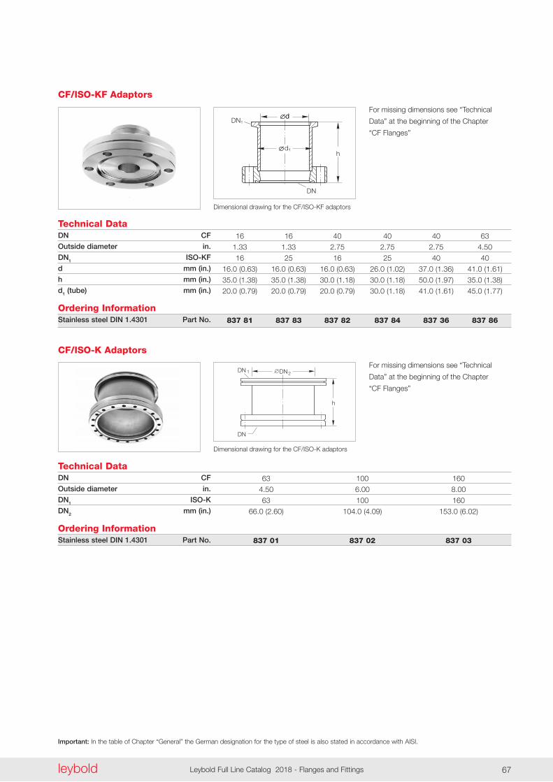
Important: In the table of Chapter “General” the German designation for the type of steel is also stated in accordance with AISI.
leyboldLeybold Full Line Catalog 2018 - Flanges and Fittings66 leybold Leybold Full Line Catalog 2018 - Flanges and Fittings 67
DN
hd1
ddDN1
Dimensional drawing for the CF/ISO-KF adaptors
Technical DataDN CF
Outside diameter in.
DN1 ISO-KF
d mm (in.)
h mm (in.)
d1 (tube) mm (in.)
Ordering InformationStainless steel DIN 1.4301 Part No.
CF/ISO-KF Adaptors
16 16 40 40 40 63
1 .33 1 .33 2 .75 2 .75 2 .75 4 .50
16 25 16 25 40 40
16 .0 (0 .63) 16 .0 (0 .63) 16 .0 (0 .63) 26 .0 (1 .02) 37 .0 (1 .36) 41 .0 (1 .61)
35 .0 (1 .38) 35 .0 (1 .38) 30 .0 (1 .18) 30 .0 (1 .18) 50 .0 (1 .97) 35 .0 (1 .38)
20 .0 (0 .79) 20 .0 (0 .79) 20 .0 (0 .79) 30 .0 (1 .18) 41 .0 (1 .61) 45 .0 (1 .77)
837 81 837 83 837 82 837 84 837 36 837 86
h
DN 1
DN
2DN
Technical Data
Dimensional drawing for the CF/ISO-K adaptors
DN CF
Outside diameter in.
DN1 ISO-K
DN2 mm (in.)
Ordering InformationStainless steel DIN 1.4301 Part No.
CF/ISO-K Adaptors
63 100 160
4 .50 6 .00 8 .00
63 100 160
66 .0 (2 .60) 104 .0 (4 .09) 153 .0 (6 .02)
837 01 837 02 837 03
For missing dimensions see “Technical
Data” at the beginning of the Chapter
“CF Flanges”
For missing dimensions see “Technical
Data” at the beginning of the Chapter
“CF Flanges”
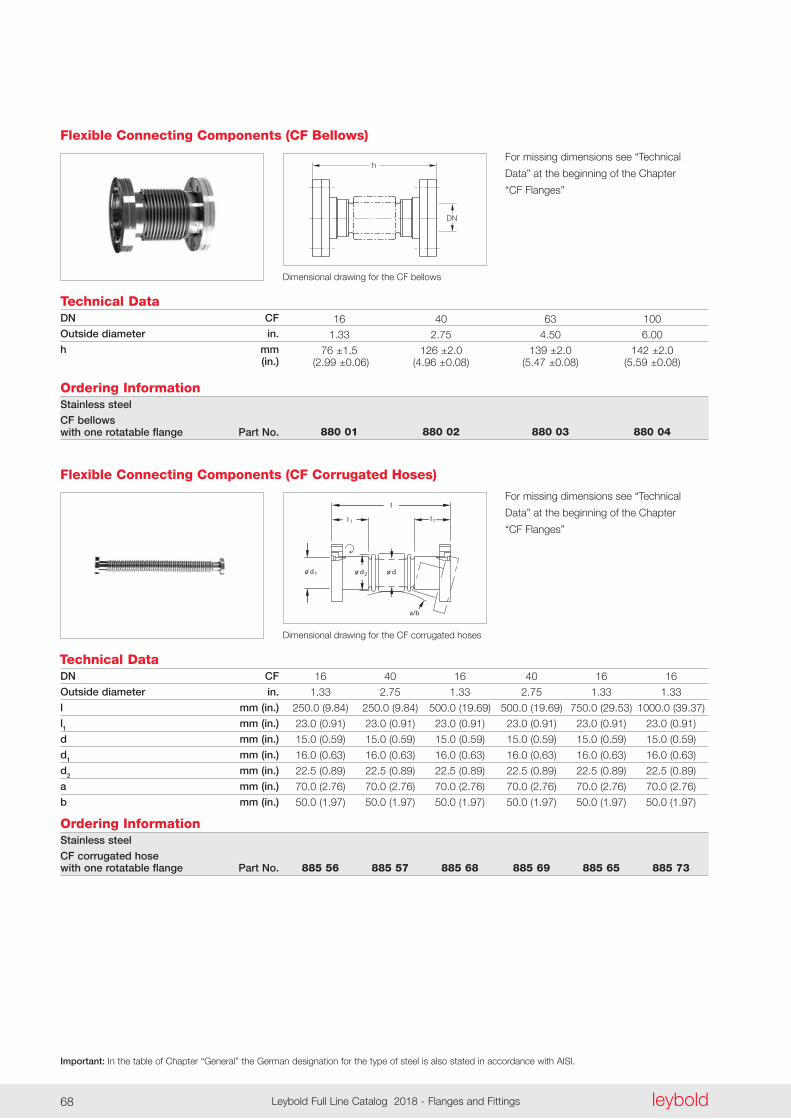
Important: In the table of Chapter “General” the German designation for the type of steel is also stated in accordance with AISI.
leyboldLeybold Full Line Catalog 2018 - Flanges and Fittings68
h
DN
Dimensional drawing for the CF bellows
Technical DataDN CF
Outside diameter in.
h mm (in.)
Ordering InformationStainless steel
CF bellows with one rotatable flange Part No.
Flexible Connecting Components (CF Bellows)
16 40 63 100
1 .33 2 .75 4 .50 6 .00
76 ±1 .5 126 ±2 .0 139 ±2 .0 142 ±2 .0 (2 .99 ±0 .06) (4 .96 ±0 .08) (5 .47 ±0 .08) (5 .59 ±0 .08)
880 01 880 02 880 03 880 04
Dimensional drawing for the CF corrugated hoses
o d o d o d
a/b
l
l1l 1
1 2
Technical DataDN CF
Outside diameter in.
l mm (in.)
l1 mm (in.)
d mm (in.)
d1 mm (in.)
d2 mm (in.)
a mm (in.)
b mm (in.)
Ordering InformationStainless steel
CF corrugated hose with one rotatable flange Part No.
Flexible Connecting Components (CF Corrugated Hoses)
16 40 16 40 16 16
1 .33 2 .75 1 .33 2 .75 1 .33 1 .33
250 .0 (9 .84) 250 .0 (9 .84) 500 .0 (19 .69) 500 .0 (19 .69) 750 .0 (29 .53) 1000 .0 (39 .37)
23 .0 (0 .91) 23 .0 (0 .91) 23 .0 (0 .91) 23 .0 (0 .91) 23 .0 (0 .91) 23 .0 (0 .91)
15 .0 (0 .59) 15 .0 (0 .59) 15 .0 (0 .59) 15 .0 (0 .59) 15 .0 (0 .59) 15 .0 (0 .59)
16 .0 (0 .63) 16 .0 (0 .63) 16 .0 (0 .63) 16 .0 (0 .63) 16 .0 (0 .63) 16 .0 (0 .63)
22 .5 (0 .89) 22 .5 (0 .89) 22 .5 (0 .89) 22 .5 (0 .89) 22 .5 (0 .89) 22 .5 (0 .89)
70 .0 (2 .76) 70 .0 (2 .76) 70 .0 (2 .76) 70 .0 (2 .76) 70 .0 (2 .76) 70 .0 (2 .76)
50 .0 (1 .97) 50 .0 (1 .97) 50 .0 (1 .97) 50 .0 (1 .97) 50 .0 (1 .97) 50 .0 (1 .97)
885 56 885 57 885 68 885 69 885 65 885 73
For missing dimensions see “Technical
Data” at the beginning of the Chapter
“CF Flanges”
For missing dimensions see “Technical
Data” at the beginning of the Chapter
“CF Flanges”
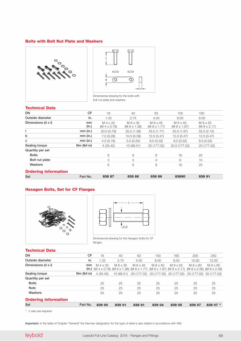
Important: In the table of Chapter “General” the German designation for the type of steel is also stated in accordance with AISI.
leyboldLeybold Full Line Catalog 2018 - Flanges and Fittings68 leybold Leybold Full Line Catalog 2018 - Flanges and Fittings 69
Dimensional drawing for the bolts with bolt nut plate and washers
Technical DataDN CF
Outside diameter in.
Dimensions (d x l) mm (in.)
l mm (in.)
b mm (in.)
c mm (in.)
Sealing torque Nm (lbf-in)
Quantity per set
Bolts
Bolt nut plate
Washers
Ordering informationSet Part No.
Bolts with Bolt Nut Plate and Washers
16 40 63 100 160
1 .33 2 .75 4 .50 6 .00 8 .00
M 4 x 20 M 6 x 35 M 8 x 45 M 8 x 50 M 8 x 55 (M 4 x 0 .79) (M 6 x 1 .38) (M 8 x 1 .77) (M 8 x 1 .97) (M 8 x 2 .17)
20 .0 (0 .79) 35 .0 (1 .38) 45 .0 (1 .77) 50 .0 (1 .97) 55 .0 (2 .15)
7 .0 (0 .28) 10 .0 (0 .39) 12 .0 (0 .47) 12 .0 (0 .47) 12 .0 (0 .47)
4 .0 (0 .16) 5 .0 (0 .20) 8 .0 (0 .32) 8 .0 (0 .32) 8 .0 (0 .32)
4 (35 .40) 10 (88 .51) 20 (177 .02) 20 .0 (177 .02) 20 (177 .02)
6 6 8 16 20
3 3 4 8 10
6 6 8 16 20
838 87 838 88 838 89 83890 838 91
Technical DataDN CF
Outside diameter in.
Dimensions (d x l) mm (in.)
Sealing torque Nm (lbf-in)
Quantity per set
Bolts
Nuts
Washers
Ordering informationSet Part No.
1) 2 sets are required
Hexagon Bolts, Set for CF Flanges
16 40 63 100 160 200 250
1 .33 2 .75 4 .50 6 .00 8 .00 10 .00 12 .00
M 4 x 20 M 6 x 35 M 8 x 45 M 8 x 50 M 8 x 55 M 8 x 60 M 8 x 60 (M 4 x 0 .79) (M 6 x 1 .38) (M 8 x 1 .77) (M 8 x 1 .97) (M 8 x 2 .17) (M 8 x 2 .36) (M 8 x 2 .36)
4 (35 .40) 10 (88 .51) 20 (177 .02) 20 (177 .02) 20 (177 .02) 20 (177 .02) 20 (177 .02)
25 25 25 25 25 25 25
25 25 25 25 25 25 25
25 25 25 25 25 25 25
839 00 839 01 838 81 839 04 839 05 839 07 839 07 1)
l
d
Dimensional drawing for the hexagon bolts for CF flanges
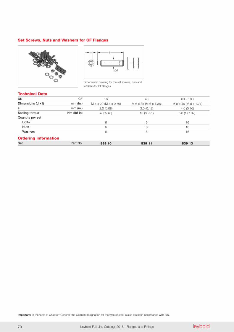
leyboldLeybold Full Line Catalog 2018 - Flanges and Fittings70
Important: In the table of Chapter “General” the German designation for the type of steel is also stated in accordance with AISI.
leyboldLeybold Full Line Catalog 2018 - Flanges and Fittings70
d
ls
Dimensional drawing for the set screws, nuts and washers for CF flanges
Technical DataDN CF
Dimensions (d x l) mm (in.)
s mm (in.)
Sealing torque Nm (lbf-in)
Quantity per set
Bolts
Nuts
Washers
Ordering informationSet Part No.
Set Screws, Nuts and Washers for CF Flanges
16 40 63 – 100
M 4 x 20 (M 4 x 0 .79) M 6 x 35 (M 6 x 1 .38) M 8 x 45 (M 8 x 1 .77)
2 .0 (0 .08) 3 .0 (0 .12) 4 .0 (0 .16)
4 (35 .40) 10 (88 .51) 20 (177 .02)
6 6 16
6 6 16
6 6 16
839 10 839 11 839 13
Notes
leyboldLeybold Full Line Catalog 2018 - Flanges and Fittings70 leybold Leybold Full Line Catalog 2018 - Flanges and Fittings 71leyboldLeybold Full Line Catalog 2018 - Flanges and Fittings70
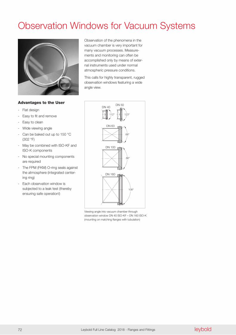
DN 50DN 40
DN 63
DN 100
DN 160
86°
108°
112° 123°
66°
leyboldLeybold Full Line Catalog 2018 - Flanges and Fittings72
Observation Windows for Vacuum Systems
Advantages to the User
- Flat design
- Easy to fit and remove
- Easy to clean
- Wide viewing angle
- Can be baked out up to 150 °C (302 °F)
- May be combined with ISO-KF and ISO-K components
- No special mounting components are required
- The FPM (FKM) O-ring seals against the atmosphere (integrated center-ing ring)
- Each observation window is subjected to a leak test (thereby ensuring safe operation!)
Observation of the phenomena in the vacuum chamber is very important for many vacuum processes . Measure-ments and monitoring can often be accomplished only by means of exter-nal instruments used under normal atmospheric pressure condi tions .
This calls for highly transparent, rugged observation windows featuring a wide angle view .
Viewing angle into vacuum chamber through ob servation window DN 40 ISO-KF – DN 160 ISO-K (mounting on matching flanges with tubulation)
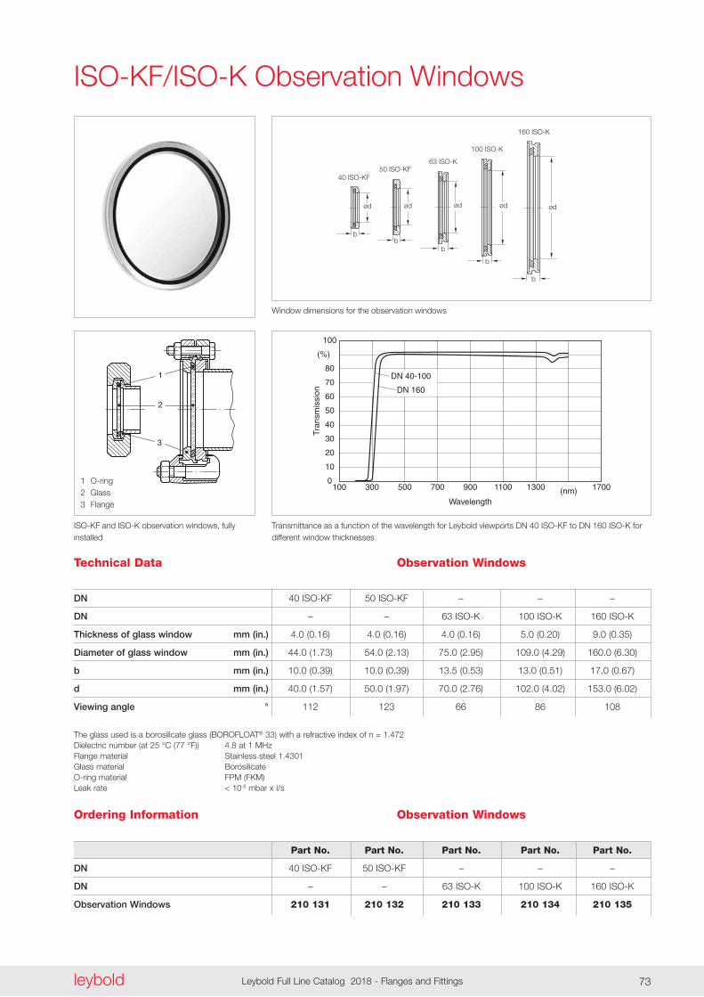
2
1
3
ødød ød ød
40 ISO-KF50 ISO-KF
63 ISO-K
100 ISO-K
160 ISO-K
ø153
17
ød
b
bb
b
b
07.04.K.002-Transmission
Tran
smis
sion
DN 40-100
DN 160
1000
10
20
30
40
50
60
70
80
(%)
100
300 500 700 900
Wavelength
1100 1300 (nm) 1700
leyboldLeybold Full Line Catalog 2018 - Flanges and Fittings72 leybold Leybold Full Line Catalog 2018 - Flanges and Fittings 73
ISO-KF and ISO-K observation windows, fully installed
1 O-ring2 Glass3 Flange
Window dimensions for the observation windows
Transmittance as a function of the wavelength for Leybold viewports DN 40 ISO-KF to DN 160 ISO-K for different window thicknesses
Technical Data Observation Windows
Ordering Information
Part No. Part No. Part No. Part No. Part No.
40 ISO-KF 50 ISO-KF – – –
– – 63 ISO-K 100 ISO-K 160 ISO-K
210 131 210 132 210 133 210 134 210 135
DN
DN
Thickness of glass window mm (in.)
Diameter of glass window mm (in.)
b mm (in.)
d mm (in.)
Viewing angle °
The glass used is a borosilicate glass (BOROFLOAT® 33) with a refractive index of n = 1 .472 Dielectric number (at 25 °C (77 °F)) 4 .8 at 1 MHz Flange material Stainless steel 1 .4301 Glass material Borosilicate O-ring material FPM (FKM) Leak rate < 10-8 mbar x l/s
40 ISO-KF 50 ISO-KF – – –
– – 63 ISO-K 100 ISO-K 160 ISO-K
4 .0 (0 .16) 4 .0 (0 .16) 4 .0 (0 .16) 5 .0 (0 .20) 9 .0 (0 .35)
44 .0 (1 .73) 54 .0 (2 .13) 75 .0 (2 .95) 109 .0 (4 .29) 160 .0 (6 .30)
10 .0 (0 .39) 10 .0 (0 .39) 13 .5 (0 .53) 13 .0 (0 .51) 17 .0 (0 .67)
40 .0 (1 .57) 50 .0 (1 .97) 70 .0 (2 .76) 102 .0 (4 .02) 153 .0 (6 .02)
112 123 66 86 108
DN
DN
Observation Windows
Observation Windows
ISO-KF/ISO-K Observation Windows
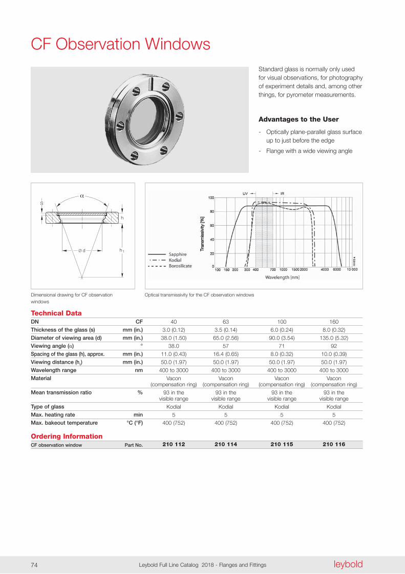
S
h
Ø d h1
leyboldLeybold Full Line Catalog 2018 - Flanges and Fittings74
CF Observation WindowsStandard glass is normally only used for visual observations, for photography of experiment details and, among other things, for pyrometer measurements .
Advantages to the User
- Optically plane-parallel glass surface up to just before the edge
- Flange with a wide viewing angle
Optical transmissivity for the CF observation windows Dimensional drawing for CF observation windows
Technical DataDN CF
Thickness of the glass (s) mm (in.)
Diameter of viewing area (d) mm (in.)
Viewing angle () °
Spacing of the glass (h), approx. mm (in.)
Viewing distance (h1) mm (in.)
Wavelength range nm
Material
Mean transmission ratio %
Type of glass
Max. heating rate min
Max. bakeout temperature °C (°F)
Ordering InformationCF observation window Part No.
40 63 100 160
3 .0 (0 .12) 3 .5 (0 .14) 6 .0 (0 .24) 8 .0 (0 .32)
38 .0 (1 .50) 65 .0 (2 .56) 90 .0 (3 .54) 135 .0 (5 .32)
38 .0 57 71 92
11 .0 (0 .43) 16 .4 (0 .65) 8 .0 (0 .32) 10 .0 (0 .39)
50 .0 (1 .97) 50 .0 (1 .97) 50 .0 (1 .97) 50 .0 (1 .97)
400 to 3000 400 to 3000 400 to 3000 400 to 3000
Vacon Vacon Vacon Vacon (compensation ring) (compensation ring) (compensation ring) (compensation ring)
93 in the 93 in the 93 in the 93 in the visible range visible range visible range visible range
Kodial Kodial Kodial Kodial
5 5 5 5
400 (752) 400 (752) 400 (752) 400 (752)
210 112 210 114 210 115 210 116
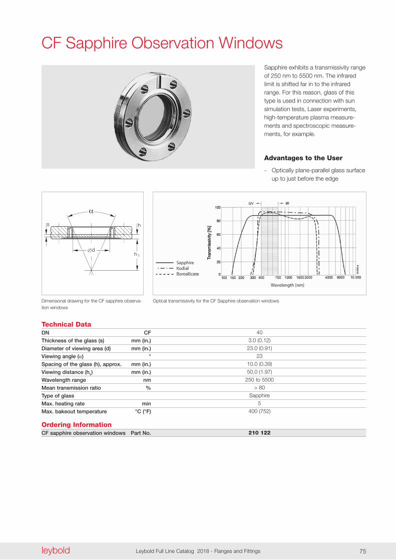
d
hs
h1
leyboldLeybold Full Line Catalog 2018 - Flanges and Fittings74 leybold Leybold Full Line Catalog 2018 - Flanges and Fittings 75
CF Sapphire Observation WindowsSapphire exhibits a transmissivity range of 250 nm to 5500 nm . The infrared limit is shifted far in to the infrared range . For this reason, glass of this type is used in connection with sun simulation tests, Laser experiments, high-temperature plasma measure-ments and spectroscopic measure-ments, for example .
Advantages to the User
- Optically plane-parallel glass surface up to just before the edge
Optical transmissivity for the CF Sapphire observation windows Dimensional drawing for the CF sapphire observa-tion windows
Technical DataDN CF
Thickness of the glass (s) mm (in.)
Diameter of viewing area (d) mm (in.)
Viewing angle () °
Spacing of the glass (h), approx. mm (in.)
Viewing distance (h1) mm (in.)
Wavelength range nm
Mean transmission ratio %
Type of glass
Max. heating rate min
Max. bakeout temperature °C (°F)
Ordering InformationCF sapphire observation windows Part No.
40
3 .0 (0 .12)
23 .0 (0 .91)
23
10 .0 (0 .39)
50 .0 (1 .97)
250 to 5500
> 80
Sapphire
5
400 (752)
210 122
Notes
leyboldLeybold Full Line Catalog 2018 - Flange and Fittings76 leybold Leybold Full Line Catalog 2018 - Flange and Fittings 77
POD_CP_080_EN_Flange_Fittings_LV_2016.indd 76 07.11.17 10:18