flaring and installation instructions 37 instructions.pdf · bolt torques for 37° flare flanges...
TRANSCRIPT
GS 37° Flare Flange SystemFlaring and Installation Instructions
2
GS–FLANGE SYSTEMGS 37° Flare Flange System
Introduction
GS 37° Connection technology
Selection of the pipe
Cutting of the pipe
Cleaning operations before flaring
Clamping the pipe
Flaring operations
Checking of the flaring
Assembling of parts
Connecting the joint
After installation
Reassembly
Appendix 1. Flared 37°joint
Appendix 2. Bolt torques and sizes
page
.................................................3
..................4
...................................5
......................................6
...........7
.......................................7
......................................8
...............................9
.................................10
.................................11
........................................12
................................................12
......................13
.........14
Table of contents

3
GS–FLANGE SYSTEMGS 37° Flare Flange System
Introduction
These are GS-Hydro’s guidelines for the manufacture and assembly of the GS-Hydro 37° flare flange system. In the case of special applications (special sealing arrangements, non-conductive connections, special materials etc) please contact GS-Hydro for further instructions.
In order to achieve the integrity required in any piping system it is imperative that operators are fully trained and conversant with the tools and machines to be used. GS-Hydro can provide training and instruction as well as installation supervision if required.
The GS 37° flare system is used for piping with pressure within range 50–420 bar. Extensive test programs – including rigorous vibration testing – have proven the suitability of the GS 37° flare flange system for a wide range of different materials and applications. GS-Hydro solutions are approved by many Classification companies for a wide range of materials and applications.
SAE 50 SAE 3000 SAE 6000 ISO 6164 / DIN
pressure, bar < 50 210 – 350 420 350-400
size, pipe 50x3 – 273x6 16x2 – 90x5 16x2 – 60x5 50x5 – 72x7
size, flange 1 1/2” – 10” 1/2” – 3” 1/2” – 2” 1 1/2” – 2 1/2”
material, pipe mild steel, galvanised steel, copper-nickel, aluminium/brass duplex, super duplex, titanium, tungum (elongation above 20%)
material, flange electric zinced carbon steel, hot dip galvanized carbon steel, stainless steel or titanium
material, seal Viton, NBR
Refer to the relevant health and safety instructions for protective measures.
Protect yourself always by using required personal protective equipments.

4
GS–FLANGE SYSTEMGS 37° Flare Flange System
GS-37° Connection Technology
The GS 37° flare flange system provides a variety of different ways to pipe connec-tions.
Type A/B utilises O-rings on all sealing surfaces.
Type C, with bonded seal, is a safe method of connection particularly in field conditions as inserts are identical.
Type D is an optional connection method when assembling long straight lines.
Type C added with extra sleeve, provides possibility to have flange and tube with different nominal sizes (i.e. 38 x 4 tube can be used with 1” SAE flange).

5
GS–FLANGE SYSTEMGS 37° Flare Flange System
Selection of the pipe
GS-Hydro recommends the use of cold drawn pipes & tubes due to the inherent quality, (precision dimensions and shape) and cleanliness, (no scale) characteristics. As a comparison, hot rolled tubes will always have scale both inside and outside due to the manufacturing process and may not be exactly round.
GS Hydro’s cold forming process ensures there will not be any scale inside the tube after the manufacturing.
Original GS-Hydro high-pressure piping can be recognised from the marking GS-PIPING along the tube length.
Carbon Steel
Material Specification DIN 1630 –
Manufacturing Tolerances DIN 2391-1 EN 10305-4
Technical Terms of Delivery DIN 2391-2/C EN 10305-4
Stainless Steel (mm) Stainless Steel (sch)
Material Specification ASTM A269/A213 (A.W.) ASTM A312
Manufacturing Tolerances ASTM A269 ASTM A530
GS-Hydro maintains a large stock of carbon and stainless steel pipes & tubes to be utilised in hydraulic and other piping systems:
All precision steel pipes are supplied with trace numbers.
Always keep the tubes stored indoors away from rain and moisture. Make sure all the tubes are protected with plastic plugs in the ends.

6
GS–FLANGE SYSTEMGS 37° Flare Flange System
Cutting off the pipe
When cutting a tube for GS 37° flare flange piping, the measurement C must be considered. This dimension “C” is the adjustment to the length of the tube to compensate for the dimension of the insert cone. Cut tubes squarely by using cold saw. Do not use roller cutter or grinder.
The measurement C is shown for the different flange types in Appendix 1, page 13.
After cutting the tube, make sure to put a plastic plug in the tube you do not use.
After cutting, the pipe is de-burred inside and outside; then wiped clean by cloth in order to remove any metal particles.
Especially with small size pipes (below 60 mm) it is recommended also to shoot foam projectiles by means of compressed air through pipes – use Jet Clean, Compri Tube Clean or respective method.
7
GS–FLANGE SYSTEMGS 37° Flare Flange System
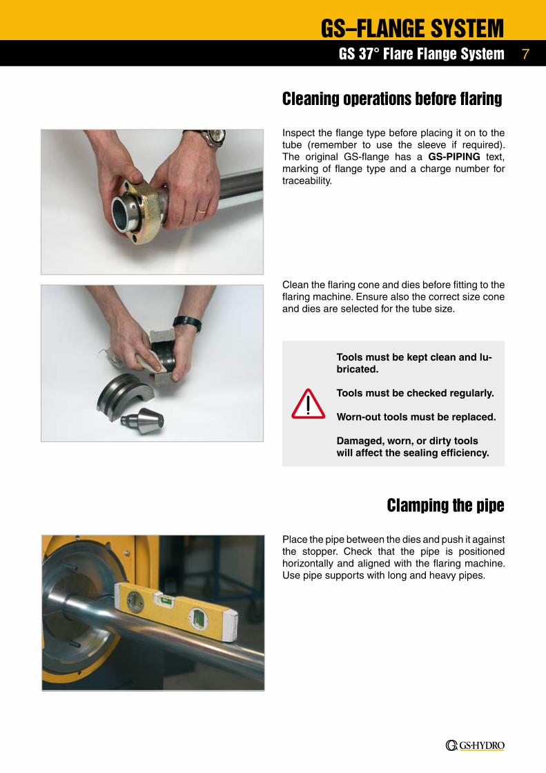
Cleaning operations before flaring
Inspect the flange type before placing it on to the tube (remember to use the sleeve if required). The original GS-flange has a GS-PIPING text, marking of flange type and a charge number for traceability.
Clean the flaring cone and dies before fitting to the flaring machine. Ensure also the correct size cone and dies are selected for the tube size.
Tools must be kept clean and lu-bricated.
Tools must be checked regularly.
Worn-out tools must be replaced.
Damaged, worn, or dirty tools will affect the sealing efficiency.
Clamping the pipe
Place the pipe between the dies and push it against the stopper. Check that the pipe is positioned horizontally and aligned with the flaring machine. Use pipe supports with long and heavy pipes.

8
GS–FLANGE SYSTEMGS 37° Flare Flange System
Flaring operations
Use only GS-Hydro flaring machine and genuine flaring cones and clamping dies.
It is recommended to carry out a test flare to find the exact setting of the stopper, the right pressure of the clamping jaws and the flaring pressure as well as the right time setting for the work cycle.
Before beginning the flaring operation check that the surface of the flaring cone has been thoroughly oiled or treated with Gleitmo 830 (Fuchs Lubritech) lubricating paste for cold forming.
After the flaring machine has been set up, the pipe to be flared is pushed into its jaws against the stopper and the jaws are locked (1). Then the pipe is flared (2).
Note that the flange is being placed onto pipe before flaring operation.
When the flare has been formed completely, it should be rolled another 3 to 5 more turns, before the cone is retracted.
For detailed information refer to the relevant operating instruc-tions of machine utilized.
Never reach into tool area while machine is working.
9
GS–FLANGE SYSTEMGS 37° Flare Flange System
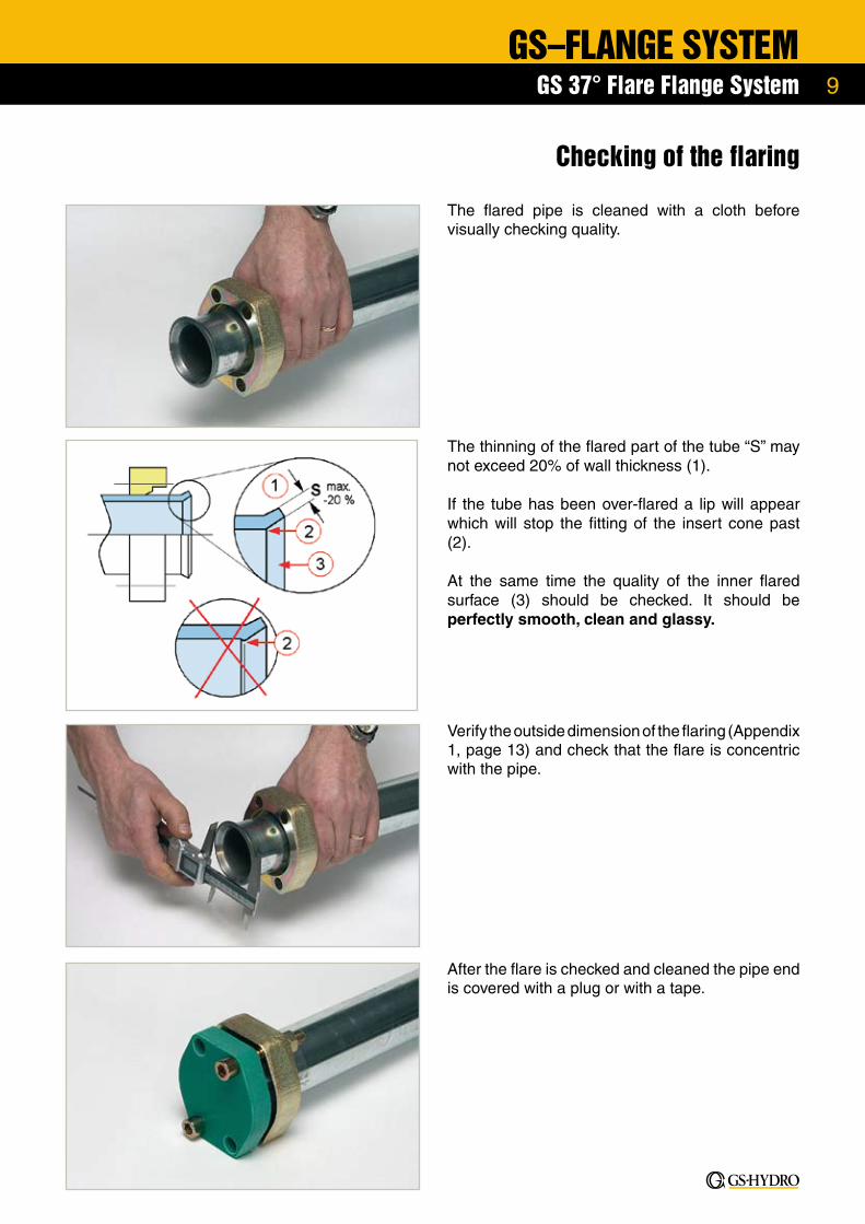
Checking of the flaring
The flared pipe is cleaned with a cloth before visually checking quality.
The thinning of the flared part of the tube “S” may not exceed 20% of wall thickness (1).
If the tube has been over-flared a lip will appear which will stop the fitting of the insert cone past (2).
At the same time the quality of the inner flared surface (3) should be checked. It should be perfectly smooth, clean and glassy.
Verify the outside dimension of the flaring (Appendix 1, page 13) and check that the flare is concentric with the pipe.
After the flare is checked and cleaned the pipe end is covered with a plug or with a tape.

10
GS–FLANGE SYSTEMGS 37° Flare Flange System
Assembling of parts
Inspect components prior to assembly:• use non-abrasive soft cloth to ensure all components are free from grease, dirt or any contaminants• verify that all components are of correct material and size
Lubricate the O-ring with system fluid or equivalent lubricant. Place O-ring carefully into its groove.
Examine all sealing surfaces to detect possible mechanical damages and rust.
Fit the insert cone into tube flare. If needed, tap gently with plastic or hide mallet.
Lubricate the bonded seal (dowty seal) with Gleitmo 805 -paste or equivalent.
11
GS–FLANGE SYSTEMGS 37° Flare Flange System
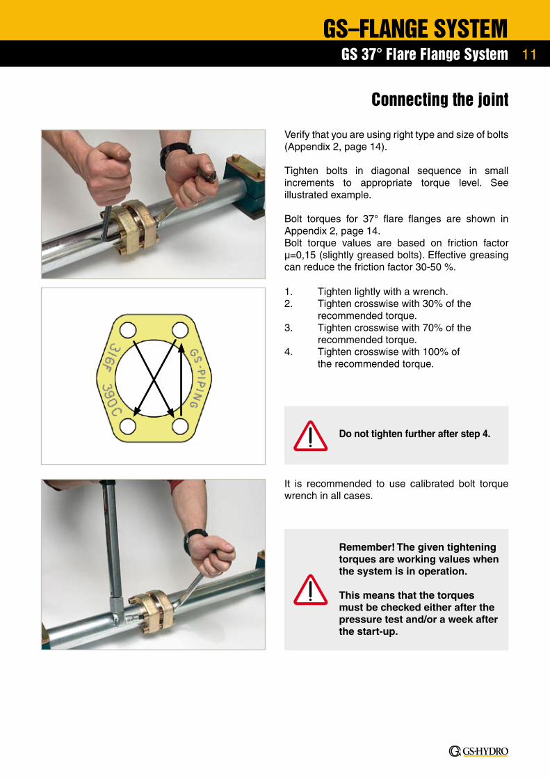
Connecting the joint
1. Tighten lightly with a wrench.2. Tighten crosswise with 30% of the recommended torque.3. Tighten crosswise with 70% of the recommended torque.4. Tighten crosswise with 100% of the recommended torque.
It is recommended to use calibrated bolt torque wrench in all cases.
Verify that you are using right type and size of bolts (Appendix 2, page 14).
Tighten bolts in diagonal sequence in small increments to appropriate torque level. See illustrated example.
Bolt torques for 37° flare flanges are shown in Appendix 2, page 14. Bolt torque values are based on friction factor µ=0,15 (slightly greased bolts). Effective greasing can reduce the friction factor 30-50 %.
Do not tighten further after step 4.
Remember! The given tightening torques are working values when the system is in operation.
This means that the torques must be checked either after the pressure test and/or a week after the start-up.
12
GS–FLANGE SYSTEMGS 37° Flare Flange System
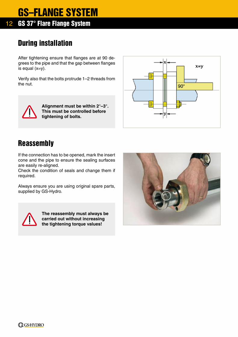
During installation
After tightening ensure that flanges are at 90 de-grees to the pipe and that the gap between flanges is equal (x=y).
Verify also that the bolts protrude 1–2 threads from the nut.
ReassemblyIf the connection has to be opened, mark the insert cone and the pipe to ensure the sealing surfaces are easily re-aligned.Check the condition of seals and change them if required.
Always ensure you are using original spare parts, supplied by GS-Hydro.
The reassembly must always be carried out without increasing the tightening torque values!
Alignment must be within 2°–3°. This must be controlled before tightening of bolts.

13
GS–FLANGE SYSTEMGS 37° Flare Flange System
Appendix 1. Flared 37° joint
SizePipe Size Part No D E C
1/2” 16x2.0 308/16X2.0FC 20 0 10
1/2” 18x2.0 308/18X2.0FC 22 0 11
1/2” 20x2.0 308/20X2.0FC 24 0 9
1/2” 25x2.5 308/25X2.5FC 29 0 9
1/2” 25x3.0 308/25X3.0FC 29 0 9
3/4” 20x2.0 312/20X2.0FC 24 0 12
3/4” 20x2.5 312/20X2.5FC 24 0 12
3/4” 25x2.5 312/25X2.5FC 29 0 9
3/4” 25x3.0 312/25X3.0FC 29 0 10
3/4” 30x3.0 312/30X3.0FC 36 0.5 9
1” 25x2.5 316/25X2.5FC 29 0 9
1” 25x3.0 316/25X3.0FC 29 0 9
1” 30x3.0 316/30X3.0FC 36 0.5 7
1” 30x4.0 316/30X4.0FC 36 0.5 7
1” 38x4.0 316/38X4.0FC 43.5 0.5 10
1 1/4” 30x3.0 320/30X3.0FC 36 0.5 10
1 1/4” 30x4.0 320/30X4.0FC 36.5 0.5 10
1 1/4” 38x4.0 320/38X4.0FC 43.5 0.5 9
1 1/4” 38x5.0 320/38X5.0FC 43.5 0.5 9
1 1/4” 42x4.0 320/42X4.0FC 48 0.5 11
1 1/2” 30x3.0 324/30X3.0FC 36.5 0.5 14
1 1/2” 38x4.0 324/38X4.0FC 43.5 0.5 13
1 1/2” 42x4.0 324/42X4.0FC 48 0.5 13
1 1/2” 50x5.0 324/50X5.0FC 58 1.0 11
2” 50x5.0 332/50X5.0FC 58 1.0 11
2” 60x5.0 332/60X5.0FC 68 1.5 11
2” 60x6.0 332/60X6.0FC 68 1.5 11
2 1/2” 60x5.0 340/60X5.0FC 68 1.5 12
2 1/2” 72x7.0 340/72X7.0FC 1.5 12
2 1/2” 75x5.0 340/75X5.0FC 83 1.5 13
3” 75x5.0 348/75X5.0FC 83 1.5 16
3” 90x5.0 348/90X5.0FC 100 1.5 14
SizePipe Size Part No D E C
1/2” 16x2.0 608/16X2.0FC 20 0 10
1/2” 18x2.0 608/18X2.0FC 22 0 11
1/2” 20x2.0 608/20X2.0FC 24 0 9
1/2” 25x2.5 608/25X2.5FC 29 0 9
1/2” 25x3.0 608/25X3.0FC 29 0 9
3/4” 20x2.0 612/20X2.0FC 24 0 12
3/4” 20x2.5 612/20X2.5FC 24 0 12
3/4” 25x2.5 612/25X2.5FC 29 0 9
3/4” 25x3.0 612/25X3.0FC 29 0 10
3/4” 30x3.0 612/30X3.0FC 36 0.5 9
3/4” 30x4.0 612/30X4.0FC 36 0.5 9
1” 25x2.5 616/25X2.5FC 29 0 9
1” 25x3.0 616/25X3.0FC 29 0 9
1” 30x3.0 616/30X3.0FC 36 0.5 7
1” 30x4.0 616/30X4.0FC 36 0.5 8
1” 38x4.0 616/38X4.0FC 43.5 0.5 10
1 1/4” 30x3.0 620/30X3.0FC 36 0.5 10
1 1/4” 30x4.0 620/30X4.0FC 36 0.5 10
1 1/4” 38x4.0 620/38X4.0FC 43.5 0.5 9
1 1/4” 38x5.0 620/38X5.0FC 43.5 0.5 9
1 1/4” 42x4.0 620/42X4.0FC 48 0.5 11
1 1/2” 30x3.0 624/30X3.0FC 36 0.5 14
1 1/2” 38x4.0 624/38X4.0FC 43.5 0.5 13
1 1/2” 38x5.0 624/38X5.0FC 43.5 0.5 13
1 1/2” 42x4.0 624/42X4.0FC 48 0.5 13
1 1/2” 50x5.0 624/50X5.0FC 58 1.5 11
2” 50x5.0 632/50X5.0FC 58 1.5 11
2” 60x5.0 632/60X5.0FC 68 1.5 11
2” 60x6.0 632/60X6.0FC 68 1.5 11
SizePipe Size Part No D E C
1 1/2” 50x3 124/50X3FA 58 1.0 12
2” 60x3 132/60X3FA 68 1.5 12
2 1/2” 75x3 140/75X3FA 83 1.5 13
3” 90x3.5 148/90X3.5FA 100 1.5 11
3 1/2” 100x4 156/100X4FA 110.8 1.5 18
4” 115x4 164/115X4FA 124.5 1.5 15
5” 140x4.5 180/140X4.5FA 150 1.5 16
6” 165x5 196/165X5FA 181 1.5 14
8” 220x6 228/220X6FA 236 1.5 18
10” 273x6 260/273X6FA 18

14
GS–FLANGE SYSTEMGS 37° Flare Flange System
Appendix 2. Bolt Torques
SAE 50 bar Bolt DIN 912, 8.8
SizeFlange Type
Bolt Torque
Flange to flange
Flange to block
1 1/2” 124F 50 Nm M12x70 x40
2” 132F 50 Nm M12x70 x40
2 1/2” 140F 50 Nm M12x70 x40
3” 148F 60 Nm M16x80 x50
3 1/2” 156F 70 Nm M16x90 x50
4” 164F 85 Nm M16x90 x50
5” 180F 125 Nm M16x90 x50
6” 196F 110 Nm M16x110 x60
8” 228F 200 Nm M20x120 x70
10” 260F 290 Nm M20x140 x80
SAE 3000 psi Bolt DIN 912, 8.8
SizeFlange Type
Bolt Torque
Flange to flange
Flange to block
1/2” 308F 20 Nm M8x60 x35
3/4” 312F 28 Nm M10x60 x35
1” 316F 37 Nm M10x60 x35
1 1/4” 320F 48 Nm M10x70 x35
1 1/2” 324F 62 Nm M12x80 x45
2” 332F 73 Nm M12x80 x50
2 1/2” 340F 107 Nm M12x110 x60
3” 348F 186 Nm M16x130 x80
SAE 6000 psi Bolt DIN 912, 8.8
SizeFlange Type
Bolt Torque
Flange to flange
Flange to block
1/2” 608F 20 Nm M8x60 x35
3/4” 612F 34 Nm M10x70 x40
1” 616F 56 Nm M12x70 x45
1 1/4” 620F 85 Nm M14x90 x50
1 1/2” 624F 158 Nm M16x100 x60
2” 632F 250 Nm M20x110 x70
DIN 350–400 bar Bolt DIN 912, 8.8
SizeFlange Type
Bolt Torque
Flange to flange
Flange to block
1 1/2” 424F 158 Nm M16x90 x50
2” 432F 200 Nm M16x90 x50
2 1/2” 440F 275 Nm M20x120 x70
SCH Serie SAE 3000 psi Bolt DIN 912, 8.8
SizeFlange Type
Bolt Torque
Flange to flange
Flange to block
1/2” 308/21.3F 20 Nm M8x60 x35
3/4” 312/26.7F 28 Nm M10x60 x35
1” 316/33.4F 37 Nm M10x60 x35
1 1/4” 320/42.2F 48 Nm M10x70 x35
1 1/2” 324/48.3F 62 Nm M12x80 x45
2” 332/60.3F 73 Nm M12x80 x50
2 1/2” 340/73F 107 Nm M12x110 x60
3” 348/88.9F 186 Nm M16x130 x80
SCH Serie SAE 6000 psi Bolt DIN 912, 8.8
SizeFlange Type
Bolt Torque
Flange to flange
Flange to block
1/2” 608/21.3F 20 Nm M8x60 x35
3/4” 612/26.7F 34 Nm M10x70 x40
1” 616/33.4F 56 Nm M12x70 x45
1 1/4” 620/42.2F 85 Nm M14x90 x50
1 1/2” 624/48.3F 158 Nm M16x100 x60
2” 632/60.3F 250 Nm M20x110 x70
SCH Serie DIN 350–400 bar Bolt DIN 912, 8.8
SizeFlange Type
Bolt Torque
Flange to flange
Flange to block
1 1/2” 424/48.3F 158 Nm M16x90 x50
2” 432/60.3F 200 Nm M16x90 x50
2 1/2” 440/73F 275 Nm M20x120 x70
15
GS–FLANGE SYSTEMGS 37° Flare Flange System
Notes
© G
S-H
ydro
Oy.
200
6. A
ll rig
hts
rese
rved
.
HEADQUARTERSGS-Hydro OyLautatarhankatu 4FI-13110 HämeenlinnaFINLANDTel. : +358 3 656 41E-mail: [email protected]
YOUR LOCAL SUBSIDIARY
www.gshydro.com
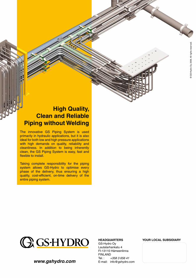
High Quality, Clean and Reliable
Piping without WeldingThe innovative GS Piping System is used primarily in hydraulic applications, but it is also ideal for both low and high pressure applications with high demands on quality, reliability and cleanliness. In addition to being inherently clean, the GS Piping System is easy, fast and flexible to install.
Taking complete responsibility for the piping system allows GS-Hydro to optimise every phase of the delivery, thus ensuring a high quality, cost-efficient, on-time delivery of the entire piping system.