flashstacktm mini converged infrastructure … · flashstack™ mini converged infrastructure...
TRANSCRIPT
FLASHSTACK™ MINI CONVERGED INFRASTRUCTUREDesign Guide for Microsoft Applications with Hyper-VJanuary 2017
©2017 Pure Storage, Inc. 1
TABLE OF CONTENTS
EXECUTIVE OVERVIEW ................................................................................................................... 3
GOALS AND OBJECTIVES ............................................................................................................... 3
AUDIENCE .............................................................................................................................................. 4
DESIGN PRINCIPLES .......................................................................................................................... 4
FLASHSTACK MINI – INTRODUCTION ................................................................................... 5
FLASHSTACK MINI FOR MICROSOFT APPLICATION
CONSOLIDATION – DESIGN OVERVIEW ................................................................................ 7
SIMPLIFIED DEPLOYMENT FOR CONSOLIDATED
MICROSOFT SOLUTIONS ON FLASHSTACK MINI ........................................................... 8
LOGICAL INFRASTRUCTURE ARCHITECTURE ...................................................................... 8
CONFIGURATION ............................................................................................................................... 10
SETTING UP UCS SERVICE PROFILE ......................................................................................... 10
DEPLOY WINDOWS SERVER 2012 R2 (SAN BOOT) ............................................................ 16
DEPLOYING WINDOWS SERVER FAILOVER CLUSTERS .................................................... 21
SETTING UP MICROSOFT SYSTEM CENTER VIRTUAL
MACHINE MANAGER (SCVMM) 2012 R2 ................................................................................ 22
CONFIGURING CONTINUOUSLY AVAILABLE FILE SHARES ........................................... 29
PERFORMANCE BENCHMARKING ......................................................................................... 33
MICROSOFT WINDOWS 10 BOOT STORM ............................................................................. 33
SYNCHRONOUS BOOT .............................................................................................................. 33
ASYNCHRONOUS BOOT ........................................................................................................... 34
MICROSOFT SQL SERVER 2014 OLTP + DSS WORKLOADS ............................................ 36
ONLINE TRANSACTION PROCESSING (OLTP) .................................................................... 36
DECISION SUPPORT SYSTEM (DSS) ....................................................................................... 36
MICROSOFT EXCHANGE SERVER WORKLOAD ..................................................................... 37
ALL WORKLOADS COMBINED .................................................................................................... 43
DATA REDUCTION ............................................................................................................................ 44
CONCLUSION ...................................................................................................................................... 45
©2017 Pure Storage, Inc. 2
APPENDIX 1: PURE STORAGE COMPONENTS IN FLASHSTACK .......................... 46
FLASHARRAY//M ............................................................................................................................. 46
PURITY OPERATING ENVIRONMENT ....................................................................................... 47
PURE1® – COMPONENT FEATURES ......................................................................................... 48
APPENDIX 2: CISCO COMPONENTS IN FLASHSTACK MINI ................................... 48
CISCO UCS 5108 CHASSIS ........................................................................................................... 50
CISCO UCS 6324 FABRIC INTERCONNECT .......................................................................... 50
CISCO UCS B200-M4 SERVERS .................................................................................................. 51
©2017 Pure Storage, Inc. 3
EXECUTIVE OVERVIEW FlashStack™ Mini from Pure Storage® extends the FlashStack converged infrastructure platform into a smaller, more economical form factor designed for consolidated workloads and private cloud deployments. FlashStack Mini is built from market leading components from Cisco® and Pure Storage. FlashStack Mini integrates Cisco’s extremely flexible and expandable Unified Computing System (UCS®) platform to offer network and compute capabilities and Pure Storage FlashArray//M as the Smart Storage foundation. FlashStack Mini is delivered via skilled joint Cisco and Pure Storage reseller partners who provide the guidance, services, and experience necessary to help you deploy FlashStack Mini quickly and with confidence. Single-number unified support for FlashStack (including systems and software) is provided directly by Cisco or by FlashStack Authorized Support.
FlashStack Mini is sized to meet the needs of smaller IT deployments such as those of small- to medium-sized organizations or for larger enterprises who want the power of FlashStack for their remote or branch offices.
Traditional models for IT delivery consist of infrastructure silos leading to low utilization and high labor costs. Each infrastructure appliance has a standalone management interface and requires expensive specialized training. Organizations are constantly challenged to provide a robust, predictable, and dependable enviroment in the backdrop of ever-increasing volume of data, users, and operations. Given this, the deployment of data center infrastructure can be complex, time consuming, and costly. It is the goal of FlashStack (including FlashStack Mini) to provide the reliable, scalable, easy- to-manage, and high performance platform for consolidated workloads and private cloud environments.
This document describes a reference architecture for deploying consolidated Microsoft® workloads on a FlashStack Mini Converged Infrastructure with Microsoft Windows® Server Hyper-V®. The goal of this document is to showcase the ease of deploying a consolidated Microsoft applications environment with Microsoft Windows 10 desktops, multiple Microsoft SQL Server 2014 instances, Microsoft Exchange® 2016, Microsoft SharePoint® 2016, and home directories using SMB on the FlashStack Mini. Management of the environment is handled using Microsoft System Center Virtual Machine Manager 2012 R2 and templates as the virtual machine building blocks.
Several building blocks deployed to showcase online transaction processing (OLTP), data warehouse (DSS), messaging, and collaboration workloads will illustrate predictable out-of-the-box performance without over-subscribing CPU or memory resources. In addition, we highlight the benefits of FlashStack Mini, including data reduction and low latency that directly impacts the user experience and provides customers a smart, efficient, and Evergreen™ storage foundation for their large-scale Microsoft application deployment projects.
GOALS AND OBJECTIVESThe goal of this document is to showcase the scalability and the resilience of FlashStack Mini when tier-1 application workloads such as desktop virtualization, databases, messaging, and collaboration are run simultaneously and at high load. The test data will show consistent sub-millisecond response times when multiple workloads are in

©2017 Pure Storage, Inc. 4
simultaneous operation. Pure Storage has validated the reference architecture within its lab: this document presents the hardware and software configuration, the test workload configuration, and testing results, and further offers implementation and sizing guidance for a mixed workload. This document will show the following:
• Microsoft SharePoint – Leveraging pass-through disks, Microsoft SharePoint workload simulated hundreds of active users, with multiple requests from different clients.
• SQL Server OLTP – This tests all components of the server and storage subsystems by stressing the physical I/O layer of SQL Server through random Read/Write I/O, without being limited to a specific load-generating application.
• SQL Server DSS – A DSS workload using a 500GB dataset is simulated using HammerDB, an industry-standard, open source database load testing and benchmarking tool. This simulates hundreds of users logged in at the same time and loading the SQL Server database with thousands of simultaneous queries. This comprises both database updates and read-only queries.
• Microsoft Exchange, 300 mailboxes – Microsoft Exchange Jetstress workload replicates the storage activity of typical e-mail users. Jetstress simulates the Exchange database and log file loads produced by a specified number of users.
• Windows 10 Remote Desktops – 300 Windows 10 desktop virtual machines running with Visual Studio® 2015 and Office 2016.
• Server Message Block (SMB) – High-Availability file shares using Windows Server File and Storage Services.
• Domain User Home Directories – Home directories for individual user storage using Windows Server File and Storage Services.
AUDIENCEThe target audience for this document consists of IT admins, architects, and application owners such as Exchange admins, SharePoint admins, and SQL DBAs. This is also useful for storage and virtualization administrators, data center architects, and field engineers who want to implement Microsoft HyperV-based virtualized solutions, particularly private cloud systems. A working knowledge of Microsoft System Center, Microsoft Hyper-V, Microsoft SQL Server, server, storage, networks, and data center design is assumed but is not a prerequisite to read this document.
DESIGN PRINCIPLESThe guiding principles for implementing this design are:
• Availability – Create a design that is resilient and not prone to failure of a single component. For example, we include best practices to enforce multiple paths to storage, multiple NICs for connectivity, and high availability using System Center Virtual Machine Manager (VMM) 2012 R2 with Windows Server Failover Clustering and Hyper-V.
©2017 Pure Storage, Inc. 5
• Performance – Make sure that the design ensures databases respond to users and applications in a timely manner. All best practices used for Microsoft SQL Server are from the Pure Storage SQL Server Best Practices guide.
• Simplified and Repeatable Provisioning – Create virtual machine templates that provide a building block for Microsoft SQL Server and Windows 10 desktop deployments.
• Consolidation – Take advantage of technologies from Cisco and Pure Storage to help virtualize and consolidate workloads from multiple application workloads.
FLASHSTACK MINI – INTRODUCTIONFlashStack – built with market leading components from Cisco and Pure Storage – is an ideal fit for infrastructure requirements for small- to medium-sized IT environments. FlashStack Mini extends the FlashStack solution range by leveraging the smaller form factor Cisco “UCS Mini” which combines fabric extenders and fabric interconnects into the Cisco UCS chassis. With storage, compute, network, and virtualization capabilities integrated in an easy-to-deploy, compact form factor, FlashStack Mini provides a comprehensive solution that can scale up, without disruption, based on business needs.
FlashStack Mini offers a set of pre-validated solutions that can be deployed seamlessly.
• Storage – Pure Storage FlashArray//M brings Smart Storage to businesses of every size and provides all-flash storage in a modular, stateless architecture, enabling non-disruptive upgrades as dictated by business needs. FlashArray//M leverages a chassis-based design with customizable modules, enabling both capacity and performance to be independently improved over time.
• Compute and Network – The compute and networking component, Cisco’s Unified Communication Manager (UCS) Mini solution delivers servers, storage, and 10 Gigabit networking in an easy-to-deploy, compact form factor. Cisco UCS Mini reduces TCO (total cost of ownership) by consolidating management modules into the chassis, making the chassis stateless, and by reducing the number of network interface cards (NICs), host bus adapters (HBAs), switches, and cables needed.
• Virtualization – With support for multiple hypervisors, FlashStack Mini provides a robust, production-proven, high-performance solution for virtualized environments. It enables multiple virtual machines to share hardware resources with performance that can match (and in some cases exceed) native throughput.
FlashStack Mini offers the following advantages:
• Small Form Factor, Mighty Performance – FlashStack Mini provides all-flash performance, integrated compute and networking, and no-compromise enterprise capabilities in a small, efficient 9U form factor.
©2017 Pure Storage, Inc. 6
• Reduced Complexity and Cost – Fully tested, validated, and documented blueprint facilitates rapid and repeatable deployment. Simplified deployment translates to low operational upkeep and accelerated time to value.
• Consolidate Multiple Workloads – Allows for consolidation of common applications such as server and desktop virtualization, email and business applications on an easy to use infrastructure solution. Consolidation of operations reduces server and storage requirements and eliminates IT infrastructure silos.
• Private Cloud Foundation – Enables virtualization, consolidation, automation, and self-service of IT infrastructure that improves IT and organizational agility.
Please see appendices to this document for a detailed overview of Cisco UCS, Cisco Nexus, Pure Storage FlashArray//M, and Microsoft components used in this design guide.
©2017 Pure Storage, Inc. 7
FLASHSTACK MINI FOR MICROSOFT APPLICATION CONSOLIDATION – DESIGN OVERVIEWAs IT business needs grow, increased use of server and desktop virtualization against a backdrop of higher data management is a reality. When virtualization is leveraged to consolidate workloads, infrastructure efficiency is at its peak performance, with better resource utilization. In this Microsoft workload consolidation solution testing, the following critical applications were consolidated on a single FlashArray//M: Microsoft Exchange Server 2016, Microsoft SharePoint Foundation 2016, Microsoft SQL Server 2014, and Windows 10 remote desktops.
The use cases in the testing scenarios will demonstrate the following:
• Simplified deployment and workload consolidation with FlashStack Mini Converged Infrastructure (CI)
• Simplified day to day management, infrastructure availability, and elasticity with FlashStack Mini CI
• Secured infrastructure
• Ultimate performance for mixed workloads
• Data reduction efficiency
The business advantages of the core technologies used in this reference architecture are described below:
• Provides high availability for all virtual machines at a low cost (compared to purchasing an HA solution on a per-machine basis). The use of System Center Virtual Machine Manager (VMM) 2012 R2 and Windows Server Failover Clustering from Windows Server 2012 R2 provides a high-availability solution for all virtual machines with shared storage using Clustered Shared Volumes (CSV).
• Ability to setup this solution using Windows PowerShell with the new Pure Storage PowerShell SDK and support via cmdlets for Windows Server Failover Clustering, System Center, Hyper-V and SQL Server, provides a tremendous automation framework for repeatable and rapid deployments.
Five common, mission-critical applications were deployed:
• Virtualization – Windows Server 2012 R2 (Hyper-V)
• Messaging – Microsoft Exchange Server 2016
• Collaboration – Microsoft SharePoint Foundation 2016
• Database Services – Microsoft SQL Server 2014
• Desktop Services – Windows 10
©2017 Pure Storage, Inc. 8
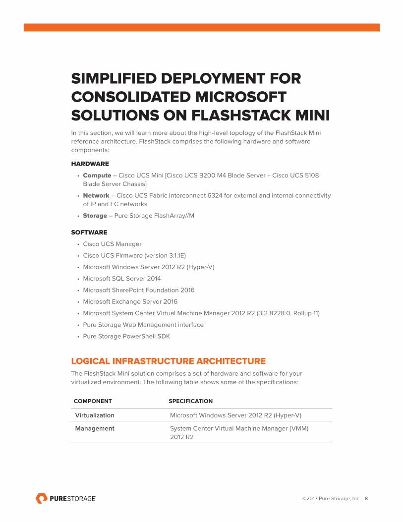
SIMPLIFIED DEPLOYMENT FOR CONSOLIDATED MICROSOFT SOLUTIONS ON FLASHSTACK MINIIn this section, we will learn more about the high-level topology of the FlashStack Mini reference architecture. FlashStack comprises the following hardware and software components:
HARDWARE
• Compute – Cisco UCS Mini [Cisco UCS B200 M4 Blade Server + Cisco UCS 5108 Blade Server Chassis]
• Network – Cisco UCS Fabric Interconnect 6324 for external and internal connectivity of IP and FC networks.
• Storage – Pure Storage FlashArray//M
SOFTWARE
• Cisco UCS Manager
• Cisco UCS Firmware (version 3.1.1E)
• Microsoft Windows Server 2012 R2 (Hyper-V)
• Microsoft SQL Server 2014
• Microsoft SharePoint Foundation 2016
• Microsoft Exchange Server 2016
• Microsoft System Center Virtual Machine Manager 2012 R2 (3.2.8228.0, Rollup 11)
• Pure Storage Web Management interface
• Pure Storage PowerShell SDK
LOGICAL INFRASTRUCTURE ARCHITECTUREThe FlashStack Mini solution comprises a set of hardware and software for your virtualized environment. The following table shows some of the specifications:
COMPONENT SPECIFICATION
Virtualization Microsoft Windows Server 2012 R2 (Hyper-V)
Management System Center Virtual Machine Manager (VMM) 2012 R2
©2017 Pure Storage, Inc. 9
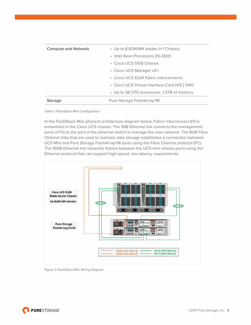
Compute and Network • Up to 8 B240M4 blades in 1 Chassis
• Intel Xeon Processors E5-2600
• Cisco UCS 5108 Chassis
• Cisco UCS Manager v3.1
• Cisco UCS 6324 Fabric Interconnects
• Cisco UCS Virtual Interface Card (VIC) 1340
• Up to 36 CPU processors, 1.5TB of memory
Storage Pure Storage FlashArray//M
Table 1: FlashStack Mini Configuration
In the FlashStack Mini physical architecture diagram below, Fabric Interconnect (FI) is embedded in the Cisco UCS chassis. The 1GB Ethernet link connects the management ports of FIs to the port of the ethernet switch to manage the core network. The 8GB Fibre Channel links that are used to maintain data storage establishes a connection between UCS Mini and Pure Storage FlashArray//M ports using the Fibre Channel protocol (FC). The 10GB Ethernet link transmits frames between the UCS mini chassis ports using the Ethernet protocol that can support high-speed, low-latency requirements.
Figure 1: FlashStack Mini Wiring Diagram
©2017 Pure Storage, Inc. 10
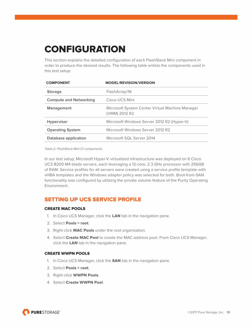
CONFIGURATIONThis section explains the detailed configuration of each FlashStack Mini component in order to produce the desired results. The following table enlists the components used in this test setup:
COMPONENT MODEL/REVISION/VERSION
Storage FlashArray//M
Compute and Networking Cisco UCS Mini
Management Microsoft System Center Virtual Machine Manager (VMM) 2012 R2
Hypervisor Microsoft Windows Server 2012 R2 (Hyper-V)
Operating System Microsoft Windows Server 2012 R2
Database application Microsoft SQL Server 2014
Table 2. FlashStack Mini CI components
In our test setup, Microsoft Hyper-V virtualized infrastructure was deployed on 6 Cisco UCS B200 M4 blade servers, each leveraging a 12-core, 2.3 GHz processor with 256GB of RAM. Service profiles for all servers were created using a service profile template with vHBA templates and the Windows adapter policy was selected for both. Boot-from-SAN functionality was configured by utilizing the private volume feature of the Purity Operating Environment.
SETTING UP UCS SERVICE PROFILE
CREATE MAC POOLS
1. In Cisco UCS Manager, click the LAN tab in the navigation pane.
2. Select Pools > root.
3. Right-click MAC Pools under the root organization.
4. Select Create MAC Pool to create the MAC address pool. From Cisco UCS Manager, click the LAN tab in the navigation pane.
CREATE WWPN POOLS
1. In Cisco UCS Manager, click the SAN tab in the navigation pane.
2. Select Pools > root.
3. Right-click WWPN Pools.
4. Select Create WWPN Pool.
©2017 Pure Storage, Inc. 11
CREATE UUID SUFFIX POOL
1. In Cisco UCS Manager, click the Servers tab in the navigation pane.
2. Select Pools > root.
3. Right-click UUID Suffix Pools.
4. Select Create UUID Suffix Pool.
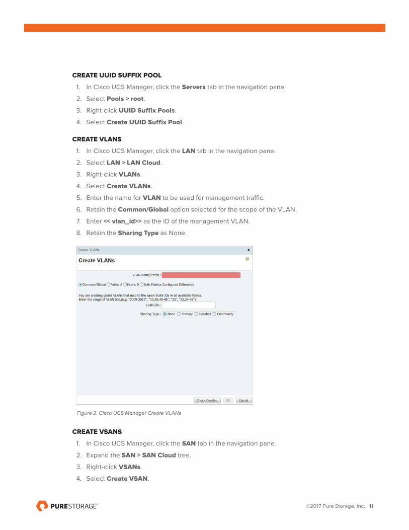
CREATE VLANS
1. In Cisco UCS Manager, click the LAN tab in the navigation pane.
2. Select LAN > LAN Cloud.
3. Right-click VLANs.
4. Select Create VLANs.
5. Enter the name for VLAN to be used for management traffic.
6. Retain the Common/Global option selected for the scope of the VLAN.
7. Enter << vlan_id>> as the ID of the management VLAN.
8. Retain the Sharing Type as None.
Figure 2. Cisco UCS Manager Create VLANs
CREATE VSANS
1. In Cisco UCS Manager, click the SAN tab in the navigation pane.
2. Expand the SAN > SAN Cloud tree.
3. Right-click VSANs.
4. Select Create VSAN.
©2017 Pure Storage, Inc. 12
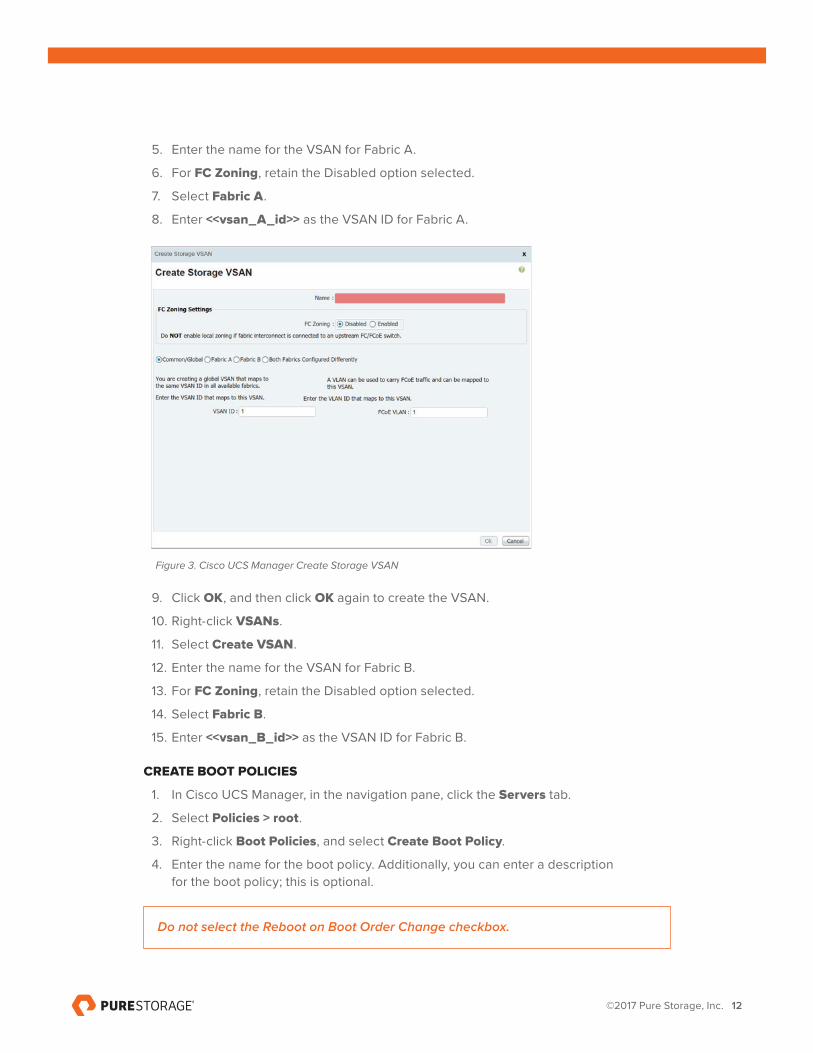
5. Enter the name for the VSAN for Fabric A.
6. For FC Zoning, retain the Disabled option selected.
7. Select Fabric A.
8. Enter <<vsan_A_id>> as the VSAN ID for Fabric A.
Figure 3. Cisco UCS Manager Create Storage VSAN
9. Click OK, and then click OK again to create the VSAN.
10. Right-click VSANs.
11. Select Create VSAN.
12. Enter the name for the VSAN for Fabric B.
13. For FC Zoning, retain the Disabled option selected.
14. Select Fabric B.
15. Enter <<vsan_B_id>> as the VSAN ID for Fabric B.
CREATE BOOT POLICIES
1. In Cisco UCS Manager, in the navigation pane, click the Servers tab.
2. Select Policies > root.
3. Right-click Boot Policies, and select Create Boot Policy.
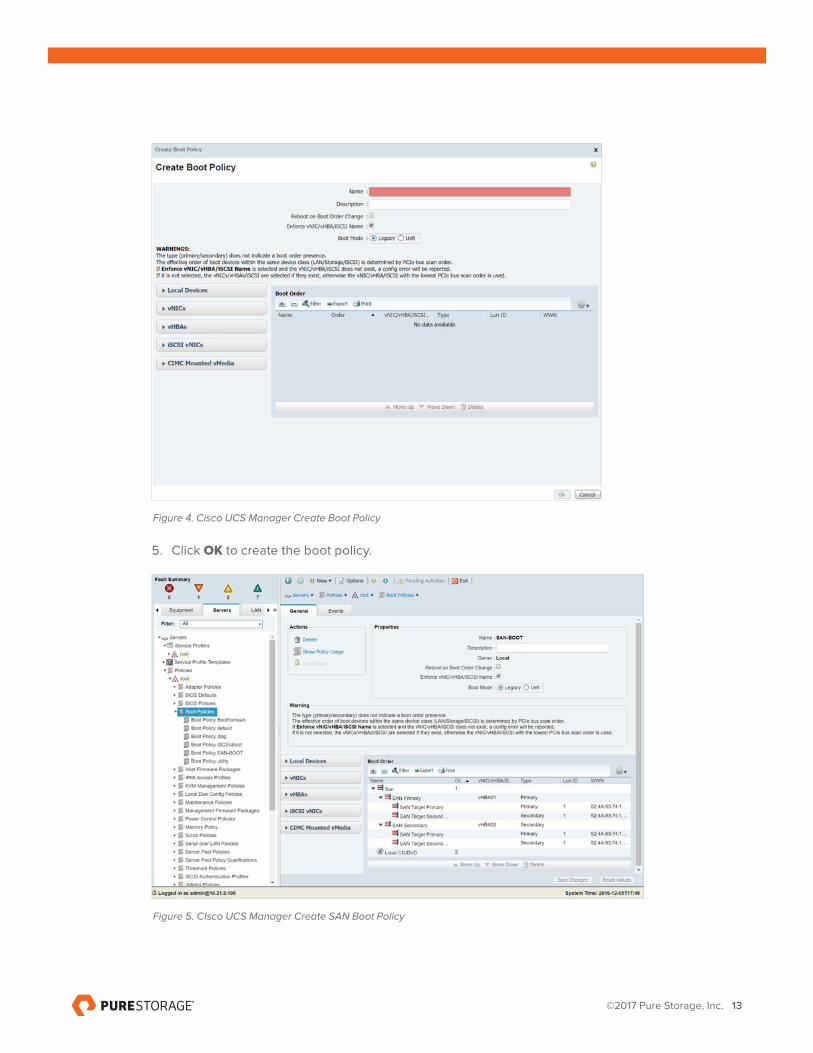
4. Enter the name for the boot policy. Additionally, you can enter a description for the boot policy; this is optional.
Do not select the Reboot on Boot Order Change checkbox.
©2017 Pure Storage, Inc. 13
Figure 4. Cisco UCS Manager Create Boot Policy
5. Click OK to create the boot policy.
Figure 5. CIsco UCS Manager Create SAN Boot Policy
©2017 Pure Storage, Inc. 14
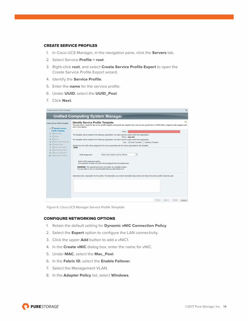
CREATE SERVICE PROFILES
1. In Cisco UCS Manager, in the navigation pane, click the Servers tab.
2. Select Service Profile > root.
3. Right-click root, and select Create Service Profile Export to open the Create Service Profile Export wizard.
4. Identify the Service Profile.
5. Enter the name for the service profile.
6. Under UUID, select the UUID_Pool.
7. Click Next.
Figure 6. Cisco UCS Manager Service Profile Template
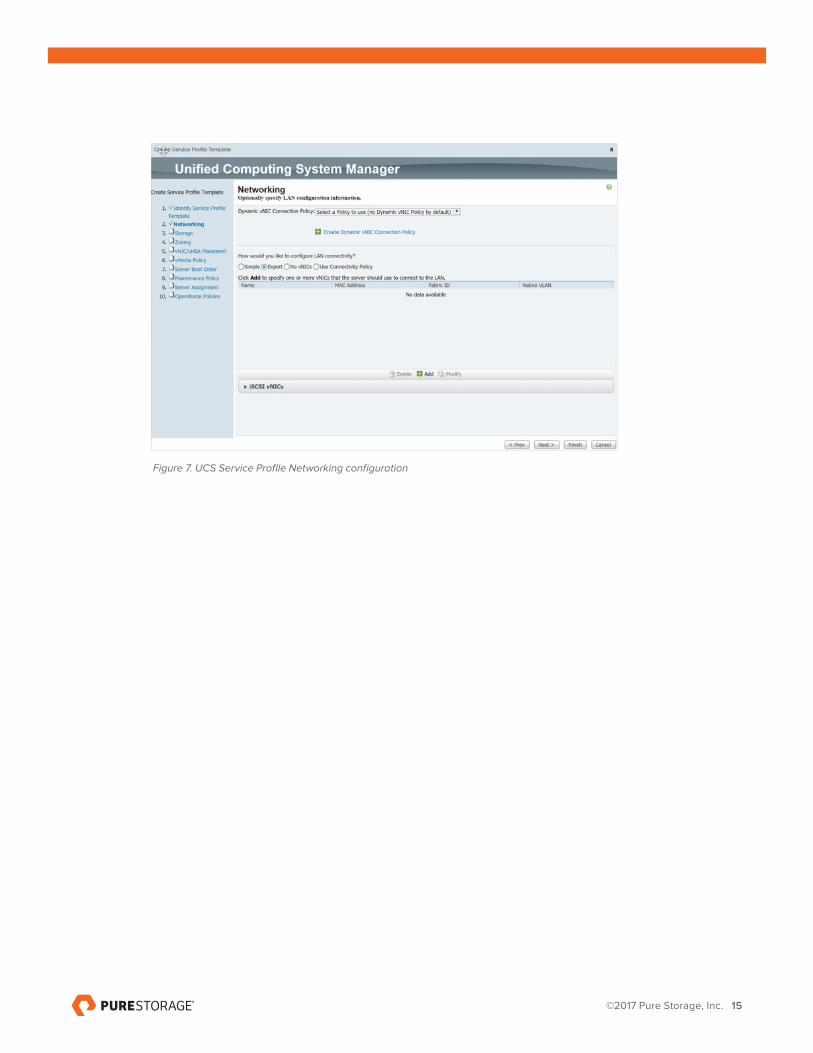
CONFIGURE NETWORKING OPTIONS
1. Retain the default setting for Dynamic vNIC Connection Policy.
2. Select the Expert option to configure the LAN connectivity.
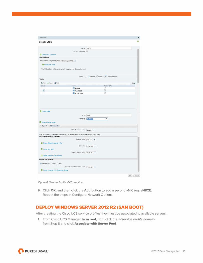
3. Click the upper Add button to add a vNIC1.
4. In the Create vNIC dialog box, enter the name for vNIC.
5. Under MAC, select the Mac_Pool.
6. In the Fabric ID, select the Enable Failover.
7. Select the Management VLAN.
8. In the Adapter Policy list, select Windows.
©2017 Pure Storage, Inc. 15
Figure 7. UCS Service Proflle Networking configuration
©2017 Pure Storage, Inc. 16
Figure 8. Service Profile vNIC creation
9. Click OK, and then click the Add button to add a second vNIC (eg. vNIC2). Repeat the steps in Configure Network Options.
DEPLOY WINDOWS SERVER 2012 R2 (SAN BOOT)After creating the Cisco UCS service profiles they must be associated to available servers.
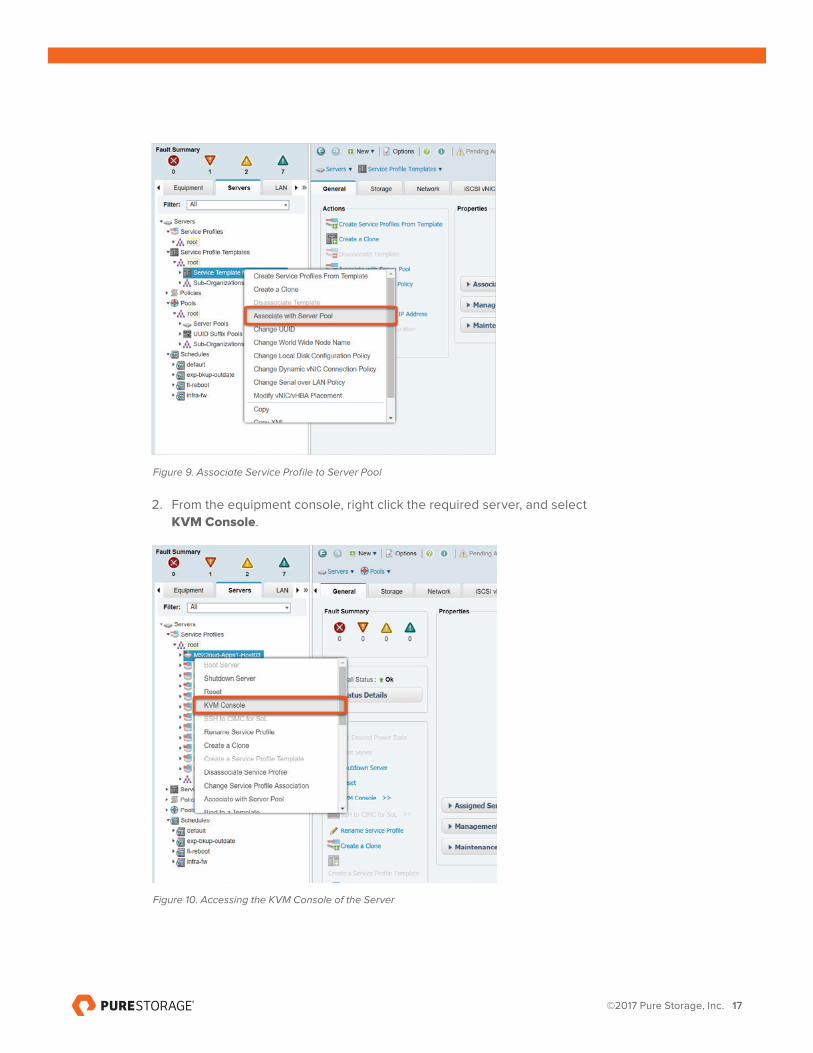
1. From Cisco UCS Manager, from root, right click the <<service profile name>> from Step 8 and click Associate with Server Pool.
©2017 Pure Storage, Inc. 17
Figure 9. Associate Service Profile to Server Pool
2. From the equipment console, right click the required server, and select KVM Console.
Figure 10. Accessing the KVM Console of the Server
©2017 Pure Storage, Inc. 18
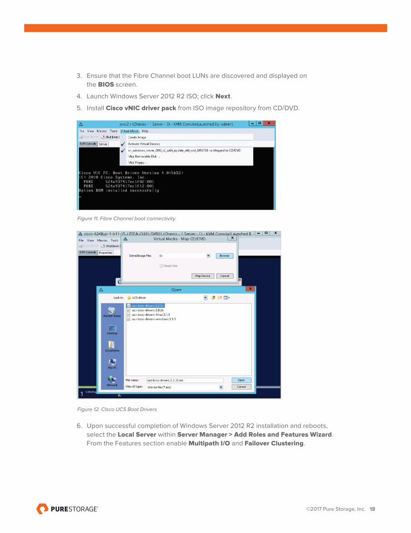
3. Ensure that the Fibre Channel boot LUNs are discovered and displayed on the BIOS screen.
4. Launch Windows Server 2012 R2 ISO; click Next.
5. Install Cisco vNIC driver pack from ISO image repository from CD/DVD.
Figure 11. Fibre Channel boot connectivity
Figure 12. CIsco UCS Boot Drivers
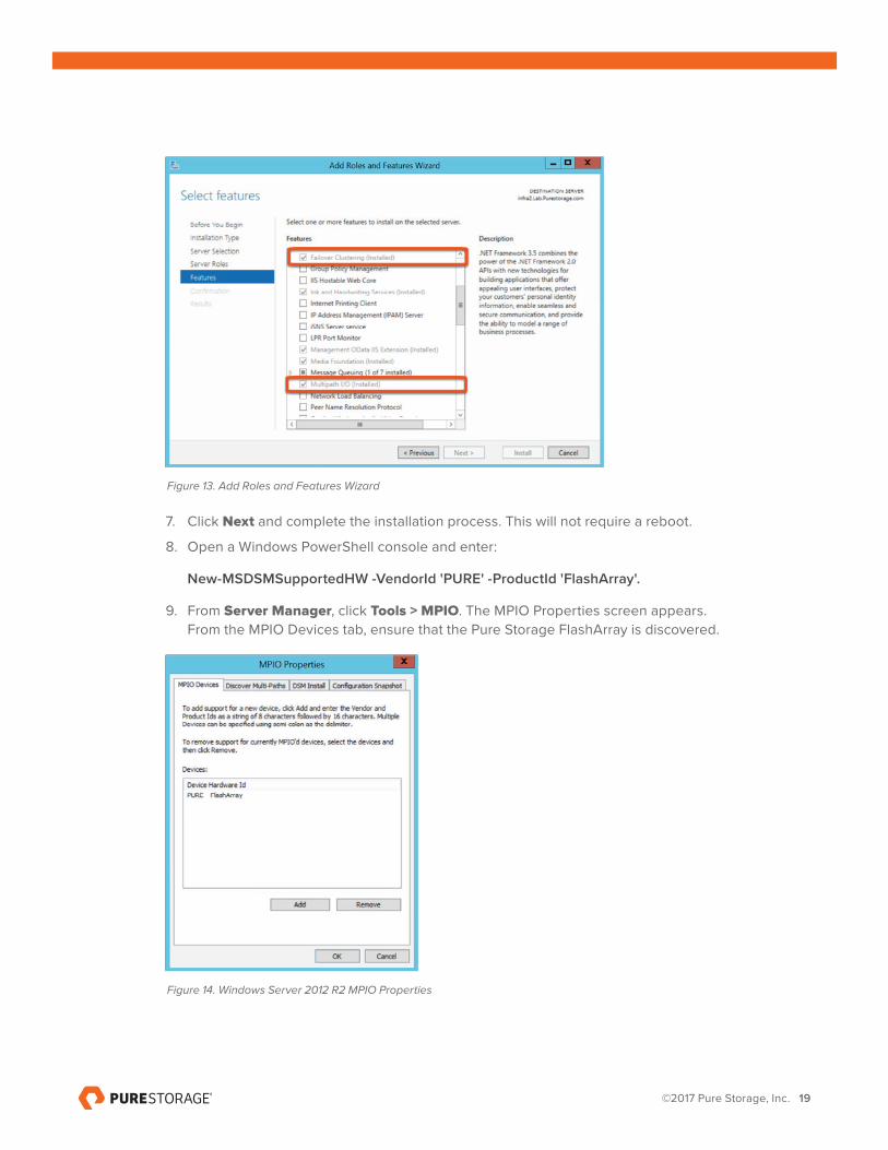
6. Upon successful completion of Windows Server 2012 R2 installation and reboots, select the Local Server within Server Manager > Add Roles and Features Wizard. From the Features section enable Multipath I/O and Failover Clustering.
©2017 Pure Storage, Inc. 19
Figure 13. Add Roles and Features Wizard
7. Click Next and complete the installation process. This will not require a reboot.
8. Open a Windows PowerShell console and enter:
New-MSDSMSupportedHW -VendorId 'PURE' -ProductId 'FlashArray'.
9. From Server Manager, click Tools > MPIO. The MPIO Properties screen appears. From the MPIO Devices tab, ensure that the Pure Storage FlashArray is discovered.
Figure 14. Windows Server 2012 R2 MPIO Properties
©2017 Pure Storage, Inc. 20
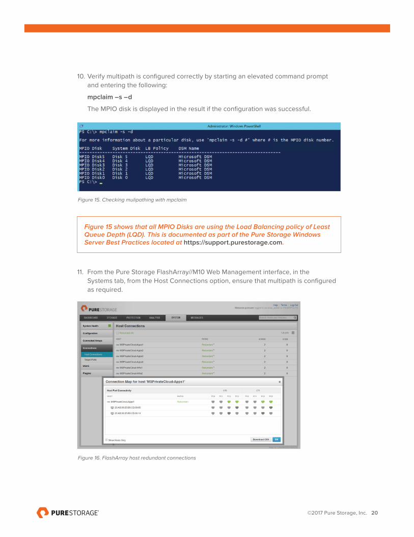
10. Verify multipath is configured correctly by starting an elevated command prompt and entering the following:
mpclaim –s –d
The MPIO disk is displayed in the result if the configuration was successful.
Figure 15. Checking mulipathing with mpclaim
Figure 15 shows that all MPIO Disks are using the Load Balancing policy of Least Queue Depth (LQD). This is documented as part of the Pure Storage Windows Server Best Practices located at https://support.purestorage.com.
11. From the Pure Storage FlashArray//M10 Web Management interface, in the Systems tab, from the Host Connections option, ensure that multipath is configured as required.
Figure 16. FlashArray host redundant connections
©2017 Pure Storage, Inc. 21
DEPLOYING WINDOWS SERVER FAILOVER CLUSTERS
CREATING FAILOVER CLUSTERING FEATURE
1. Start Server Manager.
2. On the Manage menu, click Add Roles and Features.
3. On the Before you begin page, click Next.
4. On the Select installation type page, click Role-based or feature-based installation, and then click Next.
5. On the Select destination server page, click the server where you want to install the feature, and then click Next.
6. On the Select server roles page, click Next.
7. On the Select features page, select the Failover Clustering check box.
8. To install the failover cluster management tools, click Add Features, and then click Next.
9. On the Confirm installation selections page, click Install.
10. When the installation is completed, click Close.
11. Repeat this procedure on every server that you want to add as a failover cluster node.
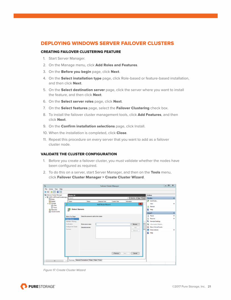
VALIDATE THE CLUSTER CONFIGURATION
1. Before you create a failover cluster, you must validate whether the nodes have been configured as required.
2. To do this on a server, start Server Manager, and then on the Tools menu, click Failover Cluster Manager > Create Cluster Wizard.
Figure 17. Create Cluster Wizard
©2017 Pure Storage, Inc. 22
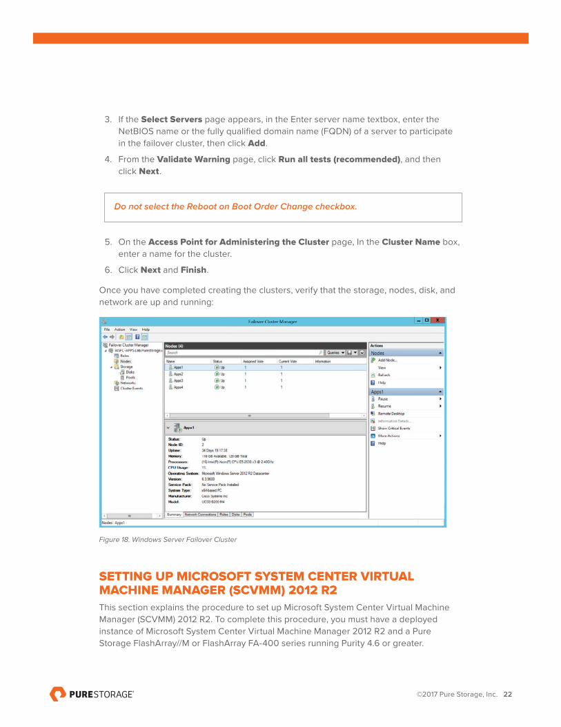
3. If the Select Servers page appears, in the Enter server name textbox, enter the NetBIOS name or the fully qualified domain name (FQDN) of a server to participate in the failover cluster, then click Add.
4. From the Validate Warning page, click Run all tests (recommended), and then click Next.
Do not select the Reboot on Boot Order Change checkbox.
5. On the Access Point for Administering the Cluster page, In the Cluster Name box, enter a name for the cluster.
6. Click Next and Finish.
Once you have completed creating the clusters, verify that the storage, nodes, disk, and network are up and running:
Figure 18. Windows Server Failover Cluster
SETTING UP MICROSOFT SYSTEM CENTER VIRTUAL MACHINE MANAGER (SCVMM) 2012 R2
This section explains the procedure to set up Microsoft System Center Virtual Machine Manager (SCVMM) 2012 R2. To complete this procedure, you must have a deployed instance of Microsoft System Center Virtual Machine Manager 2012 R2 and a Pure Storage FlashArray//M or FlashArray FA-400 series running Purity 4.6 or greater.
©2017 Pure Storage, Inc. 23
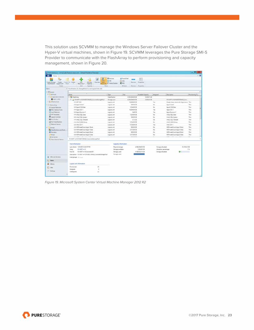
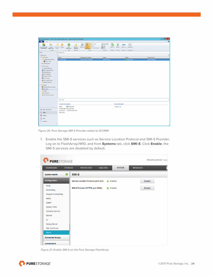
This solution uses SCVMM to manage the Windows Server Failover Cluster and the Hyper-V virtual machines, shown in Figure 19. SCVMM leverages the Pure Storage SMI-S Provider to communicate with the FlashArray to perform provisioning and capacity management, shown in Figure 20.
Figure 19. Microsoft System Center Virtual Machine Manager 2012 R2
©2017 Pure Storage, Inc. 24
Figure 20. Pure Storage SMI-S Provider added to SCVMM
1. Enable the SMI-S services such as Service Location Protocol and SMI-S Provider. Log on to FlashArray//M10, and from Systems tab, click SMI-S. Click Enable, the SMI-S services are disabled by default.
Figure 21. Enable SMI-S on the Pure Storage FlashArray
©2017 Pure Storage, Inc. 25
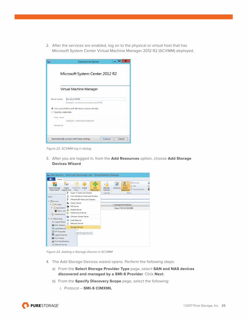
2. After the services are enabled, log on to the physical or virtual host that has Microsoft System Center Virtual Machine Manager 2012 R2 (SCVMM) deployed.
Figure 22. SCVMM log in dialog
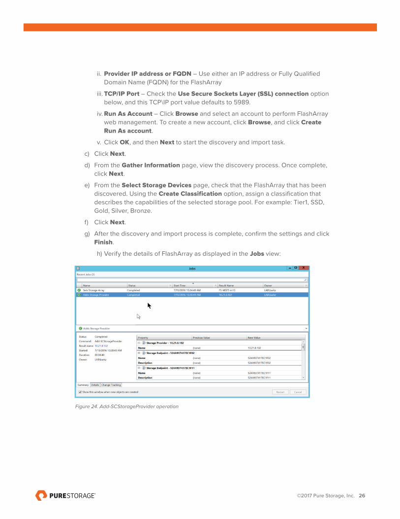
3. After you are logged in, from the Add Resources option, choose Add Storage
Devices Wizard.
Figure 23. Adding a Storage Device in SCVMM
4. The Add Storage Devices wizard opens. Perform the following steps:
a) From the Select Storage Provider Type page, select SAN and NAS devices
discovered and managed by a SMI-S Provider. Click Next.
b) From the Specify Discovery Scope page, select the following:
i. Protocol – SMI-S CIMXML
©2017 Pure Storage, Inc. 26
ii. Provider IP address or FQDN – Use either an IP address or Fully Qualified Domain Name (FQDN) for the FlashArray
iii. TCP/IP Port – Check the Use Secure Sockets Layer (SSL) connection option below, and this TCP\IP port value defaults to 5989.
iv. Run As Account – Click Browse and select an account to perform FlashArray web management. To create a new account, click Browse, and click Create Run As account.
v. Click OK, and then Next to start the discovery and import task.
c) Click Next.
d) From the Gather Information page, view the discovery process. Once complete, click Next.
e) From the Select Storage Devices page, check that the FlashArray that has been discovered. Using the Create Classification option, assign a classification that describes the capabilities of the selected storage pool. For example: Tier1, SSD, Gold, Silver, Bronze.
f) Click Next.
g) After the discovery and import process is complete, confirm the settings and click Finish.
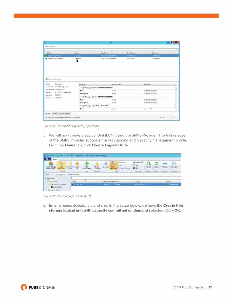
h) Verify the details of FlashArray as displayed in the Jobs view:
Figure 24. Add-SCStorageProvider operation
©2017 Pure Storage, Inc. 27
Figure 25. Set-SCStorageArray operation
5. We will now create a Logical Unit (LUN) using the SMI-S Provider. The first release of the SMI-S Provider supports the Provisioning and Capacity management profile. From the Home tab, click Create Logical Units.
Figure 26. Create Logical Unit (LUN)
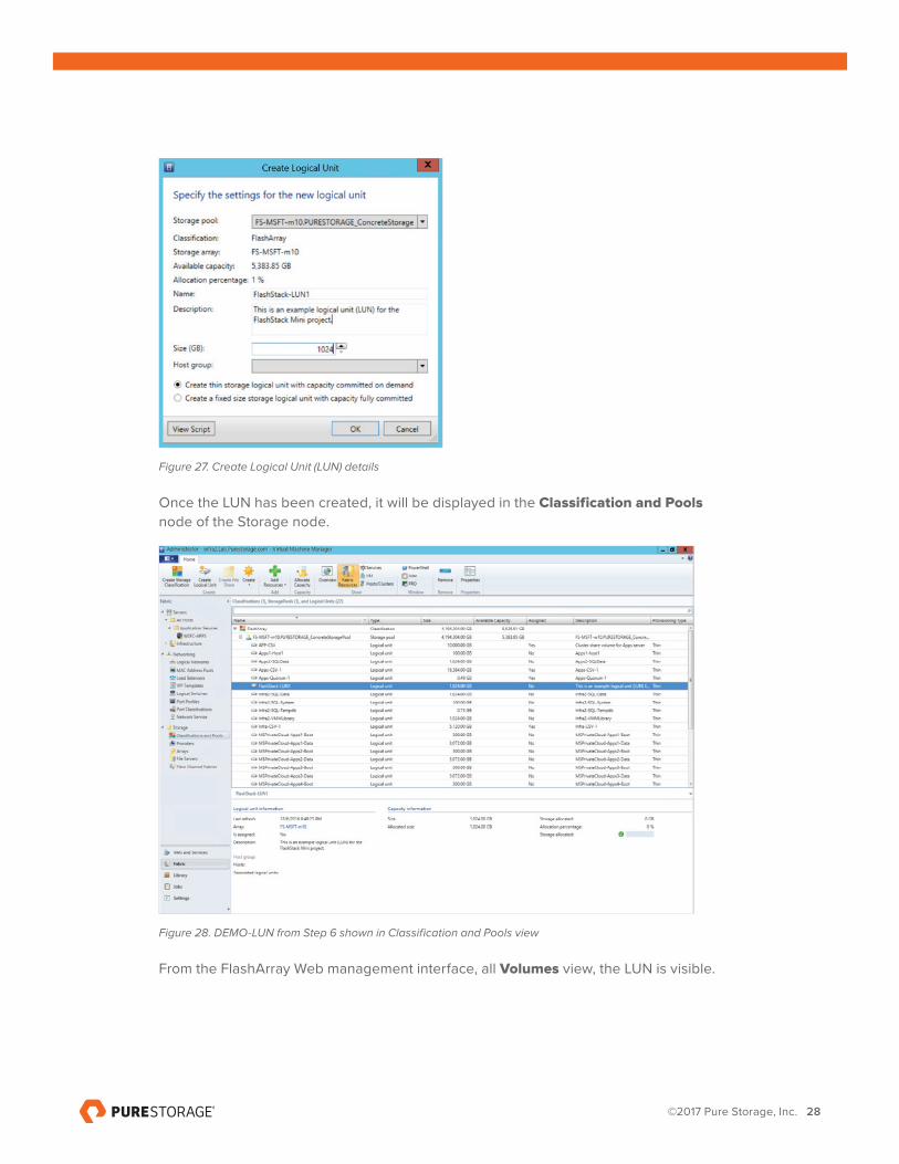
6. Enter a name, description, and size. In the setup below, we have the Create thin
storage logical unit with capacity committed on demand selected. Click OK.
©2017 Pure Storage, Inc. 28
Figure 27. Create Logical Unit (LUN) details
Once the LUN has been created, it will be displayed in the Classification and Pools node of the Storage node.
Figure 28. DEMO-LUN from Step 6 shown in Classification and Pools view
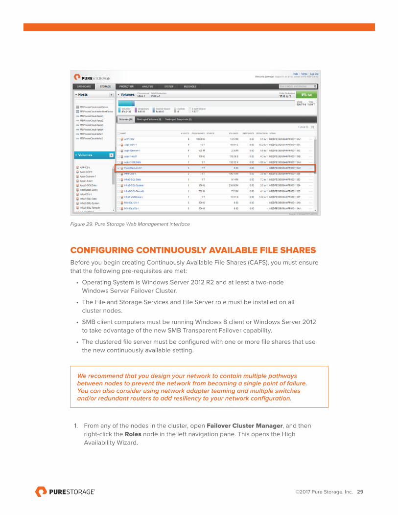
From the FlashArray Web management interface, all Volumes view, the LUN is visible.
©2017 Pure Storage, Inc. 29
Figure 29. Pure Storage Web Management interface
CONFIGURING CONTINUOUSLY AVAILABLE FILE SHARES Before you begin creating Continuously Available File Shares (CAFS), you must ensure that the following pre-requisites are met:
• Operating System is Windows Server 2012 R2 and at least a two-node Windows Server Failover Cluster.
• The File and Storage Services and File Server role must be installed on all cluster nodes.
• SMB client computers must be running Windows 8 client or Windows Server 2012 to take advantage of the new SMB Transparent Failover capability.
• The clustered file server must be configured with one or more file shares that use the new continuously available setting.
We recommend that you design your network to contain multiple pathways between nodes to prevent the network from becoming a single point of failure. You can also consider using network adapter teaming and multiple switches and/or redundant routers to add resiliency to your network configuration.
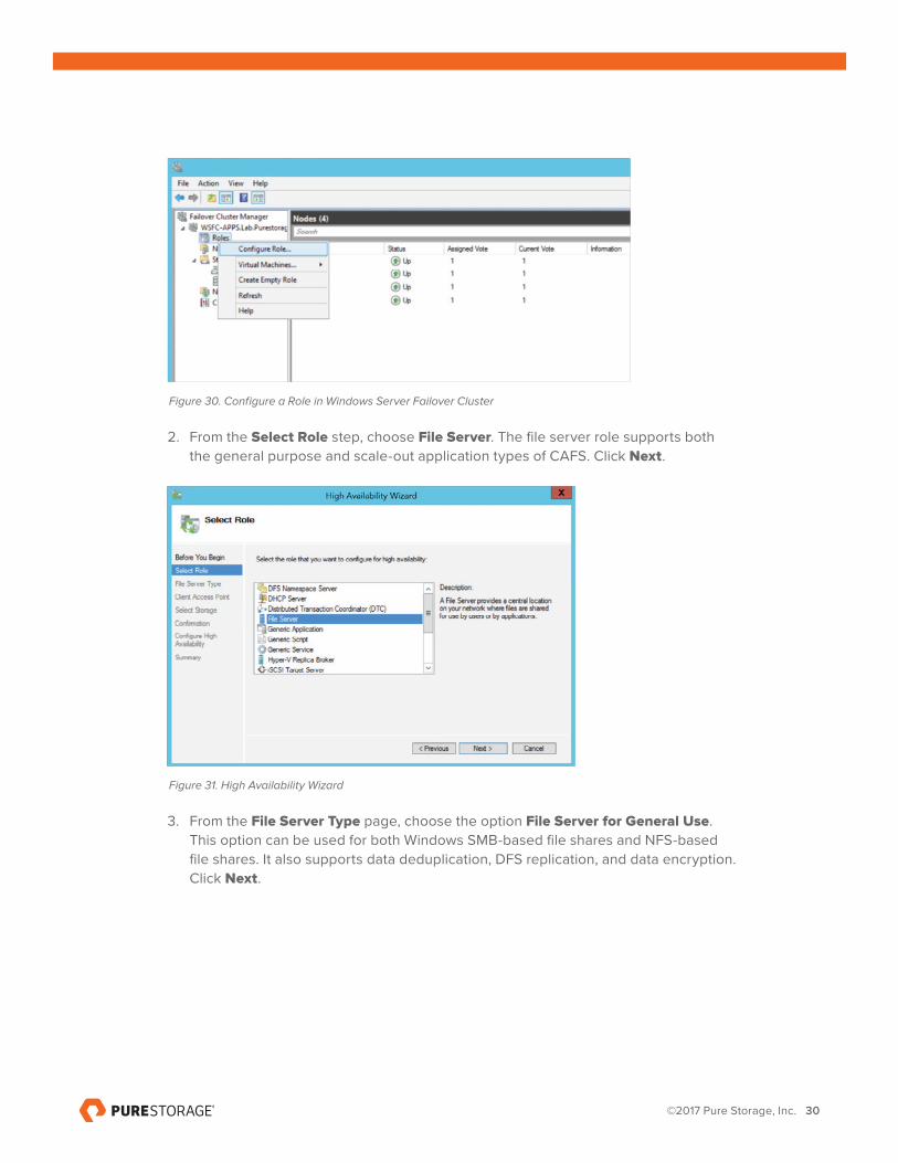
1. From any of the nodes in the cluster, open Failover Cluster Manager, and then right-click the Roles node in the left navigation pane. This opens the High Availability Wizard.
©2017 Pure Storage, Inc. 30
Figure 30. Configure a Role in Windows Server Failover Cluster
2. From the Select Role step, choose File Server. The file server role supports both the general purpose and scale-out application types of CAFS. Click Next.
Figure 31. High Availability Wizard
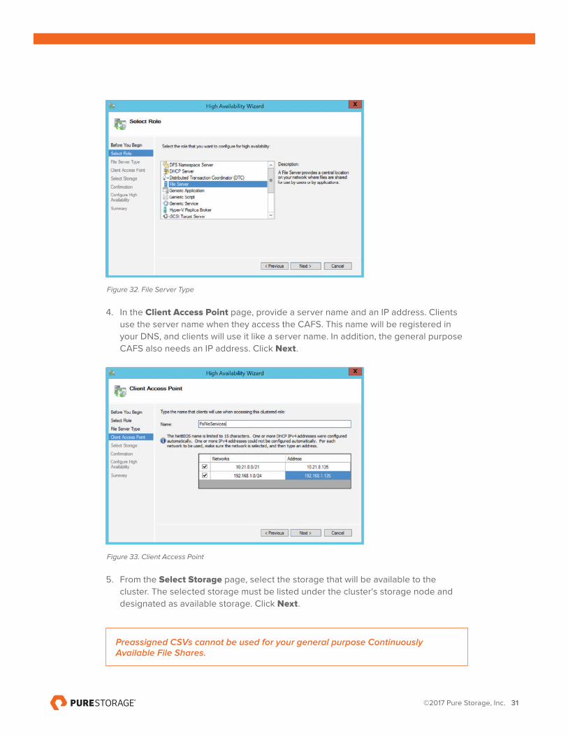
3. From the File Server Type page, choose the option File Server for General Use. This option can be used for both Windows SMB-based file shares and NFS-based file shares. It also supports data deduplication, DFS replication, and data encryption. Click Next.
©2017 Pure Storage, Inc. 31
Figure 32. File Server Type
4. In the Client Access Point page, provide a server name and an IP address. Clients use the server name when they access the CAFS. This name will be registered in your DNS, and clients will use it like a server name. In addition, the general purpose CAFS also needs an IP address. Click Next.
Figure 33. Client Access Point
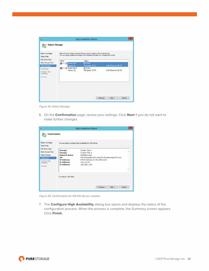
5. From the Select Storage page, select the storage that will be available to the cluster. The selected storage must be listed under the cluster's storage node and designated as available storage. Click Next.
Preassigned CSVs cannot be used for your general purpose Continuously Available File Shares.
©2017 Pure Storage, Inc. 32
Figure 34. Select Storage
6. On the Confirmation page, review your settings. Click Next if you do not want to make further changes.
Figure 35. Confirmation for HA File Server creation
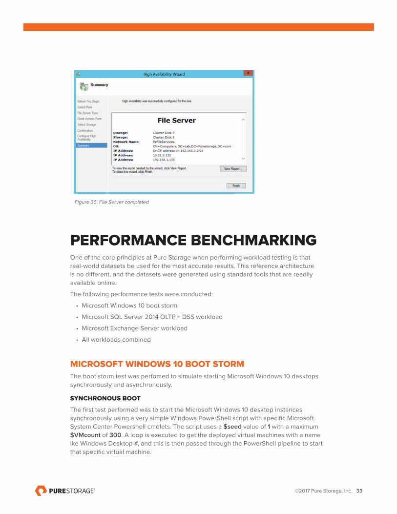
7. The Configure High Availability dialog box opens and displays the status of the configuration process. When the process is complete, the Summary screen appears. Click Finish.
©2017 Pure Storage, Inc. 33
Figure 36. File Server completed
PERFORMANCE BENCHMARKINGOne of the core principles at Pure Storage when performing workload testing is that real-world datasets be used for the most accurate results. This reference architecture is no different, and the datasets were generated using standard tools that are readily available online.
The following performance tests were conducted:
• Microsoft Windows 10 boot storm
• Microsoft SQL Server 2014 OLTP + DSS workload
• Microsoft Exchange Server workload
• All workloads combined
MICROSOFT WINDOWS 10 BOOT STORMThe boot storm test was perfomed to simulate starting Microsoft Windows 10 desktops synchronously and asynchronously.
SYNCHRONOUS BOOT
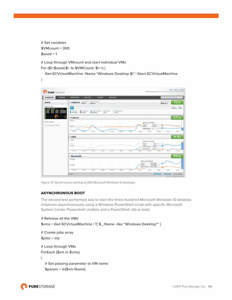
The first test performed was to start the Microsoft Windows 10 desktop instances synchronously using a very simple Windows PowerShell script with specific Microsoft System Center Powershell cmdlets. The script uses a $seed value of 1 with a maximum $VMcount of 300. A loop is executed to get the deployed virtual machines with a name lke Windows Desktop #, and this is then passed through the PowerShell pipeline to start that specific virtual machine.
©2017 Pure Storage, Inc. 34
# Set variables$VMcount = 300$seed = 1
# Loop through VMcount and start individual VMsFor ($i=$seed;$i -le $VMCount; $i++) { Get-SCVirtualMachine -Name "Windows Desktop $i" | Start-SCVirtualMachine}
Figure 37. Synchronous starting of 300 Microsoft Windows 10 desktops
ASYNCHRONOUS BOOT
The second test performed was to start the three-hundred Microsoft Windows 10 desktop instances asynchronously using a Windows PowerShell script with specific Microsoft System Center Powershell cmdlets and a PowerShell Job (a task).
# Retrieve all the VMs$vms = Get-SCVirtualMachine | ?{ $_.Name -like "Windows Desktop*" }
# Create jobs array$jobs = @()
# Loop through VMsForEach ($vm in $vms){ # Set passing parameter to VM name $param = @($vm.Name)
©2017 Pure Storage, Inc. 35
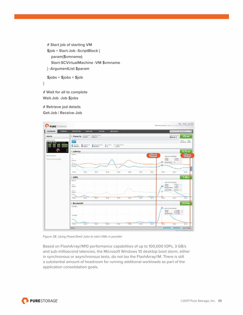
# Start job of starting VM $job = Start-Job -ScriptBlock { param($vmname) Start-SCVirtualMachine -VM $vmname } -ArgumentList $param
$jobs = $jobs + $job}
# Wait for all to completeWait-Job -Job $jobs
# Retrieve jod detailsGet-Job | Receive-Job
Figure 38. Using PowerShell Jobs to start VMs in parallel
Based on FlashArray//M10 performance capabilities of up to 100,000 IOPs, 3 GB/s and sub-millisecond latencies, the Microsoft Windows 10 desktop boot storm, either in synchronous or asynchronous tests, do not tax the FlashArray//M. There is still a substantial amount of headroom for running additional workloads as part of the application consolidation goals.
©2017 Pure Storage, Inc. 36
MICROSOFT SQL SERVER 2014 OLTP + DSS WORKLOADS
ONLINE TRANSACTION PROCESSING (OLTP)
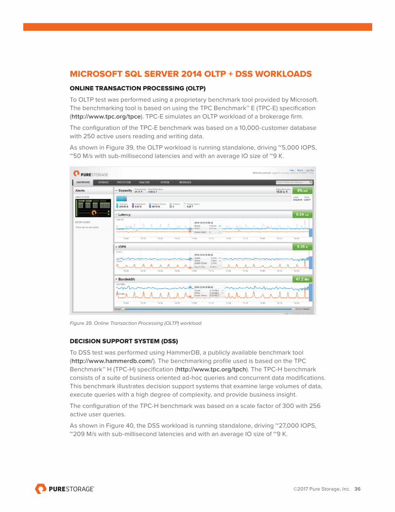
To OLTP test was performed using a proprietary benchmark tool provided by Microsoft. The benchmarking tool is based on using the TPC Benchmark™ E (TPC-E) specification (http://www.tpc.org/tpce). TPC-E simulates an OLTP workload of a brokerage firm.
The configuration of the TPC-E benchmark was based on a 10,000-customer database with 250 active users reading and writing data.
As shown in Figure 39, the OLTP workload is running standalone, driving ~5,000 IOPS, ~50 M/s with sub-millisecond latencies and with an average IO size of ~9 K.
Figure 39. Online Transaction Processing (OLTP) workload
DECISION SUPPORT SYSTEM (DSS)
To DSS test was performed using HammerDB, a publicly available benchmark tool (http://www.hammerdb.com/). The benchmarking profile used is based on the TPC Benchmark™ H (TPC-H) specification (http://www.tpc.org/tpch). The TPC-H benchmark consists of a suite of business oriented ad-hoc queries and concurrent data modifications. This benchmark illustrates decision support systems that examine large volumes of data, execute queries with a high degree of complexity, and provide business insight.
The configuration of the TPC-H benchmark was based on a scale factor of 300 with 256 active user queries.
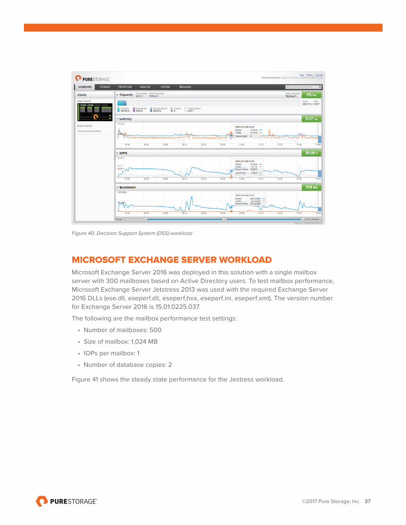
As shown in Figure 40, the DSS workload is running standalone, driving ~27,000 IOPS, ~209 M/s with sub-millisecond latencies and with an average IO size of ~9 K.
©2017 Pure Storage, Inc. 37
Figure 40. Decision Support System (DSS) workload
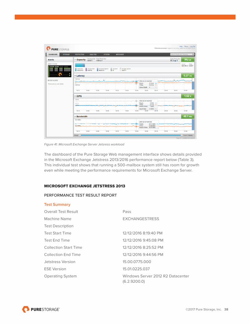
MICROSOFT EXCHANGE SERVER WORKLOADMicrosoft Exchange Server 2016 was deployed in this solution with a single mailbox server with 300 mailboxes based on Active Directory users. To test mailbox performance, Microsoft Exchange Server Jetstress 2013 was used with the required Exchange Server 2016 DLLs (ese.dll, eseperf.dll, eseperf,hxx, eseperf.ini, eseperf.xml). The version number for Exchange Server 2016 is 15.01.0225.037.
The following are the mailbox performance test settings:
• Number of mailboxes: 500
• Size of mailbox: 1,024 MB
• IOPs per mailbox: 1
• Number of database copies: 2
Figure 41 shows the steady state performance for the Jestress workload.
©2017 Pure Storage, Inc. 38
Figure 41. Microsoft Exchange Server Jetsress workload
The dashboard of the Pure Storage Web management interface shows details provided in the Microsoft Exchange Jetstress 2013/2016 performance report below (Table 3). This individual test shows that running a 500-mailbox system still has room for growth even while meeting the performance requirements for Microsoft Exchange Server.
MICROSOFT EXCHANGE JETSTRESS 2013
PERFORMANCE TEST RESULT REPORT
Test Summary
Overall Test Result Pass
Machine Name EXCHANGESTRESS
Test Description
Test Start Time 12/12/2016 8:19:40 PM
Test End Time 12/12/2016 9:45:08 PM
Collection Start Time 12/12/2016 8:25:52 PM
Collection End Time 12/12/2016 9:44:56 PM
Jetstress Version 15.00.0775.000
ESE Version 15.01.0225.037
Operating System Windows Server 2012 R2 Datacenter (6.2.9200.0)

©2017 Pure Storage, Inc. 39
Performance Log C:\Program Files\Exchange Jetstress\ Tuning_2016_12_12_20_20_21.blg
C:\Program Files\Exchange Jetstress\ Performance_2016_12_12_20_25_36.blg
Database Sizing and Throughput
Achieved Transactional I/O per Second 1214.197
Target Transactional I/O per Second 500
Initial Database Size (bytes) 1073760829440
Final Database Size (bytes) 1075606323200
Database Files (Count) 2
Jetstress System Parameters
Thread Count 1
Minimum Database Cache 64.0 MB
Maximum Database Cache 512.0 MB
Insert Operations 40%
Delete Operations 20%
Replace Operations 5%
Read Operations 35%
Lazy Commits 70%
Run Background Database Maintenance True
Number of Copies per Database 1
Database Configuration
Instance6068.1 Log path: E:\Log1
Database: E:\Db1\Jetstress001001.edb
Instance6068.2 Log path: E:\Log2
Database: E:\Db2\Jetstress002001.edb
©2017 Pure Storage, Inc. 40
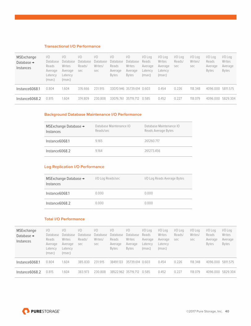
Transactional I/O Performance
Background Database Maintenance I/O Performance
MSExchange Database →
Instances
Database Maintenance IO Reads/sec
Database Maintenance IO Reads Average Bytes
Instance6068.1 9.165 261260.717
Instance6068.2 9.164 261273.456
Log Replication I/O Performance
MSExchange Database →
Instances
I/O Log Reads/sec I/O Log Reads Average Bytes
Instance6068.1 0.000 0.000
Instance6068.2 0.000 0.000
Total I/O Performance
MSExchange
Database →
Instances
I/O Database Reads Average Latency (msec)
I/O Database Writes Average Latency (msec)
I/O Database Reads/sec
I/O Database Writes/sec
I/O Database Reads Average Bytes
I/O Database Writes Average Bytes
I/O Log Reads Average Latency (msec)
I/O Log Writes Average Latency (msec)
I/O Log Reads/sec
I/O Log Writes/sec
I/O Log Reads Average Bytes
I/O Log Writes Average Bytes
Instance6068.1 0.804 1.604 376.666 231.915 33070.946 35739.614 0.603 0.454 0.226 118.348 4096.000 5811.575
Instance6068.2 0.815 1.604 374.809 230.808 33076.761 35719.712 0.585 0.452 0.227 118.079 4096.000 5829.304
MSExchange
Database →
Instances
I/O Database Reads Average Latency (msec)
I/O Database Writes Average Latency (msec)
I/O Database Reads/sec
I/O Database Writes/sec
I/O Database Reads Average Bytes
I/O Database Writes Average Bytes
I/O Log Reads Average Latency (msec)
I/O Log Writes Average Latency (msec)
I/O Log Reads/sec
I/O Log Writes/sec
I/O Log Reads Average Bytes
I/O Log Writes Average Bytes
Instance6068.1 0.804 1.604 385.830 231.915 38491.133 35739.614 0.603 0.454 0.226 118.348 4096.000 5811.575
Instance6068.2 0.815 1.604 383.973 230.808 38522.962 35719.712 0.585 0.452 0.227 118.079 4096.000 5829.304
©2017 Pure Storage, Inc. 41
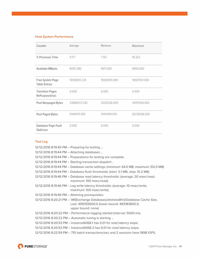
Host System Performance
Counter Average Minimum Maximum
% Processor Time 8.671 1.362 18.323
Available MBytes 6935.580 6911.000 6956.000
Free System Page
Table Entries
16506912.224 16506591.000 16507031.000
Transition Pages
RePurposed/sec
0.000 0.000 0.000
Pool Nonpaged Bytes 33686072.530 33251328.000 34197504.000
Pool Paged Bytes 93686515.886 93614080.000 93728768.000
Database Page Fault
Stalls/sec
0.000 0.000 0.000
Test Log
12/12/2016 8:19:40 PM – Preparing for testing ...12/12/2016 8:19:44 PM – Attaching databases ...12/12/2016 8:19:44 PM – Preparations for testing are complete.12/12/2016 8:19:44 PM – Starting transaction dispatch ..12/12/2016 8:19:44 PM – Database cache settings: (minimum: 64.0 MB, maximum: 512.0 MB)12/12/2016 8:19:44 PM – Database flush thresholds: (start: 5.1 MB, stop: 10.2 MB)12/12/2016 8:19:46 PM – Database read latency thresholds: (average: 20 msec/read,
maximum: 100 msec/read).12/12/2016 8:19:46 PM – Log write latency thresholds: (average: 10 msec/write,
maximum: 100 msec/write).12/12/2016 8:19:46 PM – Attaining prerequisites:12/12/2016 8:20:21 PM – \MSExchange Database(JetstressWin)\Database Cache Size,
Last: 499355600.0 (lower bound: 483183800.0, upper bound: none)
12/12/2016 8:20:22 PM – Performance logging started (interval: 5000 ms).12/12/2016 8:20:22 PM – Automatic tuning is starting ...12/12/2016 8:20:53 PM – Instance6068.1 has 0.01 for read latency slope.12/12/2016 8:20:53 PM – Instance6068.2 has 0.01 for read latency slope.12/12/2016 8:22:59 PM – 715 batch transactions/sec and 2 sessions have 1898 IOPS.

©2017 Pure Storage, Inc. 42
12/12/2016 8:22:59 PM – 2 sessions have actual 1898 IOPS (target IOPS: 500)12/12/2016 8:22:59 PM – Instance6068.1 has 0.9 for I/O Database Reads
Average Latency.12/12/2016 8:22:59 PM – Instance6068.2 has 0.9 for I/O Database Reads
Average Latency.12/12/2016 8:22:59 PM – Instance6068.1 has 0.4 for I/O Log Writes Average Latency.12/12/2016 8:22:59 PM – Instance6068.1 has 0.3 for I/O Log Reads Average Latency.12/12/2016 8:22:59 PM – Instance6068.2 has 0.4 for I/O Log Writes Average Latency.12/12/2016 8:22:59 PM – Instance6068.2 has 0.2 for I/O Log Reads Average Latency.12/12/2016 8:22:59 PM – Operation mix: Sessions 1, Inserts 40%, Deletes 20%,
Replaces 5%, Reads 35%, Lazy Commits 70%.12/12/2016 8:23:30 PM – Instance6068.1 has 0.00 for read latency slope.12/12/2016 8:23:30 PM – Instance6068.2 has 0.00 for read latency slope.12/12/2016 8:25:36 PM – 430 batch transactions/sec and 1 sessions have 1189 IOPS.12/12/2016 8:25:36 PM – 1 sessions have actual 1189 IOPS (target IOPS: 500)12/12/2016 8:25:36 PM – Instance6068.1 has 0.8 for I/O Database Reads
Average Latency.12/12/2016 8:25:36 PM – Instance6068.2 has 0.8 for I/O Database Reads
Average Latency.12/12/2016 8:25:36 PM – Instance6068.1 has 0.4 for I/O Log Writes Average Latency.12/12/2016 8:25:36 PM – Instance6068.1 has 0.2 for I/O Log Reads Average Latency.12/12/2016 8:25:36 PM – Instance6068.2 has 0.4 for I/O Log Writes Average Latency.12/12/2016 8:25:36 PM – Instance6068.2 has 0.1 for I/O Log Reads Average Latency.12/12/2016 8:25:36 PM – Performance logging has ended.12/12/2016 8:25:36 PM – Automatic tuning succeeded.12/12/2016 8:25:37 PM – Operation mix: Sessions 1, Inserts 40%, Deletes 20%,
Replaces 5%, Reads 35%, Lazy Commits 70%.12/12/2016 8:25:37 PM – Performance logging started (interval: 15000 ms).12/12/2016 8:25:37 PM – Attaining prerequisites:12/12/2016 8:25:37 PM – \MSExchange Database(JetstressWin)\Database Cache Size,
Last: 528072700.0 (lower bound: 483183800.0, upper bound: none)
12/12/2016 9:45:07 PM – Performance logging has ended.12/12/2016 9:45:07 PM – JetInterop batch transaction stats: 66545 and 66544.12/12/2016 9:45:07 PM – Dispatching transactions ends.12/12/2016 9:45:07 PM – Shutting down databases ...12/12/2016 9:45:08 PM – Instance6068.1 (complete) and Instance6068.2 (complete)12/12/2016 9:45:08 PM – C:\Program Files\Exchange Jetstress\
Performance_2016_12_12_20_25_36.blg has 317 samples.12/12/2016 9:45:08 PM – Creating test report ...12/12/2016 9:45:09 PM – Instance6068.1 has 0.8 for I/O Database Reads
Average Latency.

©2017 Pure Storage, Inc. 43
12/12/2016 9:45:09 PM – Instance6068.1 has 0.5 for I/O Log Writes Average Latency.12/12/2016 9:45:09 PM – Instance6068.1 has 0.5 for I/O Log Reads Average Latency.12/12/2016 9:45:09 PM – Instance6068.2 has 0.8 for I/O Database Reads
Average Latency.12/12/2016 9:45:09 PM – Instance6068.2 has 0.5 for I/O Log Writes Average Latency.12/12/2016 9:45:09 PM – Instance6068.2 has 0.5 for I/O Log Reads Average Latency.12/12/2016 9:45:09 PM – Test has 0 Maximum Database Page Fault Stalls/sec.12/12/2016 9:45:09 PM – The test has 0 Database Page Fault Stalls/sec samples
higher than 0.12/12/2016 9:45:09 PM – C:\Program Files\Exchange Jetstress\
Performance_2016_12_12_20_25_36.xml has 316 samples queried.
Table 3. Microsoft Exchange Jetstress performance results
ALL WORKLOADS COMBINEDAll of the workloads mentioned at the beginning of this section were run to show their performance individually. This final test is to run all of the workloads concurrently to illustrate combined performance. As Figure 42 illustrates, all of the workloads are running with sub-millisecond latency, ~30,000 IOPS and a burst of ~2 G/s with an average Bandwidth running in the ~500 M/s range. The FlashArray//M10 still has room for additional server workloads or virtual machines.
Figure 42. All SQL Server, Exchange Server, SharePoint workloads running and VM boot storm
©2017 Pure Storage, Inc. 44
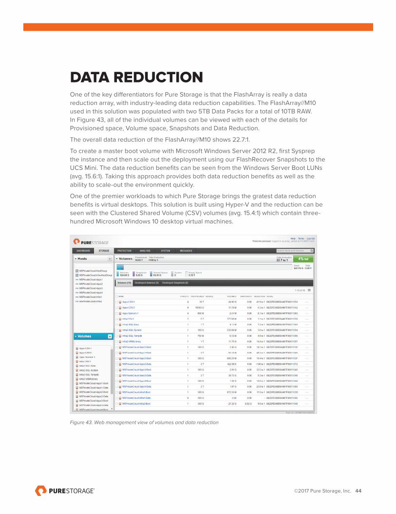
DATA REDUCTIONOne of the key differentiators for Pure Storage is that the FlashArray is really a data reduction array, with industry-leading data reduction capabilities. The FlashArray//M10 used in this solution was populated with two 5TB Data Packs for a total of 10TB RAW. In Figure 43, all of the individual volumes can be viewed with each of the details for Provisioned space, Volume space, Snapshots and Data Reduction.
The overall data reduction of the FlashArray//M10 shows 22.7:1.
To create a master boot volume with Microsoft Windows Server 2012 R2, first Sysprep the instance and then scale out the deployment using our FlashRecover Snapshots to the UCS Mini. The data reduction benefits can be seen from the Windows Server Boot LUNs (avg. 15.6:1). Taking this approach provides both data reduction benefits as well as the ability to scale-out the environment quickly.
One of the premier workloads to which Pure Storage brings the gratest data reduction benefits is virtual desktops. This solution is built using Hyper-V and the reduction can be seen with the Clustered Shared Volume (CSV) volumes (avg. 15.4:1) which contain three-hundred Microsoft Windows 10 desktop virtual machines.
Figure 43. Web management view of volumes and data reduction
©2017 Pure Storage, Inc. 45
CONCLUSIONAgility, reliability, performance, and management are just some of the core bulletpoints that IT managers and administrators require in the data center. Using FlashStack for Converged Infrastructure with Cisco UCS Mini™ and Pure Storage FlashArray//M provides a compute, networking, and storage platform that provides all of the core bulletpoints mentioned along with the ability to scale and grow as business demands require.
Excellent performance, with sub-millisecond latency, overall data reduction for all combined workloads, and core infrastructure showcases the versatility of this FlashStack CI solution. Factors like service profiles, rapid deployment, ease of storage management, lower storage cost, lower power, rack space savings, and lower cooling requirements make the TCO for large scale deployments even more attractive.
©2017 Pure Storage, Inc. 46
APPENDIX 1: PURE STORAGE COMPONENTS IN FLASHSTACKThis section provides a detailed description for each infrastructure component of FlashStack Mini.
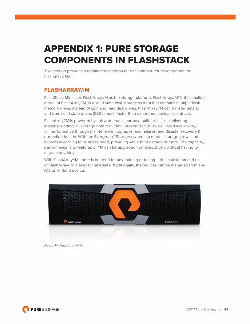
FLASHARRAY//M FlashStack Mini uses FlashArray//M as the storage platform. FlashArray//M10, the smallest model of FlashArray//M, is a solid state disk storage system that contains multiple flash memory drives instead of spinning hard disk drives. FlashArray//M can transfer data to and from solid state drives (SSDs) much faster than electromechanical disk drives.
FlashArray//M is powered by software that is purpose built for flash – delivering industry-leading 5:1 average data reduction, proven 99.9999% delivered availability, full performance through maintenance, upgrades, and failures, and disaster recovery & protection built-in. With the Evergreen™ Storage ownership model, storage grows and evolves according to business need, providing value for a decade or more. The capacity, performance, and features of //M can be upgraded non-disruptively without having to migrate anything.
With FlashArray//M, there is no need for any training or tuning – the installation and use of FlashArray//M is almost immediate. Additionally, the devices can be managed from any iOS or Android device.
Figure 44. FlashArray//M10
©2017 Pure Storage, Inc. 47
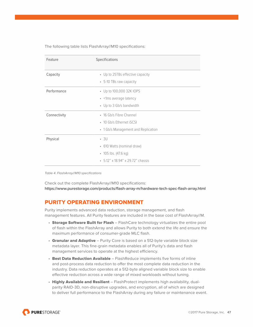
The following table lists FlashArray//M10 specifications:
Feature Specifications
Capacity • Up to 25TBs effective capacity
• 5-10 TBs raw capacity
Performance • Up to 100,000 32K IOPS
• <1ms average latency
• Up to 3 Gb/s bandwidth
Connectivity • 16 Gb/s Fibre Channel
• 10 Gb/s Ethernet iSCSI
• 1 Gb/s Management and Replication
Physical • 3U
• 610 Watts (nominal draw)
• 105 lbs. (47.6 kg)
• 5.12” x 18.94” x 29.72” chassis
Table 4. FlashArray//M10 specifications
Check out the complete FlashArray//M10 specifications: https://www.purestorage.com/products/flash-array-m/hardware-tech-spec-flash-array.html
PURITY OPERATING ENVIRONMENT Purity implements advanced data reduction, storage management, and flash management features. All Purity features are included in the base cost of FlashArray//M.
• Storage Software Built for Flash – FlashCare technology virtualizes the entire pool of flash within the FlashArray and allows Purity to both extend the life and ensure the maximum performance of consumer-grade MLC flash.
• Granular and Adaptive – Purity Core is based on a 512-byte variable block size metadata layer. This fine-grain metadata enables all of Purity’s data and flash management services to operate at the highest efficiency.
• Best Data Reduction Available – FlashReduce implements five forms of inline and post-process data reduction to offer the most complete data reduction in the industry. Data reduction operates at a 512-byte aligned variable block size to enable effective reduction across a wide range of mixed workloads without tuning.
• Highly Available and Resilient – FlashProtect implements high availability, dual-parity RAID-3D, non-disruptive upgrades, and encryption, all of which are designed to deliver full performance to the FlashArray during any failure or maintenance event.
©2017 Pure Storage, Inc. 48
• Backup and Disaster Recovery Built In – FlashRecover combines space-saving snapshots, replication, and protection policies into an end-to-end data protection and recovery solution that protects data against loss locally and globally. All FlashProtect services are fully-integrated in the FlashArray and leverage native data reduction capabilities.
PURE1® – COMPONENT FEATURES• Pure1 Manage – Combining local web-based management with cloud-based
monitoring, Pure1 Manage allows you to manage your FlashArray wherever you are – with just a web browser or a smartphone mobile app.
• Pure1 Connect – A rich set of APIs, plugin-is, application connectors, and automation toolkits enable you to connect FlashArray//M to all your data center and cloud monitoring, management, and orchestration tools.
• Pure1 Support – FlashArray//M is constantly cloud-connected, enabling Pure Storage to deliver the most proactive support experience possible. Highly trained staff combined with big data analytics help resolve problems before they occur.
• Pure1 Collaborate – Extend your development and support experience online, leveraging the Pure1 Collaborate community to get peer-based support and to share tips, tricks, and scripts.
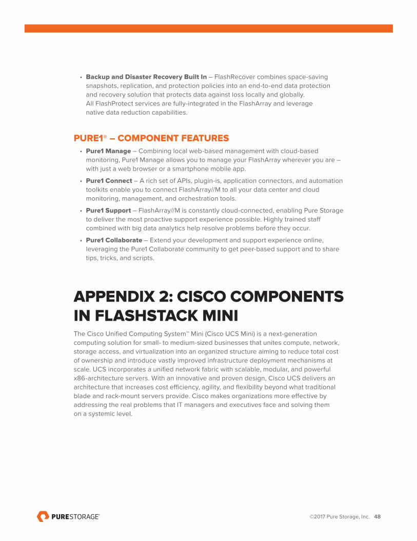
APPENDIX 2: CISCO COMPONENTS IN FLASHSTACK MINIThe Cisco Unified Computing System™ Mini (Cisco UCS Mini) is a next-generation computing solution for small- to medium-sized businesses that unites compute, network, storage access, and virtualization into an organized structure aiming to reduce total cost of ownership and introduce vastly improved infrastructure deployment mechanisms at scale. UCS incorporates a unified network fabric with scalable, modular, and powerful x86-architecture servers. With an innovative and proven design, Cisco UCS delivers an architecture that increases cost efficiency, agility, and flexibility beyond what traditional blade and rack-mount servers provide. Cisco makes organizations more effective by addressing the real problems that IT managers and executives face and solving them on a systemic level.
©2017 Pure Storage, Inc. 49
Figure 45. Cisco Unified Computing System
GREATER TIME-ON-TASK EFFICIENCY
Automated configuration can change an IT organization’s approach from reactive to proactive. The result is more time for innovation, less time spent on maintenance, and faster response times. These efficiencies allow IT staff more time to address strategic business initiatives. They also enable better quality of life for IT staff, which means higher morale and better staff retention – both critical elements for long-term efficiency.
Cisco UCS Manager is an embedded, model-based management system that allows IT administrators to set a vast range of server configuration policies, from firmware and BIOS settings to network and storage connectivity. Individual servers can be deployed in less time and with fewer steps than in traditional environments. Automation frees staff from tedious, repetitive, time-consuming chores that are often the source of errors that cause downtime, making the entire data center more cost effective.
EASIER SCALING
Automation means rapid deployment, reduced opportunity cost, and better capital resource utilization. With Cisco UCS, rack-mount and blade servers can move from the loading dock and into production in a “plug-and-play” operation. Automatically configure blade servers using predefined policies simply by inserting the devices into an open blade chassis slot. Integrate rack-mount servers by connecting them to top-of-rack Cisco Nexus® fabric extenders. Since policies make configuration automated and repeatable, configuring 100 new servers is as straightforward as configuring one server, delivering agile, cost-effective scaling.
VIRTUAL BLADE CHASSIS
With a separate network and separate management for each chassis, traditional blade systems are functionally an accidental architecture based on an approach that compresses all the components of a rack into each and every chassis. Such traditional blade systems are managed with multiple management tools that are combined to give the illusion of convergence for what is ultimately a more labor-intensive, error-prone, and costly delivery methodology. Rack-mount servers are not integrated and must be
©2017 Pure Storage, Inc. 50
managed separately or through additional tool sets, adding complexity, overhead, and the burden of more time.
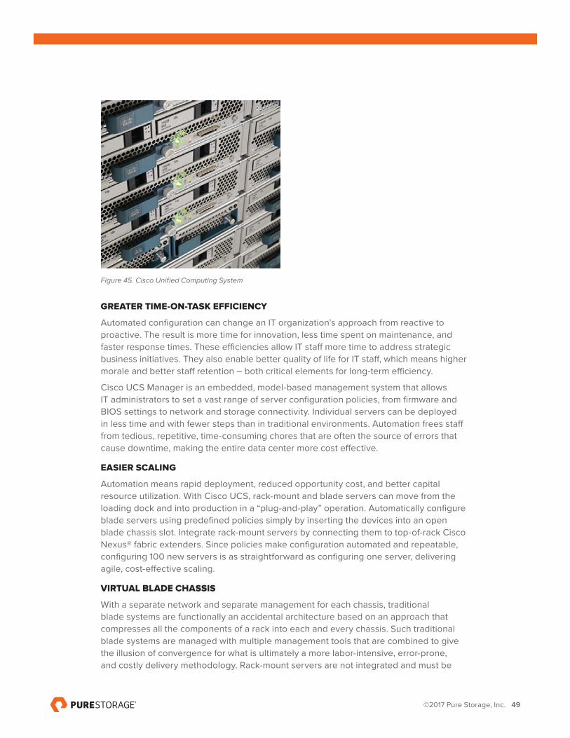
CISCO UCS 5108 CHASSISThe Cisco UCS Mini chassis is a 6RU chassis that can accommodate up to 8 half-width blades. The chassis is a Cisco UCS 5108 Blade Server chassis that allows the two I/O bays at the rear of the chassis to accommodate Fabric Extenders such as the UCS 2208XP or the UCS 6324 Fabric Interconnect modules. Cisco UCS Mini works on the Intel Xeon processor E5-2600, with up to 36 CPU processors of 1.5 TB memory.
Having a unified fabric reduces the number of network interface cards (NICs), hosted bus adapters (HBAs), switches, and cables needed. Cisco UCS 5108 also offers support for one or two Cisco UCS 2100 Series or Cisco UCS 2200 I/O modules, which helps lower the number of switches in the chassis and allows for a less complex configuration.
Figure 46. Cisco UCS 5108 Chassis
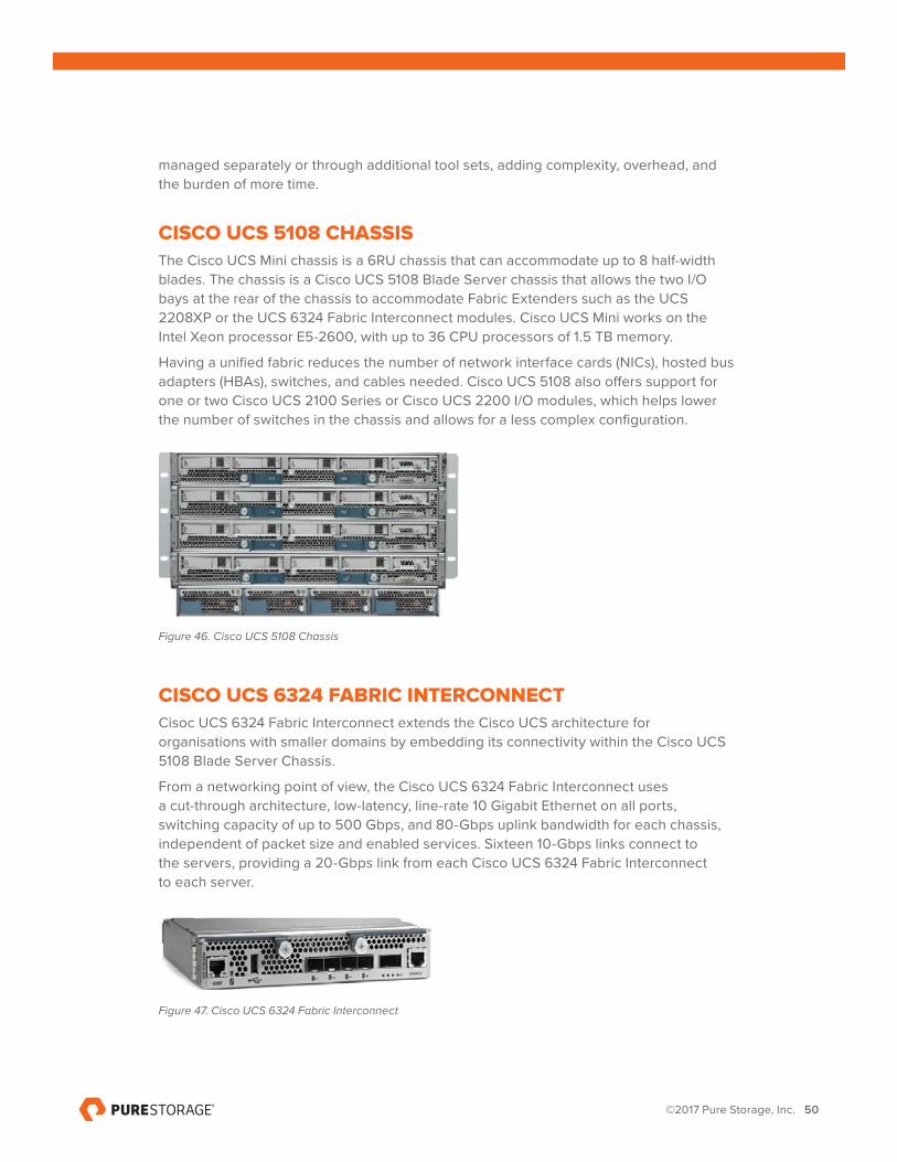
CISCO UCS 6324 FABRIC INTERCONNECTCisoc UCS 6324 Fabric Interconnect extends the Cisco UCS architecture for organisations with smaller domains by embedding its connectivity within the Cisco UCS 5108 Blade Server Chassis.
From a networking point of view, the Cisco UCS 6324 Fabric Interconnect uses a cut-through architecture, low-latency, line-rate 10 Gigabit Ethernet on all ports, switching capacity of up to 500 Gbps, and 80-Gbps uplink bandwidth for each chassis, independent of packet size and enabled services. Sixteen 10-Gbps links connect to the servers, providing a 20-Gbps link from each Cisco UCS 6324 Fabric Interconnect to each server.
Figure 47. Cisco UCS 6324 Fabric Interconnect
©2017 Pure Storage, Inc. 51
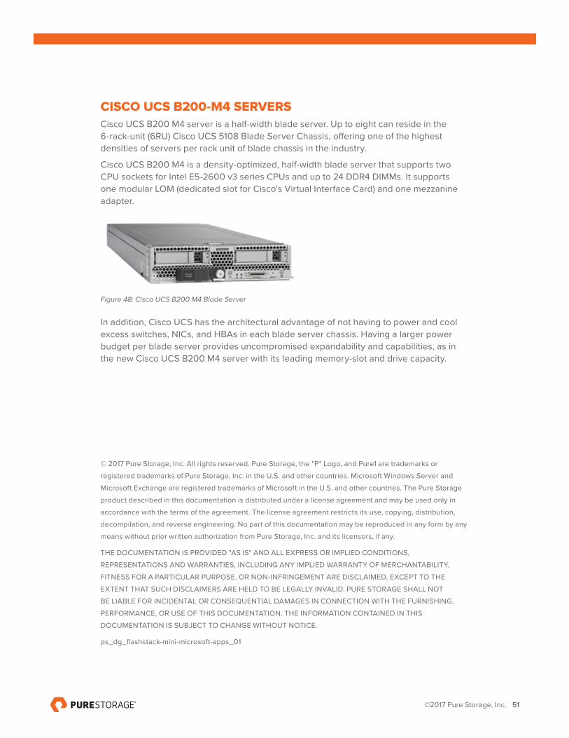
CISCO UCS B200-M4 SERVERSCisco UCS B200 M4 server is a half-width blade server. Up to eight can reside in the 6-rack-unit (6RU) Cisco UCS 5108 Blade Server Chassis, offering one of the highest densities of servers per rack unit of blade chassis in the industry.
Cisco UCS B200 M4 is a density-optimized, half-width blade server that supports two CPU sockets for Intel E5-2600 v3 series CPUs and up to 24 DDR4 DIMMs. It supports one modular LOM (dedicated slot for Cisco's Virtual Interface Card) and one mezzanine adapter.
Figure 48: Cisco UCS B200 M4 Blade Server
In addition, Cisco UCS has the architectural advantage of not having to power and cool excess switches, NICs, and HBAs in each blade server chassis. Having a larger power budget per blade server provides uncompromised expandability and capabilities, as in the new Cisco UCS B200 M4 server with its leading memory-slot and drive capacity.
© 2017 Pure Storage, Inc. All rights reserved. Pure Storage, the "P" Logo, and Pure1 are trademarks or
registered trademarks of Pure Storage, Inc. in the U.S. and other countries. Microsoft Windows Server and
Microsoft Exchange are registered trademarks of Microsoft in the U.S. and other countries. The Pure Storage
product described in this documentation is distributed under a license agreement and may be used only in
accordance with the terms of the agreement. The license agreement restricts its use, copying, distribution,
decompilation, and reverse engineering. No part of this documentation may be reproduced in any form by any
means without prior written authorization from Pure Storage, Inc. and its licensors, if any.
THE DOCUMENTATION IS PROVIDED "AS IS" AND ALL EXPRESS OR IMPLIED CONDITIONS,
REPRESENTATIONS AND WARRANTIES, INCLUDING ANY IMPLIED WARRANTY OF MERCHANTABILITY,
FITNESS FOR A PARTICULAR PURPOSE, OR NON-INFRINGEMENT ARE DISCLAIMED, EXCEPT TO THE
EXTENT THAT SUCH DISCLAIMERS ARE HELD TO BE LEGALLY INVALID. PURE STORAGE SHALL NOT
BE LIABLE FOR INCIDENTAL OR CONSEQUENTIAL DAMAGES IN CONNECTION WITH THE FURNISHING,
PERFORMANCE, OR USE OF THIS DOCUMENTATION. THE INFORMATION CONTAINED IN THIS
DOCUMENTATION IS SUBJECT TO CHANGE WITHOUT NOTICE.
ps_dg_flashstack-mini-microsoft-apps_01
©2017 Pure Storage, Inc. 52
Pure Storage, Inc.
Twitter: @purestorage
www.purestorage.com
650 Castro Street, Suite #260
Mountain View, CA 94041
T: 650-290-6088
F: 650-625-9667
Sales: [email protected]