flashsystem 840: installation guide - ibm · pdf filexii flashsystem 840: installation guide....
TRANSCRIPT
IBM FlashSystem 840
Installation Guide
GI13-2871-01
���

NoteBefore using this information and the product it supports, read the following information:
v The general information in “Notices” on page 51
v The information in the “Safety and environmental notices” on page ix
v The information in the IBM Environmental Notices and User Guide (provided on a DVD)
This edition applies to IBM FlashSystem 840 and to all subsequent releases and modifications until otherwiseindicated in new editions.
© Copyright IBM Corporation 2014, .US Government Users Restricted Rights – Use, duplication or disclosure restricted by GSA ADP Schedule Contractwith IBM Corp.

Contents
Figures . . . . . . . . . . . . . . . v
Tables . . . . . . . . . . . . . . . vii
Safety and environmental notices . . . ixSafety notices and labels . . . . . . . . . . ix
Caution notices . . . . . . . . . . . . xDanger notices . . . . . . . . . . . . xiii
Special caution and safety notices. . . . . . . xviHandling static-sensitive devices . . . . . . xviSound pressure . . . . . . . . . . . xvii
Environmental notices . . . . . . . . . . xvii
About this guide . . . . . . . . . . xixIBM FlashSystem 840 library and relatedpublications . . . . . . . . . . . . . . xixRelated websites . . . . . . . . . . . . xxiiHow to get information, help, and technicalassistance . . . . . . . . . . . . . . xxii
Chapter 1. Planning. . . . . . . . . . 1Planning. . . . . . . . . . . . . . . . 1
Planning for hardware . . . . . . . . . . 1Checking your web browser settings for themanagement GUI. . . . . . . . . . . . 6
Chapter 2. Installing the hardware . . . 9Before you begin the installation. . . . . . . . 9Reviewing your packaging slip . . . . . . . . 11Installing the hardware . . . . . . . . . . 12
Installing the support rails for the storageenclosure . . . . . . . . . . . . . . 12Installing the enclosure in a rack . . . . . . 16Connecting the management port Ethernet cables 20Connecting Fibre Channel, FCoE, or InfiniBandcables . . . . . . . . . . . . . . . 22Connecting the power cords . . . . . . . . 24
Chapter 3. Initializing the storageenclosure . . . . . . . . . . . . . 29Initializing a storage enclosure with an encryptionlicense . . . . . . . . . . . . . . . . 29
Initializing the storage enclosure with a MicrosoftWindows computer. . . . . . . . . . . 29Initializing the storage enclosure with a Linuxcomputer . . . . . . . . . . . . . . 31Initializing the storage enclosure with an AppleMacintosh computer . . . . . . . . . . 34
Initializing a storage enclosure without anencryption license . . . . . . . . . . . . 36
Initializing the storage enclosure with a MicrosoftWindows computer. . . . . . . . . . . 37Initializing the storage enclosure with a Linuxcomputer . . . . . . . . . . . . . . 39Initializing the storage enclosure with an AppleMacintosh computer . . . . . . . . . . 40
Chapter 4. Upgrading the storageenclosure hardware . . . . . . . . . 43Installing additional flash modules . . . . . . 43Adding additional SFPs . . . . . . . . . . 45
Appendix A. Accessibility features forIBM FlashSystem 840 . . . . . . . . 47
Appendix B. Where to find theStatement of Limited Warranty . . . . 49
Notices . . . . . . . . . . . . . . 51Trademarks . . . . . . . . . . . . . . 53
Index . . . . . . . . . . . . . . . 55
© Copyright IBM Corp. 2014, iii

iv FlashSystem 840: Installation Guide

Figures
1. Rack mounting rails and screws. . . . . . 122. Installing the rail spring . . . . . . . . 133. Hole locations in the front of the rack . . . . 144. Opening the hinge brackets . . . . . . . 155. Closing hinge brackets and installing rear
screw . . . . . . . . . . . . . . 166. Inserting the enclosure . . . . . . . . . 207. Management port connectors. . . . . . . 228. Interface cards . . . . . . . . . . . 249. Power connector location . . . . . . . . 26
10. Canister LEDs. . . . . . . . . . . . 2611. USB ports . . . . . . . . . . . . . 30
12. Status and identify LEDs . . . . . . . . 3013. USB ports . . . . . . . . . . . . . 3314. Status and identify LEDs . . . . . . . . 3315. USB ports . . . . . . . . . . . . . 3516. Status and identify LEDs . . . . . . . . 3517. USB ports . . . . . . . . . . . . . 3818. Status and identify LEDs . . . . . . . . 3819. USB ports . . . . . . . . . . . . . 4020. Status and identify LEDs . . . . . . . . 4021. USB ports . . . . . . . . . . . . . 4222. Status and identify LEDs . . . . . . . . 4223. Flash module . . . . . . . . . . . . 44
© Copyright IBM Corp. 2014, v

vi FlashSystem 840: Installation Guide

Tables
1. IBM websites for help, services, andinformation . . . . . . . . . . . . xix
2. IBM FlashSystem 840 library . . . . . . xix3. Publications for other IBM FlashSystem
products . . . . . . . . . . . . . xx4. IBM documentation and related websites xxi5. IBM websites for help, services, and
information . . . . . . . . . . . . xxii6. Enclosure management port Ethernet
connections . . . . . . . . . . . . . 1
7. IP addresses for the storage enclosure . . . . 18. Fibre Channel port connections . . . . . . 29. FCoE port connections . . . . . . . . . 3
10. InfiniBand port connections . . . . . . . 311. Switch Information . . . . . . . . . . 412. Management IP address configuration . . . . 413. Service IP address configuration . . . . . . 514. Event notification settings . . . . . . . . 515. TCP/IP ports and services listing . . . . . 516. Supported flash module configurations 43
© Copyright IBM Corp. 2014, vii

viii FlashSystem 840: Installation Guide

Safety and environmental notices
Suitability for telecommunication environment: This product is not intended toconnect directly or indirectly by any means whatsoever to interfaces of publictelecommunications networks.
Here are examples of a caution and a danger notice:
CAUTION:A caution notice indicates the presence of a hazard that has the potential ofcausing moderate or minor personal injury. (C001)
DANGER
A danger notice indicates the presence of a hazard that has the potential ofcausing death or serious personal injury. (D002)
To find the translated text for a caution or danger notice:1. Look for the identification number at the end of each caution notice or each
danger notice. In the preceding examples, the numbers (C001) and (D002) arethe identification numbers.
2. Locate the IBM Systems Safety Notices with the user publications that wereprovided with the hardware.
3. Find the matching identification number in the IBM Systems Safety Notices. Thenreview the topics concerning the safety notices to ensure that you are incompliance.
Safety notices and labelsReview the safety notices and safety information labels before using this product.
To view a PDF file, you need Adobe Acrobat Reader. You can download it at nocharge from the Adobe website:
www.adobe.com/support/downloads/main.html
IBM® Systems Safety Notices
This publication contains the safety notices for the IBM Systems products inEnglish and other languages. Anyone who plans, installs, operates, or services thesystem must be familiar with and understand the safety notices. Read the relatedsafety notices before you begin work.
Note: The IBM Systems Safety Notices document is organized into two sections.The danger and caution notices without labels are organized alphabetically bylanguage in the “Danger and caution notices by language” section. The danger andcaution notices that are accompanied with a label are organized by label referencenumber in the “Labels” section.
The following notices and statements are used in IBM documents. They are listedin order of decreasing severity of potential hazards.
© Copyright IBM Corp. 2014, ix

Danger notice definitionA special note that emphasize a situation that is potentially lethal orextremely hazardous to people.
Caution notice definitionA special note that emphasize a situation that is potentially hazardous topeople because of some existing condition, or to a potentially dangeroussituation that might develop because of some unsafe practice.
Note: In addition to these notices, labels might be attached to the product to warnof potential hazards.
Finding translated notices
Each safety notice contains an identification number. You can use this identificationnumber to check the safety notice in each language.
To find the translated text for a caution or danger notice:1. In the product documentation, look for the identification number at the end of
each caution notice or each danger notice. In the following examples, thenumbers (D002) and (C001) are the identification numbers.DANGER
A danger notice indicates the presence of a hazard that has the potentialof causing death or serious personal injury. (D002)
CAUTION:A caution notice indicates the presence of a hazard that has the potential ofcausing moderate or minor personal injury. (C001)
2. Open the IBM Systems Safety Notices.3. Under the language, find the matching identification number. Review the topics
about the safety notices to ensure that you are in compliance.
Note: This product was designed, tested, and manufactured to comply with IEC60950-1, and where required, to relevant national standards that are based on IEC60950-1.
Caution noticesEnsure that you understand the caution notices.
Use the reference numbers in parentheses at the end of each notice, such as (C003)for example, to find the matching translated notice in IBM Systems Safety Notices.
CAUTION:
The weight of this part or unit is between 32 and 55 kg (70.5 and 121.2 lb). Ittakes three persons to safely lift this part or unit. (C010)
svc00384
32-55 kg (70.5-121.2 lbs)>32 kg (70.5 lb)or or
x FlashSystem 840: Installation Guide
CAUTION:Electrical current from power, telephone, and communication cables can behazardous. To avoid personal injury or equipment damage, disconnect theattached power cords, telecommunication systems, networks, and modems beforeyou open the machine covers, unless instructed otherwise in the installation andconfiguration procedures. (26)
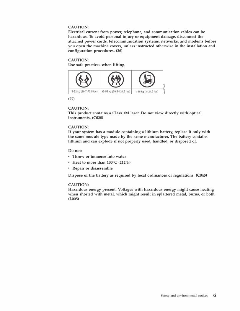
CAUTION:Use safe practices when lifting.
svc00146
18-32 kg (39.7-70.5 lbs) 32-55 kg (70.5-121.2 lbs) 55 kg ( 121.2 lbs)
(27)
CAUTION:This product contains a Class 1M laser. Do not view directly with opticalinstruments. (C028)
CAUTION:If your system has a module containing a lithium battery, replace it only withthe same module type made by the same manufacturer. The battery containslithium and can explode if not properly used, handled, or disposed of.
Do not:
v Throw or immerse into water
v Heat to more than 100°C (212°F)
v Repair or disassemble
Dispose of the battery as required by local ordinances or regulations. (C045)
CAUTION:Hazardous energy present. Voltages with hazardous energy might cause heatingwhen shorted with metal, which might result in splattered metal, burns, or both.(L005)
Safety and environmental notices xi

CAUTION:Removing components from the upper positions in the rack cabinet improvesrack stability during a relocation. Follow these general guidelines whenever yourelocate a populated rack cabinet within a room or building.
v Reduce the weight of the rack cabinet by removing equipment starting at thetop of the rack cabinet. When possible, restore the rack cabinet to theconfiguration of the rack cabinet as you received it. If this configuration is notknown, you must observe the following precautions.
– Remove all devices in the 32U position and above.
– Ensure that the heaviest devices are installed in the bottom of the rackcabinet.
– Ensure that there are no empty U-levels between devices installed in therack cabinet below the 32U level.
v If the rack cabinet you are relocating is part of a suite of rack cabinets, detachthe rack cabinet from the suite.
v If the rack cabinet you are relocating was supplied with removable outriggersthey must be reinstalled before the cabinet is relocated.
v Inspect the route that you plan to take to eliminate potential hazards.
v Verify that the route that you choose can support the weight of the loadedrack cabinet. Refer to the documentation that comes with your rack cabinet forthe weight of a loaded rack cabinet.
v Verify that all door openings are at least 760 x 230 mm (30 x 80 in.).
v Ensure that all devices, shelves, drawers, doors, and cables are secure.
v Ensure that the four leveling pads are raised to their highest position.
v Ensure that there is no stabilizer bracket installed on the rack cabinet duringmovement.
v Do not use a ramp inclined at more than 10 degrees.
v When the rack cabinet is in the new location, complete the following steps:
– Lower the four leveling pads.
– Install stabilizer brackets on the rack cabinet.
– If you removed any devices from the rack cabinet, repopulate the rackcabinet from the lowest position to the highest position.
v If a long-distance relocation is required, restore the rack cabinet to theconfiguration of the rack cabinet as you received it. Pack the rack cabinet inthe original packaging material, or equivalent. Also lower the leveling pads toraise the casters off the pallet and bolt the rack cabinet to the pallet.
(R002)
CAUTION:
v Rack is not intended to serve as an enclosure and does not provide anydegrees of protection required of enclosures.
v It is intended that equipment installed within this rack will have its ownenclosure. (R005).
CAUTION:Tighten the stabilizer brackets until they are flush against the rack. (R006)
CAUTION:Use safe practices when lifting. (R007)
xii FlashSystem 840: Installation Guide

CAUTION:Do not place any object on top of a rack-mounted device unless thatrack-mounted device is intended for use as a shelf. (R008)
CAUTION:If the rack is designed to be coupled to another rack only the same model rackshould be coupled together with another same model rack. (R009)
Danger noticesEnsure that you are familiar with the danger notices for your storage system.
Use the reference numbers in parentheses at the end of each notice, such as (C003)for example, to find the matching translated notice in IBM Systems Safety Notices.
Safety and environmental notices xiii

DANGER
When working on or around the system, observe the following precautions:
Electrical voltage and current from power, telephone, and communicationcables are hazardous. To avoid a shock hazard:
v If IBM supplied a power cord(s), connect power to this unit only with theIBM provided power cord. Do not use the IBM provided power cord forany other product.
v Do not open or service any power supply assembly.
v Do not connect or disconnect any cables or perform installation,maintenance, or reconfiguration of this product during an electrical storm.
v The product might be equipped with multiple power cords. To remove allhazardous voltages, disconnect all power cords.
v Connect all power cords to a properly wired and grounded electrical outlet.Ensure that the outlet supplies proper voltage and phase rotation accordingto the system rating plate.
v Connect any equipment that will be attached to this product to properlywired outlets.
v When possible, use one hand only to connect or disconnect signal cables.
v Never turn on any equipment when there is evidence of fire, water, orstructural damage.
v Disconnect the attached power cords, telecommunications systems,networks, and modems before you open the device covers, unlessinstructed otherwise in the installation and configuration procedures.
v Connect and disconnect cables as described in the following procedureswhen installing, moving, or opening covers on this product or attacheddevices.
To disconnect:
1. Turn off everything (unless instructed otherwise).
2. Remove the power cords from the outlets.
3. Remove the signal cables from the connectors.
4. Remove all cables from the devices.
To connect:
1. Turn off everything (unless instructed otherwise).
2. Attach all cables to the devices.
3. Attach the signal cables to the connectors.
4. Attach the power cords to the outlets.
5. Turn on the devices.
v Sharp edges, corners and joints may be present in and around the system.Use care when handling equipment to avoid cuts, scrapes and pinching.(D005)
DANGER
xiv FlashSystem 840: Installation Guide

Heavy equipment–personal injury or equipment damage might result ifmishandled. (D006)
1 2
DANGER
Multiple power cords. The product might be equipped with multiple powercords. To remove all hazardous voltages, disconnect all power cords. (L003)
DANGER
Racks with a total weight of > 227 kg (500 lb.), Use Only Professional Movers!(R003)
DANGER
Do not transport the rack via fork truck unless it is properly packaged,secured on top of the supplied pallet. (R004)
Safety and environmental notices xv

DANGER
Main Protective Earth (Ground):
This symbol is marked on the frame of the rack.
The PROTECTIVE EARTHING CONDUCTORS should be terminated at thatpoint. A recognized or certified closed loop connector (ring terminal) shouldbe used and secured to the frame with a lock washer using a bolt or stud.The connector should be properly sized to be suitable for the bold or stud,the locking washer, the rating for the conducting wire used, and theconsidered rating of the breaker. The intent is to ensure the frame iselectrically bonded to the PROTECTIVE EARTHING CONDUCTORS. Thehole that the bolt or stud goes into where the terminal conductor and the lockwasher contact should be free of any non-conductive material to allow formetal to metal contact. All PROTECTIVE EARTHING CONDUCTORSshould terminate at this main protective earthing terminal or at points
marked with . (R010)
Special caution and safety noticesThis information describes special safety notices that apply to the system. Thesenotices are in addition to the standard safety notices supplied and address specificissues relevant to the equipment provided.
Handling static-sensitive devicesEnsure that you understand how to handle devices that are sensitive to staticelectricity.
Attention: Static electricity can damage electronic devices and your system. Toavoid damage, keep static-sensitive devices in their static-protective bags until youare ready to install them.
To reduce the possibility of electrostatic discharge, observe the followingprecautions:v Limit your movement. Movement can cause static electricity to build up around
you.v Handle the device carefully, holding it by its edges or frame.v Do not touch solder joints, pins, or exposed printed circuitry.v Do not leave the device where others can handle and possibly damage the
device.v While the device is still in its antistatic bag, touch it to an unpainted metal part
of the system unit for at least two seconds. (This action removes static electricityfrom the package and from your body.)
v Remove the device from its package and install it directly into your system,without putting it down. If it is necessary to put the device down, place it ontoits static-protective bag. (If your device is an adapter, place it component-sideup.) Do not place the device onto the cover of the system or onto a metal table.
xvi FlashSystem 840: Installation Guide

v Take additional care when you handle devices during cold weather becauseheating reduces indoor humidity and increases static electricity.
Sound pressureAttention: Depending on local conditions, the sound pressure can exceed 85dB(A) during service operations. In such cases, wear appropriate hearingprotection.
Environmental noticesThe IBM Systems Environmental Notices and User Guide, Z125-5823 documentcontains all the required environmental notices for IBM Systems products inEnglish and other languages.
It includes statements on limitations, product information, product recycling anddisposal, battery information, flat panel display, refrigeration, and water-coolingsystems, external power supplies, and safety data sheets.
To view a PDF file, you need Adobe Reader. You can download it at no chargefrom the Adobe web site .
Safety and environmental notices xvii

xviii FlashSystem 840: Installation Guide

About this guide
This guide provides instructions for unpacking your shipping order and installingthe IBM FlashSystem 840.
IBM FlashSystem 840 library and related publicationsProduct manuals, other publications, and websites contain information that relatesto IBM FlashSystem™ 840.
FlashSystem 840 library
Unless otherwise noted, the publications in the library are available in Adobeportable document format (PDF) from the following website:
www.ibm.com/e-business/linkweb/publications/servlet/pbi.wss
In addition to being available on websites, the IBM Systems Safety Notices and IBMSystems Environmental Notices and User Guide are shipped on CD with the product.
Table 1 lists websites where you can find help, services, and more information.
Table 1. IBM websites for help, services, and information
Website Address
Directory of worldwide contacts http://www.ibm.com/planetwide
Support for IBM System Storage® and IBM TotalStorageproducts
www.ibm.com/support
Each of the PDF publications in the FlashSystem 840 library is also available in theinformation center by clicking the number in the “Order number” column:
Table 2. IBM FlashSystem 840 library
Title Description Order number
IBM FlashSystem 840Installation Guide
This guide providesinstructions forunpacking yourshipping order andinstalling your system.The first of threechapters describesplanning for the systeminstallation. The secondchapter describesinstalling the hardwareand attaching datacables and power cords.The last chapterdescribes initialconfiguration of yoursystem.
GI13-2871
© Copyright IBM Corp. 2014, xix

Table 2. IBM FlashSystem 840 library (continued)
Title Description Order number
IBM FlashSystem 840Troubleshooting, Recovery, andMaintenance Guide
This guide describeshow to service,maintain, andtroubleshoot yoursystem.
SC27-6297-00
IBM FlashSystem 840Installation Poster
The installation posterprovides an illustratedsequence of steps forinstalling the enclosurein a rack and beginningthe setup process.
SC27-6296-00
IBM Systems Safety Notices This guide containstranslated caution anddanger statements. Eachcaution and dangerstatement in the IBMFlashSystem 840documentation has anumber that you can useto locate thecorresponding statementin your language in theIBM Systems SafetyNotices document.
G229-9054
Warranty Information Flyer This multilingualdocument providesinformation about theIBM warranty for IBMFlashSystem 840.
00DJ102
Publications for other IBM FlashSystem products
Table 3 lists publications that contain information related to other IBM FlashSystemproducts.
Table 3. Publications for other IBM FlashSystem products
Title Description Order Number
Installing the IBMFlashSystem 710
This guide describes initial setupand configuration of the IBMFlashSystem 710 system.
GI11-9893-00
IBM FlashSystem 710 User'sGuide
This guide describes how to setup, configure, and manage theIBM FlashSystem 710 system.
Download
Installing the IBMFlashSystem 720
This guide describes initial setupand configuration of the IBMFlashSystem 720 system.
GI11-9895-00
IBM FlashSystem 720 User'sGuide
This guide describes how to setup, configure, and manage theIBM FlashSystem 720 system.
Download
Installing the IBMFlashSystem 810
This guide describes initial setupand configuration of the IBMFlashSystem 810 system.
GI11-9894-00
xx FlashSystem 840: Installation Guide
Table 3. Publications for other IBM FlashSystem products (continued)
Title Description Order Number
IBM FlashSystem 810 User'sGuide
This guide describes how to setup, configure, and manage theIBM FlashSystem 810 system.
Download
Installing the IBMFlashSystem 820
This guide describes initial setupand configuration of the IBMFlashSystem 820 system.
GI11-9896-00
IBM FlashSystem 820 User'sGuide
This guide describes how to setup, configure, and manage theIBM FlashSystem 820 system.
Download
IBM FlashSystem SCSIInterface Guide
This guide describes the SCSIcommands that are supported bythe IBM FlashSystem 710, 720,810, and 820 systems.
Download
IBM FlashSystem SNMPGuide
This guide describes how to setup, configure, and use SimpleNetwork Management Protocol(SNMP) on the IBM FlashSystem710, 720, 810, and 820 systems.
Download
IBM FlashSystem WebInterface Guide
This guide describes how toaccess and use the webmanagement interface for theIBM FlashSystem 710, 720, 810,and 820 systems.
Download
IBM FlashSystem IntegrationGuide
This guide describes how toimprove the performance of IBMFlashSystem 710, 720, 810, and820 systems by applying specificconnectivity, storageconfigurations, and alignmentstrategies.
Download
Troubleshooting and CRUService for IBM FlashSystem710, IBM FlashSystem 810,IBM FlashSystem 720, IBMFlashSystem 820
This guide describestroubleshooting resources andservice procedures forcustomer-replaceable parts.
Download
IBM documentation and related websites
Table 4 lists websites that provide publications and other information about thesystem or related products or technologies.
Table 4. IBM documentation and related websites
Website Address
IBM Publications Center www.ibm.com/e-business/linkweb/publications/servlet/pbi.wss
IBM Redbooks® publications www.redbooks.ibm.com/
Related accessibility information
To view a PDF file, you need Adobe Reader, which can be downloaded from theAdobe website:
About this guide xxi

www.adobe.com/support/downloads/main.html
Related websitesThe following websites provide information about FlashSystem 840 or relatedproducts or technologies:
Type of information Website
Technical support for IBM storageproducts
www.ibm.com/storage/support/
IBM Electronic Support registration www.ibm.com/support/electronicsupport
How to get information, help, and technical assistanceIf you need help, service, technical assistance, or just want more information aboutIBM products, you will find a wide variety of sources available from IBM to assistyou.
Information
IBM maintains pages on the web where you can get information about IBMproducts and fee services, product implementation and usage assistance, break andfix service support, and the latest technical information. For more information,refer to Table 5.
Table 5. IBM websites for help, services, and information
Website Address
Directory of worldwide contacts http://www.ibm.com/planetwide
Support for FlashSystem 840 www.ibm.com/support/
Support for IBM System Storageand IBM TotalStorage products
www.ibm.com/storage/support/
Note: Available services, telephone numbers, and web links are subject to changewithout notice.
Help and service
Before calling for support, be sure to have your IBM Customer Number available.If you are in the US or Canada, you can call 1 (800) IBM SERV for help andservice. From other parts of the world, see http://www.ibm.com/planetwide forthe number that you can call.
When calling from the US or Canada, choose the storage option. The agent decideswhere to route your call, to either storage software or storage hardware, dependingon the nature of your problem.
If you call from somewhere other than the US or Canada, you must choose thehardware option when calling for assistance. When calling IBM for serviceregarding the product, follow these guidelines for the hardware :
Hardware optionProvide the serial number and appropriate 4-digit machine type. ForFlashSystem 840, the machine type is 9840.
xxii FlashSystem 840: Installation Guide

In the US and Canada, hardware service and support can be extended to 24x7 onthe same day. The base warranty is 9x5 on the next business day.
Getting help online
You can find information about products, solutions, partners, and support on theIBM website.
To find up-to-date information about products, services, and partners, visit the IBMwebsite at www.ibm.com/support/.
Before you call
Make sure that you have taken steps to try to solve the problem yourself beforeyou call.
Some suggestions for resolving the problem before calling IBM Support include:v Check all cables to make sure that they are connected.v Check all power switches to make sure that the system and optional devices are
turned on.v Use the troubleshooting information in your system documentation. The
troubleshooting section of the information center contains procedures to helpyou diagnose problems.
v Go to the IBM Support website at www.ibm.com/support/ to check fortechnical information, hints, tips, and new device drivers or to submit a requestfor information.
Using the documentation
Information about your IBM storage system is available in the documentation thatcomes with the product.
That documentation includes printed documents, online documents, readme files,and help files in addition to the information center. See the troubleshootinginformation for diagnostic instructions. The troubleshooting procedure mightrequire you to download updated device drivers or software. IBM maintains pageson the web where you can get the latest technical information and downloaddevice drivers and updates. To access these pages, go to www.ibm.com/support/and follow the instructions. Also, some documents are available through the IBMPublications Center.
Sign up for the Support Line Offering
If you have questions about how to use and configure the machine, sign up for theIBM Support Line offering to get a professional answer.
The maintenance supplied with the system provides support when there is aproblem with a hardware component or a fault in the system machine code. Attimes, you might need expert advice about using a function provided by thesystem or about how to configure the system. Purchasing the IBM Support Lineoffering gives you access to this professional advice while deploying your system,and in the future.
Contact your local IBM sales representative or the IBM Support Center foravailability and purchase information.
About this guide xxiii

xxiv FlashSystem 840: Installation Guide

Chapter 1. Planning
Use this information when planning to include your IBM FlashSystem 840 in yourstorage area network.
PlanningUse this information when planning to include your IBM FlashSystem 840 in yourstorage area network.
Planning for hardwarePlan to provide the network infrastructure and the storage network infrastructurethat your system requires.
Planning cable connectionsPlan to set up cable connections to the enclosure.
You can use the following tables to record the details of the cable connections foryour system.
Management port connections
Each canister includes an Ethernet port for accessing the management GUI.
The following table shows the management port connections:
Table 6. Enclosure management port Ethernet connections
Canister Management Port
Canister 1EthernetManagement Port
switch:
port:
speed:
Canister 2EthernetManagement Port
switch:
port:
speed:
Important: Three IP addresses are required for managing the storage enclosure: acluster IP address and two service IP addresses. Each of the three IP addressesmust be a unique value.
Use the following table to record the cluster and service IP address settings for thestorage enclosure.
Table 7. IP addresses for the storage enclosure
Cluster name:
Cluster IP address:
IP:
Subnet mask:
Gateway:
© Copyright IBM Corp. 2014, 1

Table 7. IP addresses for the storage enclosure (continued)
Service IP address 1:
IP:
Subnet mask:
Gateway:
Service IP address 2:
IP:
Subnet mask:
Gateway:
Interface card connections
Important: Each host should be connected to both canisters, to add redundancyand improve performance.
Each canister supports two optional Fibre Channel interface cards. 8 Gb FC cardssupport four ports. 16 Gb cards support two ports.
Note: SFP transceivers should be obtained and deployed in pairs to supportmultipathing.
The following table shows the Fibre Channel port connections:
Table 8. Fibre Channel port connections
Fibre Channel port 1 Fibre Channel port 2Fibre Channel port 3
(8 Gb FC only)Fibre Channel port 4
(8 Gb FC Only)
Canister 1FibreChannelcard 1(left)
switchor host:
port:
speed:
Canister 1FibreChannelcard 2(right)
switchor host:
port:
speed:
Canister 2FibreChannelcard 1(left)
switchor host:
port:
speed:
Canister 2FibreChannelcard 2(right)
switchor host:
port:
speed:
Each canister supports two optional Fibre Channel over Ethernet (FCoE) interfacecards. There are four ports on each card.
2 FlashSystem 840: Installation Guide

Note: SFP transceivers should be obtained and deployed in pairs to supportmultipathing.
The following table shows the FCoE port connections:
Table 9. FCoE port connections
FCoE Port 1 FCoE Port 2 FCoE Port 3 FCoE port 4
Canister 1FCoE card1 (left)
switchor host:
port:
speed:
Canister 1FCoE card2 (right)
switchor host:
port:
speed:
Canister 2FCoE card1 (left)
switchor host:
port:
speed:
Canister 2FCoE card2 (right)
switchor host:
port:
speed:
Each canister supports two optional InfiniBand interface cards. There are two portson each card.
The following table shows the InfiniBand port connections:
Table 10. InfiniBand port connections
InfiniBand port 1 InfiniBand port 2
Canister 1 InfiniBandcard 1 (left)
switch orhost:
port:
Canister 1 InfiniBandcard 2 (right)
switch orhost:
port:
Canister 2 InfiniBandcard 1 (left)
switch orhost:
port:
Canister 2 InfiniBandcard 2 (right)
switch orhost:
port:
Chapter 1. Planning 3

The following table shows switch information:
Table 11. Switch Information
IPv4 address IPv6 address MAC address Physical location
Switch 1
Switch 2
Switch 3
Switch 4
Planning for powerPlan to attach each of the two power supplies in the enclosure to separate mainpower supply lines.
Plan to connect the power cords on the right side of the rack (when viewed fromthe rear) to power sources that provides power in the 100-127V / 200-240V acrange at 10.0/5.0A 50/60 Hz. Each power supply requires 900 watts. Using twopower sources provides power redundancy.
Note: We recommend that the two power supplies are placed on different circuits.
The power cables are specific to the power requirements of your country or region.
Attention: The power cord is the main power disconnect. Ensure that the socketoutlets are located near the equipment and are easily accessible.
Planning for configurationPlan for the management and service address data before the system is installed.
A management address must be allocated for the system. The management addressprovides access to system configuration and administration functions such as themanagement GUI.
Important: The management and service addresses for the enclosure must beallocated within the same network.
The management IP address is required when the system is initialized. The systeminitialization tool that is provided on a USB flash drive provides a convenient“wizard” for initializing the system and configuring service IP addresses.
Use Table 12 to record the management IP address that is allocated for use by thesystem.
Table 12. Management IP address configuration
Configuration item Value
Management IP address
Subnet mask
Gateway address
Two service addresses must be allocated to the enclosure. The enclosure canistersretain the service IP addresses, allowing convenient access to node configurationand service functions, such as the service assistant GUI and CLI for that node; IPv4and IPv6 protocols can be used.
4 FlashSystem 840: Installation Guide

Use Table 13 to plan the service addresses required to perform service actions.
Table 13. Service IP address configuration
Configuration item Value
Service Address 1
Management IP address
Subnet mask
Gateway address
Service Address 2
Management IP address
Subnet mask
Gateway address
Use Table 14 to configure the system for event notification.
Table 14. Event notification settings
Configuration item Value
Email server addresses
SNMP server addresses
SNMP community strings
Syslog servers
TCP/IP requirementsTo plan your installation, consider the TCP/IP address requirements of the systemand the requirements to access other services. You must also plan for the Ethernetaddress allocation and for the configuration of the Ethernet router, gateway, andfirewall.
The following table shows the services and TCP/IP ports:
Table 15. TCP/IP ports and services listing
Service Traffic direction Protocol Port Service type
Email (SMTP) notification for Call Home andinventory reporting Outbound TCP 25 optional
SNMP event notification Outbound UDP 162 optional
Syslog event notification Outbound UDP 514 optional
IPv4 DHCP (Node service address) Outbound UDP 68 optional
IPv6 DHCP (Node service address) Outbound UDP 547 optional
Network time server (NTP) Outbound UDP 123 optional
SSH for command line interface (CLI) access Inbound TCP 22 mandatory
HTTPS for GUI access Inbound TCP 443 mandatory
Remote user authentication service - HTTP Outbound TCP 16310 optional
Remote user authentication service - HTTPS Outbound TCP 16311 optional
Remote user authentication service - LightweightDirectory Access Protocol (LDAP) Outbound TCP 389 optional
Wake On LAN Inbound N/A N/A mandatory
Chapter 1. Planning 5

Both IPv4 and IPv6 addresses are supported.
For configuration and management, you must allocate an IP address to theEthernet management port on each canister, which is referred to as themanagement IP address. If both IPv4 and IPv6 are operating concurrently, anaddress is required for each protocol.
You can configure the enclosure for event notification by SNMP, syslog, or email.To configure notification, you must ensure that the SNMP agent, syslog IPaddresses, or SMTP email server IP addresses can be accessed from allmanagement addresses.
The system does not use name servers to locate other devices. You must supply thenumeric IP address of the device. To locate a device, the device must have a fixedIP address.
Checking your web browser settings for the management GUITo access the management GUI, you must ensure that your web browser issupported and has the appropriate settings enabled.
Before you begin
The management GUI supports the following web browsers:v Mozilla Firefox 27v Mozilla Firefox Extended Support Release (ESR) 24v Microsoft Internet Explorer (IE) 9 and 10v Google Chrome 33
IBM supports higher versions of the browsers as long as the vendors do notremove or disable functionality that the product relies upon. For browser levelshigher than the versions that are certified with the product, customer supportaccepts usage-related and defect-related service requests. As with operating systemand virtualization environments, if IBM support cannot re-create the issue in ourlab, we might ask the client to re-create the problem on a certified browser versionto determine whether a product defect exists. Defects are not accepted for cosmeticdifferences between browsers or browser versions that do not affect the functionalbehavior of the product. If a problem is identified in the product, defects areaccepted. If a problem is identified with the browser, IBM might investigatepotential solutions or work-arounds that the client can implement until apermanent solution becomes available.
Procedure
To configure your web browser, follow these steps:1. Enable JavaScript for your web browser.
For Mozilla Firefox:a. On the menu bar in the Firefox browser window, click Tools > Options.b. On the Options window, select Content.c. Select Enable JavaScript.d. Click OK.e. Refresh your browser.
6 FlashSystem 840: Installation Guide
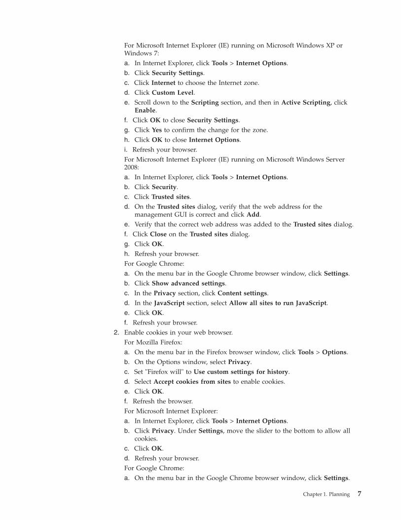
For Microsoft Internet Explorer (IE) running on Microsoft Windows XP orWindows 7:a. In Internet Explorer, click Tools > Internet Options.b. Click Security Settings.c. Click Internet to choose the Internet zone.d. Click Custom Level.e. Scroll down to the Scripting section, and then in Active Scripting, click
Enable.f. Click OK to close Security Settings.g. Click Yes to confirm the change for the zone.h. Click OK to close Internet Options.i. Refresh your browser.For Microsoft Internet Explorer (IE) running on Microsoft Windows Server2008:a. In Internet Explorer, click Tools > Internet Options.b. Click Security.c. Click Trusted sites.d. On the Trusted sites dialog, verify that the web address for the
management GUI is correct and click Add.e. Verify that the correct web address was added to the Trusted sites dialog.f. Click Close on the Trusted sites dialog.g. Click OK.h. Refresh your browser.For Google Chrome:a. On the menu bar in the Google Chrome browser window, click Settings.b. Click Show advanced settings.c. In the Privacy section, click Content settings.d. In the JavaScript section, select Allow all sites to run JavaScript.e. Click OK.f. Refresh your browser.
2. Enable cookies in your web browser.For Mozilla Firefox:a. On the menu bar in the Firefox browser window, click Tools > Options.b. On the Options window, select Privacy.c. Set "Firefox will" to Use custom settings for history.d. Select Accept cookies from sites to enable cookies.e. Click OK.f. Refresh the browser.For Microsoft Internet Explorer:a. In Internet Explorer, click Tools > Internet Options.b. Click Privacy. Under Settings, move the slider to the bottom to allow all
cookies.c. Click OK.d. Refresh your browser.For Google Chrome:a. On the menu bar in the Google Chrome browser window, click Settings.
Chapter 1. Planning 7

b. Click Show advanced settings.c. In the Privacy section, click Content settings.d. In the Cookies section, select Allow local data to be set.e. Click OK.f. Refresh your browser.
3. Enable scripts to disable or replace context menus. (Mozilla Firefox only).For Mozilla Firefox:a. On the menu bar in the Firefox browser window, click Tools > Options.b. On the Options window, select Content.c. Click Advanced by the Enable JavaScript setting.d. Select Disable or replace context menus.e. Click OK to close the Advanced window.f. Click OK to close the Options window.g. Refresh your browser.
8 FlashSystem 840: Installation Guide

Chapter 2. Installing the hardware
Learn how to set up the rails, install the system hardware, connect the cables andpower on the system.
Before you begin the installationBefore you begin to install your FlashSystem 840, unpack and verify your order.
Get started with the system installation and follow the installation instructions.Verify your order, become familiar with the hardware components, and ensure thatthe environmental requirements are met. Next, install the hardware and attach thedata cables and power cords. When the installation finishes, access themanagement GUI to initialize your system.
Tools needed
You need a flat-blade screwdriver and two Ethernet cables for the systeminstallation.
Be familiar with the following informationv Use safe practices when lifting. The fully populated enclosure weighs about 26
kg (57 lbs). At least two people are required to lift and install the enclosure intothe rack or to remove an enclosure from the rack.CAUTION:Use safe practices when lifting.
svc00146
18-32 kg (39.7-70.5 lbs) 32-55 kg (70.5-121.2 lbs) 55 kg ( 121.2 lbs)
(27)
Also, keep in mind that a rack full of equipment is heavy.
DANGER: Heavy equipment–personal injury or equipment damage mightresult if mishandled. (D006)
CAUTION:
The weight of this part or unit is between 32 and 55 kg (70.5 and 121.2 lb). Ittakes three persons to safely lift this part or unit. (C010)
svc0
0384
32-55 kg (70.5-121.2 lbs)>32 kg (70.5 lb)or or
© Copyright IBM Corp. 2014, 9

v Observe the following precautions even though the steps to power on thesystem differ slightly from the directions you use for this product.
10 FlashSystem 840: Installation Guide

DANGER
When working on or around the system, observe the following precautions:
Electrical voltage and current from power, telephone, and communicationcables are hazardous. To avoid a shock hazard:
– If IBM supplied a power cord(s), connect power to this unit only withthe IBM provided power cord. Do not use the IBM provided power cordfor any other product.
– Do not open or service any power supply assembly.
– Do not connect or disconnect any cables or perform installation,maintenance, or reconfiguration of this product during an electricalstorm.
– The product might be equipped with multiple power cords. To removeall hazardous voltages, disconnect all power cords.
– Connect all power cords to a properly wired and grounded electricaloutlet. Ensure that the outlet supplies proper voltage and phase rotationaccording to the system rating plate.
– Connect any equipment that will be attached to this product to properlywired outlets.
– When possible, use one hand only to connect or disconnect signal cables.
– Never turn on any equipment when there is evidence of fire, water, orstructural damage.
– Disconnect the attached power cords, telecommunications systems,networks, and modems before you open the device covers, unlessinstructed otherwise in the installation and configuration procedures.
– Connect and disconnect cables as described in the following procedureswhen installing, moving, or opening covers on this product or attacheddevices.
To disconnect:
1. Turn off everything (unless instructed otherwise).
2. Remove the power cords from the outlets.
3. Remove the signal cables from the connectors.
4. Remove all cables from the devices.
To connect:
1. Turn off everything (unless instructed otherwise).
2. Attach all cables to the devices.
3. Attach the signal cables to the connectors.
4. Attach the power cords to the outlets.
5. Turn on the devices.
– Sharp edges, corners and joints may be present in and around thesystem. Use care when handling equipment to avoid cuts, scrapes andpinching. (D005)
Reviewing your packaging slipYour system is supplied with a packing list. Ensure that you received all of thecomponents listed.
Chapter 2. Installing the hardware 11

In each box, locate the packing slip. Verify that the items listed in the packing slipmatch what is in the box, and that any optional items that you ordered areincluded. Depending on your order, your shipment might contain extra items.__ v Enclosure__ v Two power cables__ v Rail kit and screws__ v Two battery modules__ v Installation poster__ v Publications package. This package includes documentation and a USB flash
drive used to initialize the system. Additional USB drives are included if theoptional encryption feature is purchased.
__ v Network cables
Your system might include other items, including SFP transceivers.
Installing the hardwareLearn how to set up the rails, install the system hardware, connect the cables andpower on the system.
Installing the support rails for the storage enclosureBefore you install the storage enclosure, you must first install the support rails.
Procedure
To install the support rails, complete the following steps.1. Locate the rack mounting rails and screws (Figure 1). The rail assembly
consists of two rails that must be installed in the rack cabinet.
2. Your rack mounting rails may include a u-shaped bolt, which is shown inFigure 1, that must be removed before installing the rails. If this u-bolt ispresent, remove the u-bolt by removing the two nuts that secure the bolt tothe rail.
v3500168
Figure 1. Rack mounting rails and screws
12 FlashSystem 840: Installation Guide
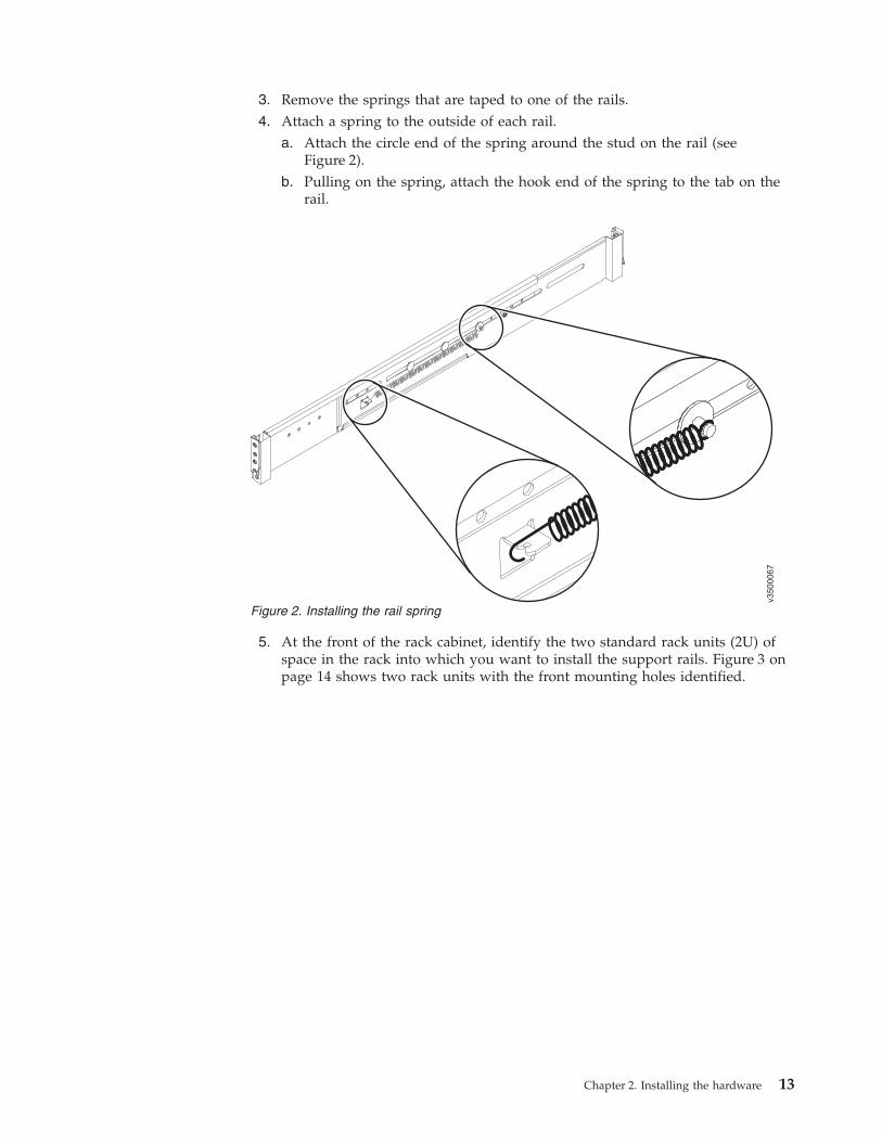
3. Remove the springs that are taped to one of the rails.4. Attach a spring to the outside of each rail.
a. Attach the circle end of the spring around the stud on the rail (seeFigure 2).
b. Pulling on the spring, attach the hook end of the spring to the tab on therail.
5. At the front of the rack cabinet, identify the two standard rack units (2U) ofspace in the rack into which you want to install the support rails. Figure 3 onpage 14 shows two rack units with the front mounting holes identified.
v3500067
Figure 2. Installing the rail spring
Chapter 2. Installing the hardware 13

�1� Upper rail mounting bracket pin�2� Rack mounting screw hole�3� Lower rail mounting bracket pin
Note: Each rail comes with two medium bracket pins in the front bracket andtwo medium bracket pins in the rear bracket. The medium bracket pins are forinstallation in a 19-inch IBM rack cabinet. If you are installing the enclosure ina non-IBM rack cabinet, you might need to replace the set of medium bracketpins on the front and rear of the rail with either the small or large bracketpins that are included in the rail kit.
6. At each end of the rail, grasp the tab �1� and pull firmly to open the hingebracket (see Figure 4 on page 15).
Figure 3. Hole locations in the front of the rack
14 FlashSystem 840: Installation Guide

7. Align the holes in the rail bracket with the holes on the front and rear rackcabinet flanges. Ensure that the rails are aligned on the inside of the rackcabinet.
8. On the rear of the rail, press the two bracket pins into the holes in the rackflanges and close the rear hinge bracket to secure the rail to the rack cabinetflange (see Figure 5 on page 16).
v3500116
1
Figure 4. Opening the hinge brackets
Chapter 2. Installing the hardware 15

9. On the front of the rail, press the two bracket pins into the holes in the rackflanges and close the front hinge bracket to secure the rail to the rack cabinetflange (see Figure 5).
10. Secure the rear of the rail to the rear rack flange by installing an M5 screwbetween the upper and lower mounting pins (see Figure 5).
11. Repeat steps 7 on page 15 through 10 to secure the opposite rail to the rackcabinet.
Installing the enclosure in a rackFollowing your location plan, install the enclosure in the rack.
Before you begin
CAUTION:To avoid any hazard from the rack tipping forward when devices are installed,observe all safety precautions for the rack into which you are installing thedevice.
Figure 5. Closing hinge brackets and installing rear screw
16 FlashSystem 840: Installation Guide

About this task
CAUTION:
The weight of this part or unit is between 32 and 55 kg (70.5 and 121.2 lb). Ittakes three persons to safely lift this part or unit. (C010)
DANGER
Observe the following precautions when working on or around your IT racksystem:
v Heavy equipment–personal injury or equipment damage might result ifmishandled.
v Always lower the leveling pads on the rack cabinet.
v Always install stabilizer brackets on the rack cabinet.
v To avoid hazardous conditions due to uneven mechanical loading, alwaysinstall the heaviest devices in the bottom of the rack cabinet. Always installservers and optional devices starting from the bottom of the rack cabinet.
v Rack-mounted devices are not to be used as shelves or work spaces. Do notplace objects on top of rack-mounted devices.
v Each rack cabinet might have more than one power cord. Be sure todisconnect all power cords in the rack cabinet when directed to disconnectpower during servicing.
v Connect all devices installed in a rack cabinet to power devices installed inthe same rack cabinet. Do not plug a power cord from a device installed inone rack cabinet into a power device installed in a different rack cabinet.
v An electrical outlet that is not correctly wired could place hazardousvoltage on the metal parts of the system or the devices that attach to thesystem. It is the responsibility of the customer to ensure that the outlet iscorrectly wired and grounded to prevent an electrical shock.
(R001 part 1 of 2)
svc00384
32-55 kg (70.5-121.2 lbs)>32 kg (70.5 lb)or or
Chapter 2. Installing the hardware 17

CAUTION:
v Do not install a unit in a rack where the internal rack ambient temperatureswill exceed the manufacturer's recommended ambient temperature for all yourrack-mounted devices.
v Do not install a unit in a rack where the air flow is compromised. Ensure thatair flow is not blocked or reduced on any side, front, or back of a unit usedfor air flow through the unit.
v Consideration should be given to the connection of the equipment to thesupply circuit so that overloading of the circuits does not compromise thesupply wiring or overcurrent protection. To provide the correct powerconnection to a rack, refer to the rating labels located on the equipment in therack to determine the total power requirement of the supply circuit.
v (For sliding drawers) Do not pull out or install any drawer or feature if therack stabilizer brackets are not attached to the rack. Do not pull out more thanone drawer at a time. The rack might become unstable if you pull out morethan one drawer at a time.
v (For fixed drawers) This drawer is a fixed drawer and must not be moved forservicing unless specified by the manufacturer. Attempting to move thedrawer partially or completely out of the rack might cause the rack to becomeunstable or cause the drawer to fall out of the rack.
(R001 part 2 of 2)
18 FlashSystem 840: Installation Guide

CAUTION:Removing components from the upper positions in the rack cabinet improvesrack stability during a relocation. Follow these general guidelines whenever yourelocate a populated rack cabinet within a room or building.
v Reduce the weight of the rack cabinet by removing equipment starting at thetop of the rack cabinet. When possible, restore the rack cabinet to theconfiguration of the rack cabinet as you received it. If this configuration is notknown, you must observe the following precautions.
– Remove all devices in the 32U position and above.
– Ensure that the heaviest devices are installed in the bottom of the rackcabinet.
– Ensure that there are no empty U-levels between devices installed in therack cabinet below the 32U level.
v If the rack cabinet you are relocating is part of a suite of rack cabinets, detachthe rack cabinet from the suite.
v If the rack cabinet you are relocating was supplied with removable outriggersthey must be reinstalled before the cabinet is relocated.
v Inspect the route that you plan to take to eliminate potential hazards.
v Verify that the route that you choose can support the weight of the loadedrack cabinet. Refer to the documentation that comes with your rack cabinet forthe weight of a loaded rack cabinet.
v Verify that all door openings are at least 760 x 230 mm (30 x 80 in.).
v Ensure that all devices, shelves, drawers, doors, and cables are secure.
v Ensure that the four leveling pads are raised to their highest position.
v Ensure that there is no stabilizer bracket installed on the rack cabinet duringmovement.
v Do not use a ramp inclined at more than 10 degrees.
v When the rack cabinet is in the new location, complete the following steps:
– Lower the four leveling pads.
– Install stabilizer brackets on the rack cabinet.
– If you removed any devices from the rack cabinet, repopulate the rackcabinet from the lowest position to the highest position.
v If a long-distance relocation is required, restore the rack cabinet to theconfiguration of the rack cabinet as you received it. Pack the rack cabinet inthe original packaging material, or equivalent. Also lower the leveling pads toraise the casters off the pallet and bolt the rack cabinet to the pallet.
(R002)
v Load the rack from the bottom up to ensure rack stability. Empty the rack fromthe top down.
Important: The enclosure and battery modules are shipped separately. You mustinstall the battery modules after you install the enclosure in the rack.
Procedure
To install an enclosure, complete the following steps.1. Align the enclosure with the front of the rack cabinet.2. Carefully slide the enclosure into the rack along the rails until the enclosure is
fully inserted (see Figure 6 on page 20).
Chapter 2. Installing the hardware 19

Note: The rails are not designed to hold an enclosure that is partially inserted.The enclosure must always be in a fully inserted position.
3. Secure the enclosure to the rack with a screw in the rack mounting screw holeon each side of the enclosure.
4. Install the two battery modules.
Connecting the management port Ethernet cablesLearn how to connect the Ethernet cables to the management ports on theenclosure.
Figure 6. Inserting the enclosure
20 FlashSystem 840: Installation Guide

About this task
DANGER
When working on or around the system, observe the following precautions:
Electrical voltage and current from power, telephone, and communicationcables are hazardous. To avoid a shock hazard:
v If IBM supplied a power cord(s), connect power to this unit only with theIBM provided power cord. Do not use the IBM provided power cord forany other product.
v Do not open or service any power supply assembly.
v Do not connect or disconnect any cables or perform installation,maintenance, or reconfiguration of this product during an electrical storm.
v The product might be equipped with multiple power cords. To remove allhazardous voltages, disconnect all power cords.
v Connect all power cords to a properly wired and grounded electrical outlet.Ensure that the outlet supplies proper voltage and phase rotation accordingto the system rating plate.
v Connect any equipment that will be attached to this product to properlywired outlets.
v When possible, use one hand only to connect or disconnect signal cables.
v Never turn on any equipment when there is evidence of fire, water, orstructural damage.
v Disconnect the attached power cords, telecommunications systems,networks, and modems before you open the device covers, unlessinstructed otherwise in the installation and configuration procedures.
v Connect and disconnect cables as described in the following procedureswhen installing, moving, or opening covers on this product or attacheddevices.
To disconnect:
1. Turn off everything (unless instructed otherwise).
2. Remove the power cords from the outlets.
3. Remove the signal cables from the connectors.
4. Remove all cables from the devices.
To connect:
1. Turn off everything (unless instructed otherwise).
2. Attach all cables to the devices.
3. Attach the signal cables to the connectors.
4. Attach the power cords to the outlets.
5. Turn on the devices.
v Sharp edges, corners and joints may be present in and around the system.Use care when handling equipment to avoid cuts, scrapes and pinching.(D005)
To provide redundant system management connectivity, connect an Ethernet cableto the management port on each canister in the enclosure.
Chapter 2. Installing the hardware 21

The following illustration shows the management port connector location on eachcanister.
�1� Management port connectors
Procedure1. Connect an Ethernet cable to the management port on each canister.2. Connect the other end of the cable to a management workstation, or to the
Ethernet network.
Connecting Fibre Channel, FCoE, or InfiniBand cablesLearn how to connect the Fibre Channel (FC), Fibre Channel over Ethernet (FCoE),or InfiniBand cables to your system.
Figure 7. Management port connectors
22 FlashSystem 840: Installation Guide

About this task
DANGER
When working on or around the system, observe the following precautions:
Electrical voltage and current from power, telephone, and communicationcables are hazardous. To avoid a shock hazard:
v If IBM supplied a power cord(s), connect power to this unit only with theIBM provided power cord. Do not use the IBM provided power cord forany other product.
v Do not open or service any power supply assembly.
v Do not connect or disconnect any cables or perform installation,maintenance, or reconfiguration of this product during an electrical storm.
v The product might be equipped with multiple power cords. To remove allhazardous voltages, disconnect all power cords.
v Connect all power cords to a properly wired and grounded electrical outlet.Ensure that the outlet supplies proper voltage and phase rotation accordingto the system rating plate.
v Connect any equipment that will be attached to this product to properlywired outlets.
v When possible, use one hand only to connect or disconnect signal cables.
v Never turn on any equipment when there is evidence of fire, water, orstructural damage.
v Disconnect the attached power cords, telecommunications systems,networks, and modems before you open the device covers, unlessinstructed otherwise in the installation and configuration procedures.
v Connect and disconnect cables as described in the following procedureswhen installing, moving, or opening covers on this product or attacheddevices.
To disconnect:
1. Turn off everything (unless instructed otherwise).
2. Remove the power cords from the outlets.
3. Remove the signal cables from the connectors.
4. Remove all cables from the devices.
To connect:
1. Turn off everything (unless instructed otherwise).
2. Attach all cables to the devices.
3. Attach the signal cables to the connectors.
4. Attach the power cords to the outlets.
5. Turn on the devices.
v Sharp edges, corners and joints may be present in and around the system.Use care when handling equipment to avoid cuts, scrapes and pinching.(D005)
The enclosure contains four interface cards (two per canister). The interface cardsare on the enclosure rear panel, as shown in Figure 8 on page 24.
Chapter 2. Installing the hardware 23
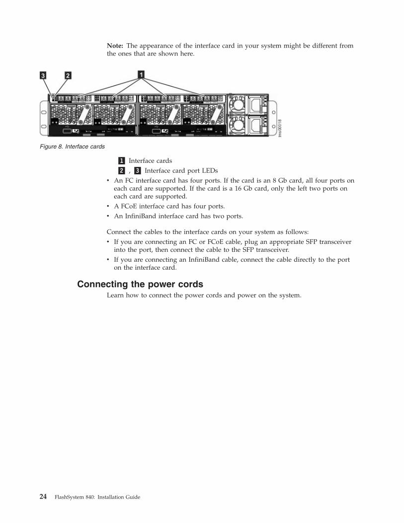
Note: The appearance of the interface card in your system might be different fromthe ones that are shown here.
�1� Interface cards�2� , �3� Interface card port LEDs
v An FC interface card has four ports. If the card is an 8 Gb card, all four ports oneach card are supported. If the card is a 16 Gb card, only the left two ports oneach card are supported.
v A FCoE interface card has four ports.v An InfiniBand interface card has two ports.
Connect the cables to the interface cards on your system as follows:v If you are connecting an FC or FCoE cable, plug an appropriate SFP transceiver
into the port, then connect the cable to the SFP transceiver.v If you are connecting an InfiniBand cable, connect the cable directly to the port
on the interface card.
Connecting the power cordsLearn how to connect the power cords and power on the system.
Figure 8. Interface cards
24 FlashSystem 840: Installation Guide

About this task
DANGER
When working on or around the system, observe the following precautions:
Electrical voltage and current from power, telephone, and communicationcables are hazardous. To avoid a shock hazard:
v If IBM supplied a power cord(s), connect power to this unit only with theIBM provided power cord. Do not use the IBM provided power cord forany other product.
v Do not open or service any power supply assembly.
v Do not connect or disconnect any cables or perform installation,maintenance, or reconfiguration of this product during an electrical storm.
v The product might be equipped with multiple power cords. To remove allhazardous voltages, disconnect all power cords.
v Connect all power cords to a properly wired and grounded electrical outlet.Ensure that the outlet supplies proper voltage and phase rotation accordingto the system rating plate.
v Connect any equipment that will be attached to this product to properlywired outlets.
v When possible, use one hand only to connect or disconnect signal cables.
v Never turn on any equipment when there is evidence of fire, water, orstructural damage.
v Disconnect the attached power cords, telecommunications systems,networks, and modems before you open the device covers, unlessinstructed otherwise in the installation and configuration procedures.
v Connect and disconnect cables as described in the following procedureswhen installing, moving, or opening covers on this product or attacheddevices.
To disconnect:
1. Turn off everything (unless instructed otherwise).
2. Remove the power cords from the outlets.
3. Remove the signal cables from the connectors.
4. Remove all cables from the devices.
To connect:
1. Turn off everything (unless instructed otherwise).
2. Attach all cables to the devices.
3. Attach the signal cables to the connectors.
4. Attach the power cords to the outlets.
5. Turn on the devices.
v Sharp edges, corners and joints may be present in and around the system.Use care when handling equipment to avoid cuts, scrapes and pinching.(D005)
1 2
Chapter 2. Installing the hardware 25

DANGER
Multiple power cords. The product might be equipped with multiple powercords. To remove all hazardous voltages, disconnect all power cords. (L003)
To power on the system, complete the following steps:
Note: Though the system operates when only one power supply unit is connected,this configuration is not recommended. Using the power cords that are provided,connect each power supply unit to a power source. If possible, connect each of thepower cords to separate circuits.
Figure 9 shows the power connector location on the power supply units.
�1� , �2� Power connectors
Procedure1. Connect the two power cords to the two power connectors on the system.2. Plug the two power cords into properly grounded electrical outlets, such as on
a power distribution unit (PDU). . Wait for the power LED to come on, blinkand then come on solid. The process can take up to 10 minutes.Figure 10 shows the canister LEDs on the enclosure rear panel that display thesystem status after it starts. Each canister has a set of these LEDs.
�1� Canister LEDs
Figure 9. Power connector location
1
tms00040
1
Figure 10. Canister LEDs
26 FlashSystem 840: Installation Guide

Canister power LED
Canister status LED
Canister activity LED
Canister identify LED
Check log LED
Canister fault LED3. After the system power-on self test (POST) finishes, the LEDs on each canister
appear as follows:v The green power LEDs on both canisters are on.v The green status LEDs on both canisters are blinking.v The amber check log and canister fault LEDs on both canisters are both off.
Chapter 2. Installing the hardware 27

28 FlashSystem 840: Installation Guide

Chapter 3. Initializing the storage enclosure
After you install and power on the storage enclosure, you must initialize thestorage enclosure.
You use the USB flash drive initialization tool included with the storage enclosureto initialize the enclosure by running the initialization tool on a computer. Theprocedure that you use depends on two factors:v The operating system that is used by the computerv Whether the customer purchased an encryption license for the storage system.
Initializing a storage enclosure with an encryption licenseLearn how to initialize the storage system if it is purchased with an encryptionlicense.
You must use the three supplied USB flash drives to initialize the storage enclosureand make copies of the encryption key to prevent data loss if an individual key islost. After you initialize the system, access the storage enclosure management GUIto finish the configuration procedures.
The steps for initializing a new storage enclosure vary and depend on theoperating system of the computer being used.
Initializing the storage enclosure with a Microsoft Windowscomputer
To initialize the new storage enclosure with a Microsoft Windows computer, usethe USB flash drive initialization tool that was included with the storage enclosure.
Before you beginv Begin this procedure after the physical installation of the storage enclosure is
finished.v The computer used to initialize the storage enclosure must have a USB port and
a network connection to the storage enclosure.v If this computer does not have a network connection to the storage enclosure, go
to the workstation you will use to configure the storage enclosure. Start asupported browser and direct the browser to the management address for thestorage enclosure.
About this task
This procedure is valid for Microsoft Windows 7 (64-bit) or XP (32-bit). Use thisprocedure only when you initialize a new storage enclosure.
Procedure
To initialize the storage enclosure, complete the following steps.1. Gather the information that you will use to configure the system.
v You must have the IP network address that you will use to manage thesystem.
© Copyright IBM Corp. 2014, 29

– IP address– Subnet mask– Gateway
v Call Home contact information and the address of a simple mail transferprotocol (SMTP) server for sending automated notifications of alerts. Whenthis Call Home feature is enabled, the system notifies IBM of system healthand issues.
v You can also enter the IP address of a Network Time Protocol (NTP) serverfor automated setting of date and time.
2. Locate the three USB flash drives that were included with the storageenclosure in the documentation package.Attention: All three USB flash drives s contain the initialization tool and ascript that is used to generate the encryption key.
3. Insert the USB flash drive into a USB port on the computer.4. To start the initialization tool, open the USB flash drive and double-click
InitTool.bat. The initialization tool wizard starts.5. On the Tasks page, select Yes to configure a new system. If you already
initialized the system but are unable to access it, select No. If you select No,more options become available.
6. On the Encryption page, select Yes to activate encryption for the system.7. On the Management IP page, enter the IP address, Subnet mask, and
Gateway information. Click Apply and Next.8. When prompted to do so, enter the Call Home information.9. Before you proceed, ensure that the system is powered on.
10. Remove the USB flash drive from the computer. Insert the USB drive into theport on the left canister to allow the system to initialize. Figure 11 shows thelocations of the USB ports.
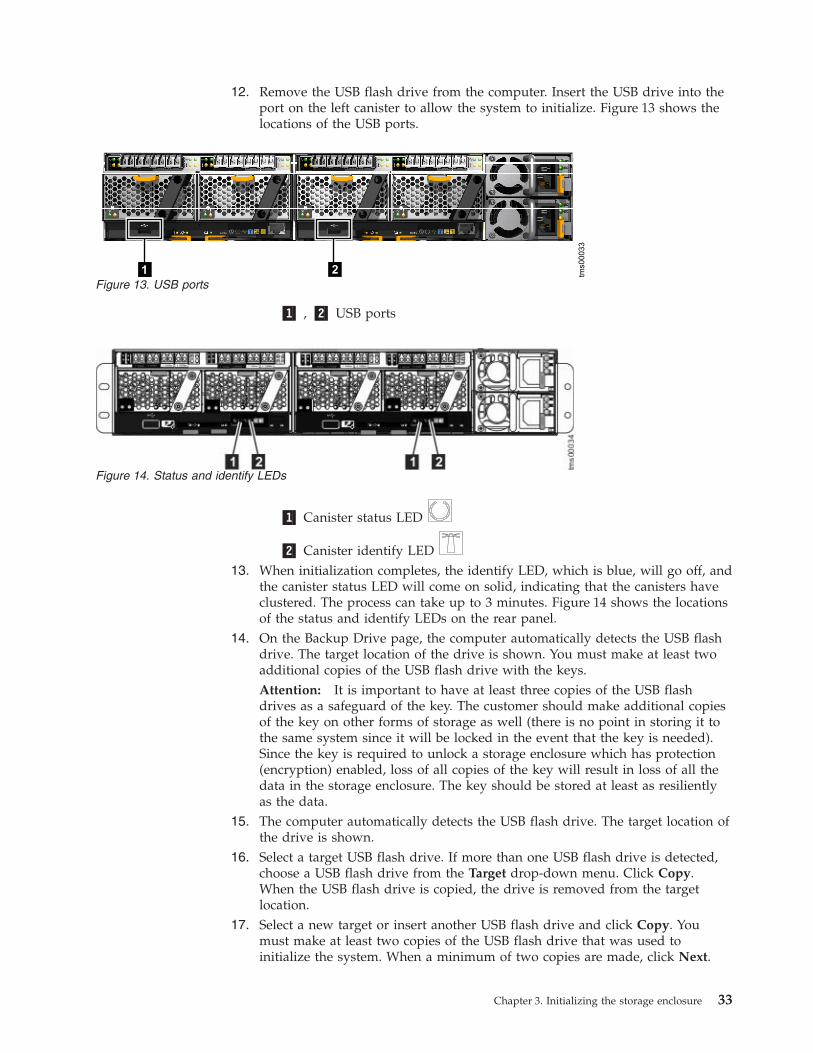
�1� , �2� USB ports
�1� Canister status LED
21 tms00033
Figure 11. USB ports
Figure 12. Status and identify LEDs
30 FlashSystem 840: Installation Guide

�2� Canister identify LED11. When initialization completes, the identify LED, which is blue, will go off, and
the canister status LED will come on solid, indicating that the canisters haveclustered. The process can take up to 3 minutes. Figure 12 on page 30 showsthe locations of the status and identify LEDs on the rear panel.
12. When the system has initialized, remove the USB flash drive from the canister.Reinsert the USB flash drive into a USB port on the computer.
13. On the Backup Drive page, the computer automatically detects the USB flashdrive. The target location of the drive is shown. You must make at least twoadditional copies of the USB flash drive with the keys.Attention: It is important to have at least three copies of the USB flashdrives as a safeguard of the key. The customer should make additional copiesof the key on other forms of storage as well (there is no point in storing it tothe same system since it will be locked in the event that the key is needed).Since the key is required to unlock a storage enclosure which has protection(encryption) enabled, loss of all copies of the key will result in loss of all thedata in the storage enclosure. The key should be stored at least as resilientlyas the data.
14. The computer automatically detects the USB flash drive. The target location ofthe drive is shown.
15. Select a target USB flash drive. If more than one USB flash drive is detected,choose a USB flash drive from the Target drop-down menu. Click Copy.When the USB flash drive is copied, the drive is removed from the targetlocation.
16. Select a new target or insert another USB flash drive and click Copy. Youmust make at least two copies of the USB flash drive that was used toinitialize the system. When a minimum of two copies are made, click Next.
17. If the system initialization finished successfully, click Finish. The systemmanagement GUI is displayed.
18. Log in with user name superuser and password passw0rd.
Note: The 0 character in the password is a zero, not the letter O.19. Follow the on-screen instructions to begin setting up the system.20. After the Service Support Representative (SSR) verifies the initial
configuration, the customer will complete the setup process using the SystemSetup wizard, including:v Entering the system namev Entering the system date and time, or entering the address of an NTP
serverv Creating one large array that includes all flash modules
21. After completing the wizard, the storage enclosure is initialized, initiallyconfigured, and ready for the customer to perform configuration tasks, such asentering users, creating LUNs, and creating host mappings to limit access tothe LUNs.
Initializing the storage enclosure with a Linux computerTo initialize a new storage enclosure with a Linux computer, use the USB flashdrive initialization tool that was included with the storage enclosure.
Chapter 3. Initializing the storage enclosure 31

Before you beginv Begin this procedure after the physical installation of the storage enclosure is
finished.v The computer used to initialize the storage enclosure must have a USB port and
a network connection to the storage enclosure.v If this computer does not have a network connection to the storage enclosure, go
to the workstation you will use to configure the storage enclosure. Start asupported browser and direct the browser to the management address for thestorage enclosure.
About this task
This procedure is valid for Red Hat Enterprise Server 5 or Ubuntu desktop 11.04.Use this procedure only when you initialize a new storage enclosure.
Procedure
To initialize the system, complete the following steps.1. Gather the information that you will use to configure the system.
v You must have the IP network address that you will use to manage thesystem.– IP address– Subnet mask– Gateway
v Call Home contact information and the address of a simple mail transferprotocol (SMTP) server for sending automated notifications of alerts. Whenthis Call Home feature is enabled, the system notifies IBM of system healthand issues.
v You can also enter the IP address of a Network Time Protocol (NTP) serverfor automated setting of date and time.
2. Locate the three USB flash drives that were included with the storageenclosure in the documentation package.Attention: All three USB flash drives s contain the initialization tool and ascript that is used to generate the encryption key.
3. Insert the USB flash drive into a USB port on the computer.4. Open a terminal window.5. Locate the root directory of the USB flash drive. It is usually located in the
/media/ directory. If an automatic mount system is used, the root directorycan be located by typing the mount command.
6. Type: sh InitTool.sh The initialization tool wizard starts.7. On the Tasks page, select Yes to configure a new system. If you already
initialized the system but are unable to access it, select No. If you select No,more options become available.
8. On the Encryption page, select Yes to indicate that you intend to activateencryption for the system.
9. On the Management IP page, enter the IP address, Subnet mask, andGateway information. Click Apply and Next.
10. When prompted to do so, enter the Call Home information.11. Before you proceed, ensure that the system is powered on.
32 FlashSystem 840: Installation Guide
12. Remove the USB flash drive from the computer. Insert the USB drive into theport on the left canister to allow the system to initialize. Figure 13 shows thelocations of the USB ports.
�1� , �2� USB ports
�1� Canister status LED
�2� Canister identify LED13. When initialization completes, the identify LED, which is blue, will go off, and
the canister status LED will come on solid, indicating that the canisters haveclustered. The process can take up to 3 minutes. Figure 14 shows the locationsof the status and identify LEDs on the rear panel.
14. On the Backup Drive page, the computer automatically detects the USB flashdrive. The target location of the drive is shown. You must make at least twoadditional copies of the USB flash drive with the keys.Attention: It is important to have at least three copies of the USB flashdrives as a safeguard of the key. The customer should make additional copiesof the key on other forms of storage as well (there is no point in storing it tothe same system since it will be locked in the event that the key is needed).Since the key is required to unlock a storage enclosure which has protection(encryption) enabled, loss of all copies of the key will result in loss of all thedata in the storage enclosure. The key should be stored at least as resilientlyas the data.
15. The computer automatically detects the USB flash drive. The target location ofthe drive is shown.
16. Select a target USB flash drive. If more than one USB flash drive is detected,choose a USB flash drive from the Target drop-down menu. Click Copy.When the USB flash drive is copied, the drive is removed from the targetlocation.
17. Select a new target or insert another USB flash drive and click Copy. Youmust make at least two copies of the USB flash drive that was used toinitialize the system. When a minimum of two copies are made, click Next.
21 tms00033
Figure 13. USB ports
Figure 14. Status and identify LEDs
Chapter 3. Initializing the storage enclosure 33

18. If the system initialization finished successfully, click Finish. The systemmanagement GUI is displayed.
19. Log in with user name superuser and password passw0rd.
Note: The 0 character in the password is a zero, not the letter O.20. Follow the on-screen instructions to begin setting up the system.21. After the Service Support Representative (SSR) verifies the initial
configuration, the customer will complete the setup process using the SystemSetup wizard, including:v Entering the system namev Entering the system date and time, or entering the address of an NTP
serverv Creating one large array that includes all flash modules
22. After completing the wizard, the storage enclosure is initialized, initiallyconfigured, and ready for the customer to perform configuration tasks, such asentering users, creating LUNs, and creating host mappings to limit access tothe LUNs.
Initializing the storage enclosure with an Apple Macintoshcomputer
To initialize the new storage enclosure with an Apple Macintosh computer, use theUSB flash drive initialization tool that was included with the storage enclosure.
Before you beginv Begin this procedure after the physical installation of the storage enclosure is
finished.v The computer used to initialize the storage enclosure must have a USB port and
a network connection to the storage enclosure.v If this computer does not have a network connection to the storage enclosure, go
to the workstation you will use to configure the storage enclosure. Start asupported browser and direct the browser to the management address for thestorage enclosure.
About this task
This procedure is valid for Apple MacOS X 10.7. Use this procedure only whenyou initialize a new storage enclosure.
Procedure
To initialize the system, complete the following steps.1. Gather the information that you will use to configure the system.
v You must have the IP network address that you will use to manage thesystem.– IP address– Subnet mask– Gateway
v Call Home contact information and the address of a simple mail transferprotocol (SMTP) server for sending automated notifications of alerts. Whenthis Call Home feature is enabled, the system notifies IBM of system healthand issues.
34 FlashSystem 840: Installation Guide
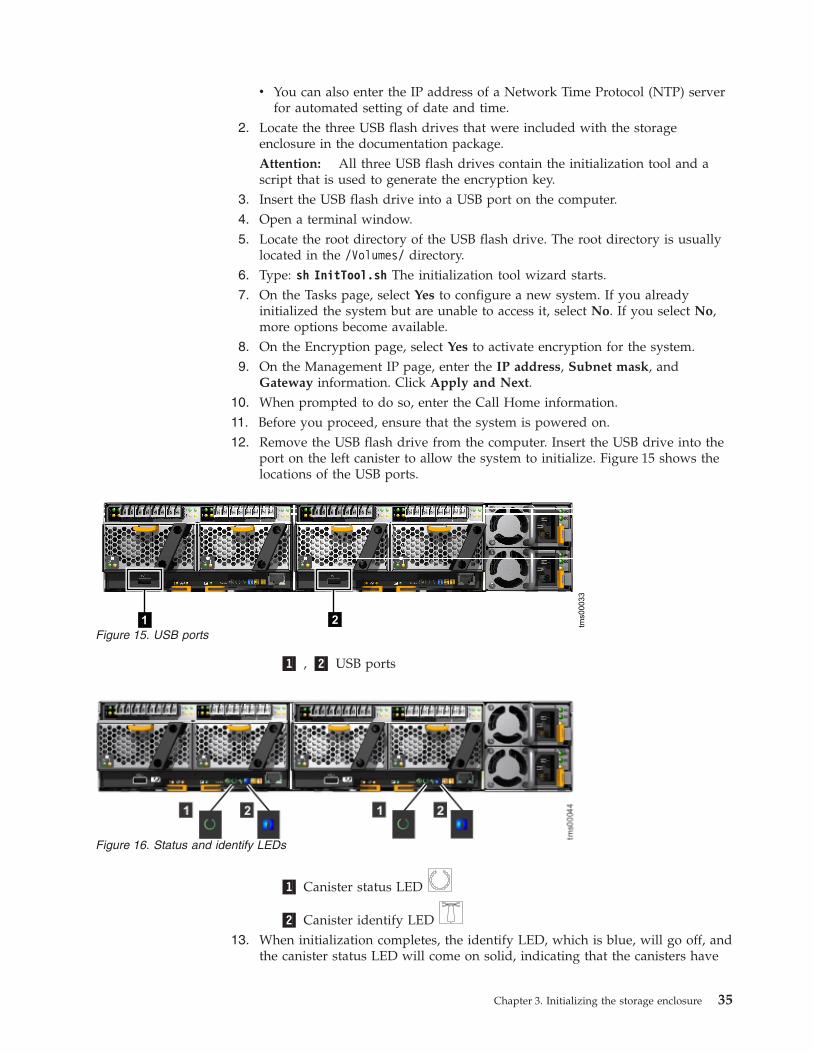
v You can also enter the IP address of a Network Time Protocol (NTP) serverfor automated setting of date and time.
2. Locate the three USB flash drives that were included with the storageenclosure in the documentation package.Attention: All three USB flash drives contain the initialization tool and ascript that is used to generate the encryption key.
3. Insert the USB flash drive into a USB port on the computer.4. Open a terminal window.5. Locate the root directory of the USB flash drive. The root directory is usually
located in the /Volumes/ directory.6. Type: sh InitTool.sh The initialization tool wizard starts.7. On the Tasks page, select Yes to configure a new system. If you already
initialized the system but are unable to access it, select No. If you select No,more options become available.
8. On the Encryption page, select Yes to activate encryption for the system.9. On the Management IP page, enter the IP address, Subnet mask, and
Gateway information. Click Apply and Next.10. When prompted to do so, enter the Call Home information.11. Before you proceed, ensure that the system is powered on.12. Remove the USB flash drive from the computer. Insert the USB drive into the
port on the left canister to allow the system to initialize. Figure 15 shows thelocations of the USB ports.
�1� , �2� USB ports
�1� Canister status LED
�2� Canister identify LED13. When initialization completes, the identify LED, which is blue, will go off, and
the canister status LED will come on solid, indicating that the canisters have
21 tms00033
Figure 15. USB ports
Figure 16. Status and identify LEDs
Chapter 3. Initializing the storage enclosure 35
clustered. The process can take up to 3 minutes. Figure 16 on page 35 showsthe locations of the status and identify LEDs on the rear panel.
14. On the Backup Drive page, the computer automatically detects the USB flashdrive. The target location of the drive is shown. You must make at least twoadditional copies of the USB flash drive with the keys.Attention: It is important to have at least three copies of the USB flashdrives as a safeguard of the key. The customer should make additional copiesof the key on other forms of storage as well (there is no point in storing it tothe same system since it will be locked in the event that the key is needed).Since the key is required to unlock a storage enclosure which has protection(encryption) enabled, loss of all copies of the key will result in loss of all thedata in the storage enclosure. The key should be stored at least as resilientlyas the data.
15. The computer automatically detects the USB flash drive. The target location ofthe drive is shown.
16. Select a target USB flash drive. If more than one USB flash drive is detected,choose a USB flash drive from the Target drop-down menu. Click Copy.When the USB flash drive is copied, the drive is removed from the targetlocation.
17. Select a new target or insert another USB flash drive and click Copy. Make atleast two copies of the USB flash drive that was used to initialize the system.When a minimum of two copies are made, click Next.
18. If the system initialization finished successfully, click Finish. The systemmanagement GUI is displayed.
19. Log in with user name superuser and password passw0rd.
Note: The 0 character in the password is a zero, not the letter O.20. Follow the on-screen instructions to begin setting up the system.21. After the Service Support Representative (SSR) verifies the initial
configuration, the customer will complete the setup process using the SystemSetup wizard, including:v Entering the system namev Entering the system date and time, or entering the address of an NTP
serverv Creating one large array that includes all flash modules
22. After completing the wizard, the storage enclosure is initialized, initiallyconfigured, and ready for the customer to perform configuration tasks, such asentering users, creating LUNs, and creating host mappings to limit access tothe LUNs.
Initializing a storage enclosure without an encryption licenseLearn how to initialize a storage enclosure that does not have an encryptionlicense.
Use the supplied USB flash drive to initialize the storage enclosure. After youinitialize the storage enclosure, access the management GUI to finish theconfiguration procedures.
The steps for initializing a new storage enclosure vary and depend on theoperating system of the computer being used.
36 FlashSystem 840: Installation Guide

Initializing the storage enclosure with a Microsoft Windowscomputer
To initialize a new storage enclosure with a Microsoft Windows computer, use theUSB flash drive initialization tool that was included with the storage enclosure.
Before you beginv Begin this procedure after the physical installation of the storage enclosure is
finished.v The computer used to initialize the storage enclosure must have a USB port and
a network connection to the storage enclosure.v If this computer does not have a network connection to the storage enclosure, go
to the workstation you will use to configure the storage enclosure. Start asupported browser and direct the browser to the management address for thestorage enclosure.
About this task
This procedure is valid for Microsoft Windows 7 (64-bit) or XP (32-bit). Use thisprocedure only when you initialize a new storage enclosure.
Procedure1. Gather the information that you will use to configure the system.
v You must have the IP network address that you will use to manage thesystem.– IP address– Subnet mask– Gateway
v Call Home contact information and the address of a simple mail transferprotocol (SMTP) server for sending automated notifications of alerts. Whenthis Call Home feature is enabled, the system notifies IBM of system healthand issues.
v You can also enter the IP address of a Network Time Protocol (NTP) serverfor automated setting of date and time.
2. Locate the USB flash drive that was included with the enclosuredocumentation package.
3. Insert the USB flash drive into a USB port on the computer.4. To start the initialization tool, open the USB flash drive and double-click
InitTool.bat. The initialization tool wizard starts.5. On the Tasks page, select Yes to configure a new system. If you already
initialized the system but are unable to access it, select No. If you select No,more options become available.
6. On the Encryption page, select No to indicate that you do not intend toactivate encryption on the system.
7. On the Management IP page, enter the IP address, Subnet mask, andGateway information. Click Apply and Next.
8. When prompted to do so, enter the Call Home information.9. Before you proceed, ensure that the system is powered on.
10. Remove the USB flash drive from the computer. Insert the USB drive into theport on the left canister to allow the system to initialize. Figure 17 on page 38
Chapter 3. Initializing the storage enclosure 37

shows the locations of the USB ports.
�1� , �2� USB ports
�1� Canister status LED
�2� Canister identify LED11. When initialization completes, the identify LED, which is blue, will go off, and
the canister status LED will come on solid, indicating that the canisters haveclustered. The process can take up to 3 minutes. Figure 18 shows the locationsof the status and identify LEDs on the rear panel.
12. If the system initialization finished successfully, click Finish. The systemmanagement GUI is displayed.
13. Log in with user name superuser and password passw0rd.
Note: The 0 character in the password is a zero, not the letter O.14. Follow the on-screen instructions to begin setting up the system.15. After the Service Support Representative (SSR) verifies the initial
configuration, the customer will complete the setup process using the SystemSetup wizard, including:v Entering the system namev Entering the system date and time, or entering the address of an NTP
serverv Creating one large array that includes all flash modules
16. After completing the wizard, the storage enclosure is initialized, initiallyconfigured, and ready for the customer to perform configuration tasks, such asentering users, creating LUNs, and creating host mappings to limit access tothe LUNs.
21 tms00033
Figure 17. USB ports
Figure 18. Status and identify LEDs
38 FlashSystem 840: Installation Guide

Initializing the storage enclosure with a Linux computerTo initialize a new storage enclosure with a Linux computer, use the USB flashdrive initialization tool that was included with the storage enclosure.
Before you beginv Begin this procedure after the physical installation of the storage enclosure is
finished.v The computer must have a USB port and a network connection to the storage
enclosure.v If this computer does not have a network connection to the storage enclosure, go
to the workstation you will use to configure the storage enclosure. Start asupported browser and direct the browser to the management address for thestorage enclosure.
About this task
This procedure is valid for Red Hat Enterprise Server 5 or Ubuntu desktop 11.04.Use this procedure only when you initialize a new storage enclosure.
Procedure1. Gather the information that you will use to configure the system.
v You must have the IP network address that you will use to manage thesystem.– IP address– Subnet mask– Gateway
v Other information is optional, but useful for enabling more capabilities.– The IP address of a Network Time Protocol (NTP) server for automated
setting of date and time.– The IP address of a simple mail transfer protocol (SMTP) server for
sending automated notifications of alerts. When this Call Home feature isenabled, the system notifies IBM of system health and failures.
2. Locate the USB flash drive that was included with the system in thedocumentation package.
3. Insert the USB flash drive into a USB port on the computer.4. Open a terminal window.5. Locate the root directory of the USB flash drive. It is usually located in the
/media/ directory. If an automatic mount system is used, the root directorycan be located by typing the mount command.
6. Type: sh InitTool.sh The initialization tool wizard starts.7. On the Tasks page, select Yes to configure a new system. If you already
initialized the system but are unable to access it, select No. If you select No,more options become available.
8. On the Encryption page, select No to indicate that you do not intend toactivate encryption on the system.
9. On the Management IP page, enter the IP address, Subnet mask, andGateway information. Click Apply and Next.
10. Before you proceed, ensure that the system is powered on.11. Remove the USB flash drive from the computer. Insert the USB drive into the
port on the left canister to allow the system to initialize. Figure 19 on page 40
Chapter 3. Initializing the storage enclosure 39
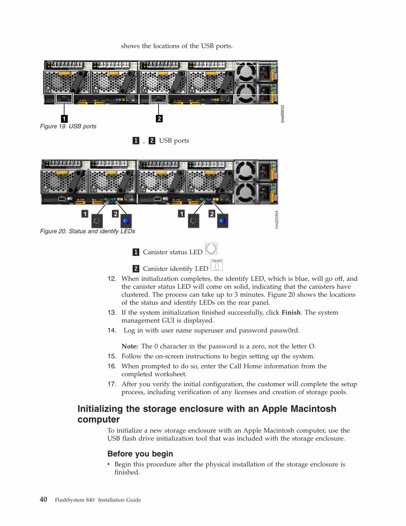
shows the locations of the USB ports.
�1� , �2� USB ports
�1� Canister status LED
�2� Canister identify LED12. When initialization completes, the identify LED, which is blue, will go off, and
the canister status LED will come on solid, indicating that the canisters haveclustered. The process can take up to 3 minutes. Figure 20 shows the locationsof the status and identify LEDs on the rear panel.
13. If the system initialization finished successfully, click Finish. The systemmanagement GUI is displayed.
14. Log in with user name superuser and password passw0rd.
Note: The 0 character in the password is a zero, not the letter O.15. Follow the on-screen instructions to begin setting up the system.16. When prompted to do so, enter the Call Home information from the
completed worksheet.17. After you verify the initial configuration, the customer will complete the setup
process, including verification of any licenses and creation of storage pools.
Initializing the storage enclosure with an Apple Macintoshcomputer
To initialize a new storage enclosure with an Apple Macintosh computer, use theUSB flash drive initialization tool that was included with the storage enclosure.
Before you beginv Begin this procedure after the physical installation of the storage enclosure is
finished.
21 tms00033
Figure 19. USB ports
Figure 20. Status and identify LEDs
40 FlashSystem 840: Installation Guide

v To complete the initialization procedure, the computer must have a USB portand a network connection to the storage enclosure.
v If the computer does not have a network connection to the storage enclosure, goto the computer you use to configure the system. Start a supported browser anddirect the browser to the management address you specified for the system.
About this task
This procedure is valid for Apple MacOS X 10.7. Use this procedure only whenyou initialize a new storage enclosure.
Procedure1. Gather the information that you will use to configure the system.
v You must have the IP network address that you will use to manage thesystem.– IP address– Subnet mask– Gateway
v Other information is optional, but useful for enabling more capabilities.– The IP address of a Network Time Protocol (NTP) server for automated
setting of date and time– The IP address of a simple mail transfer protocol (SMTP) server for
sending automated notifications of alerts. When this Call Home feature isenabled, the system notifies IBM of system health and failures.
2. Locate the USB flash drive that was included with the documentationpackage.
3. Insert the USB flash drive into a USB port on the computer.4. Open a terminal window.5. Locate the root directory of the USB flash drive. The root directory is usually
located in the /Volumes/ directory.6. Type: sh InitTool.sh The initialization tool wizard starts.7. On the Tasks page, select Yes to configure a new system. If you already
initialized the system but are unable to access it, select No. If you select No,more options become available.
8. On the Encryption page, select No to indicate that you do not intend toactivate encryption on the system.
9. On the Management IP page, enter the IP address, Subnet mask, andGateway information. Click Apply and Next.
10. Before you proceed, ensure that the system is powered on.11. Remove the USB flash drive from the computer. Insert the USB drive into the
port on the left canister to allow the system to initialize. Figure 21 on page 42shows the locations of the USB ports.
Chapter 3. Initializing the storage enclosure 41

�1� , �2� USB ports
�1� Canister status LED
�2� Canister identify LED12. When initialization completes, the identify LED, which is blue, will go off, and
the canister status LED will come on solid, indicating that the canisters haveclustered. The process can take up to 3 minutes. Figure 22 shows the locationsof the status and identify LEDs on the rear panel.
13. If the system initialization finished successfully, click Finish. The storageenclosure management GUI is displayed.
14. Log in with user name superuser and password passw0rd.
Note: The 0 character in the password is a zero, not the letter O.15. Follow the on-screen instructions to begin setting up the system.16. When prompted to do so, enter the Call Home information from the
completed worksheet.17. After you verify the initial configuration, the customer will complete the setup
process, including verification of any licenses and creation of storage pools.
21 tms00033
Figure 21. USB ports
Figure 22. Status and identify LEDs
42 FlashSystem 840: Installation Guide

Chapter 4. Upgrading the storage enclosure hardware
You can upgrade the storage enclosure hardware by adding or replacingcomponents.
Installing additional flash modulesLearn how to properly add flash modules to the enclosure.
About this task
Attention: The additional flash modules must match the capacity of all otherflash modules in the system. Do not mix flash modules with different capacities.
Attention: To avoid loss of all data on the flash modules, you must back up all ofyour data before you install the additional flash modules. This procedure removesthe current array from the existing flash modules.
To add additional flash modules, complete the following steps:
Procedure1. Read the safety precautions in the IBM Systems Safety Notices. These guidelines
help you safely work with the system.2. Shut down all host I/O to the system.3. To avoid loss of the data on the array, you must back up all information on
the array before proceeding.4. Before you install the flash modules, you must remove the existing array. To
view a list of the VDisks in the array, enter the lsvdisk command.5. To delete the VDisks, enter the rmvdisk -force id CLI command for each
VDisk, where id is the id number of the VDisk being deleted.6. To verify that the VDisks were deleted, enter the lsvdisk command.7. To remove the array, enter the rmarray command.8. To verify that the array was deleted, enter the lsarray command.
You are now ready to add the new flash modules. Flash modules are installedbased on the configuration guidelines in Table 16. For optimal cooling of theenclosure, if there are fewer than 12 flash modules, they are installedbeginning in the center pair of slots and added on both sides until all 12 slotsare populated.
Table 16. Supported flash module configurations
NumberofflashmodulesRAID
Slot1
Slot2
Slot3
Slot4
Slot5
Slot6
Slot7
Slot8
Slot9
Slot10
Slot11
Slot12
2 RAID0
X X
4 RAID0, 5
X X X X
8 RAID0, 5
X X X X X X X X
© Copyright IBM Corp. 2014, 43

Table 16. Supported flash module configurations (continued)
NumberofflashmodulesRAID
Slot1
Slot2
Slot3
Slot4
Slot5
Slot6
Slot7
Slot8
Slot9
Slot10
Slot11
Slot12
12 RAID0, 5
X X X X X X X X X X X X
9. Based on these guidelines, identify the slots in which you are installing thenew flash modules.
10. Remove the flash module blanks from each of the slots that you identified instep 9.
11. To install the additional flash modules, complete the following steps.a. Press the latch at the top of the handle on the flash module, which is
shown in Figure 23, and open the handle.
�1� Release latch on handleb. Slide the flash module into the slot until the handle starts to move.c. Finish inserting the module by closing the handle until the latch clicks into
place.d. Repeat steps a though c to install the remaining flash modules.
12. To verify that the drives are in a candidate state, enter the lsdrive command.13. To create a new array that includes all the flash modules, enter the mkarray
-level raid n command, where n is the RAID level of the array (5 or 0). Itmight take several minutes to initialize the array.
14. Re-create all VDisk and host mappings to restore the original storageconfiguration.
15. Restore the data to the array.
Figure 23. Flash module
44 FlashSystem 840: Installation Guide

Adding additional SFPsLearn how to add additional SFPs to the storage enclosure.
Before you begin
Note: You must have the correct type and speed of small form-factor pluggable(SFP) transceivers. Using the wrong SFP transceiver might result in loss of dataaccess.
Be careful when you are replacing the hardware components that are located in theback of the system that you do not inadvertently disturb or remove any cables thatyou are not instructed to remove.
Ensure that you are aware of the procedures for handling static-sensitive devices.
About this task
To install additional SFP transceivers, complete the following steps:
Procedure1. Read the safety precautions in the IBM Systems Safety Notices. These guidelines
help you safely work with the system.2. Shut down all host I/O to the enclosure.3. To install a new SFP transceiver, complete the following steps.
a. If used, open the release handle on the SFP transceiver.b. Push the new SFP transceiver into the aperture in the interface card until it
stops.c. If the SFP transceiver uses a release handle, close the handle to secure the
SFP.d. Gently pull the SFP transceiver. If it is installed correctly, it does not move
from its aperture.4. Repeat step 3 as necessary to install the remaining SFP transceivers.5. Connect Fibre Channel cables to the new SFP transceivers.6. To reset the interface cards where you installed the new SFP transceivers, enter
the svctask maintenance -action reset -canister x -adapter y CLIcommand, where x and y are the numbers of the canister and interface cards.
Chapter 4. Upgrading the storage enclosure hardware 45

46 FlashSystem 840: Installation Guide

Appendix A. Accessibility features for IBM FlashSystem 840
Accessibility features help users who have a disability, such as restricted mobilityor limited vision, to use information technology products successfully.
Accessibility features
These are the major accessibility features for the IBM FlashSystem 840:v You can use screen-reader software and a digital speech synthesizer to hear what
is displayed on the screen. PDF documents have been tested using AdobeReader version 7.0. HTML documents have been tested using JAWS version 13.0.
v This product uses standard Windows navigation keys.v Interfaces are commonly used by screen readers.v Keys are discernible by touch, but do not activate just by touching them.v Industry-standard devices, ports, and connectors.v You can attach alternative input and output devices.
The system Information Center and its related publications areaccessibility-enabled. .
Keyboard navigation
You can use keys or key combinations to perform operations and initiate menuactions that can also be done through mouse actions. You can navigate theInformation Center from the keyboard by using the shortcut keys for your browseror screen-reader software. See your browser or screen-reader software Help for alist of shortcut keys that it supports.
IBM and accessibility
See the IBM Human Ability and Accessibility Center for more information aboutthe commitment that IBM has to accessibility.
© Copyright IBM Corp. 2014, 47

48 FlashSystem 840: Installation Guide

Appendix B. Where to find the Statement of Limited Warranty
The Statement of Limited Warranty is available in both hardcopy format and in theInformation Center.
The Statement of Limited Warranty is shipped hardcopy with your product. It isalso available at: “IBM FlashSystem 840 library and related publications” on pagexix.
© Copyright IBM Corp. 2014, 49

50 FlashSystem 840: Installation Guide

Notices
This information was developed for products and services offered in the U.S.A.
IBM may not offer the products, services, or features discussed in this document inother countries. Consult your local IBM representative for information on theproducts and services currently available in your area. Any reference to an IBMproduct, program, or service is not intended to state or imply that only that IBMproduct, program, or service may be used. Any functionally equivalent product,program, or service that does not infringe any IBM intellectual property right maybe used instead. However, it is the user's responsibility to evaluate and verify theoperation of any non-IBM product, program, or service.
IBM may have patents or pending patent applications covering subject matterdescribed in this document. The furnishing of this document does not grant youany license to these patents. You can send license inquiries, in writing, to:
IBM Director of LicensingIBM CorporationNorth Castle DriveArmonk, NY 10504-1785U.S.A.
For license inquiries regarding double-byte character set (DBCS) information,contact the IBM Intellectual Property Department in your country or sendinquiries, in writing, to:
Intellectual Property LicensingLegal and Intellectual Property LawIBM Japan, Ltd.19-21, Nihonbashi-Hakozakicho, Chuo-kuTokyo 103-8510, Japan
The following paragraph does not apply to the United Kingdom or any othercountry where such provisions are inconsistent with local law:INTERNATIONAL BUSINESS MACHINES CORPORATION PROVIDES THISPUBLICATION "AS IS" WITHOUT WARRANTY OF ANY KIND, EITHEREXPRESS OR IMPLIED, INCLUDING, BUT NOT LIMITED TO, THE IMPLIEDWARRANTIES OF NON-INFRINGEMENT, MERCHANTABILITY OR FITNESSFOR A PARTICULAR PURPOSE. Some states do not allow disclaimer of express orimplied warranties in certain transactions, therefore, this statement may not applyto you.
This information could include technical inaccuracies or typographical errors.Changes are periodically made to the information herein; these changes will beincorporated in new editions of the publication. IBM may make improvementsand/or changes in the product(s) and/or the program(s) described in thispublication at any time without notice.
Any references in this information to non-IBM Web sites are provided forconvenience only and do not in any manner serve as an endorsement of those Websites. The materials at those Web sites are not part of the materials for this IBMproduct and use of those Web sites is at your own risk.
© Copyright IBM Corp. 2014, 51

IBM may use or distribute any of the information you supply in any way itbelieves appropriate without incurring any obligation to you.
Licensees of this program who wish to have information about it for the purposeof enabling: (i) the exchange of information between independently createdprograms and other programs (including this one) and (ii) the mutual use of theinformation which has been exchanged, should contact:
IBM CorporationAlmaden Research650 Harry RoadBldg 80, D3-304, Department 277San Jose, CA 95120-6099U.S.A.
Such information may be available, subject to appropriate terms and conditions,including in some cases, payment of a fee.
The licensed program described in this document and all licensed materialavailable for it are provided by IBM under terms of the IBM Customer Agreement,IBM International Program License Agreement or any equivalent agreementbetween us.
Any performance data contained herein was determined in a controlledenvironment. Therefore, the results obtained in other operating environments mayvary significantly. Some measurements may have been made on development-levelsystems and there is no guarantee that these measurements will be the same ongenerally available systems. Furthermore, some measurements may have beenestimated through extrapolation. Actual results may vary. Users of this documentshould verify the applicable data for their specific environment.
Information concerning non-IBM products was obtained from the suppliers ofthose products, their published announcements or other publicly available sources.IBM has not tested those products and cannot confirm the accuracy ofperformance, compatibility or any other claims related to non-IBM products.Questions on the capabilities of non-IBM products should be addressed to thesuppliers of those products.
All statements regarding IBM's future direction or intent are subject to change orwithdrawal without notice, and represent goals and objectives only.
All IBM prices shown are IBM's suggested retail prices, are current and are subjectto change without notice. Dealer prices may vary.
This information is for planning purposes only. The information herein is subject tochange before the products described become available.
This information contains examples of data and reports used in daily businessoperations. To illustrate them as completely as possible, the examples include thenames of individuals, companies, brands, and products. All of these names arefictitious and any similarity to the names and addresses used by an actual businessenterprise is entirely coincidental.
COPYRIGHT LICENSE:
52 FlashSystem 840: Installation Guide
This information contains sample application programs in source language, whichillustrate programming techniques on various operating platforms. You may copy,modify, and distribute these sample programs in any form without payment toIBM, for the purposes of developing, using, marketing or distributing applicationprograms conforming to the application programming interface for the operatingplatform for which the sample programs are written. These examples have notbeen thoroughly tested under all conditions. IBM, therefore, cannot guarantee orimply reliability, serviceability, or function of these programs. The sampleprograms are provided "AS IS", without warranty of any kind. IBM shall not beliable for any damages arising out of your use of the sample programs.
If you are viewing this information softcopy, the photographs and colorillustrations may not appear.
TrademarksIBM, the IBM logo, and ibm.com® are trademarks or registered trademarks ofInternational Business Machines Corp., registered in many jurisdictions worldwide.Other product and service names might be trademarks of IBM or other companies.A current list of IBM trademarks is available on the web at Copyright andtrademark information at www.ibm.com/legal/copytrade.shtml.
Adobe, the Adobe logo, PostScript, and the PostScript logo are either registeredtrademarks or trademarks of Adobe Systems Incorporated in the United States,and/or other countries.
Microsoft, Windows, and the Windows logo are trademarks of MicrosoftCorporation in the United States, other countries, or both.
Other product and service names might be trademarks of IBM or other companies.
Notices 53

54 FlashSystem 840: Installation Guide

Index
Aaccessibility 47
repeat rateup and down buttons 47
accessingpublications 47
addingflash module 43SFPs 45
Bbrowsers
See web browsers
Ccaution ixcaution notices xcharts and tables
cable connection tables 1configuration data table 4
configurationplanning 4web browsers
settings 6connecting
management port Ethernet cables 21power cords 25
Ddanger ixdanger notices xiii
Eenclosure 16environmental notices ix, xviiEthernet 21
FFC 23FCoE 23Fibre Channel 23Fibre Channel over Ethernet 23flash module
adding 43
Hhelp xxii
IIEC 60950-1 ixInfiniBand 23information center xixinformation help xxiiinitializing the storage enclosure
Apple Macintosh 34, 40Linux 39Micosoft Windows 29Microsoft Windows 37
initializing the systemLinux 32
installation 9
Kkeyboards
accessibility features 47
Llabels ixlibrary
related publications xix
Nnavigation
accessibility 47notices ix
environmental ix, xviisafety ix
Ppackaging slip 12planning
configuration data table 4publications
accessing 47
Rrelated information xixrequirements
TCP/IP 5
Ssafety ix
caution notices xdanger notices xiiienvironmental notices ix
safety information labels ixsafety notices ix
sound pressure xviiSFPs
adding 45
shortcut keyskeyboard 47
sound pressuresafety notices xvii
Statement of Limited Warranty, Where tofind the 49
static-sensitive devices xvistorage enclosure
hardware upgrades 43support rails 12
TTCP/IP
requirements 5technical assistance xxiitrademarks 53
Uupgrading hardware
storage enclosure 43USB flash drive
initializing the storage enclosureApple Macintosh 40encryption 29, 34Linux 39Microsoft Windows 37
initializing the systemencryption 32
Wweb browsers
configuring 6requirements 6
websites xxii
© Copyright IBM Corp. 2014, 55

56 FlashSystem 840: Installation Guide


����
Printed in USA
GI13-2871-01