flat linear induction pumps - creative … 1 – simplified cross section of flat linear induction...
TRANSCRIPT

Creative Engineers, Inc. Phone (443) 807-1202 PO Box 206 Phoenix MD 21131 Fax (410) 683-9707 www.creativeengineers.com [email protected]
Creative Engineers, Inc. Page 1 of 7
FLATLINEARINDUCTIONPUMPS
www.CreativeEngineers.com

2
TABLEOFCONTENTS
1. PRINCIPLE OF OPERATION ...................................................................................................................................... 3
2. DESCRIPTION ............................................................................................................................................................... 4
3. APPLICATION ............................................................................................................................................................... 6
4. OPERATION................................................................................................................................................................... 7
LISTOFDRAWINGSANDFIGURES Figure 1 – Simplified Cross Section of Flat Linear Induction Pump Figure 2 – Simplified diagram for Field, Current, and Flow Figure 3 – Performance Curve

3
1.PRINCIPLEOFOPERATION The Flat Linear Induction Pumps (FLIP) work by setting up a magnetic field normal to
the direction of liquid flow and inducing a current in the metal which then produces a pump
force in the direction of flow based on F = J X B, where F is a motive force, J is a vector
representing current flow and B is the magnetic flux density created by the coils in the stator.
The pump operates on the voltage introduced in the liquid metal, when it is traveling at a
different velocity, generally lower, than the traveling magnetic field of the windings. This
induced voltage results in a circulating current, which reacts with the magnetic field. A force is
produced within the liquid metal in the direction of the traveling field and results in the
developed head. The developed head decreases as the velocity of the liquid metal increases (due
to lower slip resulting in a lower induced voltage) and reaches zero when the total force
developed on the liquid metal just balances the frictional, constriction and enlargement losses
within the pump.
When the pump is installed in a system, this balance will occur at a lower flow rate where
the developed head minus the frictional losses equals the pressure drop of the system for that
same flow rate. If the pump voltage is lowered, this balance will occur at still a lower flow rate;
likewise, if the voltage is increased, this balance will occur at a higher flow rate. However, the
velocity can never exceed that of the magnetic field. An autotransformer is recommended to
vary the voltage to the pump. The autotransformer provides a full wave voltage signal to the
pump for smooth operation.
Sufficient capacitors should be used to correct the power factor to better than 0.9 and
variable auto transformers used to control the flow from zero to full flow at whatever head is
desired, limited only by the maximum specified in the inquiry.
4
2.DESCRIPTION
The pump design consists of two essential parts, i.e., the flow tube with nozzle
connections and the end bars, and the three-phase magnetic field stator, which produces the
necessary field for reaction with induced currents in the liquid metal for the pumping action.
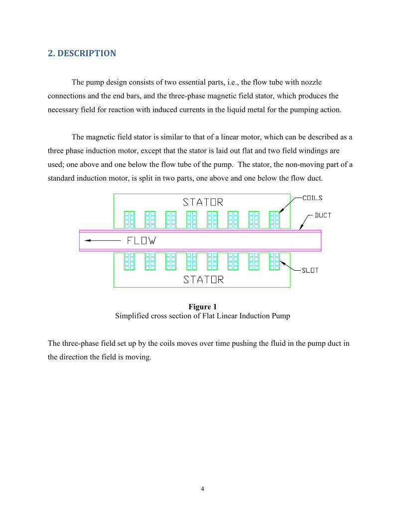
The magnetic field stator is similar to that of a linear motor, which can be described as a
three phase induction motor, except that the stator is laid out flat and two field windings are
used; one above and one below the flow tube of the pump. The stator, the non-moving part of a
standard induction motor, is split in two parts, one above and one below the flow duct.
Figure 1
Simplified cross section of Flat Linear Induction Pump
The three-phase field set up by the coils moves over time pushing the fluid in the pump duct in
the direction the field is moving.
5
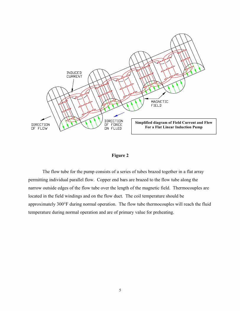
Figure 2
The flow tube for the pump consists of a series of tubes brazed together in a flat array
permitting individual parallel flow. Copper end bars are brazed to the flow tube along the
narrow outside edges of the flow tube over the length of the magnetic field. Thermocouples are
located in the field windings and on the flow duct. The coil temperature should be
approximately 300°F during normal operation. The flow tube thermocouples will reach the fluid
temperature during normal operation and are of primary value for preheating.
Simplified diagram of Field Current and Flow For a Flat Linear Induction Pump
6
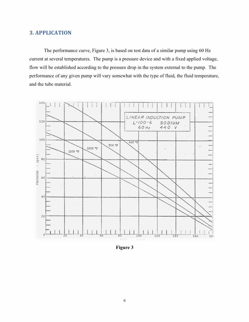
3.APPLICATION
The performance curve, Figure 3, is based on test data of a similar pump using 60 Hz
current at several temperatures. The pump is a pressure device and with a fixed applied voltage,
flow will be established according to the pressure drop in the system external to the pump. The
performance of any given pump will vary somewhat with the type of fluid, the fluid temperature,
and the tube material.
Figure 3

7
4.OPERATION
During loop start-up operations, the pump windings can be used to preheat the flow tube
for charging the system when using a liquid metal with a melting point above room temperature.
Pre-heating can be initiated by turning on the power to the pump at a low value, up to 50%. The
thermocouples on the flow tube will indicate the flow tube temperature and the preheat voltage
can be adjusted accordingly. If preheat temperatures below 400° are maintained, the blower
need not be used during the preheat cycle.
It is recommended that the liquid metal not be permitted to freeze within the pump. The
increase in volume on melting the liquid metal later could cause permanent damage to the flow
tube in the pump. If however, the liquid does freeze in the pump duct — all re-melting must be
performed in such a way as to allow the newly melted liquid to flow into an unrestricted area.