flat roof insulation - · pdf file4 2. the flat roof although the style and materials chosen...
TRANSCRIPT

Flat Roof Insulation Inverted Roof
Styrodur® C
Europe’s green insulation

2
Inh
alt
1 Long-standing Trust in Styrodur® C 3
2 The Flat Roof 4
2.1 Types of Flat Roofs/Definitions 5
3 Advantages of the Inverted Roof System 7
3.1 Advantages of Styrodur® C with Inverted Roofs 8
4 Applications 10
4.1 Substructure 10
4.2 Roof Waterproofing 10
4.3 Roof Drainage 10
4.4 Thermal Insulation Layer 11
4.5 Protective Layer 11
4.6 Protection Against Floating 12
4.7 Protection Against Wind Suction 12
5 Examples 13
5.1 Inverted Gravel Roof – Single-layer 13
5.2 Inverted Gravel Roof – Double-layer 13
5.3 Duo Roof 14
5.4 Plus Roof 15
5.5 Green Roof 16
5.6 Patio Roof 24
5.7 Parking Roof 25
6 General Processing Instructions 30
7 Application Recommendations for Styrodur C 31
3
1. Long-standing Trust in Styrodur® C
Styrodur® C is the green, extruded rigid polystyrene foam (XPS) developed by BASF more than 45 years ago. Today, Styrodur C is the synonym for XPS in Europe and—as a thermal insulation material—signifi-cantly contributes to climate protection by reducing CO2 emissions.
Styrodur C provides convincing advantages to specialized planners, architects, craftsmen, builders, and building material suppliers.
Environmental advantages:
Environment-friendly thanks to CO2 production processes with air as cell gas
Free of HFC Reduction of carbon dioxide emissions (CO2) due to
excellent insulating performance
Quality and safety advantages:
Safety based on decades of experience Protects the building construction from external
forces such as heat, cold, and humidity Comprehensive production control and quality
monitoring, documented by CE marking and Ü-sign Long-lasting: if correctly installed, Styrodur C out
lasts the life expectancy of the building construction
Structural-physical advantages:
Excellent insulation properties High compressive strength Low moisture absorption Resistance to aging and decay Fulfills all structural-physical and building
construction requirements in Europe’s various climate conditions
Processing advantages:
Low dead weight Simple and practical processing with
woodworking tools Can be installed in all weather conditions No dust hazardous to health during
mechanical processing Extensive product range Most diverse potential applications
Economic advantages:
Quick amortization of the insulation investment with rising energy costs
Reduction of energy costs for heating and cooling Increases the life span of the building and raises
the value of the structure Pan-European logistics with professional customer
service via local distributors
Lo
ng
-sta
nd
ing
Tru
st in
Sty
rod
ur®
C
4
2. The Flat Roof
Although the style and materials chosen for covering and sealing inclined and flat roof constructions have a high architectural significance, it is not solely the crea-tive aspects that shape the characteristics of a build-ing. Apart from the building’s functionality, economic aspects as well as structural design play a big part in choosing the right style, shape, and material for the roof. Regardless of any specific requirements, flat roofs are as capable of meeting the structural-physical and building construction requirements as steep roofs.
The structural design for inclined roofs as well as slightly sloped roofs with varying inclinations, or even zero-degree roofs, meet the current standards and regulations for thermal insulation and provide long-term, reliable protection against the effects of the weather. How “secure” a roof is does not depend on how steep the water-bearing layer incline is, rather on how well the planner and builder are informed of the specifics of the construction in question and how well they implement the requirements in the design and execution.
Inverted Roofs with Styrodur® C
In contrast with the conventional non-insulated roof with its waterproofing above the thermal insulation, special insulation materials such as BASF’s Styrodur® C may also be laid “inverted” on a flat roof. An increasing number of planners prefer the inverted roof and BASF’s Styrodur is an ideal insulation material for this system.
This brochure contains all the important planning and installation instructions for inverted roofs and explains the advantages of inverted roofs with Styrodur C.
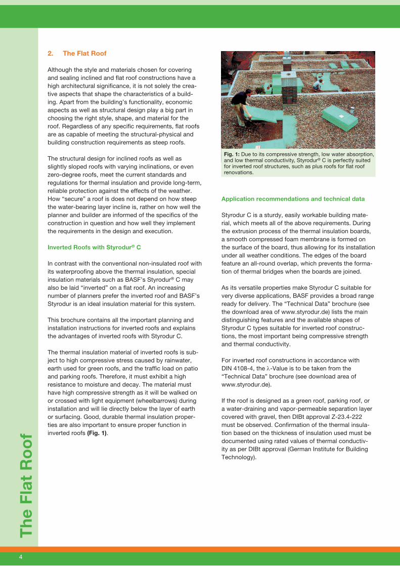
The thermal insulation material of inverted roofs is sub-ject to high compressive stress caused by rainwater, earth used for green roofs, and the traffic load on patio and parking roofs. Therefore, it must exhibit a high resistance to moisture and decay. The material must have high compressive strength as it will be walked on or crossed with light equipment (wheelbarrows) during installation and will lie directly below the layer of earth or surfacing. Good, durable thermal insulation proper-ties are also important to ensure proper function in inverted roofs (Fig. 1).
Application recommendations and technical data Styrodur C is a sturdy, easily workable building mate-rial, which meets all of the above requirements. During the extrusion process of the thermal insulation boards, a smooth compressed foam membrane is formed on the surface of the board, thus allowing for its installation under all weather conditions. The edges of the board feature an all-round overlap, which prevents the forma-tion of thermal bridges when the boards are joined.
As its versatile properties make Styrodur C suitable for very diverse applications, BASF provides a broad range ready for delivery. The “Technical Data” brochure (see the download area of www.styrodur.de) lists the main distinguishing features and the available shapes of Styrodur C types suitable for inverted roof construc-tions, the most important being compressive strength and thermal conductivity.
For inverted roof constructions in accordance with DIN 4108-4, the λ-Value is to be taken from the “Technical Data” brochure (see download area of www.styrodur.de).
If the roof is designed as a green roof, parking roof, or a water-draining and vapor-permeable separation layer covered with gravel, then DIBt approval Z-23.4-222 must be observed. Confirmation of the thermal insula-tion based on the thickness of insulation used must be documented using rated values of thermal conductiv-ity as per DIBt approval (German Institute for Building Technology).
Th
e F
lat
Ro
of
Fig. 1: Due to its compressive strength, low water absorption, and low thermal conductivity, Styrodur® C is perfectly suited for inverted roof structures, such as plus roofs for flat roof renovations.
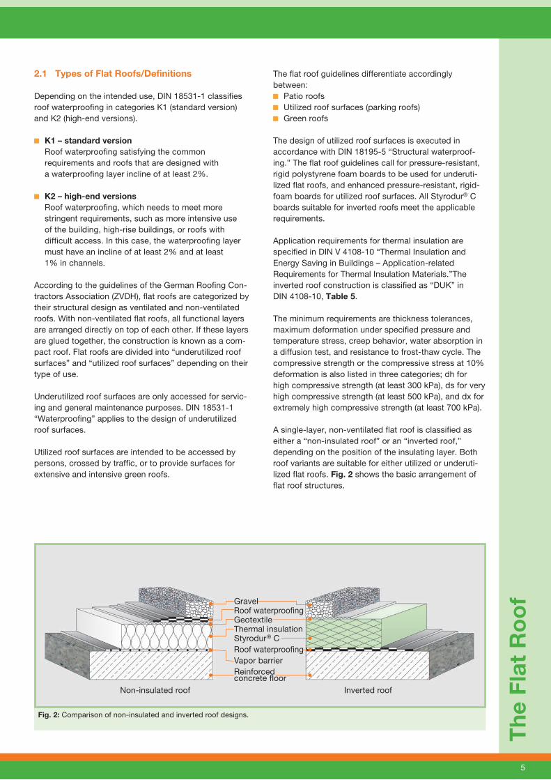
Gravel Roof waterproofingGeotextile Thermal insulationStyrodur® CRoof waterproofingVapor barrierReinforcedconcrete floor
Non-insulated roof Inverted roof
Fig. 2: Comparison of non-insulated and inverted roof designs.
5
Th
e F
lat
Ro
of
2.1 Types of Flat Roofs/Definitions
Depending on the intended use, DIN 18531-1 classifies roof waterproofing in categories K1 (standard version) and K2 (high-end versions).
K1 – standard version Roof waterproofing satisfying the common requirements and roofs that are designed with a waterproofing layer incline of at least 2%.
K2 – high-end versions Roof waterproofing, which needs to meet more stringent requirements, such as more intensive use of the building, high-rise buildings, or roofs with difficult access. In this case, the waterproofing layer must have an incline of at least 2% and at least 1% in channels.
According to the guidelines of the German Roofing Con-tractors Association (ZVDH), flat roofs are categorized by their structural design as ventilated and non-ventilated roofs. With non-ventilated flat roofs, all functional layers are arranged directly on top of each other. If these layers are glued together, the construction is known as a com-pact roof. Flat roofs are divided into “underutilized roof surfaces” and “utilized roof surfaces” depending on their type of use.
Underutilized roof surfaces are only accessed for servic-ing and general maintenance purposes. DIN 18531-1 “Waterproofing” applies to the design of underutilized roof surfaces.
Utilized roof surfaces are intended to be accessed by persons, crossed by traffic, or to provide surfaces for extensive and intensive green roofs.
The flat roof guidelines differentiate accordingly between:
Patio roofs Utilized roof surfaces (parking roofs) Green roofs
The design of utilized roof surfaces is executed in accordance with DIN 18195-5 “Structural waterproof-ing.” The flat roof guidelines call for pressure-resistant, rigid polystyrene foam boards to be used for underuti-lized flat roofs, and enhanced pressure-resistant, rigid-foam boards for utilized roof surfaces. All Styrodur® C boards suitable for inverted roofs meet the applicable requirements.
Application requirements for thermal insulation are specified in DIN V 4108-10 “Thermal Insulation and Energy Saving in Buildings – Application-related Requirements for Thermal Insulation Materials.”The inverted roof construction is classified as “DUK” in DIN 4108-10, Table 5.
The minimum requirements are thickness tolerances, maximum deformation under specified pressure and temperature stress, creep behavior, water absorption in a diffusion test, and resistance to frost-thaw cycle. The compressive strength or the compressive stress at 10% deformation is also listed in three categories; dh for high compressive strength (at least 300 kPa), ds for very high compressive strength (at least 500 kPa), and dx for extremely high compressive strength (at least 700 kPa).
A single-layer, non-ventilated flat roof is classified as either a “non-insulated roof” or an “inverted roof,” depending on the position of the insulating layer. Both roof variants are suitable for either utilized or underuti-lized flat roofs. Fig. 2 shows the basic arrangement of flat roof structures.

6
Th
e F
lat
Ro
of
A non-insulated roof is a single-layer, non-ventilated roof with weather-resistant waterproofing on top of the thermal insulation.
However, there are four different types of inverted roofs:
Single-layer inverted roof The most widely used “standard” inverted roof, in which the thermal insulating layer consists of extruded rigid polystyrene foam (XPS) arranged above waterproofing.
Double-layer inverted roof So far, individual approval was required for double- layer inverted roofs—and thus with increased energy efficiency. The German Institute for Building Techno logy (DIBt) has now approved the double-layer installation in gravel inverted roofs (Z-23.4.-222). Samplings and long-term studies of existing inverted roofs in Germany and Austria illustrate that Styrodur® C maintains its mechanical and physical properties over a very long period of time with virtually no variations.
Added DU for inverted roofs In calculating the thermal resistance coefficient (U value) of inverted roofs, the calculated U value is increased by the DU value. According to DIN 4108-2, this value is a function of the percentage of the thermal resistance below the sealing material of the total thermal resistance as given in Table 1. For substructures with an area-related mass of less than 250 kg/m², the thermal resistance below waterproofing must be at least 0.15 m² K/W.
According to approval Z-23.4-222, an added DU value is not required for inverted roof designs with a water-draining and vapor-permeable separation layer covered with gravel, above single or double Styrodur C boards.
Fig. 3: Inverted roof insulation with Styrodur® C for 250 housing units in Hamburg.
Table 1: Added values for inverted roofs (DIN 4108-2)
Room-side thermal resistance of waterproofing as a percentage of total thermal resistance %
Added value DU
W/(m²·K)
under 10 0,05
from 10 to 50 0,03
over 50 0
Duo Roof In the case of the so-called “duo roof,” an additional Styrodur C insulation layer is installed above waterproofing on top of a conventional non-insulated roof with XPS panels. With this design, which is used if installation of two-layer insulation according to approval is not possible, the vapor barrier can often be omitted, depending on weather conditions.
Plus Roof The “plus roof” is a design solution for roof renova- tion of flat roofs with insufficient thermal insulation. It is also used to combine the advantages of a non-insulated roof with those of an inverted roof. In order to protect the roof and extend its life span, an inverted roof with XPS is set on top of a non- insulated roof construction with, for example, EPS or mineral wool. In this case, a thermal insulation layer of Styrodur C is laid on top of the existing non- insulated roof construction. The existing roof waterproofing must be checked for proper function before proceeding.
The variants “single-layer inverted roof,”“duo roof,” and “plus roof” are suitable either for gravel, patio, green, or parking roofs. The inverted roof principle always remains the same, only the construction design is adapted. Inverted roof construction for gravel or patio roof designs are standardized in accordance with DIN 4108-2. The designs for green and parking roofs are regulated by the DIBt approval Z 23.4-222 (see download area of www.styrodur.de).
In accordance with the above-named national techni-cal approval, the “double-layer inverted roof” is only intended for use in gravel inverted roofs.

7
Ad
van
tag
es o
f th
e In
vert
ed R
oo
f S
yste
m
3. Advantages of the Inverted Roof System
An inverted roof consists of following layers (from top to bottom):
Functional or protective layer (e.g., gravel) Geotextile (polyester or polypropylene non-woven),
for single-layer insulation, the added DU value must be observed
Alternatively, water-draining and vapor-permeable separation layer in accordance with DIBt approval Z-23.4-222, the added DU value is not required
One or two layers of Styrodur® C insulation Roof waterproofing (and vapor barrier) If necessary, an inclined leveling course Roof structure, e.g., reinforced concrete floor
Note: Functional or protective layers, such as gravel, driving or terrace layers, green roofs, etc., also function as security against wind suction and provide protection against flying sparks or radiant heat.
The inverted roof is easier and faster to erect than the conventional non-insulated roof since it consists of less layers requiring laying and gluing.
With inverted roofs, the most important layer—water-proofing—lies on a solid, massive, and joint-free base, with the exception of plus roofs and duo roofs. If the sealing membrane is mechanically stressed then it can directly transfer the resulting loads. However, if an insulating layer is used as the substrate, small gaps between the individual insulating boards may form and waterproofing could “hang down” into these joints, which can lead to cracks.
If the roof waterproofing is glued over the expanse of the concrete ceiling, leaks can be easily located in the event of damage. Water appears on the inner side directly at the site where the roof waterproofing is dam-aged. This is not the case with conventional non-insu-lated roofs: if water trickles in through waterproofing, visible water damage often appears far from the location of the leak in the waterproofing layer.
In the case of non-insulated roofs, it is also important that no moisture is trapped between the vapor barrier and the waterproofing layer, which is often difficult to achieve in practice. When building a non-insulated roof, thermal insulation materials on site must be protected from moisture, and laid insulation boards must be covered.
As a rule, insulation boards may not be laid if it is rain-ing or foggy, otherwise the moisture trapped under the roof waterproofing will lead to vapor bubbles. In con-trast, the thermal insulation layer of inverted roofs can even be laid in the rain. Rainwater standing on the roof waterproofing can permeate through the Styrodur C thermal insulation layer or evaporate through the insulation board joints to the outside air. The waterproofing of inverted roofs should have a water vapor diffusion equivalent air layer thickness sd of at least 100 m. This significantly reduces the water vapor diffusion flow from the inside to the outside through the roof construction, and also prevents permeation of moisture into the interior of the building during the sum-mer months when the direction of diffusion is reversed.
As waterproofing in inverted roofs lies under the thermal insulation layer and the functional layers (e.g., gravel layer or covering), it is permanently protected from UV rays.
Depending on the further design of conventional non-insulated roofs, waterproofing may be directly exposed to the sun’s UV radiation, which can lead to damage of both bituminous and plastic waterproofing layers.
The temperature fluctuations of waterproofing are also significantly lower with inverted roofs. With conventional non-insulated roofs, the temperature fluctuation on the roof surface over the course of one year can reach up to 110 K. In contrast, the temperature fluctuation with inverted roofs over the course of a year is approximately 12 K if the temperature of the air in the room under the roof is 20°C.

8
Ad
van
tag
es o
f th
e In
vert
ed R
oo
f S
yste
m
Figures 4 and 5 show the daily thermal load in the waterproofing of a conventional non-insulated roof with and without gravel compared with that of an inverted roof. In non-insulated roofs, temperatures of water-proofing can peak at 90°C in summer, whereas the tem-perature remains almost constant when the waterproof-ing layer is protected by the thermal insulation layer, as is the case with inverted roofs. Thermal shocks, e.g., caused by hail storms in summer, don’t damage the waterproofing of inverted roofs.
The waterproofing of conventional non-insulated roofs is permanently exposed to mechanical strains. Often, damage already occurs during the construction phase due to work on the roof, storage of building materi-als, falling items, and many other reasons. By contrast, the inverted roof’s waterproofing is protected from mechanical damage thanks to the tough elastic thermal insulation layer. At the same time, the insulation acts as a protective layer in order to meet the requirements for waterproofing layers laid out in DIN 18195-10.
Fig. 6: Samples from a ten-year-old green inverted roof.
3.1 Advantages of Styrodur® C in Inverted Roofs
Styrodur® has been used in inverted roofs since the late 1970s and has been technically approved since 1978. Samples taken from working inverted roofs have demonstrated that Styrodur maintains its mechanical and physical properties over a very long period of time with virtually no variations (Fig. 5).
Fig. 4: Advantage of the inverted roof system: the insulation material on top of the roof waterproofing protects it from stronger temperature fluctuations, thermal shocks, mechanical damages, and the sun’s UV radiation.
Fig. 5: Thermal load of waterproofing in a non-insulated roof and an inverted roof.
Winter
Summer
0 12 0 12 0 12 0
80 60 40 20 0 -20
Time of the day
°C
Winter
Summer
0 12 0 12 0 12 0Time of the day
°C 80 60 40 20 0 -20
Winter
Summer
0 12 0 12 0 12 0Time of the day
°C 80 60 40 20 0 -20
Non-insulated roof without gravel Non-insulated roof with gravel Inverted roof
°C°C
Mechanical damage
UV
Non-insulated roof without gravel Non-insulated roof with gravel
Mechanical damage
UV
°C
Inverted roof
Mechanical damage
UV
°C
°C
9
Ad
van
tag
es o
f th
e In
vert
ed R
oo
f S
yste
m
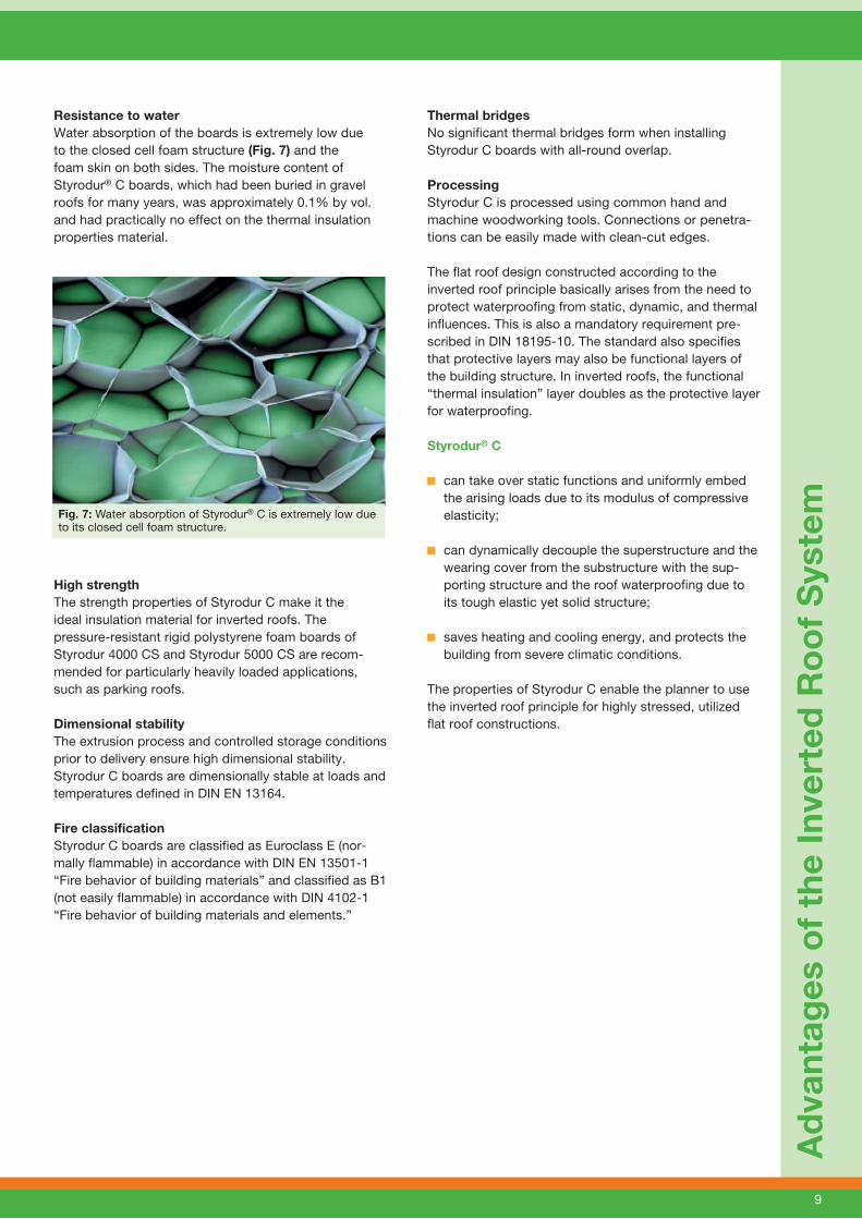
Resistance to water Water absorption of the boards is extremely low due to the closed cell foam structure (Fig. 7) and the foam skin on both sides. The moisture content of Styrodur® C boards, which had been buried in gravel roofs for many years, was approximately 0.1% by vol. and had practically no effect on the thermal insulation properties material.
High strengthThe strength properties of Styrodur C make it the ideal insulation material for inverted roofs. The pressure-resistant rigid polystyrene foam boards of Styrodur 4000 CS and Styrodur 5000 CS are recom-mended for particularly heavily loaded applications, such as parking roofs.
Dimensional stabilityThe extrusion process and controlled storage conditions prior to delivery ensure high dimensional stability. Styrodur C boards are dimensionally stable at loads and temperatures defined in DIN EN 13164. Fire classificationStyrodur C boards are classified as Euroclass E (nor-mally flammable) in accordance with DIN EN 13501-1 “Fire behavior of building materials” and classified as B1 (not easily flammable) in accordance with DIN 4102-1 “Fire behavior of building materials and elements.”
Thermal bridgesNo significant thermal bridges form when installing Styrodur C boards with all-round overlap.
ProcessingStyrodur C is processed using common hand and machine woodworking tools. Connections or penetra-tions can be easily made with clean-cut edges. The flat roof design constructed according to the inverted roof principle basically arises from the need to protect waterproofing from static, dynamic, and thermal influences. This is also a mandatory requirement pre-scribed in DIN 18195-10. The standard also specifies that protective layers may also be functional layers of the building structure. In inverted roofs, the functional “thermal insulation” layer doubles as the protective layer for waterproofing. Styrodur® C
can take over static functions and uniformly embed the arising loads due to its modulus of compressive elasticity;
can dynamically decouple the superstructure and the wearing cover from the substructure with the sup-porting structure and the roof waterproofing due to its tough elastic yet solid structure;
saves heating and cooling energy, and protects the building from severe climatic conditions.
The properties of Styrodur C enable the planner to use the inverted roof principle for highly stressed, utilized flat roof constructions.
Fig. 7: Water absorption of Styrodur® C is extremely low due to its closed cell foam structure.
10
4.1 Substructure
The inverted roof thermal insulation system can be implemented for single-layer (non-ventilated) flat roofs, for both heavy and light substructures provided that the following conditions are met:
Heavy substructures, such as solid ceilings, must have an area-related mass of 250 kg/m2. Light sub-structures, with an area-related mass less than 250 kg m2, must exhibit a thermal resistance of R ≥ 0.15 m2·K/W under waterproofing.
The high area-related mass and the prescribed minimum thermal resistance of the substructure are toprevent the underside of the ceiling from cooling so far that condensation forms, for instance during cold rain showers.
The surfaces upon which the roof waterproofing is to be laid must be clean and free of foreign objects. Concrete ceilings, including any sloping layers must be sufficiently hardened and their surface must be dry. The dimensional tolerances of DIN 18202 “Tolerances in building construction” and the valid “flat roof guidelines” must be complied with.
Inverted roofs with Styrodur® C do not require an incline. Although some water remains on the zero-degree surfaces after rain, this does not affect the functionality of inverted roofs, provided the insulating boards are not permanently flooded.
4.2 Roof Waterproofing
All common roof waterproofing materials are suitable for inverted roofs with an incline of more than two percent:
Bitumen roof sheeting Polymer-modified bitumen membranes Plastic sheeting High polymer sheeting
Inverted roofs with an incline of less than two percent are considered special constructions under the flat roof guideline and require special precautions to reduce risks associated with standing water. That is why, in the case of bituminous waterproofing under a top layer of polymer-bitumen membranes, either a further polymer-bitumen membrane or two layers of bitumen membranes are to be used. If the roof waterproofing consists of plastic sheeting then thicker membranes are to be used. Reference to the manufacturer’s processing specifications and the applicable flat roof guidelines is advisable.
Caution: Tar-based or solvent-based waterproofing is not suitable for inverted roofs with Styrodur C.
4.3 Roof Drainage
The drainage system of inverted roofs (see DIN EN 752, DIN EN 12056, and DIN 1986-10) is to be designed such that long-term flooding of the Styrodur® C boards is prevented. Short-term flooding during severe rain is harmless.
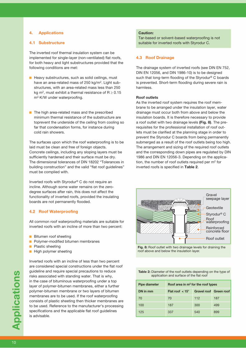
Roof outletsAs the inverted roof system requires the roof mem-brane to be arranged under the insulation layer, water drainage must occur both from above and below the insulation boards. It is therefore necessary to provide a roof outlet with two drainage levels (Fig. 8). The pre-requisites for the professional installation of roof out-lets must be clarified at the planning stage in order to prevent the Styrodur C boards from being permanently submerged as a result of the roof outlets being too high. The arrangement and sizing of the required roof outlets and the corresponding down pipes are regulated by DIN 1986 and DIN EN 12056-3. Depending on the applica-tion, the number of roof outlets required per m2 for inverted roofs is specified in Table 2.
Table 2: Diameter of the roof outlets depending on the type of application and surface of the flat roof
Pipe diameter Roof area in m2 for the roof types
DN in mm Flat roof < 15° Gravel roof Green roof
70 70 112 187
100 187 300 499
125 337 540 899
Ap
plic
atio
ns
Gravel seepage layer
Geotextile
Styrodur® CRoof waterproofing
Reinforced concrete floor Roof outlet
Fig. 8: Roof outlet with two drainage levels for draining the roof above and below the insulation layer.
4. Applications
11
Ap
plic
atio
ns
4.4 Thermal Insulation Layer
In order to avoid thermal bridges, inverted roof designs require Styrodur® C boards with overlap. The boards are joined in one or two layers, butted tightly with staggered transverse joints (avoid cross joints). In the case of parapet walls or rising brickwork with bituminous water-proofing, the Styrodur C boards are to be aligned with the insulation wedge as this enables the installation of the insulation material without forming thermal bridges. Because the insulating boards lie loosely on the roof waterproofing, they have no effect on each other in the event of thermal expansion.
Until now, inverted roofs have only been insulated with a single layer. BASF has demonstrated a secure double-layer application of Styrodur C based on the national technical approval Z-23.4-222 by the German Institute for Building Technology (DIBt).
As described in section 5.2, gravel inverted roofs with Styrodur C boards can now be laid as a double layer, provided that an approved compliant water-draining and vapor-permeable separation layer is placed between the Styrodur boards and the gravel layer.
„Isover AquaDefense UKD“ „Schwenk LiquiStopp LS“
In this case, the added DU value can be wavered (see page 6, Added DU values for inverted roofs, and download area of www.styrodur.de).
In special cases, the Styrodur C boards can be point glued to the waterproofing. For example, with bitu-minous waterproofing, this method can be used with blown bitumen B85/25 or cold bitumen adhesive.
The Styrodur C insulation layer is passable for persons and vehicles. For transport over the insulated surface, use wheelbarrows with suitable pneumatic tires. Styrodur C insulating boards are not resistant against substances containing solvents.
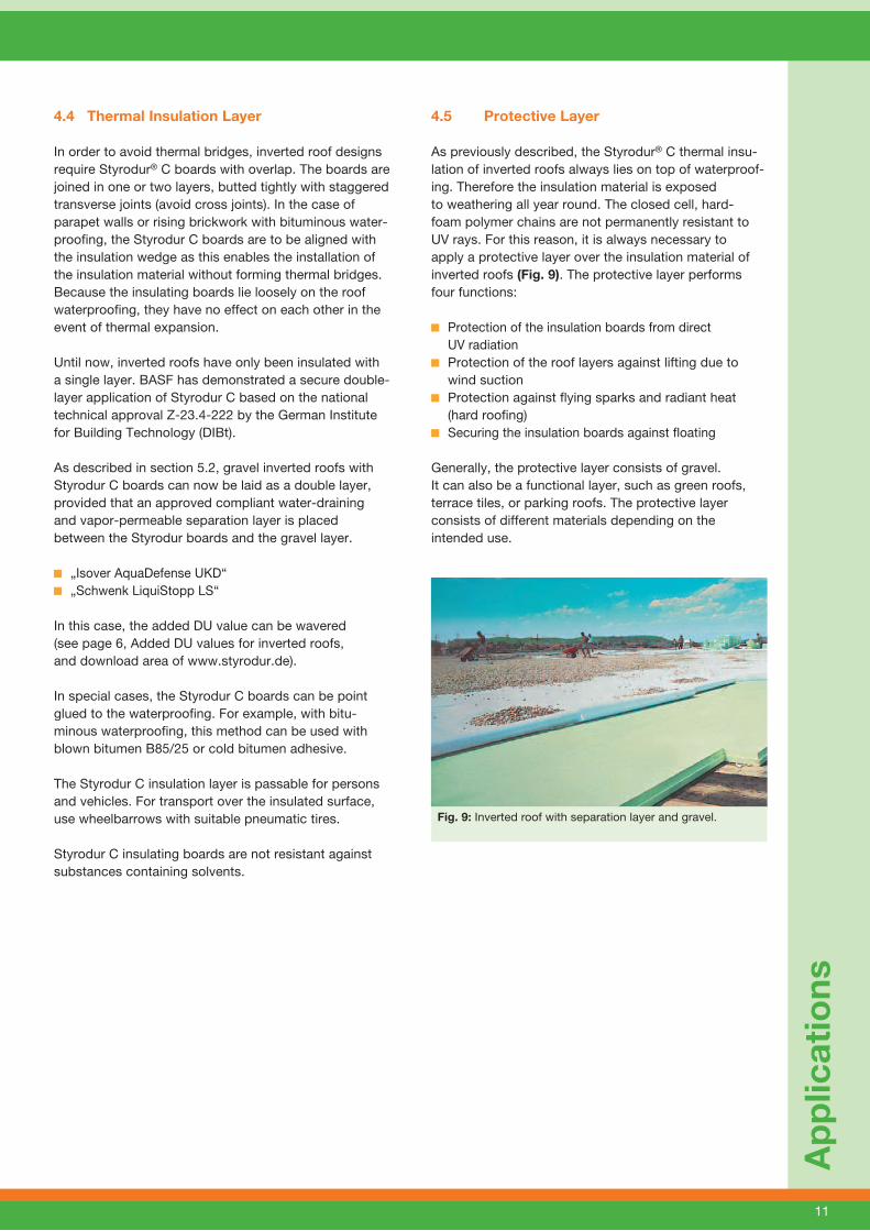
4.5 Protective Layer
As previously described, the Styrodur® C thermal insu-lation of inverted roofs always lies on top of waterproof-ing. Therefore the insulation material is exposed to weathering all year round. The closed cell, hard- foam polymer chains are not permanently resistant to UV rays. For this reason, it is always necessary to apply a protective layer over the insulation material of inverted roofs (Fig. 9). The protective layer performs four functions:
Protection of the insulation boards from direct UV radiation
Protection of the roof layers against lifting due to wind suction
Protection against flying sparks and radiant heat (hard roofing)
Securing the insulation boards against floating
Generally, the protective layer consists of gravel. It can also be a functional layer, such as green roofs, terrace tiles, or parking roofs. The protective layer consists of different materials depending on the intended use.
Fig. 9: Inverted roof with separation layer and gravel.
4 A
nw
end
un
gsh
inw
eise
12
4.6 Protection Against Floating
To prevent the insulation boards of inverted roofs from floating, a suitable load must be applied, e.g., a layer of gravel. A fill of washed, round gravel (Ø 16/32 mm) can be used to provide the necessary load and act as a protective layer at the same time. If required, the gravel can be coated with a sealer; however, it must not form a closed film over the Styrodur® C boards. The protective layer over the Styrodur C boards must be permanently vapor-permeable.
When used without a non-woven, and with a minimum thickness of 50 mm, the thickness of the gravel layer is always equal to the thickness of the insulation layer. If a non-woven is used, the gravel layer can be reduced to 50 mm (Table 3).
4.7 Protection Against Wind Suction
Protection of the Styrodur® C boards against wind suction is to be implemented in accordance with DIN 1055-4 or DIBt approval Z-23.4-222. The required load can be provided by a layer of gravel with a grain size of Ø 16/32 mm and a bulk density of ≥ 1,600 kg/m³ or using concrete slabs with a density of ≥ 2,000 kg/m³. The gravel layer must be secured against the effects of the wind.
Flat roofs and other roof types with an incline of up to 5° are subdivided into roof groups F to I (the groups A to E apply for vertical building structures such as walls; hipped roofs are subdivided into the groups F to N) in the wind load standard DIN 1055-4. In addition, the building height, location, and site (wind zone/wind pro-file) as well as the velocity pressures for buildings (kN/m²) are taken into account.
For the roof groups H and I (interior), the required load of approximately 0.75 kN/m² is to be met using a minimum gravel layer of 50 mm with a grain size of Ø 16/32 mm.
Buildings in geographically exposed locations, such as on mountain ridges or hillsides with extreme wind movements or with high buildings located in the vicinity, may require significantly higher loads.
In Appendix 1 to approval Z-23.4-222 by the DIBt, the following tables contain notes and values for securing against wind suction applicable to inverted roofs with a water-draining and vapor-permeable separation layer covered with gravel or with concrete slabs (see down-load area of www.styrodur.de).
Table 1: Maximum height of eave h above roof edge Table 2: Required load in kN/m² for securing against
wind suction for the roof groups F and G in accor- dance with DIN 1055-4, image 5
Table 3: Reduction factor K dependent on the width of edge and corner group F and G in accordance with DIN 1055-4, image 5
Table 4: Maximum building heights above ground at a sole load of gravel with a grain size of 16/32 for the roof groups F and G in accordance with DIN 1055-4, image 5
Table 5: Slab thickness t of concrete slabs in mm Table 6: Examples of loads on securing against
wind suction
Ap
plic
atio
ns
Table 3: Securing the Styrodur® C boards against floating
Thickness of insulation layer
Gravel layer
single-layerwithout
non-wovenwith non-woven
30-50 mm 50 mm 50 mm
60-200 mmequal to the
insulation layer thickness
50 mm
double-layerwater-draining, vapor-permeable
separation layer
220-400 mm 50 mm
13
5. Examples
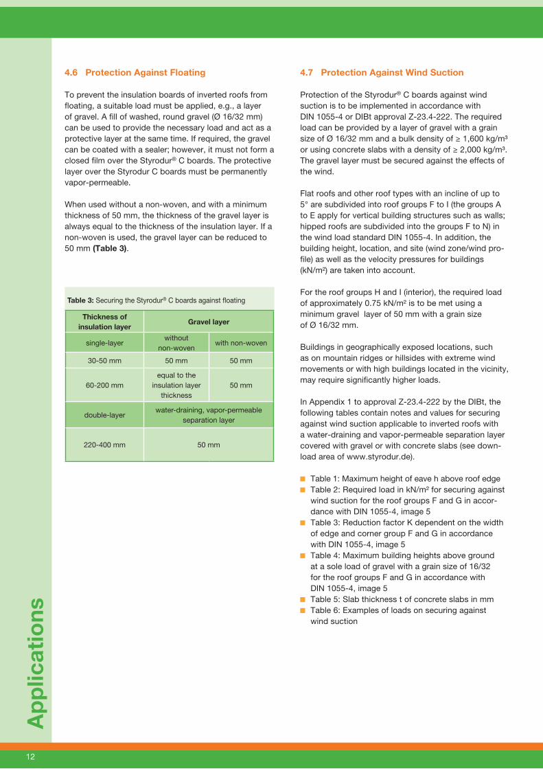
5.1 Inverted Gravel Roof – Single-layer
Depending on the requirements, Styrodur® C insulation boards 3035 CS, 4000 CS, or 5000 CS can be used for single-layer gravel inverted roofs. The following insulation thicknesses are possible in accordance with technical approval Z-23.4-222:
Styrodur 3035 CS min. 40 mm, max. 200 mm Styrodur 4000 CS min. 40 mm, max. 160 mm Styrodur 5000 CS min. 40 mm, max. 120 mm
The extruded foam boards must also have an all-round edge profiling, e.g., an overlap.
As trickle protection between the insulation layer and gravel protective layer, a polymer fleece resistant to decay and vapor-permeable with an area-related mass of approx. 140 g/m² protects the roof waterproofing from damage by fine, penetrating gravel particles (Fig. 10). A gravel layer prevents the individual Styrodur C boards from shifting and tilting caused by floating or wind suction. Plastic sealing membranes or PE films should under no circumstances be installed as a trickle protection because they act as a vapor barrier, whichwould cause the insulation layer to take in the water accumulating below.
After each rainfall, small amounts of water remain on the roof waterproofing, which must have a chance to evaporate at all times. It usually does so through the grooves of the Styrodur C boards by directly diffusing through the insulation material. This explains one of the fundamental rules of inverted roof systems: a vapor-permeable layer must always be installed on top of the insulation material. Roof surfaces exposed to regular access for maintenance work should be equipped with pavement flags.
Exa
mp
les
Fig. 10: Structure of a single-layer gravel inverted roof.
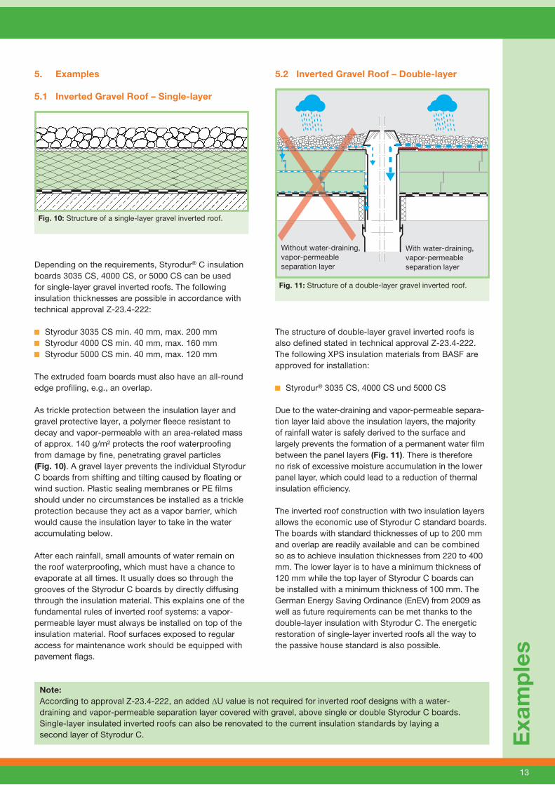
5.2 Inverted Gravel Roof – Double-layer
The structure of double-layer gravel inverted roofs is also defined stated in technical approval Z-23.4-222. The following XPS insulation materials from BASF are approved for installation:
Styrodur® 3035 CS, 4000 CS und 5000 CS
Due to the water-draining and vapor-permeable separa-tion layer laid above the insulation layers, the majority of rainfall water is safely derived to the surface and largely prevents the formation of a permanent water fi lm between the panel layers (Fig. 11). There is therefore no risk of excessive moisture accumulation in the lower panel layer, which could lead to a reduction of thermal insulation effi ciency.
The inverted roof construction with two insulation layers allows the economic use of Styrodur C standard boards. The boards with standard thicknesses of up to 200 mm and overlap are readily available and can be combined so as to achieve insulation thicknesses from 220 to 400 mm. The lower layer is to have a minimum thickness of 120 mm while the top layer of Styrodur C boards can be installed with a minimum thickness of 100 mm. The German Energy Saving Ordinance (EnEV) from 2009 as well as future requirements can be met thanks to the double-layer insulation with Styrodur C. The energetic restoration of single-layer inverted roofs all the way to the passive house standard is also possible.
Fig. 11: Structure of a double-layer gravel inverted roof.
Without water-draining, vapor-permeableseparation layer
With water-draining, vapor-permeable separation layer
Note: According to approval Z-23.4-222, an added DU value is not required for inverted roof designs with a water-draining and vapor-permeable separation layer covered with gravel, above single or double Styrodur C boards. Single-layer insulated inverted roofs can also be renovated to the current insulation standards by laying a second layer of Styrodur C.
14
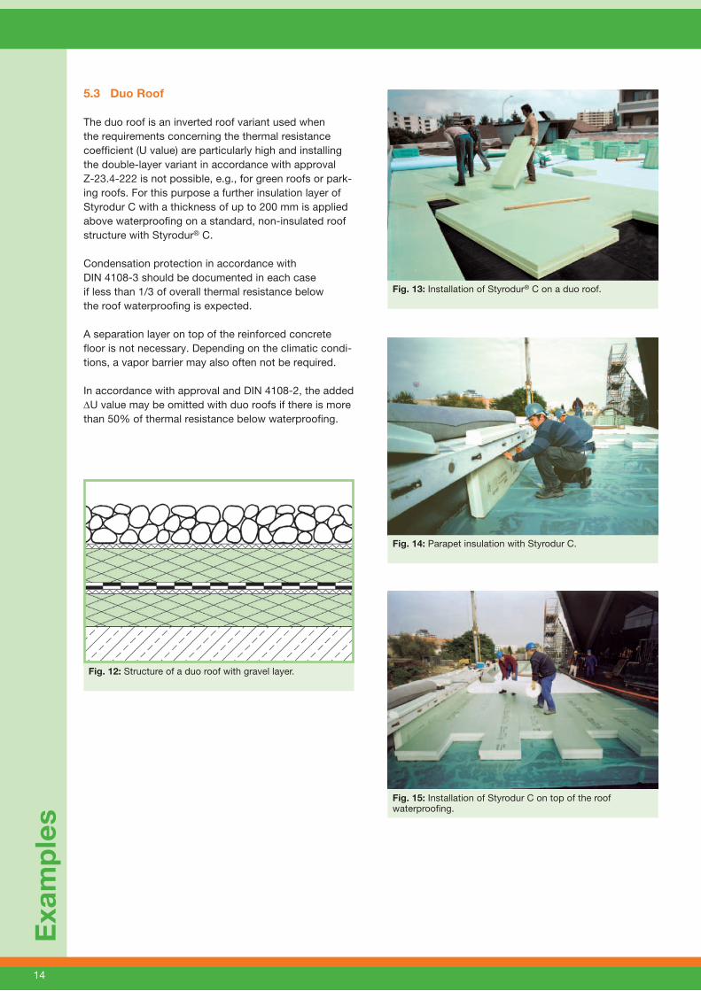
5.3 Duo Roof
The duo roof is an inverted roof variant used when the requirements concerning the thermal resistance coefficient (U value) are particularly high and installing the double-layer variant in accordance with approval Z-23.4-222 is not possible, e.g., for green roofs or park-ing roofs. For this purpose a further insulation layer of Styrodur C with a thickness of up to 200 mm is applied above waterproofing on a standard, non-insulated roof structure with Styrodur® C.
Condensation protection in accordance with DIN 4108-3 should be documented in each caseif less than 1/3 of overall thermal resistance below the roof waterproofing is expected.
A separation layer on top of the reinforced concrete floor is not necessary. Depending on the climatic condi-tions, a vapor barrier may also often not be required.
In accordance with approval and DIN 4108-2, the added DU value may be omitted with duo roofs if there is more than 50% of thermal resistance below waterproofing.
Exa
mp
les
Fig. 13: Installation of Styrodur® C on a duo roof.
Fig. 15: Installation of Styrodur C on top of the roof waterproofing.
Fig. 14: Parapet insulation with Styrodur C.
Fig. 12: Structure of a duo roof with gravel layer.

15
5.4 Plus Roof
The plus roof design is the perfect choice to reconstruct old, insufficiently insulated non-insulated roofs in order to meet today’s thermal insulation requirements (Fig. 16, left). The plus roof can be executed as single- or double-layer inverted roof to renovate an existing non-insulated roof if the conditions, such as incline, etc., comply with the approval principles.
The following steps are required in order to convert an existing non-insulated roof with gravel into a plus roof with Styrodur® C:
The existing layer of gravel is removed in sections and stored on the roof, taking into account the static requirements.
The existing roof waterproofing is to be examined for leakages and repaired, if necessary. Damages and faults are to be repaired professionally.
Connecting points to rising brickwork, skylights, ventilation plugs, and roof gutters are to be checked.
Connecting points to rising building elements must be minimum 15 cm above the top edge of the gravel layer and the finished plus roof. This level is reduced to at least 10 cm for roof gutters. When appropriate, connecting points should be increased (Fig. 18).
The Styrodur C boards are then installed and cove red with geotextile. According to DIBt approval Z-23.4-222 for double-layer gravel installation, a water-draining, vapor-permeable separation layer must be arranged on top of the Styrodur C boards.
Exa
mp
les
Fig. 18: Gravel roof.
Fig. 17: Renovated inverted roof in the form of a plus roof.
Fig. 16: Left: new plus roof; right: old non-insulated roof.
The temporarily stored gravel can be distributed on the insulation layer in sections (Fig. 17) until the energetic restoration of the entire roof surface has been completed.
If the substructure provides the necessary load-bearing capacity, refurbished non-insulated roofs may also be converted into green inverted roofs. The existing roof waterproofing is to be examined for its resistance to roots. If necessary, an additional root-barrier membrane is to be applied.

Fig. 19: Structure of a green roof.
16
5.5 Green Roof
Extensive or intensive green roofs with water features, paths, and plazas can be created on any functional inverted roof construction (Fig. 19). The substructure is to be checked for static load-bearing capacity. A vapor-permeable layer must be installed on top of the thermal insulation layer of Styrodur® C boards. The notes in the national technical approval Z-23.4-222 are to be com-plied with (download area of www.styrodur.de).
The green inverted roof design holds many advantages compared with the non-insulated roof:
The thermal insulation protects the root-resistant waterproofing from thermal stresses (Fig. 20).
During the construction phase, the insulation package provides reliable protection against mechanical strains.
Exa
mp
les
Fig. 21: Stress on a green roof.
Once the green roof is in use, the insulation layer
protects the underlying waterproofing against rakes or other garden appliances used for maintenance (Fig. 21).
During the construction period of inverted green roofs, there is a clear separation between the trades. The roofer takes care of waterproofing and thermal insulation while the roof gardener is responsible for the substrate layer and greening. This simplifies the approval and the guarantee.
Often companies offer green roofs as a complete system.
On inverted roofs, insulation materials made of extruded foam may not be permanently flooded with rainwater. To meet the structural-physical principle of inverted roofs, a vapor-permeable layer is to be applied between the water storage level and the Styrodur C boards. This may consist of Styropor compact boards, for example (Fig. 22).
0 °C + 10 °C
– 10 °C Outside air temperature + 35 °C
+ 20 °CInterior temperature + 20 °C
+ 30 °C
Substrate
Filter fleece
Seepage layer
Geotextile
Styrodur® C
Root-barrier membrane
Roof waterproofing
Reinforced concrete floor
Fig. 20: Temperature profile in an inverted green roof.
– 10 °C
17
Exa
mp
les
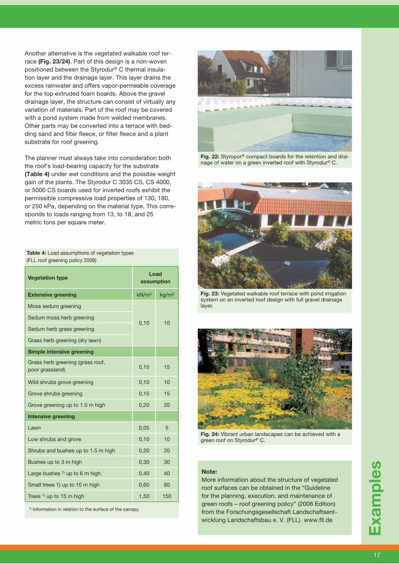
Fig. 23: Vegetated walkable roof terrace with pond irrigation system on an inverted roof design with full gravel drainage layer.
Fig. 22: Styropor® compact boards for the retention and drai-nage of water on a green inverted roof with Styrodur® C.
Fig. 24: Vibrant urban landscapes can be achieved with a green roof on Styrodur® C.
Another alternative is the vegetated walkable roof ter-race (Fig. 23/24). Part of this design is a non-woven positioned between the Styrodur® C thermal insula-tion layer and the drainage layer. This layer drains the excess rainwater and offers vapor-permeable coverage for the top extruded foam boards. Above the gravel drainage layer, the structure can consist of virtually any variation of materials. Part of the roof may be covered with a pond system made from welded membranes. Other parts may be converted into a terrace with bed-ding sand and filter fleece, or filter fleece and a plant substrate for roof greening.
The planner must always take into consideration both the roof’s load-bearing capacity for the substrate (Table 4) under wet conditions and the possible weight gain of the plants. The Styrodur C 3035 CS, CS 4000, or 5000 CS boards used for inverted roofs exhibit the permissible compressive load properties of 130, 180, or 250 kPa, depending on the material type. This corre-sponds to loads ranging from 13, to 18, and 25 metric tons per square meter.
Table 4: Load assumptions of vegetation types (FLL roof greening policy 2008)
Vegetation type Load
assumption
Extensive greening kN/m² kg/m²
Moss sedum greening
0,10 10Sedum moss herb greening
Sedum herb grass greening
Grass herb greening (dry lawn)
Simple intensive greening
Grass herb greening (grass roof, poor grassland) 0,15 15
Wild shrubs grove greening 0,10 10
Grove shrubs greening 0,15 15
Grove greening up to 1.5 m high 0,20 20
Intensive greening
Lawn 0,05 5
Low shrubs and grove 0,10 10
Shrubs and bushes up to 1.5 m high 0,20 20
Bushes up to 3 m high 0,30 30
Large bushes 1) up to 6 m high 0,40 40
Small trees 1) up to 10 m high 0,60 60
Trees 1) up to 15 m high 1,50 150
1) Information in relation to the surface of the canopy.
Note:More information about the structure of vegetated roof surfaces can be obtained in the “Guideline for the planning, execution, and maintenance of green roofs – roof greening policy” (2008 Edition) from the Forschungsgesellschaft Landschaftsent-wicklung Landschaftsbau e. V. (FLL). www.fll.de
18
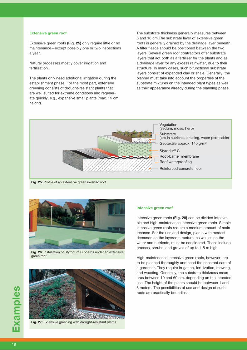
Extensive green roof
Extensive green roofs (Fig. 25) only require little or no maintenance—except possibly one or two inspections a year.
Natural processes mostly cover irrigation and fertilization.
The plants only need additional irrigation during the establishment phase. For the most part, extensive greening consists of drought-resistant plants that are well suited for extreme conditions and regener-ate quickly, e.g., expansive small plants (max. 15 cm height).
The substrate thickness generally measures between 6 and 16 cm.The substrate layer of extensive green roofs is generally drained by the drainage layer beneath. A filter fleece should be positioned between the two layers. Several green roof contractors offer substrate layers that act both as a fertilizer for the plants and as a drainage layer for any excess rainwater, due to their structure. In many cases, such bifunctional substrate layers consist of expanded clay or shale. Generally, the planner must take into account the properties of the substrate mixtures on the intended plant types as well as their appearance already during the planning phase.
Intensive green roof
Intensive green roofs (Fig. 28) can be divided into sim-ple and high-maintenance intensive green roofs. Simple intensive green roofs require a medium amount of main-tenance. For the use and design, plants with modest demands on the layered structure, as well as on the water and nutrients, must be considered. These include grasses, shrubs, and groves of up to 1.5 m high.
High-maintenance intensive green roofs, however, are to be planned thoroughly and need the constant care of a gardener. They require irrigation, fertilization, mowing, and weeding. Generally, the substrate thickness meas-ures between 10 and 60 cm, depending on the intended use. The height of the plants should be between 1 and 3 meters. The possibilities of use and design of such roofs are practically boundless.
Exa
mp
les
Vegetation (sedum, moss, herb)
Substrate (low in nutrients, draining, vapor-permeable)
Geotextile approx. 140 g/m2
Styrodur® C
Root-barrier membrane
Roof waterproofi ng
Reinforced concrete fl oor
Fig. 25: Profile of an extensive green inverted roof.
Fig. 26: Installation of Styrodur® C boards under an extensive green roof.
Fig. 27: Extensive greening with drought-resistant plants.
19
Most suitable are plants used for extensive and simple intensive green roofs, ornamental lawns, high-mainte-nance bushes between 3 and 6 meters height, as well as small and tall trees. In order to permanently maintain green inverted roofs—with either extensive or intensive greening—certain aspects must be taken into account for each functional layer.
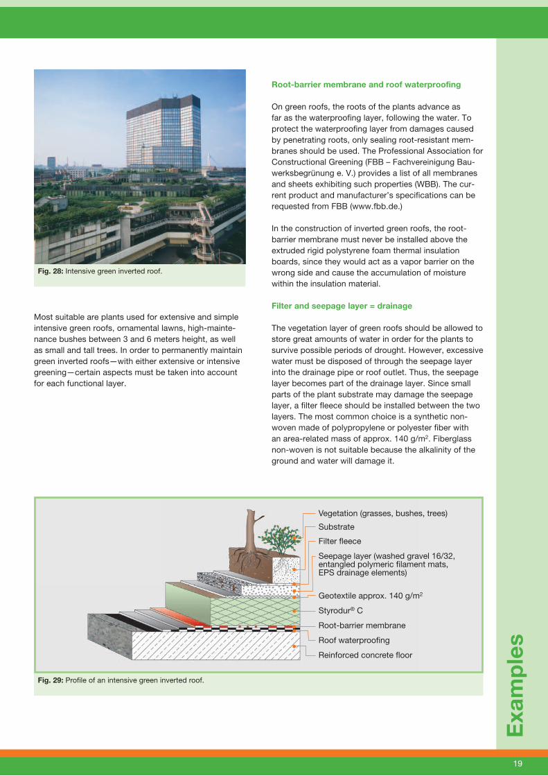
Root-barrier membrane and roof waterproofing
On green roofs, the roots of the plants advance as far as the waterproofing layer, following the water. To protect the waterproofing layer from damages caused by penetrating roots, only sealing root-resistant mem-branes should be used. The Professional Association for Constructional Greening (FBB – Fachvereinigung Bau-werksbegrünung e. V.) provides a list of all membranes and sheets exhibiting such properties (WBB). The cur-rent product and manufacturer’s specifications can be requested from FBB (www.fbb.de.)
In the construction of inverted green roofs, the root-barrier membrane must never be installed above the extruded rigid polystyrene foam thermal insulation boards, since they would act as a vapor barrier on the wrong side and cause the accumulation of moisture within the insulation material.
Filter and seepage layer = drainage
The vegetation layer of green roofs should be allowed to store great amounts of water in order for the plants to survive possible periods of drought. However, excessive water must be disposed of through the seepage layer into the drainage pipe or roof outlet. Thus, the seepage layer becomes part of the drainage layer. Since small parts of the plant substrate may damage the seepage layer, a filter fleece should be installed between the two layers. The most common choice is a synthetic non-woven made of polypropylene or polyester fiber with an area-related mass of approx. 140 g/m2. Fiberglass non-woven is not suitable because the alkalinity of the ground and water will damage it.
Exa
mp
les
Fig. 28: Intensive green inverted roof.
Vegetation (grasses, bushes, trees)
Substrate
Filter fl eece
Seepage layer (washed gravel 16/32, entangled polymeric fi lament mats, EPS drainage elements)
Geotextile approx. 140 g/m2
Styrodur® C
Root-barrier membrane
Roof waterproofi ng
Reinforced concrete fl oor
Fig. 29: Profile of an intensive green inverted roof.

20
Functions of the seepage layer in inverted roofs
The drainage layer absorbs excess water, which cannot be retained by the vegetation layer, and leads it along the roof incline to a drainage pipe or roof outlet (Fig. 30).
The seepage layer of inverted roofs must not only drain rainwater but also the guarantee the vapor permeability of the insulation material. The water vapor must diffuse through the thermal insulation layer and pass through the seepage layer where is condenses. Under certain climatic conditions, this condensate present in the lay-ers of green roofs can benefit the substrate layer and in turn the plants. If the substrate is saturated and cannot retain any more water, the condensate flows toward the roof outlet or settles on the waterproofing. From there, it enters the diffusion cycle once more.
The drainage layer must be able to bear the load caused by the weight of the substrate, various other constructions, as well as the traffic load, as in the case of walkable green roofs. It should be as light as possible in order to protect the substructure from unnecessary strain. In addition, it must be frost- and rot-proof. The following materials are suitable as seepage layers:
Seepage layer made of concrete drainage stones
Concrete drainage stones are only suitable for thick plant substrate layers. In general, they are not as suita-ble for roof greening because they may cause structural damages. The constant fall of water washes the lime out of the concrete drainage stone, which may settle as lime hydrate inside the roof outlets and down pipes, which can lead to sintering and even complete clogging of the outlets.
Seepage layer made of granular materials(e.g., gravel, expanded clay, or lava)
Particularly in the case of extensive greening with very thin substrate layers, gravel seepage layers are often the only choice to reach the mandatory load of 100 kg/m2. By contrast, for intensive greening with very thick substrate layers, seepage layers made of expanded clay or lava are more suitable due to their comparably light weight.
Seepage layers made of foam plastics, e.g., EPS drain-age boards or entangled polymeric filament mats (e.g., from polypropylene) are especially light. Recycled prod-ucts, such as foam mats and plastic shavings are also suitable.
Technically speaking, these seepage layers can also be considered drainage layers. The entangled polymeric filament mat has a tight non-woven on both surfaces, which makes it a drainage element in the form of a mat. EPS drainage boards usually do not need a non-woven layer because their foam structure is already tight. Thereby, they already meet the requirements for both seepage and filter layers.
When using plastic drainage elements, it should be noted that the constant strain from the vegetation layer as well as the traffic load may cause a reduction or deformation of the material. When using deformable drainage elements, the assumed thickness of the ele-ments after fifty years must be taken into account to ensure lasting water drainage. For example, at a load of 10 kN/m2, only 60–80% of the original pipe cross-section is generally to be calculated (Fig. 31). Manufac-turers provide the relevant information for prefabricated drainage elements.
Exa
mp
les
Substrate
Filter fl eece
Seepage layer Geotextile approx. 140 g/m2
Styrodur® C
Root-barrier membrane
Roof waterproofi ngReinforced concrete fl oor
Fig. 30: Structure of a green inverted roof with drainage layer for surface water absorption and, alternatively, drainage pipe.
Fig. 31: Thickness change as a function of the load.
Concrete fi lter stonesGrated matsSlotted PS drainage board
EPS drainage boardsEntangled polymeric fi lament mats
Thickness (%)100
80
60
40
20
00 10 20 30 40 50 Load (kN/m2)
21
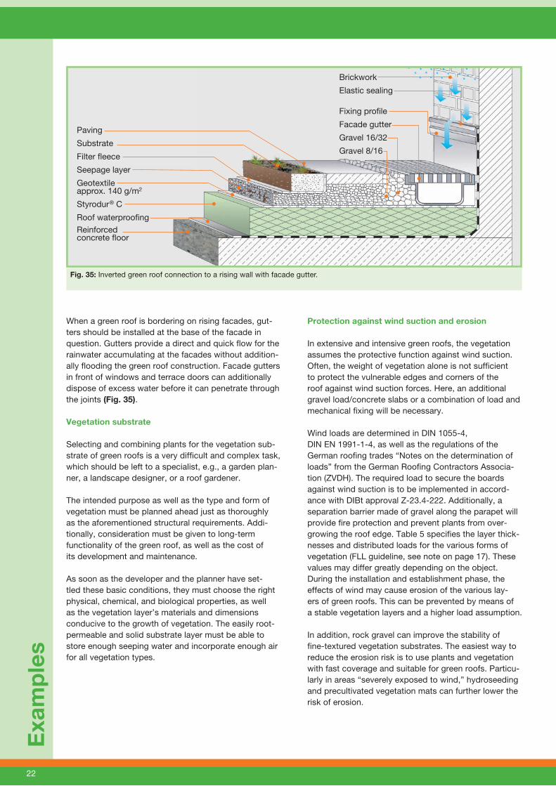
Fig. 34: Roof outlet with inspection shaft of an intensive inverted green roof and expanded clay seepage layer.
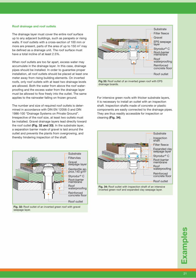
Roof drainage and roof outlets
The drainage layer must cover the entire roof surface up to any adjacent buildings, such as parapets or rising walls. If roof outlets with a cross-section of 100 mm or more are present, parts of the area of up to 150 m2 may be defined as a drainage unit. The roof surface must have a total incline of at least 2.5%.
When roof outlets are too far apart, excess water may accumulate in the drainage layer. In this case, drainage pipes should be installed. In order to guarantee proper installation, all roof outlets should be placed at least one meter away from rising building elements. On inverted roofs, only roof outlets with at least two drainage levels are allowed. Both the water from above the roof water-proofing and the excess water from the drainage layer must be allowed to flow freely into the outlet. The same applies to the rainwater falling on frozen ground.
The number and size of required roof outlets is deter-mined in accordance with DIN EN 12056-3 and DIN 1986-100 “Drainage Systems on Private Ground”.Irrespective of the roof size, at least two outlets must be installed. Gravel drainage layers lead directly toward the roof outlet (Fig. 32 and 33). In the substrate layer, a separation barrier made of gravel is laid around the outlet and prevents the plants from overgrowing, and thereby hindering inspection of the shaft.
For intensive green roofs with thicker substrate layers, it is necessary to install an outlet with an inspection shaft. Inspection shafts made of concrete or plastic components are easily connected to the drainage pipes. They are thus readily accessible for inspection or cleaning (Fig. 34).
Exa
mp
les
Fig. 32: Roof outlet of an inverted green roof with gravel seepage layer.
SubstrateFiltervliesGravel seepage layer Geotextile ap-prox.140 g/m2 Styrodur® CRoot-barrier membrane Roof waterproofi ng
Reinforced concrete fl oor
Roof outlet
SubstrateFilter fl eece GravelEPS seepage layer
Styrodur® CRoot-barrier membrane
Roof waterproofi ngReinforced concrete fl oor Roof outlet
Fig 33: Roof outlet of an inverted green roof with EPS drainage boards.
Substrate
Inspection shaftFilter fl eece Expanded clay seepage layer
Styrodur® CRoot-barrier membrane Roof waterproofi ng
Reinforced concrete fl oor Roof outlet
22
Fig. 35: Inverted green roof connection to a rising wall with facade gutter.
Protection against wind suction and erosion
In extensive and intensive green roofs, the vegetation assumes the protective function against wind suction. Often, the weight of vegetation alone is not sufficient to protect the vulnerable edges and corners of the roof against wind suction forces. Here, an additional gravel load/concrete slabs or a combination of load and mechanical fixing will be necessary. Wind loads are determined in DIN 1055-4, DIN EN 1991-1-4, as well as the regulations of the German roofing trades “Notes on the determination of loads” from the German Roofing Contractors Associa-tion (ZVDH). The required load to secure the boards against wind suction is to be implemented in accord-ance with DIBt approval Z-23.4-222. Additionally, a separation barrier made of gravel along the parapet will provide fire protection and prevent plants from over-growing the roof edge. Table 5 specifies the layer thick-nesses and distributed loads for the various forms of vegetation (FLL guideline, see note on page 17). These values may differ greatly depending on the object. During the installation and establishment phase, the effects of wind may cause erosion of the various lay-ers of green roofs. This can be prevented by means of a stable vegetation layers and a higher load assumption.
In addition, rock gravel can improve the stability of fine-textured vegetation substrates. The easiest way to reduce the erosion risk is to use plants and vegetation with fast coverage and suitable for green roofs. Particu-larly in areas “severely exposed to wind,” hydroseeding and precultivated vegetation mats can further lower the risk of erosion.
When a green roof is bordering on rising facades, gut-ters should be installed at the base of the facade in question. Gutters provide a direct and quick flow for the rainwater accumulating at the facades without addition-ally flooding the green roof construction. Facade gutters in front of windows and terrace doors can additionally dispose of excess water before it can penetrate through the joints (Fig. 35).
Vegetation substrate
Selecting and combining plants for the vegetation sub-strate of green roofs is a very difficult and complex task, which should be left to a specialist, e.g., a garden plan-ner, a landscape designer, or a roof gardener.
The intended purpose as well as the type and form of vegetation must be planned ahead just as thoroughly as the aforementioned structural requirements. Addi-tionally, consideration must be given to long-term functionality of the green roof, as well as the cost of its development and maintenance.
As soon as the developer and the planner have set-tled these basic conditions, they must choose the right physical, chemical, and biological properties, as well as the vegetation layer’s materials and dimensions conducive to the growth of vegetation. The easily root-permeable and solid substrate layer must be able to store enough seeping water and incorporate enough air for all vegetation types.
Exa
mp
les
Paving
Substrate
Filter fl eece
Seepage layer
Geotextile approx. 140 g/m2
Styrodur® C
Roof waterproofi ng
Reinforced concrete fl oor
Brickwork
Elastic sealing
Fixing profi le
Facade gutter
Gravel 16/32
Gravel 8/16
23
Exa
mp
les
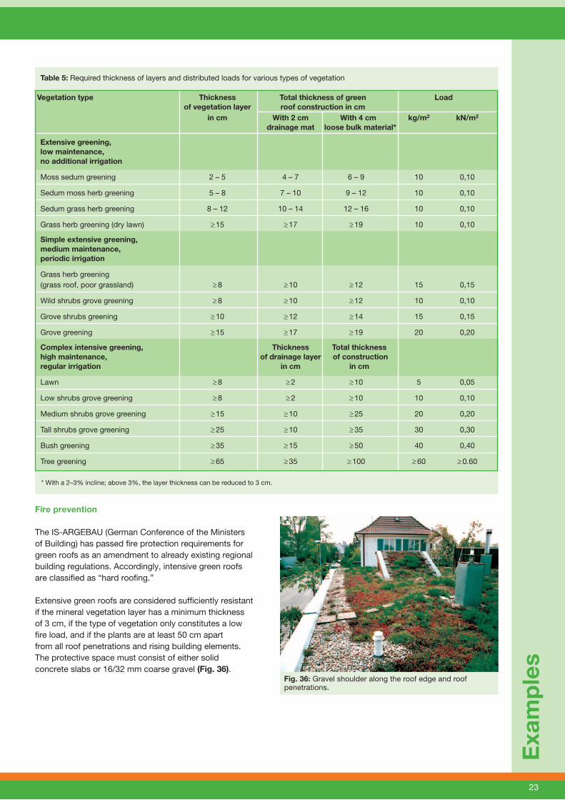
* With a 2–3% incline; above 3%, the layer thickness can be reduced to 3 cm.
Fire prevention
The IS-ARGEBAU (German Conference of the Ministers of Building) has passed fire protection requirements for green roofs as an amendment to already existing regional building regulations. Accordingly, intensive green roofs are classified as “hard roofing.”
Extensive green roofs are considered sufficiently resistant if the mineral vegetation layer has a minimum thickness of 3 cm, if the type of vegetation only constitutes a low fire load, and if the plants are at least 50 cm apart from all roof penetrations and rising building elements. The protective space must consist of either solid concrete slabs or 16/32 mm coarse gravel (Fig. 36).
Fig. 36: Gravel shoulder along the roof edge and roof penetrations.
Table 5: Required thickness of layers and distributed loads for various types of vegetation
Vegetation type Thickness Total thickness of green Load of vegetation layer roof construction in cm in cm With 2 cm With 4 cm kg/m2 kN/m2 drainage mat loose bulk material*
Extensive greening, low maintenance, no additional irrigation
Moss sedum greening 2 – 5 4 – 7 6 – 9 10 0,10
Sedum moss herb greening 5 – 8 7 – 10 9 – 12 10 0,10
Sedum grass herb greening 8 – 12 10 – 14 12 – 16 10 0,10
Grass herb greening (dry lawn) ≥ 15 ≥ 17 ≥ 19 10 0,10
Simple extensive greening, medium maintenance, periodic irrigation
Grass herb greening (grass roof, poor grassland) ≥ 8 ≥ 10 ≥ 12 15 0,15
Wild shrubs grove greening ≥ 8 ≥ 10 ≥ 12 10 0,10
Grove shrubs greening ≥ 10 ≥ 12 ≥ 14 15 0,15
Grove greening ≥ 15 ≥ 17 ≥ 19 20 0,20
Complex intensive greening, Thickness Total thickness high maintenance, of drainage layer of construction regular irrigation in cm in cm
Lawn ≥ 8 ≥ 2 ≥ 10 5 0,05
Low shrubs grove greening ≥ 8 ≥ 2 ≥ 10 10 0,10
Medium shrubs grove greening ≥ 15 ≥ 10 ≥ 25 20 0,20
Tall shrubs grove greening ≥ 25 ≥ 10 ≥ 35 30 0,30
Bush greening ≥ 35 ≥ 15 ≥ 50 40 0,40
Tree greening ≥ 65 ≥ 35 ≥ 100 ≥ 60 ≥ 0.60
24
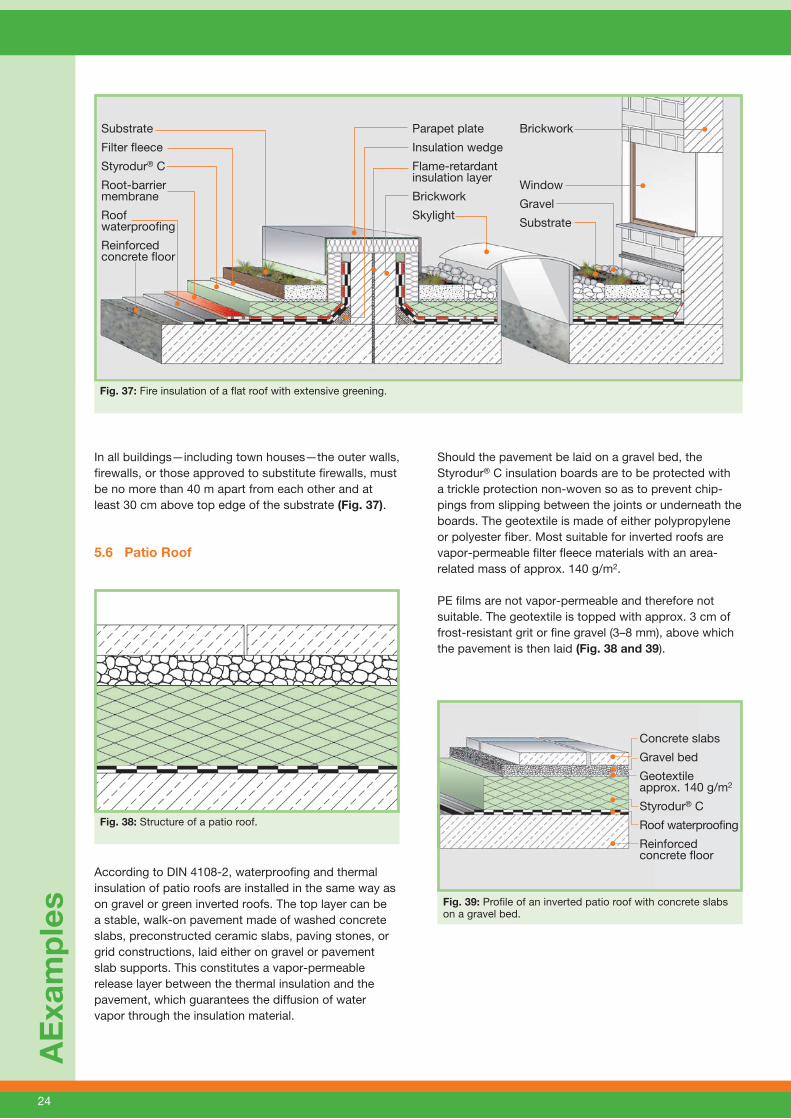
5.6 Patio Roof
According to DIN 4108-2, waterproofing and thermal insulation of patio roofs are installed in the same way as on gravel or green inverted roofs. The top layer can be a stable, walk-on pavement made of washed concrete slabs, preconstructed ceramic slabs, paving stones, or grid constructions, laid either on gravel or pavement slab supports. This constitutes a vapor-permeable release layer between the thermal insulation and the pavement, which guarantees the diffusion of water vapor through the insulation material.
Should the pavement be laid on a gravel bed, the Styrodur® C insulation boards are to be protected with a trickle protection non-woven so as to prevent chip-pings from slipping between the joints or underneath the boards. The geotextile is made of either polypropylene or polyester fiber. Most suitable for inverted roofs are vapor-permeable filter fleece materials with an area-related mass of approx. 140 g/m2.
PE films are not vapor-permeable and therefore not suitable. The geotextile is topped with approx. 3 cm of frost-resistant grit or fine gravel (3–8 mm), above which the pavement is then laid (Fig. 38 and 39).
AE
xam
ple
s
Fig. 37: Fire insulation of a flat roof with extensive greening.
Fig. 38: Structure of a patio roof.
In all buildings—including town houses—the outer walls, firewalls, or those approved to substitute firewalls, must be no more than 40 m apart from each other and at least 30 cm above top edge of the substrate (Fig. 37).
Concrete slabs
Gravel bed
Geotextile approx. 140 g/m2
Styrodur® C
Roof waterproofi ng
Reinforced concrete fl oor
Fig. 39: Profile of an inverted patio roof with concrete slabs on a gravel bed.
Substrate
Filter fl eece
Styrodur® C
Root-barrier membrane
Roof waterproofi ng
Reinforced concrete fl oor
Parapet plate
Insulation wedge
Flame-retardant insulation layer
Brickwork
Skylight
Brickwork
Window
Gravel
Substrate

25
5.7 Parking Roof
The roofs of public buildings, department stores, and warehouses are increasingly used as parking roofs. To minimize the heat loss from the heated areas below parking roofs, these are insulated with Styrodur® C boards following the principle of inverted roof construc-tions (Fig. 40). In accordance with the general technical approval Z-23.4-222 (download area of www.styrodur.de), the following design variants are possible:
Prefabricated concrete slabs on pavement slab supports
Composite stone pavement laid on gravelt In-situ concrete slabs laid on incline
Due to their high compressive strength, Styrodur C boards can handle the strain of parking and moving cars if the following building guidelines are applied.
Fig. 41 left shows the structure of a conventional park-ing roof with thermal insulation. In this design, the roof membrane near the concrete slab joints can very easily be damaged due to the dynamic load of the moving wheels. In an inverted roof construction (Fig. 41 right), waterproofing is protected from such dynamic loads by the thermal insulation layer.
A second possible layout is the use of pavement slab supports (Fig. 43) made of aging- and weathering-resistant plastic. The pavement slab supports are located at the intersection of the slab joints. Spacers ensure regular joint design. Water is guided underneath the paving onto the insulation material.
The surface water flowing through the open joints leads to some self-cleaning between the thermal insulation boards and the pavement. Nevertheless, at least once a year, a few of the pavement slabs should be lifted and the spaces between them should be cleared of any accumulated dirt with a pressure hose.
Exa
mp
les
Variant 1a: large-size concrete slabs on pavement slab supports
Reinforced prefabricated concrete slabs (1,500 x 2,000 x 80 mm) are laid on top of the Styrodur C boards, which are covered with vapor-permeable polymer fleece. However, the boards are approx. 100 mm thick at the edges. This leads to a void of 20 mm between the concrete slabs and the thermal insulation boards, which enables the atmospheric moisture to diffuse (Fig. 42). In order to keep the reinforced concrete slabs from shifting under the traffic load, the edges are to be fitted with rubber buffers that distribute the horizontal forces between the slabs.
Because the weight of parking cars is only transmitted onto the insulation boards via the edges of the concrete slabs (point load), it is necessary to lay Styrodur 5000 CS boards with high compressive strength. Since leve-ling is not possible when installing such large-size slabs, it is crucial that the planner and builder ensure that the reinforced concrete floor—including waterproofing—does not show any swelling and the insulation boards are laid on a fully even surface.
Fig. 40: Structure of a parking roof.
Reinforced concrete slabsAir layerGeotextile approx. 140 g/m2
Styrodur® CRoof waterproofi ngReinforced concrete fl oor
Fig. 42: Parking roof with large-size reinforced concrete slabs on pavement slab supports.
The waterproofing of non-isulated roofs is under particular stress at the joints of the driving surface.
By contrast, the insulation layer on top protects the waterproo-fing of inverted roofs.
Fig. 41: Parking roof in the form of a conventional non-insu-lated roof and as an inverted roof. While the waterproofing of the non-insulated roof design could be damaged, it lies safely protected in the inverted roof design.
26
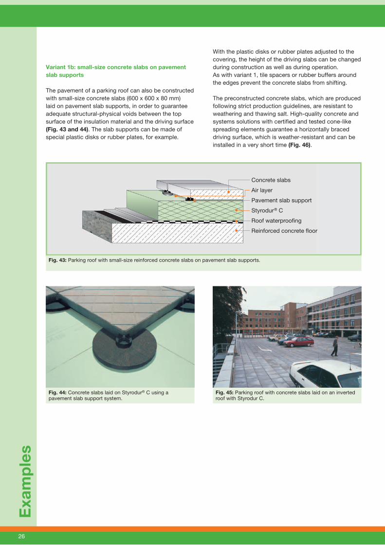
Variant 1b: small-size concrete slabs on pavement slab supports
The pavement of a parking roof can also be constructed with small-size concrete slabs (600 x 600 x 80 mm) laid on pavement slab supports, in order to guarantee adequate structural-physical voids between the top surface of the insulation material and the driving surface (Fig. 43 and 44). The slab supports can be made of special plastic disks or rubber plates, for example.
Exa
mp
les
With the plastic disks or rubber plates adjusted to the covering, the height of the driving slabs can be changed during construction as well as during operation. As with variant 1, tile spacers or rubber buffers around the edges prevent the concrete slabs from shifting.
The preconstructed concrete slabs, which are produced following strict production guidelines, are resistant to weathering and thawing salt. High-quality concrete and systems solutions with certified and tested cone-like spreading elements guarantee a horizontally braced driving surface, which is weather-resistant and can be installed in a very short time (Fig. 46).
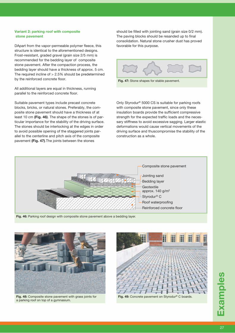
Fig. 44: Concrete slabs laid on Styrodur® C using a pavement slab support system.
Concrete slabs
Air layer
Pavement slab support
Styrodur® C
Roof waterproofi ng
Reinforced concrete fl oor
Fig. 43: Parking roof with small-size reinforced concrete slabs on pavement slab supports.
Fig. 45: Parking roof with concrete slabs laid on an inverted roof with Styrodur C.
27
Exa
mp
les
Variant 2: parking roof with composite stone pavement
DApart from the vapor-permeable polymer fleece, this structure is identical to the aforementioned designs. Frost-resistant, graded gravel (grain size 2/5 mm) is recommended for the bedding layer of composite stone pavement. After the compaction process, the bedding layer should have a thickness of approx. 5 cm. The required incline of > 2.5% should be predetermined by the reinforced concrete floor.
All additional layers are equal in thickness, running parallel to the reinforced concrete floor.
Suitable pavement types include precast concrete blocks, bricks, or natural stones. Preferably, the com-posite stone pavement should have a thickness of at least 10 cm (Fig. 46). The shape of the stones is of par-ticular importance for the stability of the driving surface. The stones should be interlocking at the edges in order to avoid possible opening of the staggered joints par-allel to the centerline and pitch axis of the composite pavement (Fig. 47).The joints between the stones
should be filled with jointing sand (grain size 0/2 mm). The paving blocks should be resanded up to final consolidation. Natural stone crusher dust has proved favorable for this purpose.
Only Styrodur® 5000 CS is suitable for parking roofs with composite stone pavement, since only these insulation boards provide the sufficient compressive strength for the expected traffic loads and the neces-sary stiffness to avoid excessive sagging. Larger elastic deformations would cause vertical movements of the driving surface and thuscompromise the stability of the construction as a whole.
Fig. 48: Composite stone pavement with grass joints for a parking roof on top of a gymnasium.
Fig. 47: Stone shapes for stable pavement.
Composite stone pavement
Jointing sand
Bedding layer
Geotextile approx. 140 g/m2
Styrodur® C
Roof waterproofi ng
Reinforced concrete fl oor
Fig. 46: Parking roof design with composite stone pavement above a bedding layer.
Fig. 49: Concrete pavement on Styrodur® C boards.

28
Variant 3: parking roof with in-situ concrete driving surface
The construction of parking roofs with in-situ concrete driving surface on inverted roofs is recommended for highly frequented parking lots. This construction requires thorough planning and execution. The basic structure of a parking roof with in-situ con-crete driving surface is illustrated in Figures 50 and 51. A separation layer and the in-situ concrete driving surface are installed on top of the load-bearing ceiling structure, the roof waterproofing, and the thermal insu-lation layer of Styrodur® C.
This variant is described in approval Z-23.4-222 as a design of frequented inverted roof constructions.
The planner and the builder must work with a high degree of precision so as to ensure that rainwater is always completely drained through the in-situ concrete driving surface.
Moreover, there are some basic guidelines pertaining to construction and design, and it is most important that these are respected in order to guarantee the long-term reliable operation of parking roofs with in-situ concrete. However, this information does not guarantee their completeness or general validity; it is therefore vital that each case be treated individually by a specialized engineer.
Exa
mp
les
In-situ concrete driving surface
Geotextile approx. 140 g/m2
Styrodur® C
Roof waterproofi ng
Reinforced concrete fl oor
Fig. 50: Basic outline of a parking roof with in-situ concrete driving surface on top of an inverted roof construction with Styrodur® C.
Roof construction:
The incline of the load-bearing reinforced concrete floor must be at least 2%.
The roof waterproofing must be laid in direct contact with the reinforced concrete floor so that, in case of a leakage, no rainwater may seep underneath waterproofing. This makes it easier to locate the damage below the driving surface.
The slope of the roof waterproofing and the in-situ concrete driving surface must be at least 2% and parallel to each other.
Roof drainage:
Roof outlets are to be installed at the lowest points (taking into account sagging roof areas).
Roof outlets with two drainage levels must be instal- led so that, in the case of damage, both the driving surface and the waterproofing layer can be drained without the accumulation of backwater.
The outlets must be inspected and cleaned on a regular basis.
The concrete or cement mixture must be composed of high-quality ingredients in order to keep the drai nage system from sintering as a consequence of lime hydrate flushing out of the weathered in-situ concrete driving surface.
In-situ concrete driving surface:
The in-situ concrete driving surface must have a minimum thickness of 12 cm.
The quality and processing of the concrete must be resistant to long-term frost, weathering, and wear damages. Concrete with high resistance to water penetration is prescribed in accordance with DIN EN 206-1 and DIN 1045-2.
The concrete surface must be abrasion-resistant and slip-proof for driving.
If necessary, the in-situ concrete slabs are to be anchored according to the planner’s specifi- cations for the bearing structure. The measurement of plate reinforcement must be calculated according to the elastic bedding theory.

29
Exa
mp
les
Fig. 51: Parking roof with in-situ concrete driving surface.
Joint formation:
The joints between the in-situ concrete slabs are to be protected from water ingress.
The spaces between the joints should be between 2.5 and 5 m.
The planning and construction of permanent elastic and sealed joints (joint backfill) is to be executed with suitable products and by a specialist.
The durability of parking roofs with in-situ concrete pavement largely depends on the choice, installation, and quality of the joint waterproofing.
Characteristics of insulation material in case of water penetrating the parking roof construction
If the water-draining top layer made of in-situ concrete slabs with joint waterproofing becomes permeable, allowing water to seep underneath the Styrodur® C insulation layer, a worst-case scenario would imply a calculable absorption of moisture into the insulation material. In some areas of the insulation material, mois-ture contents between 10 and 15% by vol. may occur over a period of 20 years. Such values do not affect the static function of the construction. Damages to the insu-lation material due to frost are excluded, although the thermal insulation properties of Styrodur C may decline.
Numerous tests (Fig. 52) and publications have shown that the thermal conductivity of extruded foam rises by about 2.3% per 1% by vol. increase in moisture content.
For example, with a thermal conductivity of 0.034 W/(m·K) in a dry, 50 mm thick Styrodur C board, moisture absorption resulting from the failure of the joint water-proofing would cause thermal conductivity to rise up to 0.042–0.046 W/(m·K). In accordance with approval Z-23.4-222, the rated value of a 50 mm thick board on frequented inverted roofs is specified with 0.037 W/(m·K). Presumably, the deteriorated insulation value would be restricted to areas of the parking roof sur-rounding the drainage area. Therefore, the additional heat loss would remain limited in relation to the total energy requirement of the building.
Approval Z-23.4-222 prescribes Styrodur 4000 CS or Styrodur 5000 CS for frequented in-situ concrete slabs.
Fig. 52: In-situ concrete driving surface slab, sliced for the scientific examination of its long-term behavior.
30
Info
rmat
ion
30
6. Information and General Processing Instructions
Styrodur® C should not be exposed to sunlight for long periods, particularly in summer months.
If Styrodur C is used under covers such as roofing sheets, films, or building protection mats, it is possible that excessive heating could occur during summer due to the absorption of sunlight, which could cause deformation of the Styrodur C boards.
Therefore, it is essential to immediately apply the appropriate protective layer in accordance with the flat roof guidelines.
Styrodur C insulation boards must be permanently protected from UV radiation.
Styrodur C is not resistant to all substances (see brochure “Chemical Resistance” in the down-load area of www.styrodur.de). The instructions of the adhesive manufacturer must be observed for the adhesive selected.
31
Ap
plic
atio
n R
eco
mm
end
atio
ns
for
Sty
rod
ur®
C
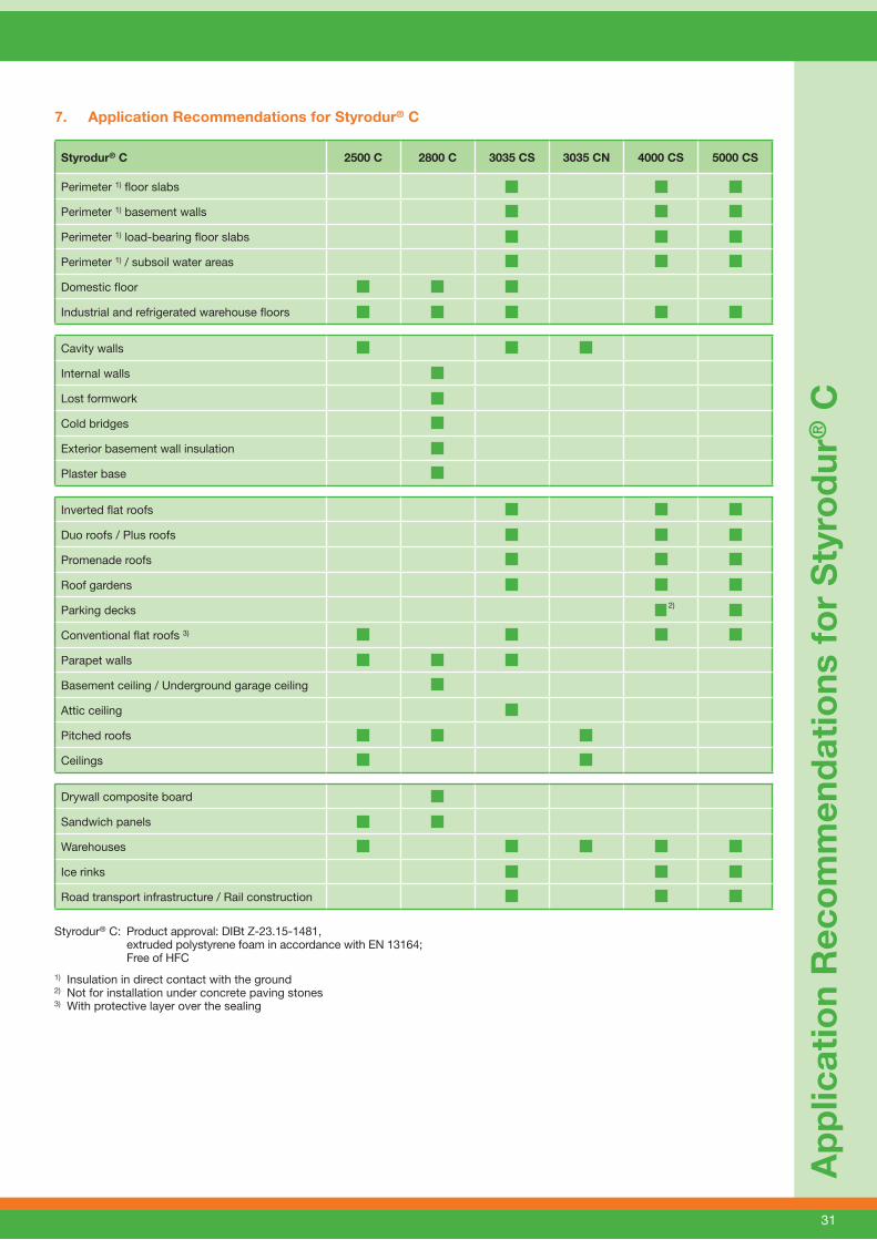
7. Application Recommendations for Styrodur® C
Styrodur® C 2500 C 2800 C 3035 CS 3035 CN 4000 CS 5000 CS
Perimeter 1) floor slabs
Perimeter 1) basement walls
Perimeter 1) load-bearing floor slabs
Perimeter 1) / subsoil water areas
Domestic floor
Industrial and refrigerated warehouse floors
Cavity walls
Internal walls
Lost formwork
Cold bridges
Exterior basement wall insulation
Plaster base
Inverted flat roofs
Duo roofs / Plus roofs
Promenade roofs
Roof gardens
Parking decks 2)
Conventional flat roofs 3)
Parapet walls
Basement ceiling / Underground garage ceiling
Attic ceiling
Pitched roofs
Ceilings
Drywall composite board
Sandwich panels
Warehouses
Ice rinks
Road transport infrastructure / Rail construction
Styrodur® C: Product approval: DIBt Z-23.15-1481, extruded polystyrene foam in accordance with EN 13164; Free of HFC
1) Insulation in direct contact with the ground2) Not for installation under concrete paving stones3) With protective layer over the sealing

KTF
S 1
208
BE
- G
ER
MA
N V
ER
SIO
N -
Jul
y 20
12
Find your local distribution partner on our homepage.
Sty
rodu
r® =
regi
ster
ed tr
adem
ark
of B
AS
F S
E
BASF SE
Performance Polymers Europe67056 LudwigshafenGermany
Styrodur® C—A Strong Product Line
Styrodur 2500 C The light thermal insulation board with smooth
surface and smooth edges for applications with normal compressive strength requirements.
Styrodur 2800 C The thermal insulation board with embossed
honeycomb pattern and smooth edges for application in combination with concrete, plaster, and other covering layers.
Note:The data contained in this publication are based on our current knowledge and experience. In view of the many factors that may affect processing and application of our product, these data do not relieve processors from carrying out their own investigations and tests; neither do these data imply any guarantee of certain properties, nor the suitability of the product for a specific purpose. Any descriptions, drawings, photographs, data, proportions, weights, etc. given herein may be changed without prior notice and do not constitute the agreed contractual quality of the product. It is the responsibility of the recipient of our products to ensure that any proprietary rights and existing laws and legislation are observed.
With the Styrodur® C product line, BASF offers theideal insulation solution for almost every application.
Styrodur 3035 CS The all-round thermal insulation board with
smooth surface and overlap is suitable for almost all applications in structural and civil engineering.
Styrodur 3035 CN The long thermal insulation board with smooth
surface and groove and tongue for quick, thermal bridge-free installation.
Styrodur 4000/5000 CS The extremely compression-proof thermal
insulation board with smooth surface and overlap for applications with highest compressive strength requirement
Styrodur HT The light green, high temperature-resistant
thermal insulation board for all areas of application with thermal loads of up to 105 °C. Further information: www.styrodur.com Styrodur NEO The silver-gray thermal insulation board with an
up to 20% better insulating performance thanks to the use of graphite as an infrared absorber, as patented by BASF. Further information: www.styrodur.com