(fleet iengineering target ssrnm *uuurnuuuuui … · w et al n 4 f/g 7/1i u 'menlflomofleef....
TRANSCRIPT
R D-Ri68 657 FORACS (FLEET OPERATIONAL READINESS ACCURACY CHECK /SITE) TARGET SSRNM (SU..(U) NAVAL FACILITIES
IENGINEERING CO!MANDV MASHINGTON DC CHESAPEAKE.
I UNCLASSFE L MENDL W ET AL N 4 F/G 7/1i U*uuurnuuuuui'MENlflOMOflEEf

ks2.2
L36
1111111L IILA~l'liii-JillI
M B I' ''N

eft Novmbe 18
F (0
PROJAECTE DI CUMISAIONRPR
NAVALFRAC TAITIS NIERGET4AN
W SH RARYINSTALLACT2037
00
NAA ~~FACILTIE NIEMNG AW
~~~~ATMN A~a~g4 9 aalcrlo
C-2
86 6 12 001

DTIC4 S ELECTE
JUN 12 8
~ PROJECT DOCUMENTATION REPORT
FORACS TARGETSSRNM ARRAY INSTALLATION
AUTEC/St. Croix
November 1984
FPO-1-84(31)
Prepared by:Lawrence Mendlow
-. Bruce SchuckmanSandra Vickstrom
Approved:
D. A. Raecke, Director E. B. n cer,.Tech~nical Directorconstruction Division Ocean Engineering and Construction
Project Office
Ii.c \ 1tpub TelDiMti.i~ _____

UnclassifiedSECURITY CLASSIFICATION OF THIS PAGE ......
REPORT DOCUMENTATION PAGEla. REPORT SECURITY CLASSIFICATION lb. RESTRICTIVE MARKINGS
Unclassified
2a. SECURITY CLASSIFICATION AUTHORITY 3. DISTRIBUTION AVAILABILITY OF REApproved for public release;distribution is unlimited
* 2b. DECLASSIFICATION/DOWNGRADING SCHEDULE
4. PERFORMING ORGANIZATION REPORT NUMBER 5. MONITORING ORGANIZATION REPORT"9' FPO-i-84(31)
6a. NAME OF PERFORM. ORG. 6b. OFFICE SYM 7a. NAME OF MONITORING ORGANIZATIOOcean Engineering& ConstructionProject OfficeCHE SNAVFACENGCOM
6c. ADDRESS (City. State, and Zip Code) 7b. ADDRESS (City, State, and ZipBLDG. 212, Washington Navy YardWashington, D.C. 20374-21218a. NAME OF FUNDING ORG. 8b. OFFICE SYM 9. PROCUREMENT INSTRUMENT INDENT
8c. ADDRESS (City. State & Zip) 10. SOURCE OF FUNDING NUMBERSPROGRAM PROJECT TASK WORK UlfELEMENT # * * ACCESS '
11. TITLE (Including Security Classification)FORACS Target SSRNM Array Installation AUTEC/St. Croix: Project DocumentatilReport12. PERSONAL AUTHOR(S)Lawrence Mendlow. Bruce Schuckman & Sandra Vickstrom13a. TYPE OF REPORT 13b. TIME COVERED 14. DATE OF REP. (YYMMDD) 15. PAE
FROM TO 84-11 1816. SUPPLEMENTARY NOTATION
17. COSATI CODES 18. SUBJECT TERMS (Continue on reverse if ne(FIELD GROUP SUB-GROUP FORACS. Arrays. Atlantic Undersea Test ar____-__ __Evaluation Center. St. Croix
19. ABSTRACT (Continue on reverse if necessary & identify by block number)NOSC Code 6362 tasked CHESDIV FPO-1 to install two FORACS Targets at AUTEC.Andros Island, Bahamas and one FORACS Target and c.e SSRNM Array at theUnderwater Tracking Range. St. Croix. USVI.
20. DISTRIBUTION/AVAILABILITY OF ABSTRACT 21. ABSTRACT SECURITY CLASSIFICATI
SAME AS RPT.22a. NAME OF RESPONSIBLE INDIVIDUAL 22b. TELEPHONE 22c. OFFICE SYMB(
Jacqueline B. Riley 202-433-3881DD FORM 1473, 84MAR SECURITY CLASSIFICATION OF THIS PA
++i ,.+ . . . J . - . + Jr - . . *** *,. -C ' , . .... -. .

" CTABLE OF CONTENTS
* List of Tables iiiList of FiguresList of Acronyms iv
-' 1.0 Management Summary 11.1 Background I1.2 System Description - FORACS 11.3 System Description - SSRNM 31.4 Construction Site - AUTEC 31.5 Construction Site - St. Croix 31.6 Construction Planning Summary 51.7 Construction Operations Summary 5
2.0 Location Details 72.1 Geographical Data, Site Plan, and System Element
Locations 7
3.0 Installation Details 73.1 Installation Details/Comparison with Specifications 7
4.0 Recommendations for Future SSRNM Installations 11
Accesion For
NTIS CRA&IOTIC TAB 03Unannounced 1justification ... .. ......
By ...... . ......
Dist. ibuton
Availability CodesAvail and I r
Dist Special
[A -,

LIST OF TABLES
2.1 AUTEC Installed Locations 8- 2.2 St. Croix Installed Locations 10
LIST OF FIGURES
1.1 FORACS Target 21.2 SSRNM Array 4
. 2.1 AUTEC Installations 92.2 St. Croix Installations 113.1 SSRNM Termination Device 13
• , ,WO
1 i
'-p

LIST OF ACRONYMS
d CHESDIV Chesapeake Division, Naval Facilities,- - Engineering Command.
" NOSC Naval Ocean Systems Center.
UCT-1 Underwater Construction Team One.
APL Applied Physics Laboratory, Universityof Washington.
. AUTEC Atlantic Underwater Test and EvaluationCenter.
AFWTF Atlantic Fleet Weapons TrainingFacility.
UTR St. Croix Underwater Tracking Range.
DTNSRDC David W. Taylor Naval Ship Research andDevelopment Center.
SUPSALV Supervisor of Salvage, Naval SeaSystems Command.
BIW Boston Insulated Wire Company.
FORACS Fleet Operational Readiness Accuracy. J-. Check Site.
SSRNM Surface Ship Radiated Noise Measurement.
V'Il
. . '
,
.. i
2-. .qp- - - - - - - - - - - -

1.0 MANAGEMENT SUMMARY
I 1.1 Background
NOSC Code 6362 tasked CHESDIV FPO-1 to install two FORACS-. Targets at AUTEC, Andros Island, Bahamas and one FORACS Target and
one SSRNM Array at the Underwater Tracking Range, St. Croix, USVI.The organizations that participated in the project were:
1) NOSC - Funding, SSRNM Equipment and ET's.
S.-2) CHESDIV - Installation Planning, Installation Coordination,"' SEACON.
3) UCT-1 - Deckforce, Installation Planning.
..4) APL - FORACS Equipment and Engineers, FORACS TargetsPositions.
5) AUTEC - On-site Logistics.
6) AFWTF - On-site Logistics.
NOSC funded the project through the following documents:
N66001 83WR 00412 $30,000.00 23 JUN 1983, N66001 83RC 00097 $100,000.00 10 AUG 1983
N66001 84WR 00086 $10,000.00 4 NOV 1983N66001 84WR 00214 $137,000.00 19 JAN 1984
, . N66001 84RC 00053 $78,000.00 8 FEB 1984N66001 84WR 00391 $45,000.00 23 APR 1984N66001 84WR 00491(Amend 1) $4.000.00 22 MAY 1984N66001 84RC 00094 $32,000.00 22 MAY 1984
1.2 System Description - FORACS
FORACS ranges consist of a series of radar and acoustic targetsused to check the accuracy of a ship's sensors. CHESDIV was taskedto install several acoustic targets (a deep and shallow water targetat AUTEC and a deep water target at St.Croix with a backup to beinstalled as a shallow water target at St.Croix if time permitted).
" See Figure 1.1 for a typical FORACS acoustic target.
Each target is separately cabled back to shore (with Simplex.057/.180 Quad Cable) and into a control panel located in thecontrol room of the appropriate facility. CHESDIV efforts consisted
- iof bringing the cable to the on-shore termination boxes. Theconnections to the termination boxes and the cabling and connectionsbetween the boxes and the control panel were carried out by thefacility and APL.
i"A

-w w-- .-- wv-w-L-wt--wv'rr"r ~ r~"F1r r- W Y-' r.C W-? - - -..~ ".,
N.
V.S.
/
- ri
N.
N.
FURACS Target
Figure 1.1
-p
V N.is'.,
2
..-..
~* ~ .-.- c*~.- - - - - - - . - . . - . . . . - - - - --.--. ..-.- '-- '--. - ~ - .-

The targets were designed and built by APL. The targetlocations were selected by APL after consultation with therespective facilities. The position was not considered critical sothere was no specification of accuracy in the X-Y plane.
However, depth was considered important and specifications fordepth were given; for the shallow targets the depth was permitted tovary from the selected depth to 10 ft deeper than the selecteddepth. For the deep targets the depth was to be between 1200 and
t- 1300 feet. However this was permitted to be varied on site with theconsent of the APL engineer on board.
1.3 System Description - SSRNM
The SSRNM system is a vertical acoustic array designed toanalyze the acoustic signature of a surface ship. The SSRNM arrayconsists of a subsurface float, a Kevlar strength member, electricalcables and four hydrophones. The array was also designed to have apowered pinger on it for 3-D location on the range. The array isheld in position by a concrete clump (17.000 lbs in air, 9,600 lbs
S in water). A specially designed cable connects the array to shore,with transformers in a junction chamber at the base of the array toinsure proper signal strength/impedance. On shore is an electronicsvan where all the signal processing occurs. See Figure 1.2 forSSRNM Array.
The array was designed and built by NOSC in conjunction with0 DTNSRDC. The location was provided by NOSC and the UTR. Once againvertical control was considered more important than horizontalcontrol. Horizontally, a several hundred foot error was considered
r acceptable, but vertically, the top of the buoy had to be between adepth of 100 ft and 120 ft, based on the draft of large tankers anddiver limitations.
1.4 Construction Site - AUTEC
AUTEC is located on Andros Island, Bahamas. It consists of anacoustic range, a weapon range and a FORACS range with all thesupport facilities to maintain the base, the ranges and all theequipment that the ranges use. The cable landing site was inside a
--.'- [ cut in the reef permitting SEACON to approach no closer than 1 milefrom shore and necessitated use of an AUTEC LCM-6 to pull the cableto shore. An existing cable trench was used to route the cable fromthe beach to the Command and Control building.
- -1.5 Construction Site - St. Croix
The St.Croix UTR under the cognizance of AFWTF, Roosevelt Roads,PR is located at Sprat Hall, 1 mile north of Frederiksted, ST.Croix,USVI.
3

IviELDFD ~bOLTED
UCYNET eUOYANCY 4170 LBS
HYDROPHONE -2
r K_____2631 FT.Ii HYDROPHONE =3
2b1 3 FT. ~7
HYDROPHONE UL4
IEl "'AP CE
;EXTRA 300 FT. OF 7 K__SECUR7D 1-0 BRACK<ET __________________-
C9LMP PLP STOPPER 'STRAIN RELIER
'D02 L BS. WATP
-p-p SSRNM ARRAY
Figure 1.2
4

m v
The facility overlooks the beach landing site on a steep 30 fthigh bluff. The shore drops off fairly quickly, permitting SEACONto approach within 1200 ft of the shore.
1.6 Construction Planning Summary
S: 23 Jun 83 Original tasking for FORACS/SSRNMInstallation.
17 Nov 83 Dates of Installation and use of SEACONfinalized.
19 Jan 84 Op order 2-84 promulgated.
20 Mar 84 Project Execution Plan - FPO-1-84(l)promulgated.
20 May 84 Addendum to PEP promulgated.
22 May 84 Op order 3-84 promulgated.
1.7 Construction Operations Summary
13-18 Feb 1984 SEACON towed from Norfolk, VA to FortLauderdale. FL.
19-30 Mar SEACON and project mobilization at FortLauderdale. FL. The effort includedthe assembly of the FORACS structures.the winding of the electrical cablesand the Kevlar rope onto Pengo reels.and loading the SSRNM cable in SEACON'scable tank.
31 Mar - 1 Apr SEACON transited to AUTEC.
2 Apr CHESDIV personnel setup Minirangershore stations. UCT-1 and AUTECpersonnel set up the beach site forhauling the cable ashore.
3-4 Apr Installed deep water FORACS Target.
5-6 Apr Installed shallow water FORACS Target.
7 Apr UCT-1 and CHESDIV personnel pulled thenear shore portion of the cables intoposition and demobilized the shoresites. SEACON departed AUTEC.
8-13 Apr The USS PAPAGO. ATF 160, towed SEACONto NAVSTA Roosevelt Roads. PR.
5

13-14 Apr Picked up the SSRNM clump and theFORACS cable for St.Croix Operations atNAVSTA Roosevelt Roads. Wound theFORACS cable on Pengo reel.
15 Apr SEACON transited to St.Croix.
16 Apr UCT-1 and CHESDIV personnel set up theshore site.
17 Apr Plumbed the SSRNM site and cut theSSRNM Kevlar strength member to matchthe depth at the installation site.
-NOSC personnel installed a new socketon the Kevlar strength member.
18 Apr Installed deep & shallow FORACS Targets.
19 Apr Equipment failure caused loss of SSRNMclump/shore cable/junction chambers.
29 Apr With SUPSALV personnel using Deep Droneaboard USNS MOHAWK, T-ATF 170, theclump was recovered aboard SEACON.
30 Apr Recovered the shore cable into theSEACON's cable tank.
I May UCT-1 and CHESDIV personnel broke downthe shore site. SEACON transited toNAVSTA Roosevelt Roads.
14-18 May BIW reterminated the SSRNM cable onboard SEACON.
23-25 May SEACON mobilized at NAVSTA RooseveltSRoads.
25-26 May SEACON transited to St.Croix.
26 May Set up the shore site.
27-28 May Installed the SSRNM array.
28 Ma, Demobilized the shore site.
28-29 May SEACON transited to NAVSTA RooseveltRoads, PR.
30 May Demobilized SEACON
6
der."- -''

'S T
2.0 LOCATION DETAILS
2.1 Geographical Data, Site Plan & System Element Locations
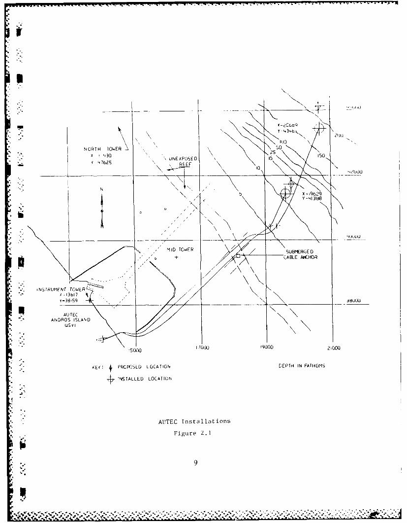
AUTEC is located at Andros Island Bahamas. The FORACS Rangeuses a local grid with the North Tower as the origin and the Y axis
*:. at an azimuth of 305.90. CHESDIV chose to use a grid system basedon true north and selected on old AUTEC construction grid. In thissystem the location of the North Tower is (11430 X. 47625 Y). Toconvert from the FORACS grid to this grid system use the followingformulas:
Xcg = Xf Cos(305.9) - Yf Sin(305.9) + 11430Ycg = Xf Sin(305.9) + Yf Cos(305.9) + 47625
To convert from the construction grid to the FORACS grid use thefollowing formulas:
Xf = (Xcg - 11430) Cos(305.9) + (Ycg - 47625) Sin(305.9)Yf = (Xcg - 11430) Sin(305.9) + (Ycg - 47625) Cos(305.9)
The conversion from latitude/longitude to FORACS grid is done by therange. The North Tower and the Instrument Tower were used asminiranger transponder stations. The location of the minirangerstations and installed targets are shown in Table 2.1 and Figure 2.1.
The St.Croix Underwater Tracking Range is located on the westside of St.Croix, north of Frederiksted. The range uses a localgrid based on a rotation and translation of UTM coordinates. Thiswas the system used for this project. Conversion betweenlatitude/longitude and the grid system is accomplished by therange. Sprat Hall and the Coast Guard Light at the foot of
IL Frederiksted Pier were used as miniranger shore transponder sites.The locations of the miniranger sites, the FORACS targets and theSSRNM array system are shown in Table 2.2 and Figure 2.2.3.0 .STALLATION DETAILS
3.1 Installation Details/Comparison with Specifications
The FORACS target was a package provided by APL and installationwent as planned. No changes in the design were required. However,there was a break in the cable during the installation of theshallow FORACS target at AUTEC. The splice to reconnect the cable
* is in the cable trench well on shore. What was learned from thisexperience is that the shallow FORACS targets are diver repairable.
. , By simply removing the bolts from the chamber flange connection anddisconnecting the underwater mateable connectors, the chamber can bebrought to the surface. All location changes were as a result ofwater depth requirements and agreed to by APL. A comparison betweenthe planned and the installed locations is shown in Table 2.1.
7

I>o 0- N i
0 0 4 N 14 N 1
L) 0
00 '0 0' H ON q k
E-Z 0 m cl
I-4Q inI 14 H4 0
" N LO %0 m~ OD ai
0 E4 -4
0 0 cv 0 H
000
0 (n N 0 0 0% N0(u H 04 r4 N r4 -
0 0. 0. 4) '
M z
Z n 0% 0- 0 0 0 0
%Dr N 0 0 Ho 0 4.)
I-,4
E-4)
E-0N i 0 0 0 0
H - rLi 0 0% 0 % a
U) U,W E- U 0 E-4
0 0)
E-4 0-4
6-3a0 z- 0 U0 0
opt
U,%
Y-,Ui-- 4ltb
NORTH TOWER CS50
X '430 UNEXPOSED 1 5 ISO
Y L#-7625 R FEEF 10
N
INTUMFNT TOWERX -13617
Y-3861; JbUU
AUTECANDROS ISLAND
uS VI
5000 1&~ 19000 21000
KEV 4 PRCrjSED LOCATION DEPTH IN FATHOMS
+INSTALLED LOCATION
A17TEC Installations
Figure 2. 1
9

-I,%._ m
PLANNED LOCATION INSTALLED LOCATIONSITE X (E) Y (N) X Y
SPRAT 61,998 37,859 61,998 37.859
COAST GUARD LIGHT 64,850 28,375 64,850 28.375
DEEP FORACS TARGET 58,302 28,774 58,487 29.521
- HOLD POINT FOR DEEP LFTS 60,400 36,975 60,610 36,985
SHALLOW FORACS TARGET 60.334 34.225 60.584 34.311
HOLD POINT FOR SHALLOW LFTS 60,400 36,975 60,722 37.290
HOLD POINT FOR SSRNM ARRAY 60,279 37,333 60,623 37.054
SSRNM ARRAY 52,986 35,029 53,063 35,023
Note: All coordinates are in feet.
°% -'
ST. CROIX INSTALLED LOCATIONS
Table 2.2
10
4; _ - , .' ;' ', * , - ' w# -. '"z - , ,, . w,, . ..
. ," '

E50000 E 60000
_____ ____N140000
Y= 3L7859
SSRNM
Y=3528375
0/* ~ ~ ~ : PRPOE TARGE LOATO DETHIRFT O
n ~ ~ ~ ~ ~ ~ OA MIIRNESHOESAINX 066
S.3 Cri 34s3ll4ion
Figure02.2
11 AC
X=58487'

J %
The SSRNM array, see Figure 1.2, was changed from the original
r considerations:
A. The original design was based on a 3000 ft water depth, the
selected site was only 2700 ft. and required that 300 ft of Kevlar% strength member be cut off and the Keviar reterminated.
B. The triangular termination device was modified to hold theextra electrical array cable (300 ft) and provide a better strainrelief system. See Figure 3.1.
btC. Due to the break in the Kevlar strength member a splice
between two Kevlar lengths exists about 100 ft above the clump.
D. While attempting to install the pinger. the back plate ofthe support bracket was lost over the side. No spare was availableso the pinger was not installed. If needed divers can install a newpinger, but depth capabilities to 200 ft will be required by thedivers used because the pinger pigtail came up approximately 50 ftshort of the bottom of the buoy and not the 5 ft as planned.
E. The double buoy system was welded together as well as bolted.
-VK F. The location of the SSRNM is off by 77 ft to the east.
G. The depth of the top of buoy was measured by diver at142 ft, 28 ft deeper than measured by the lowering line during theinstallation. The obvious answer as to why the depth is differentthan when plumbed and measured is due to the location difference.However this does not explain why the bottom of the buoy measured122 ft deep during installation and 150 ft deep the next day. Thisis due to the stretch of the Kevlar whilc supporting the 9.600 lbweight less the 4,200 lb buoyancy from the float holding up the
, array. At 1% stretch, this amounts to 26 feet which is close to the28 ft observed.
4.0 RECOMENDATIONS FOR FUTURE SSRNM INSTALLATIONS
1. All components should be assembled and pressure tested andelectronically tested prior to installation operations. Thestrength member should be marked for hydrophone locations not justlength indications.
2. All components should be designed to take installation loads notjust installed loads.
3. When depth is as critical as the specifications stated, a bettermethod of placing the array at the desired depth should bedeveloped. This may require a redesign of the array itself, such asusing a two-point spread moor rather than the single point moor that
... . was installed.
S-*.. *-, 12

-c .. .- -H--.
-44
U m E/
0
4.-4
co~
-Il
U-'\
41-
0_ ~
'-4 1-4
caHp.
~~No
-H e~13
r r.- n. r"r -- ..
4. For all ocean operations, have spares for everything, especiallyI small pieces that are being handled over the side of the vessel.
5. Mark length of electrical cable (every 100 ft).
6. The array electrical cable length should incorporate a givenpercentage of slack in order to accommodate a tension freeconnection to the mechanical cable.
7. Mark length of shore cable (every 1000 ft or .1 NM).
8. Reduce in-air weight/size of clump to make installation handlingeasier.
D14
'p.. -
[ .. I. , '
[., "' "
[ -,,, -14

99
9
K5'.
L.
S..
"a ~
S
~ %~s.s.~* * ~ -~~'v~' *;; ~., .~. - - . - -.. '-.- - -. *~~~'~S~S.~~-~.