flessibilità ed efficienza nella generazione elettrica da ... · flessibilità ed efficienza nella...
TRANSCRIPT
Process and Energy Systems Process and Energy Systems
Engineering LaboratoryEngineering Laboratory
Process and Energy Systems Process and Energy Systems
Engineering LaboratoryEngineering Laboratory
Flessibilità ed Efficienza nella Generazione Elettrica da Combustibili Fossili
Giuseppe Messina
Secondo Workshop Nazionale Simulazione del sistema energetico e della
sua sostenibilità
Roma 5-6 Luglio 2016

Programmable Power Plants Flexibility
Recoding of Combined Cycles Power Plants
Power Plants vs Large Energy Systems Modelling
Conclusions
Agenda Sustainable Combustion
& Processes Laboratory
Process and Energy Systems Process and Energy Systems
Engineering LaboratoryEngineering Laboratory
Process and Energy Systems Process and Energy Systems
Engineering LaboratoryEngineering Laboratory
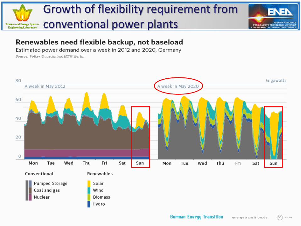
Growth of flexibility requirement from conventional power plants
Process and Energy Systems Process and Energy Systems
Engineering LaboratoryEngineering Laboratory
Process and Energy Systems Process and Energy Systems
Engineering LaboratoryEngineering Laboratory
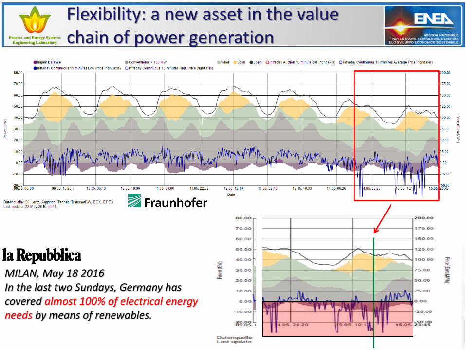
Flexibility: a new asset in the value chain of power generation
MILAN, May 18 2016 In the last two Sundays, Germany has covered almost 100% of electrical energy needs by means of renewables.
Process and Energy Systems Process and Energy Systems
Engineering LaboratoryEngineering Laboratory
Process and Energy Systems Process and Energy Systems
Engineering LaboratoryEngineering Laboratory
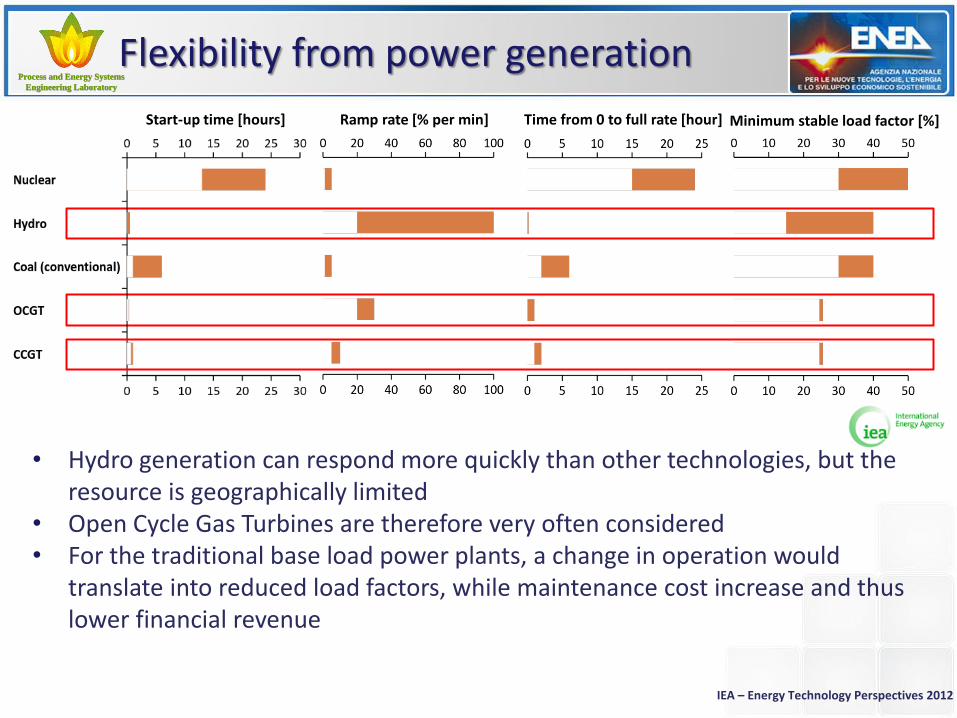
Flexibility from power generation
IEA – Energy Technology Perspectives 2012
• Hydro generation can respond more quickly than other technologies, but the resource is geographically limited
• Open Cycle Gas Turbines are therefore very often considered • For the traditional base load power plants, a change in operation would
translate into reduced load factors, while maintenance cost increase and thus lower financial revenue
Start-up time [hours] Ramp rate [% per min] Time from 0 to full rate [hour] Minimum stable load factor [%]
Process and Energy Systems Process and Energy Systems
Engineering LaboratoryEngineering Laboratory
Process and Energy Systems Process and Energy Systems
Engineering LaboratoryEngineering Laboratory
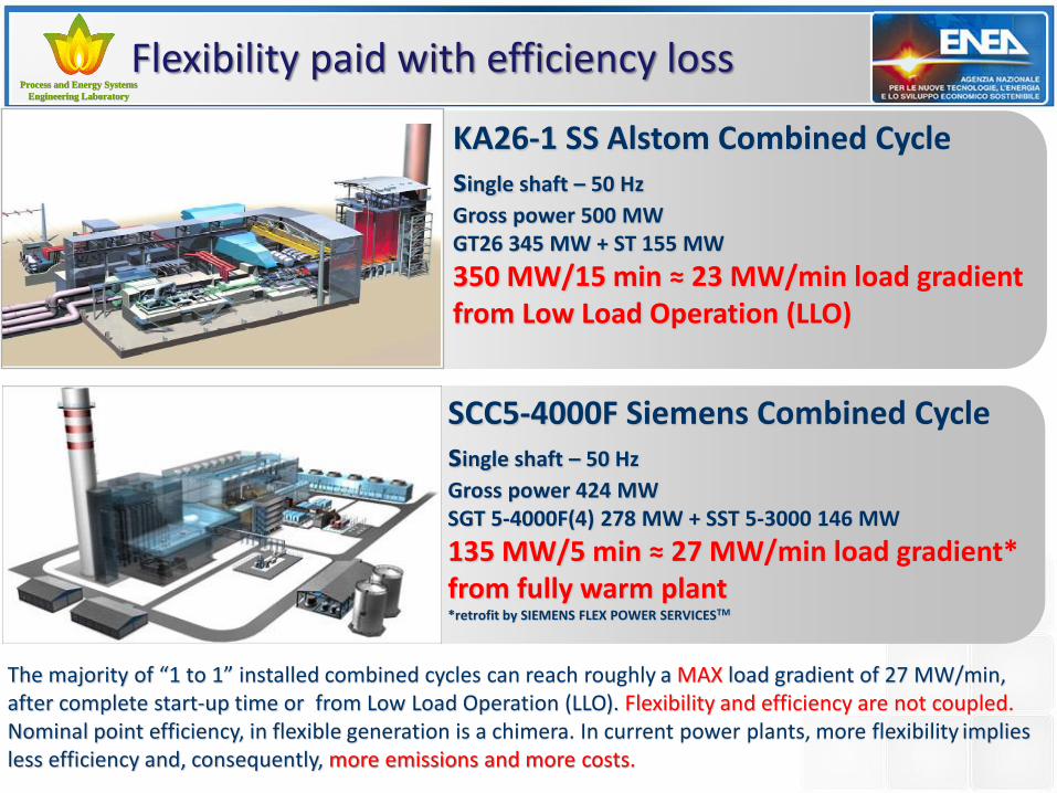
Flexibility paid with efficiency loss
The majority of “1 to 1” installed combined cycles can reach roughly a MAX load gradient of 27 MW/min, after complete start-up time or from Low Load Operation (LLO). Flexibility and efficiency are not coupled. Nominal point efficiency, in flexible generation is a chimera. In current power plants, more flexibility implies less efficiency and, consequently, more emissions and more costs.
SCC5-4000F Siemens Combined Cycle single shaft – 50 Hz
Gross power 424 MW SGT 5-4000F(4) 278 MW + SST 5-3000 146 MW
135 MW/5 min ≈ 27 MW/min load gradient* from fully warm plant *retrofit by SIEMENS FLEX POWER SERVICESTM
KA26-1 SS Alstom Combined Cycle single shaft – 50 Hz
Gross power 500 MW GT26 345 MW + ST 155 MW
350 MW/15 min ≈ 23 MW/min load gradient from Low Load Operation (LLO)
Process and Energy Systems Process and Energy Systems
Engineering LaboratoryEngineering Laboratory
Process and Energy Systems Process and Energy Systems
Engineering LaboratoryEngineering Laboratory
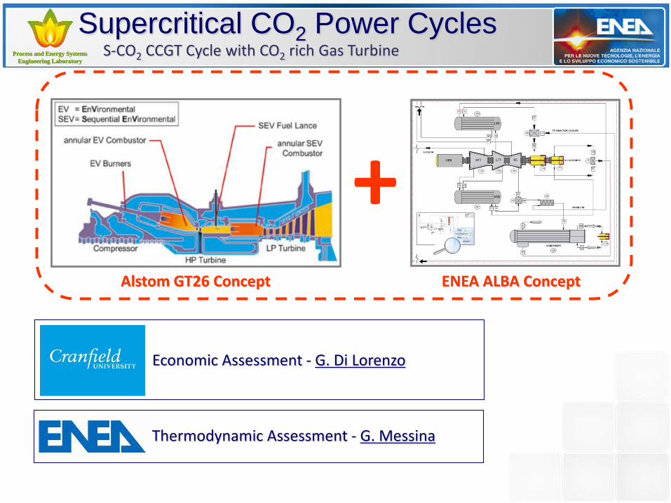
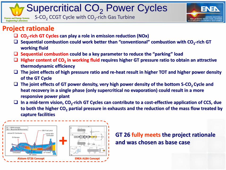
Supercritical CO2 Power Cycles S-CO2 CCGT Cycle with CO2 rich Gas Turbine
+ Alstom GT26 Concept ENEA ALBA Concept
Economic Assessment - G. Di Lorenzo
Thermodynamic Assessment - G. Messina
Supercritical CO2 Power Cycles S-CO2 Peculiarities Sustainable Combustion
& Processes Laboratory

Process and Energy Systems Process and Energy Systems
Engineering LaboratoryEngineering Laboratory
Process and Energy Systems Process and Energy Systems
Engineering LaboratoryEngineering Laboratory
Messina G., Giacomazzi E.: “Modelling of a 48 MWt Supercritical CO2 Power Cycle Powered by the ISOTHERM® PWR Loop” – Technical Report RdS/2013/298 – Electric System Research – ENEA - Italian Ministry of Economic Development - Program Agreement, 2013 (in Italian)
Cycle 1st pressure level: 1 (600 °C – 250 bar) to 2 (428 °C – 58 bar): HT Expansion 2 to 3 (65 °C 57 bar): HTR output heat transfer 3 to 7 (217 °C 263 bar): Re-compression 3’ (62 °C – 56.75 bar) to 4 (18 °C – 55.1 bar): Cooling & Condensing 4 to 5 (51 °C – 268 bar): 1st level pumping 5 to 8 (252 °C – 263 bar): LTR input heat transfer 8 to 1: heat transfer input from heat source
Supercritical CO2 Power Cycles Bottoming S-CO2 Closed Cycle
Cycle 2nd pressure level: 3’ (62 °C – 56.75 bar) to 4 (18 °C – 55.1 bar): Cooling & Condensing 4 to 6 (55 °C – 300 bar): 2nd level pumping 6 to 9 (416 °C – 294 bar): HTR input heat transfer 9 to 10 (251 °C – 58 bar): LT expansion 10 to 3: LTR output heat transfer
ENEA works continuously at Advanced Liquid Compression BrAyton (ALBA) concept as a category of closed and semi-closed S-CO2 cycles with “phase-balanced” compression to increase both efficiency and compactness of fossil fuel power plants.
Cycle Efficiency: 40.58%
Process and Energy Systems Process and Energy Systems
Engineering LaboratoryEngineering Laboratory
Process and Energy Systems Process and Energy Systems
Engineering LaboratoryEngineering Laboratory
Supercritical CO2 Power Cycles S-CO2 CCGT Cycle with CO2-rich Gas Turbine
+AlstomAlstom GT26 ConceptGT26 Concept ENEA ALBA ConceptENEA ALBA Concept
+AlstomAlstom GT26 ConceptGT26 Concept ENEA ALBA ConceptENEA ALBA Concept
Project rationale CO2-rich GT Cycles can play a role in emission reduction (NOx) Sequential combustion could work better than “conventional” combustion with CO2-rich GT
working fluid Sequential combustion could be a key parameter to reduce the “parking” load Higher content of CO2 in working fluid requires higher GT pressure ratio to obtain an attractive
thermodynamic efficiency The joint effects of high pressure ratio and re-heat result in higher TOT and higher power density
of the GT Cycle The joint effects of GT power density, very high power density of the bottom S-CO2 Cycle and
heat recovery in a single phase (only supercritical no evaporation) could result in a more responsive power plant
In a mid-term vision, CO2-rich GT Cycles can contribute to a cost-effective application of CCS, due to both the higher CO2 partial pressure in exhausts and the reduction of the mass flow treated by capture facilities
GT 26 fully meets the project rationale and was chosen as base case

Process and Energy Systems Process and Energy Systems
Engineering LaboratoryEngineering Laboratory
Process and Energy Systems Process and Energy Systems
Engineering LaboratoryEngineering Laboratory
Power Plants vs Energy Systems Modelling
8 hours of continuative running
Process and Energy Systems Process and Energy Systems
Engineering LaboratoryEngineering Laboratory
Process and Energy Systems Process and Energy Systems
Engineering LaboratoryEngineering Laboratory
Turbec T100 mGT Modelling
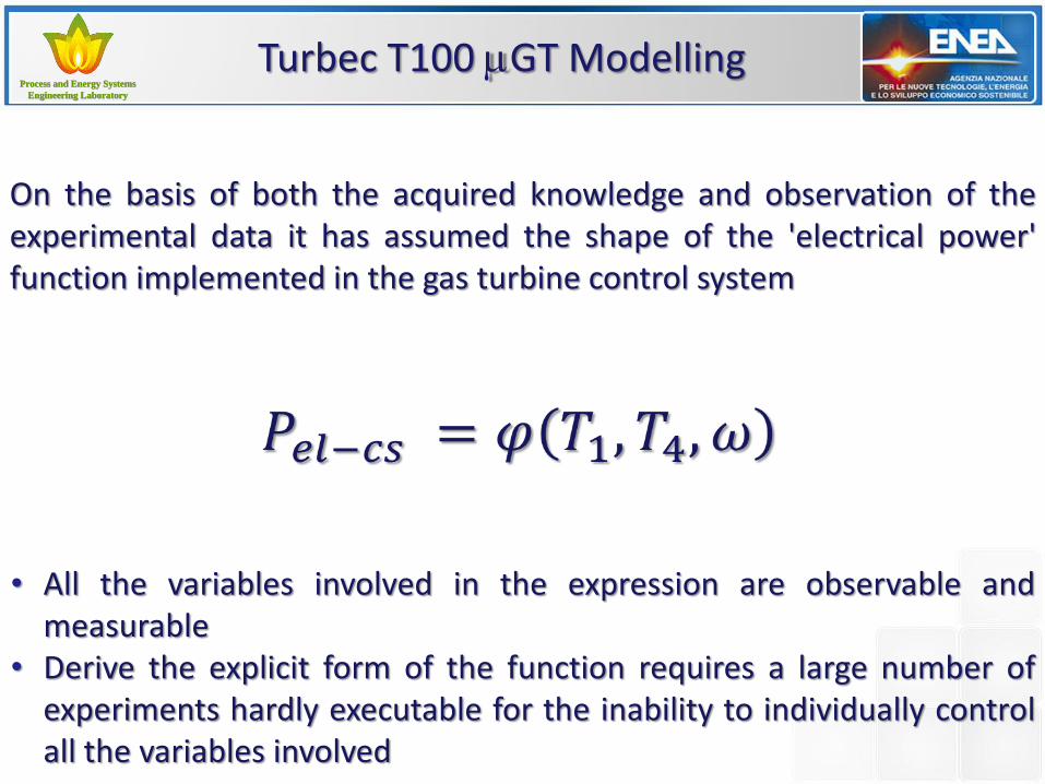
• All the variables involved in the expression are observable and measurable
• Derive the explicit form of the function requires a large number of experiments hardly executable for the inability to individually control all the variables involved
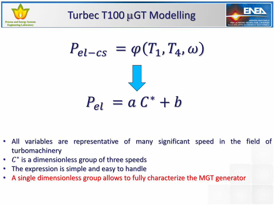
On the basis of both the acquired knowledge and observation of the experimental data it has assumed the shape of the 'electrical power' function implemented in the gas turbine control system
Process and Energy Systems Process and Energy Systems
Engineering LaboratoryEngineering Laboratory
Process and Energy Systems Process and Energy Systems
Engineering LaboratoryEngineering Laboratory
Turbec T100 mGT Modelling
• All variables are representative of many significant speed in the field of turbomachinery
• 𝐶∗ is a dimensionless group of three speeds • The expression is simple and easy to handle • A single dimensionless group allows to fully characterize the MGT generator
Process and Energy Systems Process and Energy Systems
Engineering LaboratoryEngineering Laboratory
Process and Energy Systems Process and Energy Systems
Engineering LaboratoryEngineering Laboratory
Turbec T100 mGT Modelling
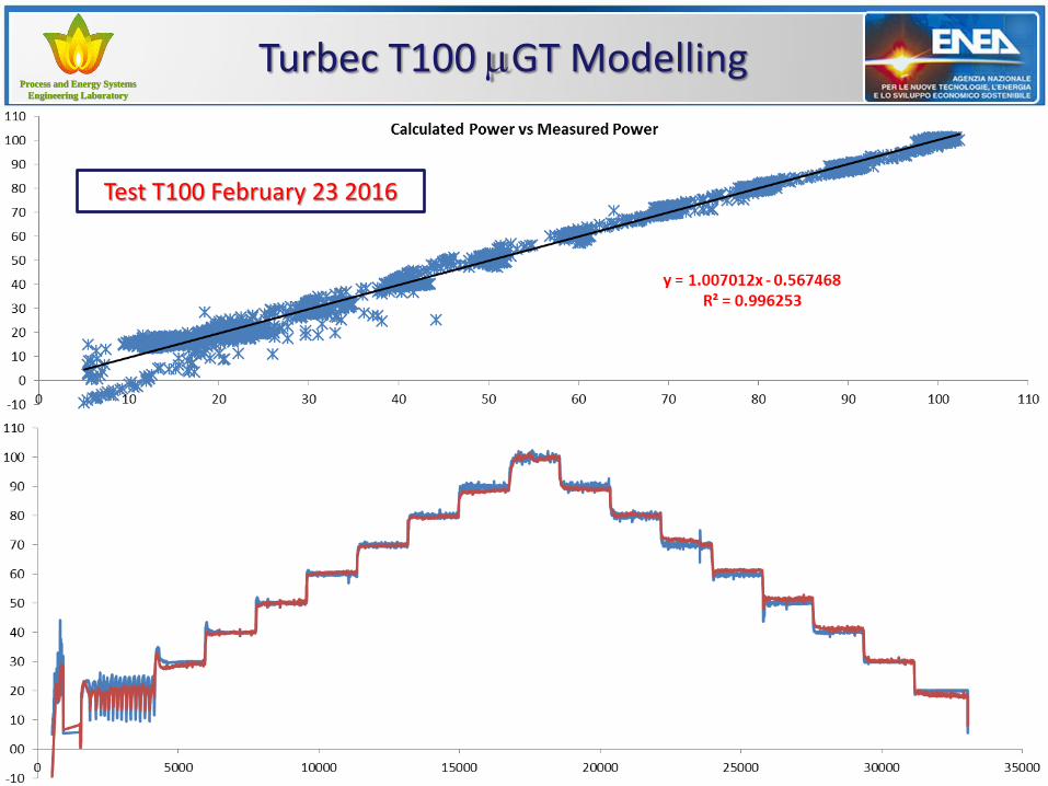
Test T100 February 23 2016
Process and Energy Systems Process and Energy Systems
Engineering LaboratoryEngineering Laboratory
Process and Energy Systems Process and Energy Systems
Engineering LaboratoryEngineering Laboratory
Turbec T100 mGT Modelling
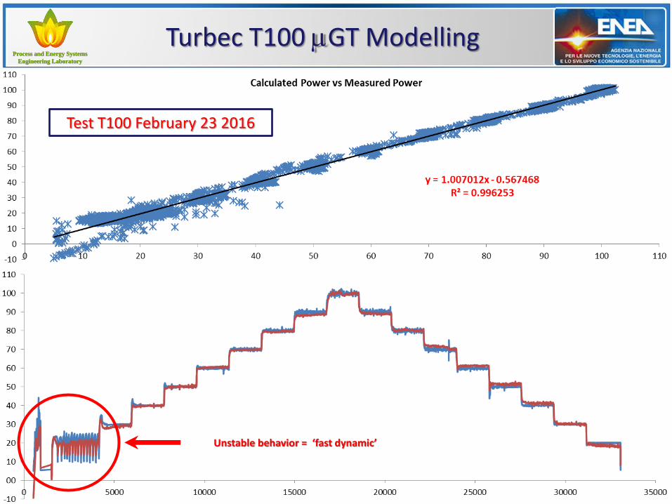
Test T100 February 23 2016
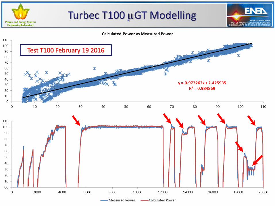
Unstable behavior = ‘fast dynamic’
Process and Energy Systems Process and Energy Systems
Engineering LaboratoryEngineering Laboratory
Process and Energy Systems Process and Energy Systems
Engineering LaboratoryEngineering Laboratory
Test T100 February 19 2016
Turbec T100 mGT Modelling
Process and Energy Systems Process and Energy Systems
Engineering LaboratoryEngineering Laboratory
Process and Energy Systems Process and Energy Systems
Engineering LaboratoryEngineering Laboratory
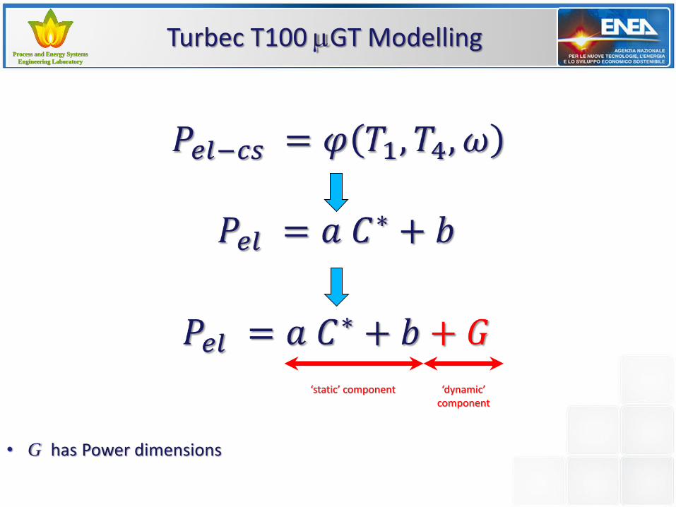
• G has Power dimensions
Turbec T100 mGT Modelling
‘static’ component ‘dynamic’ component
Process and Energy Systems Process and Energy Systems
Engineering LaboratoryEngineering Laboratory
Process and Energy Systems Process and Energy Systems
Engineering LaboratoryEngineering Laboratory
Turbec T100 mGT Modelling
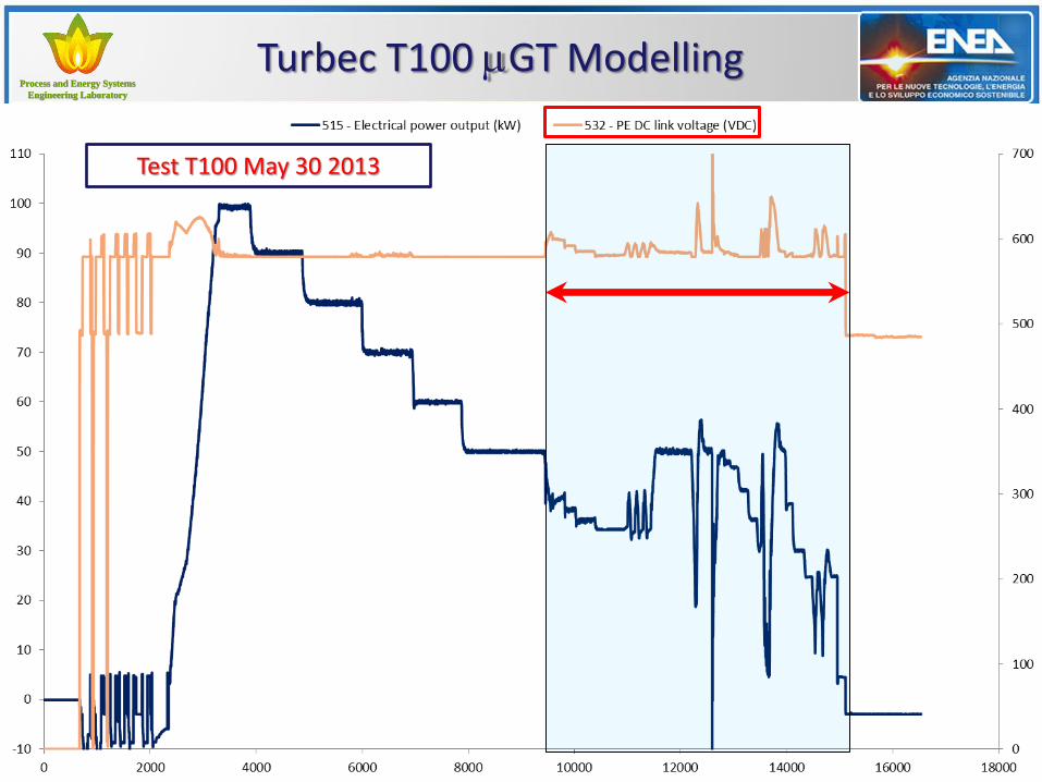
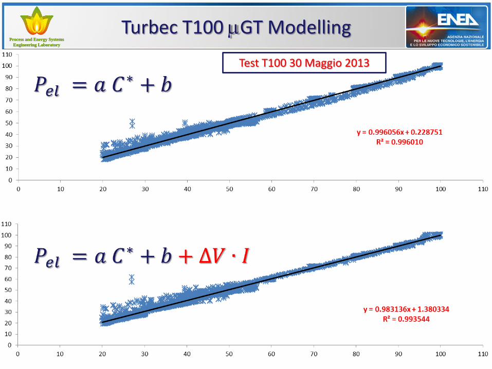
Test T100 May 30 2013

Process and Energy Systems Process and Energy Systems
Engineering LaboratoryEngineering Laboratory
Process and Energy Systems Process and Energy Systems
Engineering LaboratoryEngineering Laboratory
Turbec T100 mGT Modelling
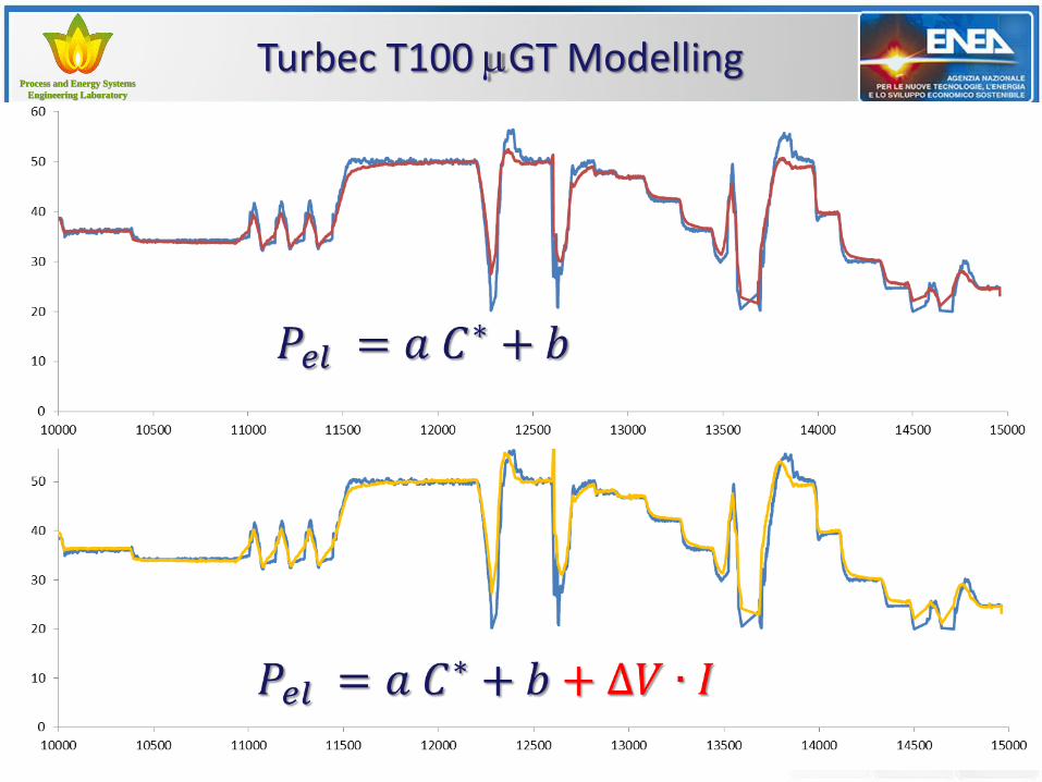
• ∆𝑉 ∙ 𝐼 It is the product of the of the DC-link voltage change to the current.
‘static’ component ‘dynamic’ component
Process and Energy Systems Process and Energy Systems
Engineering LaboratoryEngineering Laboratory
Process and Energy Systems Process and Energy Systems
Engineering LaboratoryEngineering Laboratory
Turbec T100 mGT Modelling
Test T100 30 Maggio 2013

Process and Energy Systems Process and Energy Systems
Engineering LaboratoryEngineering Laboratory
Process and Energy Systems Process and Energy Systems
Engineering LaboratoryEngineering Laboratory
Turbec T100 mGT Modelling
Test T100 May 30 2013
Process and Energy Systems Process and Energy Systems
Engineering LaboratoryEngineering Laboratory
Process and Energy Systems Process and Energy Systems
Engineering LaboratoryEngineering Laboratory
Turbec T100 mGT Modelling
Process and Energy Systems Process and Energy Systems
Engineering LaboratoryEngineering Laboratory
Process and Energy Systems Process and Energy Systems
Engineering LaboratoryEngineering Laboratory
Turbec T100 mGT Modelling
• The approach has been validated with a large number of experimental data, in unstable operation conditions of the machine, on machines that expose very different dynamic response.
• The approach includes both the scalability and generality requirements, derived from the expression of 𝐶∗:
1. Turbine a gas di dimensione e potenza diversa 2. Turbine a gas operanti con fluidi di lavoro diversi dall’aria
Process and Energy Systems Process and Energy Systems
Engineering LaboratoryEngineering Laboratory
Process and Energy Systems Process and Energy Systems
Engineering LaboratoryEngineering Laboratory
Conclusions
• The increasing penetration of renewable require ever greater flexibility from programmable power generation
• Large-scale energy systems modelling must include the correct encoding of the power plant flexibility as a technical-economic variable of the model
• The coupling of large scale system models with power plant models, with reasonable computational resources, requires a "light" power plants encoding: to look to the control systems instead of physical systems could be a solution.
Grazie per la cortese attenzione
www.enea.it
Sustainable Combustion
& Processes Laboratory