flex cam – training. understand the concept find the information select components install the...
TRANSCRIPT

Flex Cam – Training

Flex Cam – Training
• Understand the concept
• Find the information
• Select Components
• Install the system
• Fill & bleed
• Get production running
Training…
Is about safety and to…
The Product Presentation with all applications, this Training Presentation, Flex Cam catalogue, Quick Start Guide and User´s Guide to be used – from process engineers, purchase dep., die designers, die makers to end users include maintenance
Catalogue page

• Add functionality
• Increase production rate
• Reduce production costs
• Reduce tooling costs
Step 1Forming
+ ?
Step 2PiercingFlanging
+ ?
Step 3Trimming
+ ?
Flex Cam – Cost Saving

Flex Cam – The Concept
1 Initial pressure2 Oil pressure increase during stroke3 Oil pressure when piercing4 Oil and gas pressure accumulator 5 Oil and gas pressure accumulator when the cam is blocked
Page 9.3/2

Flex Cam – The Concept
Non-parallel motion, for example piercing
Parallel motion, for wide flanging or forming steels
Different press-cam ratio, stroke and force
Page 9.3/2 - 3

Flex Cam – The Concept
Page 9.4/1 – 4
See also the Product Presentation for more applications

Flex Cam – Component Selection
Page 9.6/1
Note:
Piercing an open hole or cutting an edge creates side load. Consider the use of guiding element or Flange Cam CCF 040.
Required Force
Flex Cam – Component Selection
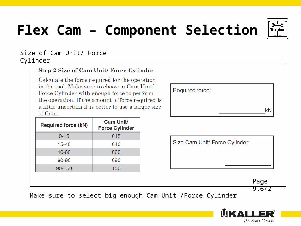
Page 9.6/2
Make sure to select big enough Cam Unit /Force Cylinder
Size of Cam Unit/ Force Cylinder

Flex Cam – Component Selection
Page 9.6/2
When a shorter stroke length is needed, arrange a mechanical stop in the die(contact your distributor for further support depending on your needs).
Stroke of Cam Unit/ Force Cylinder

Flex Cam – Component Selection
Page 9.6/3
Order number for the Cam Unit / Force Cylinder

Flex Cam – Component Selection
Page 9.6/4Three Power Unit options (a, b, c) different used stroke (110, 50 and 35) and ratio (0.5, 1.2, 2.0). Avoid the grey area, the ratio between press and cam unit is very high.
Size and Stroke of Power Unit
2
3a 3b 3c No No
1Used stroke
Flex Cam – Component Selection
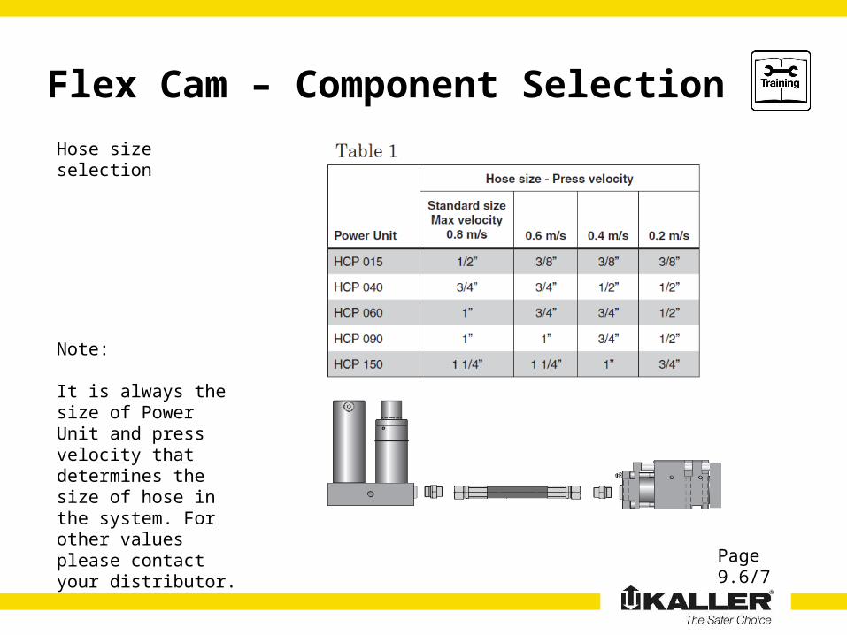
Page 9.6/7
Note:
It is always the size of Power Unit and press velocity that determines the size of hose in the system. For other values please contact your distributor.
Hose size selection

Flex Cam – Component Selection
Note:
Other values may be accepted under special conditions, contact your distributor
Capacity andPerformace
Page 9.7/1
Normal gas filling pressures

Flex Cam – Component Selection
Page 9.7/2
Note:
Min accumulator pressure 50 bar, max 180 bar.Normal pressure is 150 bar.
Accumulator pressure

Flex Cam – Component Dimensions
Page 9.8/1 – 47
Note:
See www.kaller.com for your 3D models.All is available including the hose system.

Flex Cam – Component Selection
Designing your Hose System
1. Hose size, check Power Unit size. See table 1 below. The hose has always straight ends.
2. Select adapters depending on connection threads and hose size. If possible, use straight adapters into the Power Units or Cam Units. If space problems, an Adjustable Locknut Elbow is available. See picture below.
3. Always use Hose Clamps when possible to avoid steel – hose contact especially sharp edges.
Page 9.8/37 – 49
Flex Cam – Component Selection
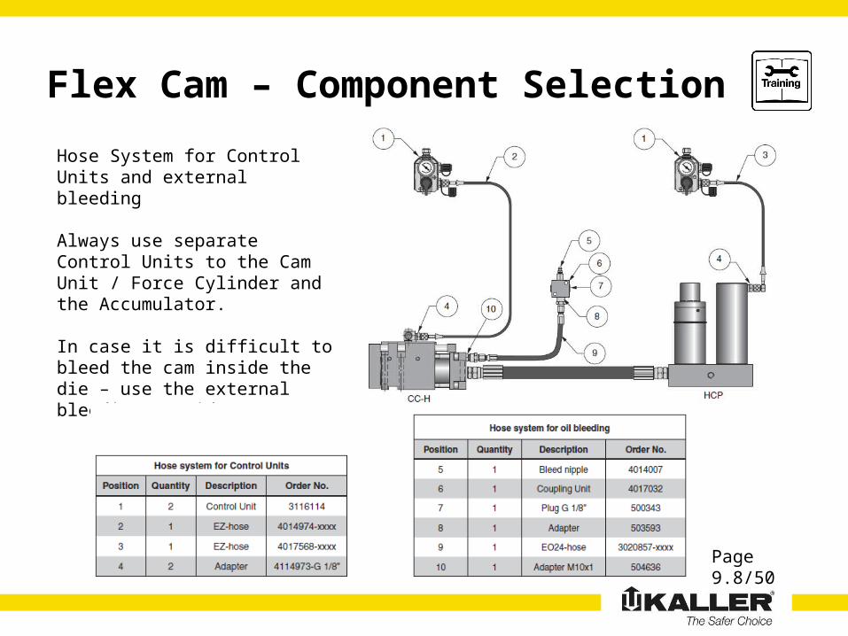
Page 9.8/50
Hose System for Control Units and external bleeding
Always use separate Control Units to the Cam Unit / Force Cylinder and the Accumulator.
In case it is difficult to bleed the cam inside the die – use the external bleeding outside

Flex Cam – Component Selection
Page 9.8/51
Hose System for Control Units and external bleeding
Only one control block can be used for both Cam Units – getting the same return force
But the external bleeding should be one for each Cam Unit – easier to bleed
Flex Cam – Component Selection
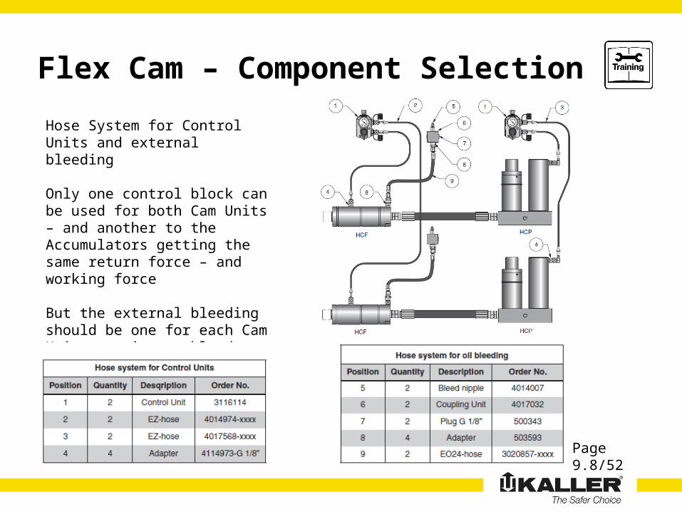
Page 9.8/52
Hose System for Control Units and external bleeding
Only one control block can be used for both Cam Units – and another to the Accumulators getting the same return force – and working force
But the external bleeding should be one for each Cam Unit – easier to bleed
Flex Cam – Component Selection
Page 9.8/53
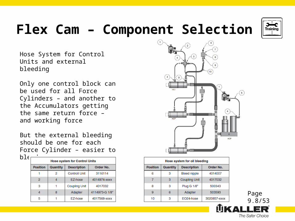
Hose System for Control Units and external bleeding
Only one control block can be used for all Force Cylinders – and another to the Accumulators getting the same return force – and working force
But the external bleeding should be one for each Force Cylinder – easier to bleed

Flex Cam – Installing the System
Page 9.9/1 – 2
• Use well educated personnel
• A clean working place to avoid contamination in system
• Functional equipment and tools
• Proper eye and skin protection
• Keep protection plugs on hoses, remove only when connect
• Handle nitrogen products with care (see gas spring guides)
• See recommended torque settings for screws (12.9 grade)
System installation

Flex Cam – Installing the System
Page 9.10/1
• A driver (1) is used to push the Piston Rod of Power Unit
• The Power Unit can be installed up-side down
• In case no room for standard HCP, use the HCP-S with
separate accumulator
• The Accumulator should always be used in the system
• Make sure to avoid side-load and over-stroke, see below
Power Unit installation
or

Flex Cam – Installing the System
Page 9.10/2
• Use dowel pins and key to locate the unit
• Punch plate (1) can be removed for machining
by remove screws (2). Note the Gas Spring (4).
• Force generated from punch should be within a
specified area (3), see catalogue for additional info.
• Minimize the angle on top of punch to avoid side-
load (above 5-7 degrees there is a risk of punch
sliding onto the panel surface).
• The Pump Unit can be used for final punch
adjustments by moving the cam forward and back.
Check the punch and die clearance.
Compact Cam installation
Flex Cam – Installing the System
Page 9.10/2
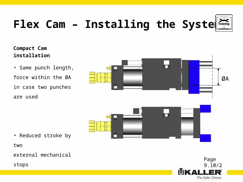
• Same punch length,
force within the ØA in case
two punches are used
• Reduced stroke by two
external mechanical stops
Compact Cam installation
ØA
Flex Cam – Installing the System
Page 9.10/2
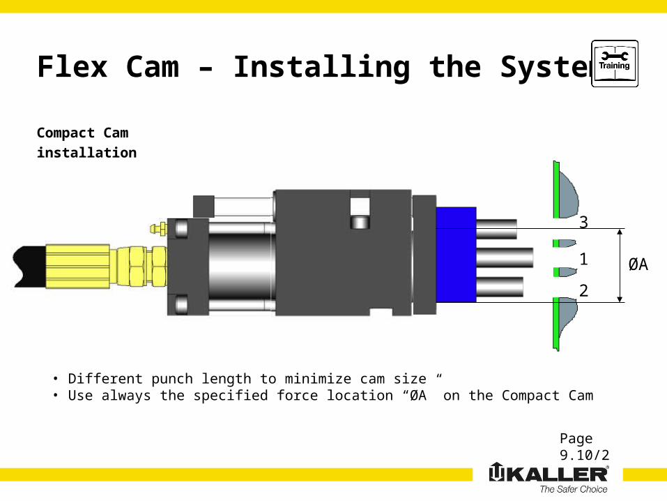
Compact Cam installation
ØA1
2
3
• Different punch length to minimize cam size• Use always the specified force location “ØA” on the Compact Cam

Flex Cam – Installing the System
Source: International conference Tool & die Volvo Oct. 5-6, 2004
Page 9.10/2

Flex Cam – Installing the System
Page 9.10/2Source: International conference Tool & die Volvo Oct. 5-6, 2004
Flex Cam – Installing the System
Page 9.10/2
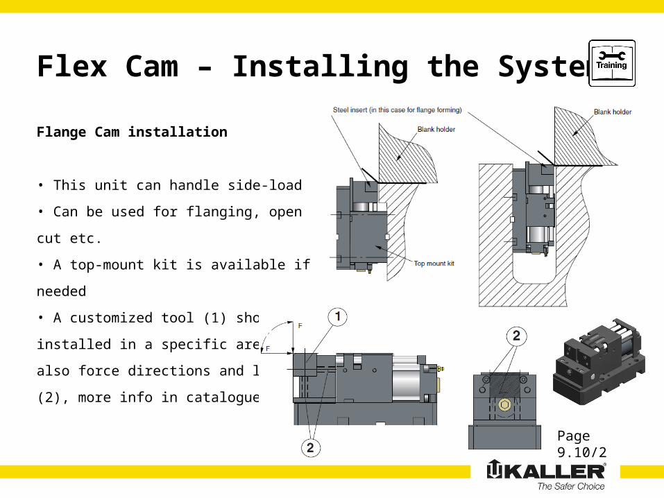
• This unit can handle side-load
• Can be used for flanging, open cut etc.
• A top-mount kit is available if needed
• A customized tool (1) should be installed in
a specific area, see also force directions and
location (2), more info in catalogue
Flange Cam installation

Flex Cam – Installing the System
Page 9.10/3
• To be used to push guided tool parts
• To return the tool part, separate gas springs is
recommended if possible (even if the rod has
threaded holes in case this is needed)
• Flange, foot or base mount is available
• Make sure no side load on the rod
• Use mechanical return stops in the tool to avoid
heavy load (weight) on the actual cylinder
• For flange mount, use max 0.5 mm clearance as
the picture. All three C-grooves can be used for the
flange. See also the Key support for foot mount
Force Cylinder installation

Flex Cam – Installing the System
Page 9.10/3
• The hoses are washed and plugged, keep the plugs on
as long as possible
• Make sure no contact hose – sharp edges by using hose
clamps (3). Hoses move a little when running
• Adjustable adapters has an o-ring (3) and a steel support
ring (4) to be used
• Do not twist the hose or use a too short hose
• Tighten the hose and adapters until you feel a firmly stop
Hose installation

Flex Cam – Fill and Bleed
Page 9.11/1-5
• Pump Unit 3017075
• Hook Spanner (-015) 503417
• Hook Spanner (-040-150) 503418
• Allen Key 6 mm
• Open-ended or ring spanner 11 mm
• Open-ended or ring spanner 14 mm
• 18 litres of oil ISO VG 32 (see 9.7/1)
Fill and bleed, see ”Quick Start Guide”
Necessary tools and equipment:

Flex Cam – Fill and Bleed
Page 9.11/1-5
• Make sure there is room enough for accumulator in die
• Apply Nitrogen Gas / Initial Charge Settings below
using the same equipments as for gas springs
• In case self-contained gas springs are used for a
Compact Cam – no need to fill gas
• Accumulator must be filled later with higher pressure
Fill and bleed, see ”Quick Start Guide”

Flex Cam – Fill and Bleed
Page 9.11/2Fill oil in the pump (max 18 litres) and connect the pump unit as shown above

Flex Cam – Fill and Bleed
Page 9.11/4
Run Pump
Manometer
Valve/ Hose B
Knob C
(operates check valve in position)
Valve/ Hose A
• Check tool
clearance before
moving the cam unit
• Check punch
alignment etc. when
moving the cam unit
Flex Cam – Production running
Page 9.10/3
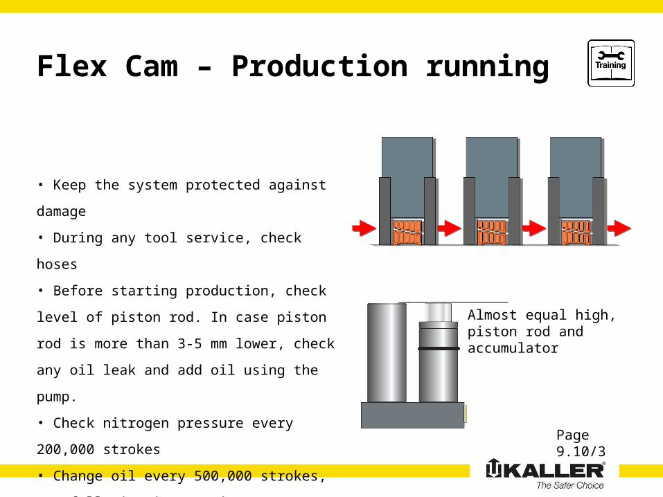
• Keep the system protected against damage
• During any tool service, check hoses
• Before starting production, check level of
piston rod. In case piston rod is more than 3-5
mm lower, check any oil leak and add oil using
the pump.
• Check nitrogen pressure every 200,000
strokes
• Change oil every 500,000 strokes, see
following instructions
Almost equal high, piston rod and accumulator

Flex Cam – Production running
Page 9.11/5
• Change oil after 500,000 strokes
• Open valve A, pump oil until clean oil comes out
• Close valve A, dispose of waste oil appropriately
• Make sure oil pressure is 0 bar
• Ready to use again

Flex Cam – Training
• Understand the concept
• Find the information
• Select Components
• Install the system
• Fill & bleed
• Get the production running
Training…
Is about safety and to…
The Product Presentation with all applications, this Training Presentation, FlexCam catalogue, Quick Start Guide and User´s Guide to be used – from process engineers, purchase dep., die designers, die makers to end users include maintenance
Catalogue page