flexi wcdma bts system module description
TRANSCRIPT

Flexi WCDMA BTS System ModuleDescription
DN7084495Issue 7-3 en30/04/2009
# Nokia Siemens Networks 1 (51)
Nokia Siemens Networks WCDMA RAN, Rel.RU10, System Library, v. 2

The information in this document is subject to change without notice and describes only theproduct defined in the introduction of this documentation. This documentation is intended for theuse of Nokia Siemens Networks customers only for the purposes of the agreement under whichthe document is submitted, and no part of it may be used, reproduced, modified or transmitted inany form or means without the prior written permission of Nokia Siemens Networks. Thedocumentation has been prepared to be used by professional and properly trained personnel,and the customer assumes full responsibility when using it. Nokia Siemens Networks welcomescustomer comments as part of the process of continuous development and improvement of thedocumentation.
The information or statements given in this documentation concerning the suitability, capacity, orperformance of the mentioned hardware or software products are given “as is” and all liabilityarising in connection with such hardware or software products shall be defined conclusively andfinally in a separate agreement between Nokia Siemens Networks and the customer. However,Nokia Siemens Networks has made all reasonable efforts to ensure that the instructionscontained in the document are adequate and free of material errors and omissions. NokiaSiemens Networks will, if deemed necessary by Nokia Siemens Networks, explain issues whichmay not be covered by the document.
Nokia Siemens Networks will correct errors in this documentation as soon as possible. IN NOEVENT WILL NOKIA SIEMENS NETWORKS BE LIABLE FOR ERRORS IN THISDOCUMENTATION OR FOR ANY DAMAGES, INCLUDING BUT NOT LIMITED TO SPECIAL,DIRECT, INDIRECT, INCIDENTAL OR CONSEQUENTIAL OR ANY LOSSES, SUCH AS BUTNOT LIMITED TO LOSS OF PROFIT, REVENUE, BUSINESS INTERRUPTION, BUSINESSOPPORTUNITY OR DATA, THAT MAYARISE FROM THE USE OF THIS DOCUMENT OR THEINFORMATION IN IT.
This documentation and the product it describes are considered protected by copyrights andother intellectual property rights according to the applicable laws.
The wave logo is a trademark of Nokia Siemens Networks Oy. Nokia is a registered trademark ofNokia Corporation. Siemens is a registered trademark of Siemens AG.
Other product names mentioned in this document may be trademarks of their respective owners,and they are mentioned for identification purposes only.
Copyright © Nokia Siemens Networks 2009. All rights reserved.
2 (51) # Nokia Siemens Networks DN7084495Issue 7-3 en30/04/2009
Flexi WCDMA BTS System Module Description

Contents
Contents 3
Summary of changes 5
1 System Module operation and main blocks 71.1 Operation 71.2 Functional blocks 10
2 Power requirements of the System Module and transmission sub-modules 19
2.1 Power requirements of the System Module 192.2 Power requirements of transmission sub-modules 202.3 FPFA and FPFB interfaces 212.4 FPFA electrical connections 25
3 System Module dimensions and weights 27
4 System Module interfaces 29
5 System Module LED indications 35
6 System Module as an extension module 39
Appendix A System Module connector pin maps 41A.1 External synchronization input interface connector pin map 41A.2 External synchronisation output interface connector pin map 42A.3 Power supply RF Module 1-3 and BB-extension connectors pin map 44A.4 10/100 Eth LMP connector pin map 45A.5 10/100 Eth FPMA connector pin map 46A.6 10/100 Eth OVP connector pin map 47A.7 10/100/1000 Eth ETP connector pin map 48A.8 EAC connector pin map 49A.9 DC input connector pin map 50A.10 Grounding connector pin map 51
DN7084495Issue 7-3 en30/04/2009
# Nokia Siemens Networks 3 (51)
Contents
4 (51) # Nokia Siemens Networks DN7084495Issue 7-3 en30/04/2009
Flexi WCDMA BTS System Module Description

Summary of changes
Changes between document issues are cumulative. Therefore, the latestdocument issue contains all changes made to previous issues.
Changes between issues 7-2 and 7-3
Sections RJ-48C connector pin maps and FTHA interface pin mapsmoved to Flexi WCDMA BTS Transmission Description.
Changes between issues 7-1 and 7-2
FSMC and FSMD power consumption tables in section System Modulepower requirements edited.
Section FPFA and FPFB interfaces edited. Figure FPFB interfacesupdated and figure Bottom view of the FPFB removed.
Section System Module dimensions and weights updated.
Outdoor transmission cable information moved to the Cabling FlexiWCDMA BTS and Creating Configurations document.
Information related to Flexi System External GPS Mediator (FSEG)removed from table System Module connectors in section System Moduleinterfaces. LEDs in figure Front panel of the System module (FSMB)corrected.
System Module connector pin maps moved to Appendix.
Table External synchronization input interface connector (MDR26) insection External synchronization input interface connector pin mapupdated.
Table Power supply RF Module 1-3 and BB-extension connectors (4 Xmulti-beam) in section Power supply RF Module 1-3 and BB-extensionconnectors pin map updated.
DN7084495Issue 7-3 en30/04/2009
# Nokia Siemens Networks 5 (51)
Summary of changes
Table DC input connector (Terminal block) in section DC input connectorpin map updated.
Table Grounding connector (screw terminal) in section Groundingconnector pin map updated.
Editorial changes made.
Changes between issues 7-0 and 7-1
Editorial changes made.
6 (51) # Nokia Siemens Networks DN7084495Issue 7-3 en30/04/2009
Flexi WCDMA BTS System Module Description

1 System Module operation and mainblocks
1.1 Operation
The Flexi System Module hosts the telecom control, system operation andmaintenance, baseband application, transmission, and power distributionfunctionality. The System Module can also act as a System ExtensionModule operating in a baseband extension mode.
The following versions of the System Module are available:
. System Module FSMB (rel. 1)
. System Module FSMC (rel. 2)
. System Module FSMD (rel. 2)
System Module rel. 2 has increased control and baseband processingcapacity compared to System Module rel. 1. Furthermore, System Modulerel. 2 can act as an extension to System Module rel. 1 (but not vice versa).
The System Module provides the following BTS external interfaces:
. BTS Site Element Manager
. transmission interfaces
. three external interfaces towards RF
. site support system interface (for example, battery back-up)
. auxiliarity interface (customer-specific Ethernet port with overvoltageprotection)
. auxiliarity interface Ethernet for future expansions
. external alarms and controls interface (customer-specific alarms)
DN7084495Issue 7-3 en30/04/2009
# Nokia Siemens Networks 7 (51)
System Module operation and main blocks

. external synchronisation input interface
. external synchronisation output interface
. baseband extension interface
The System Module has an integrated BTS clock that distributes thesynchronisation clocks to other BTS modules. The System Modulehardware is HSDPA and HSUPA compliant.
The System Module uses nominal -48 V DC and distributes it on to RF andSystem Extension Modules. The System Module includes integrated fans.
The System Module can be used, for example, for the following softwarefunctionalities:
. BTS level O&M processing (BTSOM)
. resource management
. node B server
. NBAP handler
. user plane management
See the following figure for an exploded view of the System Module.
8 (51) # Nokia Siemens Networks DN7084495Issue 7-3 en30/04/2009
Flexi WCDMA BTS System Module Description
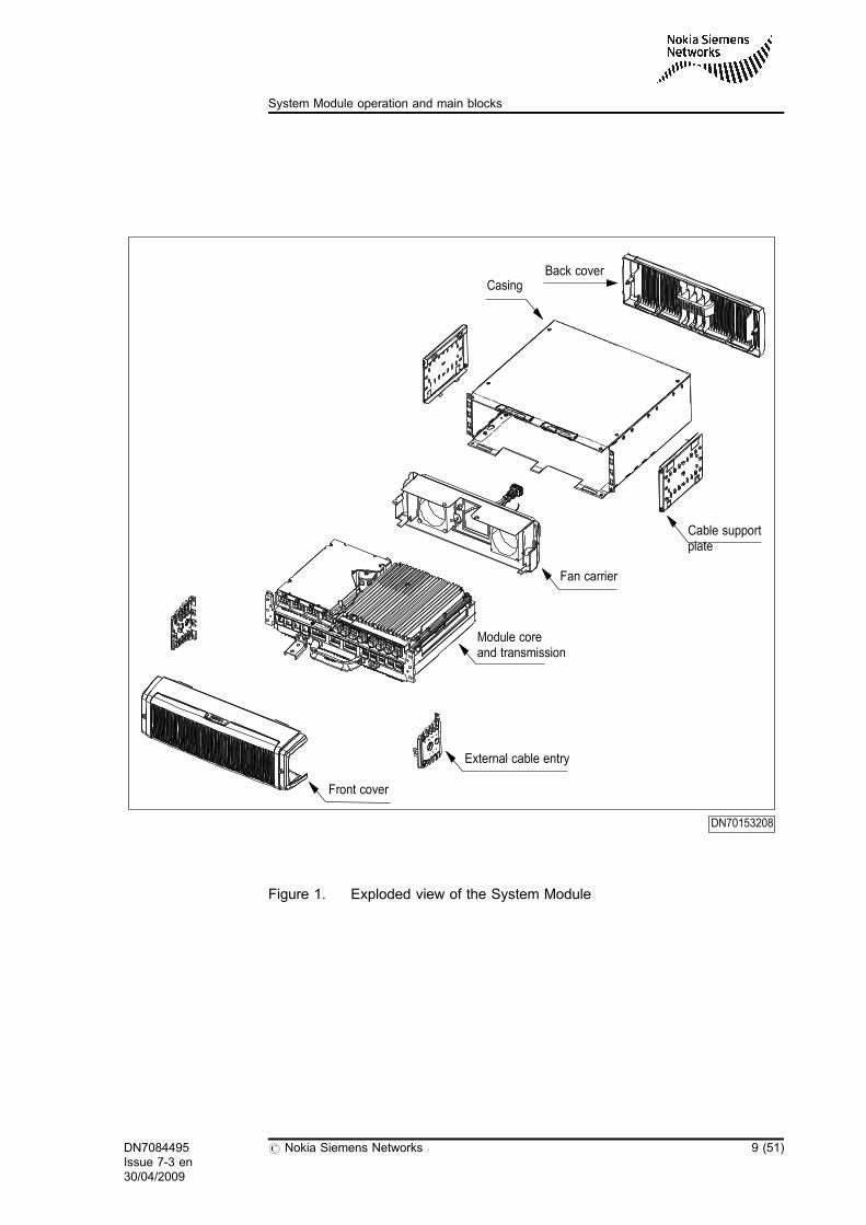
Figure 1. Exploded view of the System Module
DN70153208
Front cover
External cable entry
Cable supportplate
Casing
Fan carrier
Back cover
Module coreand transmission
DN7084495Issue 7-3 en30/04/2009
# Nokia Siemens Networks 9 (51)
System Module operation and main blocks

Figure 2. Type label location of the System Module
1.2 Functional blocks
See the following figures for the functional blocks of the System Module.
DN70351805
Type Label
10 (51) # Nokia Siemens Networks DN7084495Issue 7-3 en30/04/2009
Flexi WCDMA BTS System Module Description

Figure 3. Functional blocks of the System Module (FSMB)
Ext IFblock
Fan Fan Moduleheater
Tempsensors
Control blockand
Timing block
BBprocessing
block
PowerDistribution
block
Transmissionsub-module
(FTxx)
BB ExtensionIF blocks
ControlClockRP1’+RP2’ DataRP3’ Data
Legend:
-48 V DC
TransmissionIF
-48 V DC,48RTN
Ext IF
OPT RF1
OPT EXT 1
BBprocessing
block
BBprocessing
block
RF IF block
RP3 Bus Multiplexing &Summing and
Ethernet switching
OPT RF2
OPT RF3
OPT EXT 2
DN7082531
DN7084495Issue 7-3 en30/04/2009
# Nokia Siemens Networks 11 (51)
System Module operation and main blocks

Figure 4. Functional blocks of the System Module (FSMC/D)
Flexi WCDMA BTS control and multiplexing
This functionality is responsible for BTS control and management, systemclock generation and distribution to other modules and sub-modules. Thefunctional distribution of this functionality is as follows:
Ext IFblock
Fan Fan Moduleheater
Tempsensors
Control blockand
Timing block
PowerDistribution
block
Transmissionsub-module
(FTxx)
BB ExtensionIF blocks
ControlClockRP1’+RP2’ DataRP3’ Data
Legend:
-48 V DC
TransmissionIF
-48 V DC,48RTN
Ext IF
OPT RF1
OPT EXT 1
BBprocessing
block
BBprocessing
block(FSMD only)
RF IF block
RP3 Bus Multiplexing &Summing and
Ethernet switching
OPT RF2
OPT RF3
OPT EXT 2
DN70546962
12 (51) # Nokia Siemens Networks DN7084495Issue 7-3 en30/04/2009
Flexi WCDMA BTS System Module Description
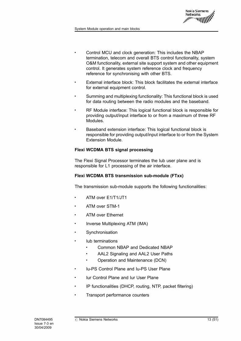
. Control MCU and clock generation: This includes the NBAPtermination, telecom and overall BTS control functionality, systemO&M functionality, external site support system and other equipmentcontrol. It generates system reference clock and frequencyreference for synchronising with other BTS.
. External interface block: This block facilitates the external interfacefor external equipment control.
. Summing and multiplexing functionality: This functional block is usedfor data routing between the radio modules and the baseband.
. RF Module interface: This logical functional block is responsible forproviding output/input interface to or from a maximum of three RFModules.
. Baseband extension interface: This logical functional block isresponsible for providing output/input interface to or from the SystemExtension Module.
Flexi WCDMA BTS signal processing
The Flexi Signal Processor terminates the Iub user plane and isresponsible for L1 processing of the air interface.
Flexi WCDMA BTS transmission sub-module (FTxx)
The transmission sub-module supports the following functionalities:
. ATM over E1/T1/JT1
. ATM over STM-1
. ATM over Ethernet
. Inverse Multiplexing ATM (IMA)
. Synchronisation
. Iub terminations. Common NBAP and Dedicated NBAP. AAL2 Signaling and AAL2 User Paths. Operation and Maintenance (DCN)
. Iu-PS Control Plane and Iu-PS User Plane
. Iur Control Plane and Iur User Plane
. IP functionalities (DHCP, routing, NTP, packet filtering)
. Transport performance counters
DN7084495Issue 7-3 en30/04/2009
# Nokia Siemens Networks 13 (51)
System Module operation and main blocks
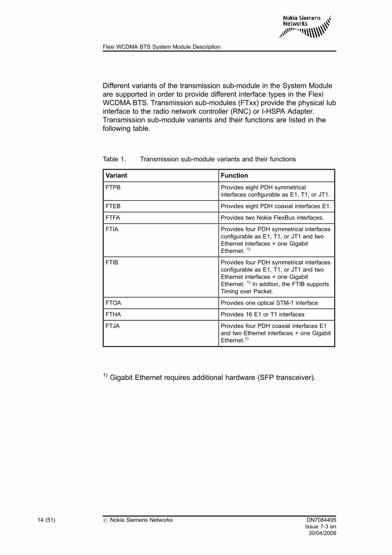
Different variants of the transmission sub-module in the System Moduleare supported in order to provide different interface types in the FlexiWCDMA BTS. Transmission sub-modules (FTxx) provide the physical Iubinterface to the radio network controller (RNC) or I-HSPA Adapter.Transmission sub-module variants and their functions are listed in thefollowing table.
Table 1. Transmission sub-module variants and their functions
Variant Function
FTPB Provides eight PDH symmetricalinterfaces configurable as E1, T1, or JT1.
FTEB Provides eight PDH coaxial interfaces E1.
FTFA Provides two Nokia FlexBus interfaces.
FTIA Provides four PDH symmetrical interfacesconfigurable as E1, T1, or JT1 and twoEthernet interfaces + one GigabitEthernet. 1)
FTIB Provides four PDH symmetrical interfacesconfigurable as E1, T1, or JT1 and twoEthernet interfaces + one GigabitEthernet. 1) In addtion, the FTIB supportsTiming over Packet.
FTOA Provides one optical STM-1 interface
FTHA Provides 16 E1 or T1 interfaces
FTJA Provides four PDH coaxial interfaces E1and two Ethernet interfaces + one GigabitEthernet.1)
1) Gigabit Ethernet requires additional hardware (SFP transceiver).
14 (51) # Nokia Siemens Networks DN7084495Issue 7-3 en30/04/2009
Flexi WCDMA BTS System Module Description

Figure 5. Transmission sub-module FTPB
Figure 6. Transmission sub-module FTEB
DN70148552
DN70148588
DN7084495Issue 7-3 en30/04/2009
# Nokia Siemens Networks 15 (51)
System Module operation and main blocks

Figure 7. Transmission sub-module FTFA
Figure 8. Transmission sub-module FTIA and FTIB
DN70148576
DN70148564
16 (51) # Nokia Siemens Networks DN7084495Issue 7-3 en30/04/2009
Flexi WCDMA BTS System Module Description

Figure 9. Transmission sub-module FTOA
Figure 10. Transmission sub-module FTHA
DN70245378
DN7084495Issue 7-3 en30/04/2009
# Nokia Siemens Networks 17 (51)
System Module operation and main blocks

Figure 11. Transmission sub-module FTJA
DN70348735
18 (51) # Nokia Siemens Networks DN7084495Issue 7-3 en30/04/2009
Flexi WCDMA BTS System Module Description

2 Power requirements of the SystemModule and transmission sub-modules
2.1 Power requirements of the System Module
The power supply of the System Module is described in the tables below.The same power consumption figures also apply for the System ExtensionModule.
Table 2. Input voltage of the System Module
Property Value
Nominal supply voltage -48.0 V DC
Input voltage range 40.5 - 57.0 V DC
Table 3. Power consumption of the FSMB (not including transmission and RFModules supplied from the FPFA/B) and System Extension Module
Property Value
Max. 170 W*
Typical 106 W**
Min. 90 W**
DN7084495Issue 7-3 en30/04/2009
# Nokia Siemens Networks 19 (51)
Power requirements of the System Module and transmission sub-modules

Table 4. Power consumption of the FSMC (not including transmission) andSystem Extension Module
Property Value
Max. 175 W*
Typical 85 W**
Min. 73 W***
Table 5. Power consumption of the FSMD (not including transmission) andSystem Extension Module
Property Value
Max. 250 W*
Typical 150 W**
Min. 126 W***
* During cold start-up (module heater on, high load)
** Operational power consumption at room temperature
*** Module in idle state, fans off, +0°C
All above with nominal 48V voltage input.
For the fuse ratings of the FPFA/B outputs, see section FPFA and FPFBinterfaces below.
For transmission sub-module power consumption figures, see sectionPower requirements of transmission sub-modules.
2.2 Power requirements of transmission sub-modules
The typical power consumption of the transmission sub-modules isdescribed in the table below.
20 (51) # Nokia Siemens Networks DN7084495Issue 7-3 en30/04/2009
Flexi WCDMA BTS System Module Description

Table 6. Power consumption of the transmission sub-modules
Variant Typical power consumption [W]
FTPB 22.3 W
FTEB 22.3 W
FTFA 89.7 W
FTIA 22.8 W
FTIB 20.2 W
FTHA 18.5 W
FTJA 22.8 W
FTOA 22.8 W
Power consumption depends on the equipment connected to the FTFAsub-module.
2.3 FPFA and FPFB interfaces
Power is distributed from Flexi Power Distribution and Fuses (FPFA andFPFB) to the System Module. The FPFA is used with System Module rel.1, whereas in System Module rel. 2 it is replaced with the FPFB, whichgives more power feeding capacity to RF Modules. The FPFB iscompatible with both System Module releases.
The FPFB does not have any circuit breakers but instead electrical fusesand a dedicated power switch for the System Module. The fuse rates forthe FPFA are:
. A.101: RF1-3 20.0A, EXT 25.0A
. A.102 or later: RF1-3 20.0A, EXT 25.0A (System Module suppliedvia EXT circuit breaker)
The fuse rates for the FPFB are:
. RF1-3 31.0A (+/-2A), EXT 25.0A (+/- 4.5A)
See the following figure for the location of the FPFA/B.
DN7084495Issue 7-3 en30/04/2009
# Nokia Siemens Networks 21 (51)
Power requirements of the System Module and transmission sub-modules

Figure 12. Location of the FPFA/B in the System Module
Inputs and outputs
A busbar input connector (with screw connection) must always be used forinput connections of the FPFA/B and when connecting power to theSystem Extension Module.
The multibeam connectors on the front panel must not be used as input tothe FPFA/B. The multibeam connectors are not hot-plug connectors. Thepower must be switched off via the on/off switch on the FPFA/B front panelwhen connecting or disconnecting the RF or System Extension Module tothe FPFA/B.
There are two types of FPFAs available:
. A101 version
. A102, A103 or later
There are differences between these versions in the inner connections.
DN70424873
FPFA/B
Type Label
22 (51) # Nokia Siemens Networks DN7084495Issue 7-3 en30/04/2009
Flexi WCDMA BTS System Module Description

Figure 13. FPFA interfaces
The above figure illustrates FPFA version A.102 or later. System Modulecore version is indicated on the bar code label together with the serialnumber, whereas the FPFA version information is available on the FPFAbar code label attached on top of the FPFA.
RF1 RF3RF2 EXT Connector to System Module(located on the bottom)
DC input connector forSystem Module andExtension Module
DN70322858
Extension Module/System Module
Circuitbreakers: RF1 RF2 RF3
LEDRF1
LEDRF2
LEDEXT
LEDRF3
DN7084495Issue 7-3 en30/04/2009
# Nokia Siemens Networks 23 (51)
Power requirements of the System Module and transmission sub-modules

Figure 14. FPFB interfaces
There are five membrane switches on the FPFB front panel for the outputs.The switches control power control circuits and have two states: On andStand-by.
FPFA LED indications for RF1, RF2, RF3 and EXT
The four LEDs on the FPFA front panel indicate the state of the circuitbreakers (CB) if load (for example the RF Module or the System ExtensionModule) is connected to FPFA output. When lit, the LED is red.
LED on:
. Load connected to FPFA output and CB has tripped
. Load connected to FPFA output and CB switch pulled to off position
LED off:
. Load not connected at all
. Load connected to FPFA output and the power supply is on (CB hasnot tripped)
DN70547128
RF1LED
DC input connector forSystem Module andExtension Module
RF2LED
SMLED
RF3LED
EXTLED
membraneswitches:
SM
RF 3EXT
RF 2
RF 1Connector to
System Module(located on the bottom)
RF 1RF 2
RF 3 EXT
24 (51) # Nokia Siemens Networks DN7084495Issue 7-3 en30/04/2009
Flexi WCDMA BTS System Module Description

FPFB LED indications for RF1, RF2, SM, RF3 and EXT
The FPFB has five tricolour LEDs on the FPFB front panel for outputs'status indication.
LED colour Indication
Yellow Stand-by, output disabled
Green Normal operation, output enabled
Red Fault, output disabled
Yellow, blinking Remote controlled, output disabled
2.4 FPFA electrical connections
Note that there is a risk of short circuit. Connect the power cable asinstructed.
FPFA version A101
Extension module power supply comes through the circuit breaker andextension module power can be switched off via the circuit breaker. Thismust be done if the extension module is connected to the System Moduleto avoid hot-plug connection. This also required when disconnecting fromthe System Module.
When pulling the EXT circuit breaker switch to off position, switch off thepower supply to the extension module. Power feed to the System Moduleis still on.
FPFA version A102, A103 or later
FPFA versions A102, A103 or later have a common power supply via thesame circuit breaker for the System Module and the System ExtensionModule. This means that the same circuit breaker switch can be used toswitch on and off the power to the System Module and the SystemExtension Module.
Note
The System Module and extension modules are reset by pulling theEXT circuit breaker on/off switch on the front panel.
DN7084495Issue 7-3 en30/04/2009
# Nokia Siemens Networks 25 (51)
Power requirements of the System Module and transmission sub-modules
When connecting the extension module to the System Module, switch offthe circuit breaker to avoid hot-plug connection to extension modules.After that, switch off the System Module.
This is also required when disconnecting the extension module from theSystem Module.
26 (51) # Nokia Siemens Networks DN7084495Issue 7-3 en30/04/2009
Flexi WCDMA BTS System Module Description
3 System Module dimensions and weights
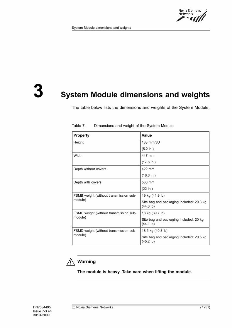
The table below lists the dimensions and weights of the System Module.
Table 7. Dimensions and weight of the System Module
Property Value
Height 133 mm/3U
(5.2 in.)
Width 447 mm
(17.6 in.)
Depth without covers 422 mm
(16.6 in.)
Depth with covers 560 mm
(22 in.)
FSMB weight (without transmission sub-module)
19 kg (41.9 lb)
Site bag and packaging included: 20.3 kg(44.8 lb)
FSMC weight (without transmission sub-module)
18 kg (39.7 lb)
Site bag and packaging included: 20 kg(44.1 lb)
FSMD weight (without transmission sub-module)
18.5 kg (40.8 lb)
Site bag and packaging included: 20.5 kg(45.2 lb)
Warning
The module is heavy. Take care when lifting the module.
DN7084495Issue 7-3 en30/04/2009
# Nokia Siemens Networks 27 (51)
System Module dimensions and weights
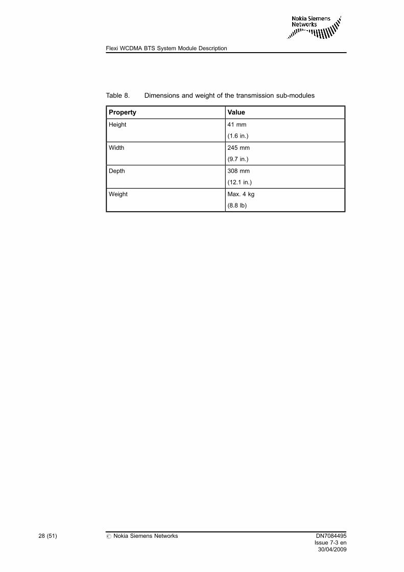
Table 8. Dimensions and weight of the transmission sub-modules
Property Value
Height 41 mm
(1.6 in.)
Width 245 mm
(9.7 in.)
Depth 308 mm
(12.1 in.)
Weight Max. 4 kg
(8.8 lb)
28 (51) # Nokia Siemens Networks DN7084495Issue 7-3 en30/04/2009
Flexi WCDMA BTS System Module Description

4 System Module interfaces
The System Module is equipped with the following interfaces:
. Front panel connectors
. DC input connector (in the centre of the module)
The System Module has 24 connectors on the module. The connectors,their types and purposes are listed in the table below. The System Moduleis connected to the System Extension Module with a DC cable and twooptical cables.
Table 9. System Module connectors
Connector Type Purpose
Power supply RF Module 1 Multi-beam XL power supplyconnector
Power delivery to RF1
Power supply RF Module 2 Multi-beam XL power supplyconnector
Power delivery to RF2
Power supply RF Module 3 Multi-beam XL power supplyconnector
Power delivery to RF3.Recommended for I-HSPAuse.
Power supply BB-EXT Module Multi-beam XL power supplyconnector
Power delivery to SystemExtension Module operatingin BB-ext mode. Can be usedfor I-HSPA.
Transmission interfaces 8 x RJ-48/16 x SMB/2 x TNC/1 xduplex LC connector
2 x RJ-45 connector
1x GE via SFP transceiver
Variable transmissioninterfaces
FSMB: 10/100 Eth
FSMC/D: 10/100/1000 Eth
RJ-45 connector For local management tool
DN7084495Issue 7-3 en30/04/2009
# Nokia Siemens Networks 29 (51)
System Module interfaces
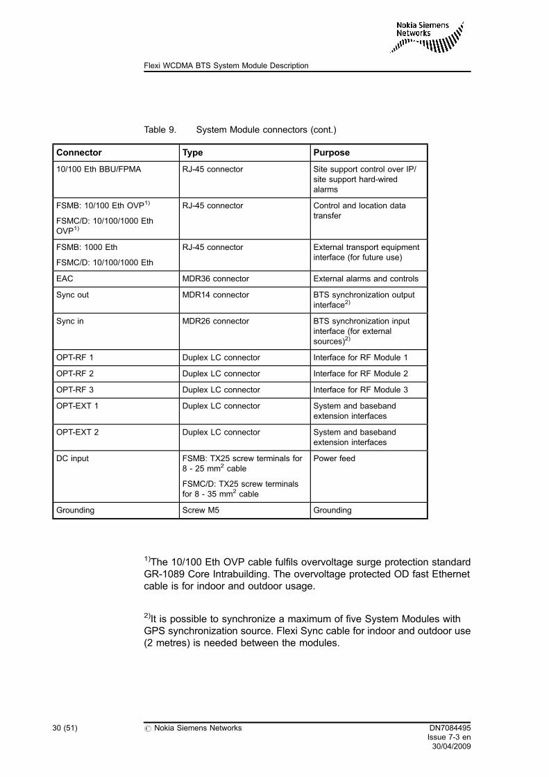
Table 9. System Module connectors (cont.)
Connector Type Purpose
10/100 Eth BBU/FPMA RJ-45 connector Site support control over IP/site support hard-wiredalarms
FSMB: 10/100 Eth OVP1)
FSMC/D: 10/100/1000 EthOVP1)
RJ-45 connector Control and location datatransfer
FSMB: 1000 Eth
FSMC/D: 10/100/1000 Eth
RJ-45 connector External transport equipmentinterface (for future use)
EAC MDR36 connector External alarms and controls
Sync out MDR14 connector BTS synchronization outputinterface2)
Sync in MDR26 connector BTS synchronization inputinterface (for externalsources)2)
OPT-RF 1 Duplex LC connector Interface for RF Module 1
OPT-RF 2 Duplex LC connector Interface for RF Module 2
OPT-RF 3 Duplex LC connector Interface for RF Module 3
OPT-EXT 1 Duplex LC connector System and basebandextension interfaces
OPT-EXT 2 Duplex LC connector System and basebandextension interfaces
DC input FSMB: TX25 screw terminals for8 - 25 mm2 cable
FSMC/D: TX25 screw terminalsfor 8 - 35 mm2 cable
Power feed
Grounding Screw M5 Grounding
1)The 10/100 Eth OVP cable fulfils overvoltage surge protection standardGR-1089 Core Intrabuilding. The overvoltage protected OD fast Ethernetcable is for indoor and outdoor usage.
2)It is possible to synchronize a maximum of five System Modules withGPS synchronization source. Flexi Sync cable for indoor and outdoor use(2 metres) is needed between the modules.
30 (51) # Nokia Siemens Networks DN7084495Issue 7-3 en30/04/2009
Flexi WCDMA BTS System Module Description

For lightning surge requirements, see section Lightning surgerequirements in the Flexi WCDMA BTS Installation Site Requirementsdocument.
The System Module front panel is illustrated in the following figures.
Figure 15. Front panel of the System Module (FSMB)
For the location of the LEDs, see section System Module LED indicationsin this document.
10/100 Eth
10/100 EthFPMA
10/100 EthOVP
1000 Eth
EACSyncIn
SyncOut
OPT-RF1
OPT-RF2
OPT-RF3
OPT-EXT1
OPT-EXT2
Power SupplyRF Module
1
Power SupplyRF Module
2
Power SupplyRF Module
3
Power SupplyBB-EXT Module
Grounding points
Circuit breakers
RF1 RF2 RF3
Transmissioninterfaces
LED LED LED LED
EXT
DN7080615
DN7084495Issue 7-3 en30/04/2009
# Nokia Siemens Networks 31 (51)
System Module interfaces

Figure 16. Front panel of the System Module (FSMC/D)
The location of the DC input connector is illustrated in the following figure.
DN70546686
10/100/1000Eth LMP
10/100 EthBBU/FPMA
10/100/1000Eth OVP
10/100/1000Eth ETP
EACSyncIn
SyncOut
OPT-RF1
OPT-RF2
OPT-RF3
OPT-EXT1
OPT-EXT2
Power SupplyRF Module 1
Power SupplyRF Module 2
Power SupplyRF Module 3
Power SupplyBB-EXT Module
Grounding points
LEDRF1
Transmissioninterfaces
LEDRF2
LEDRF3
LEDSM
LEDEXT
RF1 RF2 SM RF3 EXT
Membrane switches
32 (51) # Nokia Siemens Networks DN7084495Issue 7-3 en30/04/2009
Flexi WCDMA BTS System Module Description

Figure 17. DC input connector in the System Module
For System Module connector pin maps, see the following appendices:
. External synchronization input interface connector pin map
. External synchronisation output interface connector pin map
. Power supply RF Module 1-3 and BB-extension connectors pin map
. 10/100 Eth LMP connector pin map
. 10/100 Eth FPMA connector pin map
. 10/100 Eth OVP connector pin map
. 10/100/1000 Eth ETP connector pin map
. EAC connector pin map
. DC input connector pin map
. Grounding connector pin map
. RJ-48C connector pin maps
. FTHA interface pin maps
DN70150444
DC input connector
DN7084495Issue 7-3 en30/04/2009
# Nokia Siemens Networks 33 (51)
System Module interfaces

The following connectors are optical fibre connectors, and therefore, haveno pin maps.
. OPT-RF1
. OPT-RF2
. OPT-RF3
. OPT-EXT1
. OPT-EXT2
34 (51) # Nokia Siemens Networks DN7084495Issue 7-3 en30/04/2009
Flexi WCDMA BTS System Module Description

5 System Module LED indications
The System Module has seven tri-colour LEDs on the front panel toindicate the operational status of the module and all fault conditions duringoperation. See the following figure for the System Module LEDs.
Figure 18. System Module LED positions
The FPFA has four and the FPFB five additional LEDs on its front panel.See figure Front panel of the System Module (FSMB) for the location of theFPFA LEDs and figure Front panel of the System Module (FSMC/D) for thelocation of the FPFB LEDs in section System Module interfaces in thisdocument.
The LED indications of the System Module are listed and explained in thetable below.
FAN
SYSTEM MODULESTATUS
OPT-RF2 OPT-RF3
OPT-RF1 OPT-EXT1
OPT-EXT2
DN7084495Issue 7-3 en30/04/2009
# Nokia Siemens Networks 35 (51)
System Module LED indications
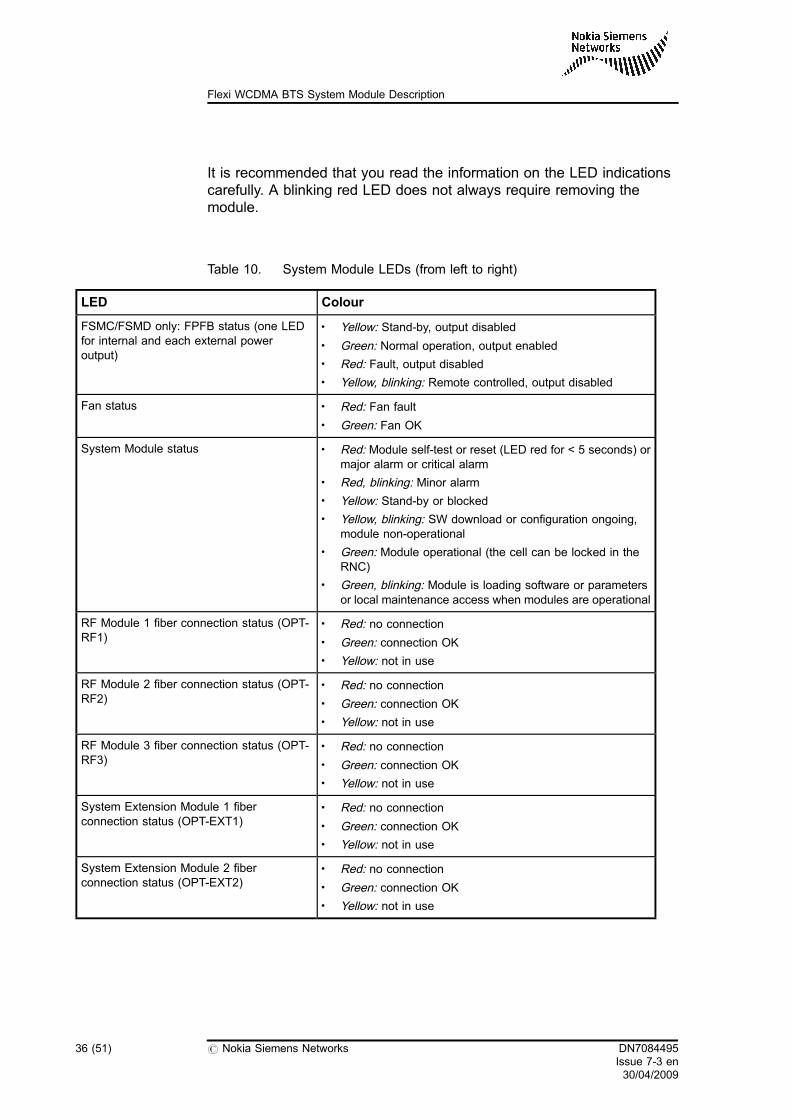
It is recommended that you read the information on the LED indicationscarefully. A blinking red LED does not always require removing themodule.
Table 10. System Module LEDs (from left to right)
LED Colour
FSMC/FSMD only: FPFB status (one LEDfor internal and each external poweroutput)
. Yellow: Stand-by, output disabled
. Green: Normal operation, output enabled
. Red: Fault, output disabled
. Yellow, blinking: Remote controlled, output disabled
Fan status . Red: Fan fault. Green: Fan OK
System Module status . Red: Module self-test or reset (LED red for < 5 seconds) ormajor alarm or critical alarm
. Red, blinking: Minor alarm
. Yellow: Stand-by or blocked
. Yellow, blinking: SW download or configuration ongoing,module non-operational
. Green: Module operational (the cell can be locked in theRNC)
. Green, blinking: Module is loading software or parametersor local maintenance access when modules are operational
RF Module 1 fiber connection status (OPT-RF1)
. Red: no connection
. Green: connection OK
. Yellow: not in use
RF Module 2 fiber connection status (OPT-RF2)
. Red: no connection
. Green: connection OK
. Yellow: not in use
RF Module 3 fiber connection status (OPT-RF3)
. Red: no connection
. Green: connection OK
. Yellow: not in use
System Extension Module 1 fiberconnection status (OPT-EXT1)
. Red: no connection
. Green: connection OK
. Yellow: not in use
System Extension Module 2 fiberconnection status (OPT-EXT2)
. Red: no connection
. Green: connection OK
. Yellow: not in use
36 (51) # Nokia Siemens Networks DN7084495Issue 7-3 en30/04/2009
Flexi WCDMA BTS System Module Description

Tip
You can inspect the state of all BTS or transmission-related alarms fromthe LED on the transmission sub-module.
Note that the FTFA unit has two additional radio-specific LEDs on the frontpanel.
DN7084495Issue 7-3 en30/04/2009
# Nokia Siemens Networks 37 (51)
System Module LED indications

38 (51) # Nokia Siemens Networks DN7084495Issue 7-3 en30/04/2009
Flexi WCDMA BTS System Module Description

6 System Module as an extension module
The System Module can be used as a System Extension Module operatingin a baseband extension mode to add channel capacity. In this case, it isconnected to the System Module by connecting two optical cables and aDC cable. These items are provided with Flexi System Extension Kit(FSKA).
When the System Module is used as a System Extension Moduleoperating in a baseband extension mode, a transmission sub-module isnot installed. Instead, a dummy transmission sub-module is installed toprovide IP protection. This item is also included in Flexi System ExtensionKit (FSKA).
When the System Module is used as a System Extension Moduleoperating in a baseband extension mode, the only connectors that can beused are DC input and optical interfaces from the System Module.Synchronisation is provided by the System Module. For installationinstructions, see section Installing System Extension Module in theInstalling Flexi WCDMA BTS Optional Items document. Forcommissioning instructions, see the Commissioning Flexi WCDMA BTSdocument.
When integrating the System Extension Module to Flexi WCDMA BTS, nocommissioning is required. Once the System Extension Module has beenconnected to the System Module and powered up, the auto detectionfunctions of Flexi WCDMA BTS detect the System Extension Module andconnect the System Extension Module to the normal operation of the BTS.As for software requirements, the auto detection requires that WN3.3 orlater BTS SW exists and is active both in the System Module and SystemExtension Module to be connected to. However, support for the FSMC andFSMD is introduced in WN5.0
DN7084495Issue 7-3 en30/04/2009
# Nokia Siemens Networks 39 (51)
System Module as an extension module
40 (51) # Nokia Siemens Networks DN7084495Issue 7-3 en30/04/2009
Flexi WCDMA BTS System Module Description

Appendix A System Module connector pin maps
A.1 External synchronization input interface connector pin map
Figure 19. MRD26 connector
The Sync in connector pin map is presented in the following table.
Table 11. External synchronization input interface connector (MDR26)
Pin Signal Pin Signal
1 PPS_in+ 14 GND
2 PPS_in- 15 FSMB: nc
FSMC/D: GND
3 GPStime_in+ 16 GND
4 GPStime_in- 17 FSMB: nc
FSMC/D: GND
5 reserved for futureuse
18 GND
6 reserved for futureuse
19 reserved for futureuse
7 ExtRef2M_in 20 GND
8 FSMB: nc
FSMC/D: GND
21 FSMB: nc
FSMC/D: GND
9 FSMB: nc
FSMC/D:GPS_power+
22 FSMB: nc
FSMC/D:GPS_power-
DN70416839
Pin 1
DN7084495Issue 7-3 en30/04/2009
# Nokia Siemens Networks 41 (51)
System Module connector pin maps

Table 11. External synchronization input interface connector (MDR26) (cont.)
Pin Signal Pin Signal
10 FSMB: nc
FSMC/D: GND
23 FSMB: nc
FSMC/D: GND
11 GPS_control+ 24 GPS_control-
12 reserved for futureuse
25 reserved for futureuse
13 ExtRef10M_in 26 GND
Signal descriptions:
. PPS_in: Pulse Per Second (1Hz) frequency and time reference(electrically RS-485)
. GPStime_in: GPS time reference, GPS receiver control in(electrically RS-485
. ExtRef2M_in: 2,048 MHz external frequency reference (electricallyITU-T G.703)
. GPS_control: GPS receiver control out (electrically RS-485)
. ExtRef10M_in: 10MHz external frequency reference (electricallyLVTTL)
. GPS_power: 12V GPS power supply output
A.2 External synchronisation output interface connector pin map
Figure 20. MDR14 connector
Pin 1
DN70350833
42 (51) # Nokia Siemens Networks DN7084495Issue 7-3 en30/04/2009
Flexi WCDMA BTS System Module Description

The Sync out connector pin map is presented in the following table.
Table 12. External synchronisation output interface connector (MDR14)
Pin Signal Pin Signal
1 PPS_out+ 8 GND
2 PPS_out- 9 reserved for futureuse
3 GPStime_out+ 10 GND
4 GPStime_out- 11 Testclk_out 1)
5 reserved for futureuse
12 GND
6 reserved for futureuse
13 reserved for futureuse
7 2M_out 14 GND
1) Testclk_out (pin 11) is disabled by default, until commanded on via BTS manager.
Signal descriptions:
. 2M_out: 2.048 MHz clock reference output (ITU-T G.703/chapter 13). The signal comes from the Flexi transport part, which is locked
(PLL) to the Iub interface.. The signal in MDR14 is asymmetric: connect the core of the
coaxial cable to pin 7 and cable shield to GND (e.g. pin 14).
. Testclk_out: 10MHz system clock (LVTTL). The signal comes from BTS OCXO which is used for air I/F
generation => reference for the RF measurement equipment.. Note: the BTS OCXO is not in the PLL mode to the Iub, the
locking is very loose due to air I/F stability reasons.. The signal in MDR14 is asymmetric: connect the core of the
coaxial cable to pin 11 and cable shield to GND (e.g. pin 10)
. GND: signal ground, for asymmetric signals
. PPS_out: Pulse Per Second (1Hz) frequency and time reference(electrically RS-485)
. GPStime_out: GPS time reference (electrically RS-485)
DN7084495Issue 7-3 en30/04/2009
# Nokia Siemens Networks 43 (51)
System Module connector pin maps

A.3 Power supply RF Module 1-3 and BB-extension connectors pin map
Figure 21. Multi-beam XL power supply connector
Power supply RF Module 1-3 connectors and BB-extension connectors'pin map is presented in the following table.
Table 13. Power supply RF Module 1-3 and BB-extension connectors (4 Xmulti-beam)
Pin Signal
1 V48RTN (+)
2 V48N (-)
Signal description (one out of four multi-beam connectors shown):
. V48#: -48VDC power supply
DN70427485
Pin1
44 (51) # Nokia Siemens Networks DN7084495Issue 7-3 en30/04/2009
Flexi WCDMA BTS System Module Description

A.4 10/100 Eth LMP connector pin map
Figure 22. RJ45
The 10/100 Eth connector pin map is presented in the following table.
Table 14. 10/100 Eth LMP connector (RJ45)
Pin Signal (FSMB) Signal (FSMC/D)
1 RX+ BI_D2+
2 RX- BI_D2-
3 TX+ BI_D1+
4 GND BI_D4+
5 GND BI_D4-
6 TX- BI_D1-
7 GND BI_D3+
8 GND BI_D3-
Signal description:
. The signals of this connector are according to standard 100Base-TX(IEEE 802.3) for MDI-X configuration.
DN70416854
Pin 1
DN7084495Issue 7-3 en30/04/2009
# Nokia Siemens Networks 45 (51)
System Module connector pin maps

Tip
The FSMC/D Ethernet works in a MDI or MDI-X configuration.
A.5 10/100 Eth FPMA connector pin map
Figure 23. RJ45
The 10/100 Eth FPMA connector pin map is presented in the followingtable.
Table 15. 10/100 Eth FPMA connector (RJ45)
Pin Signal
1 RX+
2 RX-
3 TX+
4 AL1
5 AL2
6 TX-
7 GND
8 GND
Signal description:
DN70416854
Pin 1
46 (51) # Nokia Siemens Networks DN7084495Issue 7-3 en30/04/2009
Flexi WCDMA BTS System Module Description

. The signals of this connector are according to standard 100Base-TX(IEEE 802.3) for MDI-X configuration and as specified below:
Tip
The FSMC/D Ethernet works in a MDI or MDI-X configuration.
. AL#: Site support alarm inputs 1-2 (electrically TTL)
A.6 10/100 Eth OVP connector pin map
Figure 24. RJ45
The 10/100 Eth OVP connector pin map is presented in the following table(RJ45).
Table 16. 10/100 Eth OVP connector (RJ45)
Pin Signal (FSMB) Signal (FSMC/D)
1 RX+ BI_D2+
2 RX- BI_D2-
3 TX+ BI_D1+
4 GND BI_D4+
5 GND BI_D4-
6 TX- BI_D1-
DN70416854
Pin 1
DN7084495Issue 7-3 en30/04/2009
# Nokia Siemens Networks 47 (51)
System Module connector pin maps

Table 16. 10/100 Eth OVP connector (RJ45) (cont.)
Pin Signal (FSMB) Signal (FSMC/D)
7 GND BI_D3+
8 GND BI_D3-
Signal description:
. The signals of this connector are according to standard 100Base-TX(IEEE 802.3) for MDI-X configuration.
Tip
The FSMC/D Ethernet works in a MDI or MDI-X configuration.
A.7 10/100/1000 Eth ETP connector pin map
Figure 25. RJ45
The 10/100/1000 Eth ETP connector pin map is presented in the followingtable.
DN70416854
Pin 1
48 (51) # Nokia Siemens Networks DN7084495Issue 7-3 en30/04/2009
Flexi WCDMA BTS System Module Description

Table 17. 10/100/1000 Eth ETP connector (RJ45)
Pin Signal
1 BI_D2+
2 BI_D2-
3 BI_D1+
4 BI_D4+
5 BI_D4-
6 BI_D1-
7 BI_D3+
8 BI_D3-
Signal description:
. The signals of this connector are according to standard 1000Base-T(IEEE 802.3) for MDI-X configuration.
Tip
The FSMC/D Ethernet works in a MDI or MDI-X configuration.
A.8 EAC connector pin map
Figure 26. MDR36
The EAC connector pin map is presented in the following table.
118
36DN70427458
DN7084495Issue 7-3 en30/04/2009
# Nokia Siemens Networks 49 (51)
System Module connector pin maps
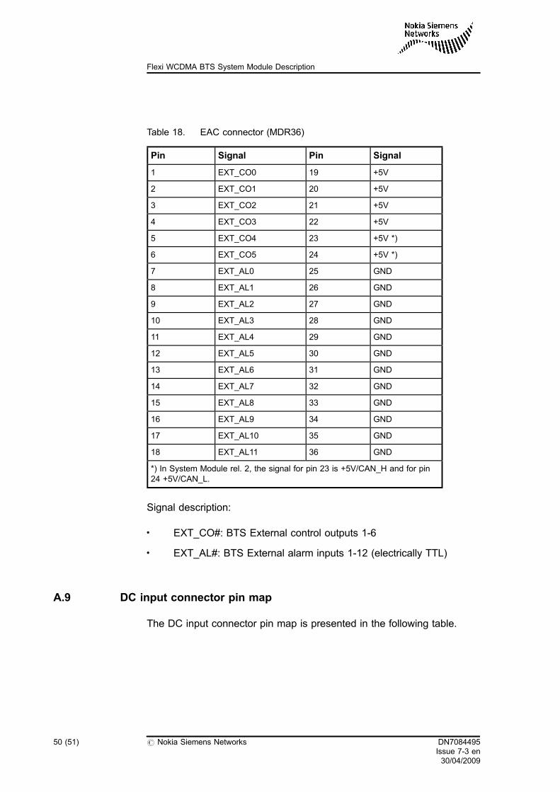
Table 18. EAC connector (MDR36)
Pin Signal Pin Signal
1 EXT_CO0 19 +5V
2 EXT_CO1 20 +5V
3 EXT_CO2 21 +5V
4 EXT_CO3 22 +5V
5 EXT_CO4 23 +5V *)
6 EXT_CO5 24 +5V *)
7 EXT_AL0 25 GND
8 EXT_AL1 26 GND
9 EXT_AL2 27 GND
10 EXT_AL3 28 GND
11 EXT_AL4 29 GND
12 EXT_AL5 30 GND
13 EXT_AL6 31 GND
14 EXT_AL7 32 GND
15 EXT_AL8 33 GND
16 EXT_AL9 34 GND
17 EXT_AL10 35 GND
18 EXT_AL11 36 GND
*) In System Module rel. 2, the signal for pin 23 is +5V/CAN_H and for pin24 +5V/CAN_L.
Signal description:
. EXT_CO#: BTS External control outputs 1-6
. EXT_AL#: BTS External alarm inputs 1-12 (electrically TTL)
A.9 DC input connector pin map
The DC input connector pin map is presented in the following table.
50 (51) # Nokia Siemens Networks DN7084495Issue 7-3 en30/04/2009
Flexi WCDMA BTS System Module Description

Table 19. DC input connector (Terminal block)
Pin Signal
Left V48N (-)
Right V48RTN (+)
Signal description:
. V48#: -48VDC power supply
A.10 Grounding connector pin map
The grounding connector pin map is presented in the following table.
Table 20. Grounding connector (screw terminal).
Description Signal
Ground GND
DN7084495Issue 7-3 en30/04/2009
# Nokia Siemens Networks 51 (51)
System Module connector pin maps