flexible piezoelectric nano-composite films for kinetic
TRANSCRIPT

Flexible piezoelectric nano-composite films for kinetic energy
harvesting from textiles
Ahmed Almusallama, Zhenhua Luob, Abiodun Komolafea, Kai Yanga, Andrew Robinsonc, Russel Toraha and Steve
Beebya* a Department of Electronics and Computer Science (ECS), University of Southampton, Southampton, SO17 1BJ, UK b School of Water, Energy and Environment, Cranfield University, College Road, Cranfield, MK43 0AL, UK c Faculty of Engineering and the Environment, University of Southampton, Southampton, SO17 1BJ, UK
* Corresponding author
Abstract. This paper details the enhancements in the dielectric and piezoelectric properties of a low-temperature screen-
printable piezoelectric nano-composite film on flexible plastic and textile substrates. These enhancements involved
adding silver nano particles to the nano-composite material and using an additional cold isostatic pressing (CIP) post-
processing procedure. These developments have resulted in a 18% increase in the free-standing piezoelectric charge
coefficient d33 to a value of 98 pC/N. The increase in the dielectric constant of the piezoelectric film has, however,
resulted in a decrease in the peak output voltage of the composite film. The potential for this material to be used to
harvest mechanical energy from a variety of textiles under compressive and bending forces has been evaluated
theoretically and experimentally. The maximum energy density of the enhanced piezoelectric material under 800 N
compressive force was found to be 34 J/m3 on a Kermel textile. The maximum energy density of the enhanced
piezoelectric material under bending was found to be 14.3 J/m3 on a cotton textile. These results agree very favourably
with the theoretical predictions. For a 10 cm x 10 cm piezoelectric element 100 m thick this equates to 38 J and 14.3
J of energy generated per mechanical action respectively which is a potentially useful amo unt of energy.
Keywords
Piezoelectric, nano-composite, energy harvesting, textiles, screen printed
1. Introduction
Electronic textiles (e-textiles) are a form of wearable technology that has the potential to revolutionise the
wearable technology sector. E-textile solutions face the same challenge as with all wearable devices,
namely that of supplying electrical power. At present the only solution is to use batteries and whilst this
suits rigid wearable devices, they are less compatible with flexible textiles and the requirement to
periodically charge the battery is an ongoing inconvenience. Energy harvesting potentially provides an
alternative power source that could replace or augment a battery solution. This paper explores the potential
of a flexible piezoelectric film screen printed onto a textile for harvesting mechanical energy from the
textile and converting it into electrical energy [1-3]. One application of such an approach would be to
harvest the kinetic energy present in human movement that would cause clothing fabric to flex and
compress. The compressive and bending forces would be transferred to the piezoelectric film enabling the
mechanical to electrical energy transduction process to occur. Piezoelectric transduction is a very widely
used method for harvesting mechanical energy and many example devices have been published including
cantilever based structures with bonded bulk [4] and screen printed [5] lead zirconate titanate (PZT). More
recently, nano-scale materials have been explored such as ZnO nanowires [6] and BaTiO3 nanofibres
aligned within a flexible polydimethylsiloxane (PDMS) matrix [7].
To be used in such an application, the piezoelectric materials needs to be flexible thereby minimising
its effect on the feel of the textile and the user’s comfort. The common piezoelectric materials, such as
PZT ceramics, possess excellent dielectric and piezoelectric properties but are physically hard and brittle
and are inherently unsuitable for such an application. Alternative polymer piezoelectric materials, such as
polyvinylidenefluride (PVDF) and associated co-polymers, are flexible and can be cured at low
temperature, which is suitable for use with fabrics. PVDF yarns have also been woven into a textile [8]
but the typical piezoelectric coefficients e.g. d33 are an order of magnitude lower than ceramic PZT being

in the range of 13 to 38 pC/N [9]. This results in lower energy conversion efficiency and limits the power
output of the energy harvester.
This paper investigates the use of a screen printable piezoelectric composite to form an active film
on the surface of the textile for energy harvesting. Formulated correctly, it offers the potential for improved
piezoelectric properties compared with PVDF as well as a suitable degree of flexibility provided by the
polymer binder. The most common and most straightforward to formulate piezoelectric composite is the
0-3 type which contains piezoelectric ceramic powder dispersed in a polymer or epoxy binder [10, 11].
The 0-3 type piezoelectric composites can be deposited on to a substrate using a number of techniques,
but this work used screen-printing since it is a straightforward and scalable process that is widely used in
the textile industry.
The piezoelectric response of a piezoelectric composite is typically affected by a reduction in the
effective electric field (Eeff) during the poling process [12]. This is caused by the lower dielectric constant
and higher resistivity of the polymer phase of the composite compared to the ceramic phase, which traps
the applied electric field within the polymer matrix, and the Eeff applied across the piezoelectric particle
is reduced. Eeff can also be reduced by air voids within the composite introduced during mixing of the
composite, or during the curing process when the solvent is evaporated. These air voids also reduce the
overall dielectric constant and increase the resistivity of the film, consequently reducing the Eeff on the
piezoelectric particles.
To minimize the reduction in Eeff, in this work we report on an investigation into the addition of
silver nano-particles into the polymer matrix. Adding conductive particles into the composite can
significantly lower the resistivity of the polymer phase [13], thus increasing the Eeff on the piezoelectric
particles. Previous studies have investigated a number of additives in piezoelectric composite, such as
carbon nanotubes [14], micron-sized Ag particles [15], and Ag nanowires [16]. This work used nano-sized
Ag particles (average size of 100 nm) in the composite.
This paper builds upon previously published investigations into the formulation of a low temperature
screen printable piezoelectric composite carried out at Southampton. This work takes the previously best
performing formulation [17] and reports on the effect of adding different amounts of Ag nano particles on
the film properties. The work also uses cold isostatic press (CIP) post-processing, which was previously
found to reduce the air voids in the composite [18]. The improved piezoelectric composite ink has been
printed on 4 types of flexible substrates (Kapton, cotton, polyester cotton and Kermel) and the energy
harvesting potential of this approach has been evaluated both theoretically and experimentally.
Characterizing equations and experiments are presented that apply to the printed films under compressive
and bending forces. The influence of the mechanical properties of the flexible substrates on the energy
harvesting performance are also explored since this has previously been demonstrated to have an effect
on the measured d33 or the printed films [19].
2. Materials and Methods
2.1 Formulating piezoelectric composite paste
In this work, a mixture of piezoelectric ceramic particles and polymeric binder was used to make the
piezoelectric composite paste. The polymeric binder was formed by mixing a thermoplastic polymer with
γ-butyrolactone solvent to produce a thixotropic paste. Lead zircontate titanante (PZT) piezoelectric
ceramic powder, type PZT-5H was used as the active material in the composite. The ceramic powder was
a blend of PZT particles with an average particle size of 2 µm (Pz29, Ferroperm) and 0.8 µm (S-55,
Sunnytec) with weight ratio of 4:1. This blend PZT powder sizes has been previously identified as a
suitable combination form maximizing the density of the piezoelectric particles with the smaller particles
filling the voids between the larger particles [17]. The PZT powder mixture was blended with the
polymeric binder in a weight ratio of 2.57:1, making a printable paste.
The Ag nanoparticles with an average particle size of 100 nm (Sigma Aldrich) were added to the paste.
The dielectric and piezoelectric properties of the printable paste were investigated for different Ag weight

percentages of 0.05, 0.1, 0.2, 0.5, 1 and 2, respectively. The mixture was first hand mixed using spatula
and then placed in a DAC 150 SpeedMixer (Synergy Device Limited) for 2 minutes. The mixtures were
finally processed in a triple-roll mill (Exact 501) to further improve the PZT and Ag powder dispersion
and to minimize trapped air in the dispersion. A schematic of the formulation process is shown in figure
1(a).
Figure 1: Schematic showing (a) the mixing process of the PZT-Ag-polymer composite; (b) the screen printing process;
(c) the printed capacitive structure on woven-fabric substrate; (d) the CIP process.
2.2 Screen-printing and curing the piezoelectric paste
The piezoelectric material and other associated layers were screen-printed using a DEK 248 semi-
automatic screen-printer (DEK Printing Machines Ltd) and stainless steel mesh screens (see figure 1(b)).
The piezoelectric composite was printed in a standard parallel plate capacitor structure with the
piezoelectric film sandwiched between two electrodes as shown in figure 1(c). This capacitor structure
enables contact poling of the piezoelectric material and straightforward connection to the electrodes for
the measurement of d33 and in actual use. The screen-printing process was carried out on. In the case of
textiles, it is often necessary to first print a polymer interface layer on the surface of the fabric before
printing the other layers. This interface layer reduces the surface roughness and negates any surface
pilosity (protruding fibres) that would otherwise prevent the printing of consistent working samples [20].
The interface layer is a UV curable polyurethane based paste (Fabink-UV-IF1, Smart Fabric Inks). The
remaining films were all thermally cured in a box over, with the curing conditions of each printed layer
being shown in figure 1(c). The electrodes were printed using silver polymer ink from DuPont (DuPont
5000). The dimensions of the printed samples used in this study were 10 x 10 mm by approximately 100
m thick.

2.3 Poling process
Direct contact poling (DCP) was used to polarize the piezoelectric active particles in the composite. An
external electric field (E, MV/m) was applied for a specific period of time (t, min) with the sample held
at an elevated temperature (T, °C). E is defined by the equation E = V/d, where V and d are the applied
voltage and the thickness of the composite film, respectively. Throughout this study, the external electric
field used was 3.7 MV/m and the poling time was 6 minutes. The poling temperature varied between 70
and 90 oC depending upon the formulation and the exact values T for the different formulations and the
influence of the additives and post processes are discussed in the text below.
2.4 Cold isostatic pressing (CIP)
A commercial CIP machine (CIP-15, MTI Corporation USA) was used to eliminate the air voids in the
printed piezoelectric film. As schematically shown in figure 1(d), the vertical applied force on the die
pressurizes the hydraulic fluid inside the vessel, resulting in a homogenous pressure that is applied to the
sample. This increases the density of the composite phases (PZT, Ag particles and polymer) and reduces
the air voids. An Scanning Electron Microscope (SEM) image of the top of the cured and pressed
piezoelectric film is shown in figure 2.
Figure 2: SEM image of the cured and pressed piezoelectric layer
2.5 Flexible substrates
The paste was screen-printed on two types of substrates, Kapton polyimide 300HN (75 µm, KATCO) and
woven-fabrics. The Kapton substrate is mainly used as a reference for investigating the dielectric and
piezoelectric properties of the composite. The piezoelectric composite on woven-fabric substrates is the
main focus in this study. The outputs (voltage, power and energy) of the printed composite on the woven-
fabric substrates were measured under compressive and bending forces. The investigated woven-fabric
substrates were polyester-cotton (65% polyester), cotton, and polyamide-imide (Kermel). Table 1 lists the
Young’s modules (Yf) and Poisson ratio (v) of the fabrics, interface layer and deposited films. The
effective Young’s modulus and Poisson ratio of each composite were calculated using the following
equations.
𝑌𝑠𝑢𝑏 = 𝑌𝑓 . 𝑉𝑓 + 𝑌𝑖𝑛𝑡. 𝑉𝑖𝑛𝑡 (1)
𝜐𝑠𝑢𝑏 = 𝜐𝑓 . 𝑉𝑓 + 𝜐𝑖𝑛𝑡. 𝑉𝑖𝑛𝑡 (2)

Where, Ysub, υsub, Yf, υf, Yint, and υint are the Young’s modulus and Poisson ratio of the substrate, fabrics
and interface layer, respectively. Since the volume fraction of the interface layer for cotton, polyester-
cotton and Kermel substrates are 0.7, 0.7 and 0.4 respectively, the Young’s modulus and Poisson ratio of
the substrates were estimated and are given in Table 2. The values in Table 2 were used to calculate the
theoretical voltage output of the composite in the following section.
Table 1: Mechanical properties of substrates and the piezoelectric film
Material Direction Young’s modulus
(MPa)
Average Poisson ratio
ν
Cotton Warp 505 0.5
Weft 415
Polyester-cotton Warp 534 0.42
Weft 356
Kermel Warp 247 0.38
Weft 244
Interface layer - 100 0.47
Kapton - 2500 0.34
Piezoelectric film - 131 0.4
Table 2: Mechanical properties of the substrates (woven-fabric plus interface)
Woven-fabric plus
interface layer
Y
(MPa)
υ
Cotton 352 0.491
Polyester-cotton 342 0.435
Kermel 158 0.434
3. Analytical modelling of energy output
The piezoelectric composite is modelled as a unimorph piezo-beam under compressive and bending
conditions. Due to the mechanical behaviour of fabrics under these loads, the elastic properties of the
fabrics were characterized based on [21] to improve the correlation between the experimental and
theoretical results. The energy outputs of the composite due to compressive and bending stresses are
characterised as follows:
(a) Compressive case
The voltage ouput of the piezoelectric composite on woven-fabric substartes can be predicted using
analytical modelling. The following three constitutive equations describe the mechanical and electrical
behaviour of the piezoelectric element and these use the standard subscript notation to describe the vector
directions.
𝑆1 = 𝑠11𝐸 𝑇1 + 𝑠12
𝐸 𝑇3 + 𝑑31𝐸3 (3)
𝑆3 = 𝑠13𝐸 (𝑇1 + 𝑇2) + 𝑠33
𝐸 𝑇3 + 𝑑33𝐸3 (4)
𝐷3 = 𝜀3𝑇𝐸3 + 𝑑31(𝑇1 + 𝑇2) + 𝑑33𝑇3 (5)
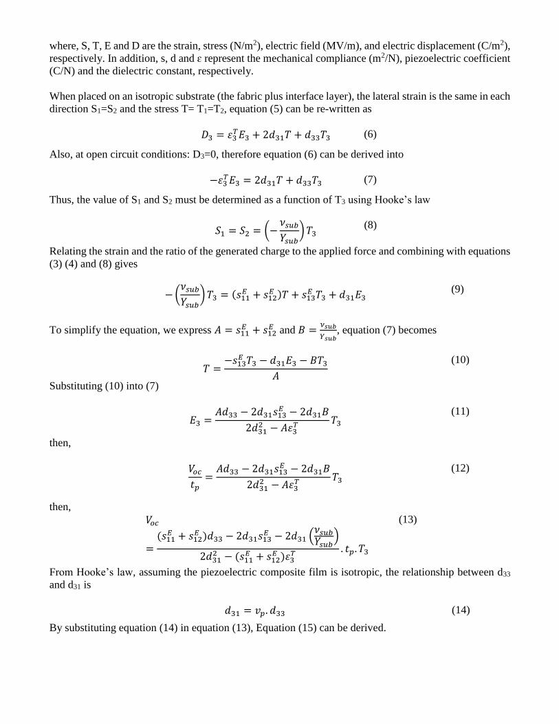
where, S, T, E and D are the strain, stress (N/m2), electric field (MV/m), and electric displacement (C/m2),
respectively. In addition, s, d and ɛ represent the mechanical compliance (m2/N), piezoelectric coefficient
(C/N) and the dielectric constant, respectively.
When placed on an isotropic substrate (the fabric plus interface layer), the lateral strain is the same in each
direction S1=S2 and the stress T= T1=T2, equation (5) can be re-written as
𝐷3 = 𝜀3𝑇𝐸3 + 2𝑑31𝑇 + 𝑑33𝑇3 (6)
Also, at open circuit conditions: D3=0, therefore equation (6) can be derived into
−𝜀3𝑇𝐸3 = 2𝑑31𝑇 + 𝑑33𝑇3 (7)
Thus, the value of S1 and S2 must be determined as a function of T3 using Hooke’s law
𝑆1 = 𝑆2 = (−𝜈𝑠𝑢𝑏
𝑌𝑠𝑢𝑏) 𝑇3
(8)
Relating the strain and the ratio of the generated charge to the applied force and combining with equations
(3) (4) and (8) gives
− (𝜈𝑠𝑢𝑏
𝑌𝑠𝑢𝑏) 𝑇3 = (𝑠11
𝐸 + 𝑠12𝐸 )𝑇 + 𝑠13
𝐸 𝑇3 + 𝑑31𝐸3 (9)
To simplify the equation, we express 𝐴 = 𝑠11𝐸 + 𝑠12
𝐸 and 𝐵 =𝜈𝑠𝑢𝑏
𝑌𝑠𝑢𝑏, equation (7) becomes
𝑇 =−𝑠13
𝐸 𝑇3 − 𝑑31𝐸3 − 𝐵𝑇3
𝐴
(10)
Substituting (10) into (7)
𝐸3 =𝐴𝑑33 − 2𝑑31𝑠13
𝐸 − 2𝑑31𝐵
2𝑑312 − 𝐴𝜀3
𝑇 𝑇3 (11)
then,
𝑉𝑜𝑐
𝑡𝑝=
𝐴𝑑33 − 2𝑑31𝑠13𝐸 − 2𝑑31𝐵
2𝑑312 − 𝐴𝜀3
𝑇 𝑇3 (12)
then,
𝑉𝑜𝑐
=(𝑠11
𝐸 + 𝑠12𝐸 )𝑑33 − 2𝑑31𝑠13
𝐸 − 2𝑑31 (𝜈𝑠𝑢𝑏
𝑌𝑠𝑢𝑏)
2𝑑312 − (𝑠11
𝐸 + 𝑠12𝐸 )𝜀3
𝑇 . 𝑡𝑝. 𝑇3
(13)
From Hooke’s law, assuming the piezoelectric composite film is isotropic, the relationship between d33
and d31 is
𝑑31 = 𝑣𝑝. 𝑑33 (14)
By substituting equation (14) in equation (13), Equation (15) can be derived.
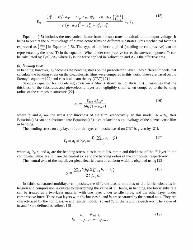
𝑉𝑜𝑐 =(𝑠11
𝐸 + 𝑠12𝐸 ). 𝑑33 − 2𝑣𝑝. 𝑑33. 𝑠13
𝐸 − 2𝑣𝑝. 𝑑33. (𝜈𝑠𝑢𝑏
𝑌𝑠𝑢𝑏)
2. (𝑣𝑝 . 𝑑33)2
− (𝑠11𝐸 + 𝑠12
𝐸 ). 𝜀3𝑇
. 𝑡𝑝. 𝑇3
(15)
Equation (15) includes the mechanical factor from the substrates to calculate the output voltage. It
helps to predict the output voltage of piezoelectric films on different substrates. This mechanical factor is
expressed as (𝝂𝒔𝒖𝒃
𝒀𝒔𝒖𝒃) in Equation (15). The type of the force applied (bending or compressive) can be
represented by the stress T3 in the equation. When under compressive force, the stress component T3 can
be calculated by T3=F3/Ae, where F3 is the force applied in 3-direction and Ae is the effective area.
(b) Bending case
In bending, however, T3 becomes the bending stress on the piezoelectric layer. Two different models that
calculate the bending stress on the piezoelectric films were compared in this work. These are based on the
Stoney’s equation [22] and classical beam theory (CBT) [21].
Stoney’s equation for calculating stress on a film is shown in Equation (16). It assumes that the
thickness of the substrates and piezoelectric layer are negligibly small when compared to the bending
radius of the composite structure [22].
𝜎𝑓 = 𝑌𝑠𝑢𝑏 ℎ𝑠𝑢𝑏
2 𝑟
6ℎ𝑓(1 − 𝜐𝑠𝑢𝑏)
(16)
where 𝜎𝑓 and ℎ𝑓 are the stress and thickness of the film, respectively. In this model, 𝜎𝑓 = 𝑇3 , thus
Equation (16) can be substituted into Equation (15) to calculate the output voltage of the piezoelectric film
in bending.
The bending stress on any layer of a multilayer composite based on CBT is given by [21]:
𝑇3 = 𝜎𝑖 = 𝑌𝑖𝜖𝑖 = 𝑌𝑖 (∑ ℎ𝑗
𝑖𝑗=1 − )
𝑟
(17)
where 𝜎𝑖, 𝑌𝑖, 𝜖𝑖 and ℎ𝑖 are the bending stress, elastic modulus, strain and thickness of the ith layer in the
composite, while and 𝑟 are the neutral axis and the bending radius of the composite, respectively.
The neutral axis of the multilayer piezoelectric beam of uniform width is obtained using [23]:
= ∑ 𝑌𝑖ℎ𝑖(2 ∑ ℎ𝑗 − ℎ𝑖
𝑖𝑗=1 )𝑛
𝑖=1
2 ∑ 𝑌𝑖ℎ𝑖𝑛𝑖=1
(18)
In fabric-substrated multilayer composites, the different elastic modulus of the fabric substrates in
tension and compression is critical to determining the value of . Hence, in bending, the fabric substrate
can be treated as a two-layer material with one layer under tensile force, and the other layer under
compressive force. These two layers with thicknesses h1 and h2 are separated by the neutral axis. They are
characterized by the compressive and tensile moduli, YC and YT of the fabric, respectively. The value of
h1 and h2 are defined as follows [19]:
ℎ1 = 𝑓𝑎𝑏𝑟𝑖𝑐
ℎ2 = ℎ𝑓𝑎𝑏𝑟𝑖𝑐 − 𝑓𝑎𝑏𝑟𝑖𝑐
(19)

where, 𝑓𝑎𝑏𝑟𝑖𝑐 and ℎ𝑓𝑎𝑏𝑟𝑖𝑐 are the neutral axis and thickness of the fabric. Hence, in the model using CBT,
the value of T3 in Equation (17) can be obtained using the neutral axis in Equation (18), and then used to
calculate the output voltage of the piezoelectric film with Equation (15).
4. Results and Discussion
The results are divided into two parts. The first part relates to the improvements made to the piezoelectric
composite material whilst the second part reports the evaluation of the energy harvesting potential from
textiles using the improved piezoelectric material.
4.1 Dielectric and piezoelectric properties of the PZT-Ag-polymer nano-composite
Piezoelectric composites with Ag wt% of 0%, 0.05%, 0.1%, 0.2%, 0.5% and 1% were investigated.
These were screen-printed on to Kapton substrates and cured as described previously. Their dielectric
properties are shown in figure 3(a). The results show that the relative dielectric constant increases and
then decreases with increasing % weight content of Ag nano-particles with 0.2 wt% giving a dielectric
constant of 171. A similar trend to the relative dielectric constant is observed in the d33, as shown in figure
3(b). The d33 of the composite reaches a maximum value of 43.5 pC/N at 0.2 wt% of Ag in the composite,
showing an 8% increase compared to the composite without Ag. The d33 was found to decrease beyond
0.2 wt%. It should be noted that the poling temperature used varies with Ag wt%, being 90oC for 0%,
80oC for 0.05 and 0.1% and 75oC for 0.2 and 0.5%. The increasing Ag content was found to increase the
risk of short-circuiting during poling, which can be countered by reducing the poling temperature.
(a) (b) Figure 3 (a) Relative dielectric constant of the composite measured at 1 Hz, with increasing wt% of Ag nano-particles and (b)
d33 value of the PZT-Ag-polymer composite with different Ag wt% (poling temperature reduces with increasing %Ag)
Different substrates have a different effect on the measured d33 values due to the clamping effect
caused by the variation in mechanical boundary conditions of the substrates, which has been discussed in
our previous work [19]. Taking the relative mechanical properties of the Kapton and polyester-cotton
substrates into account and applying the theory presented in [19] then the 0.2 wt% Ag composite printed
on a polyester-cotton substrate would exhibit a freestanding d33 value of 76 pC/N.
4.2 Effect of CIP pressure on the dielectric, resistive and piezoelectric properties
Composite samples on Kapton with 0.2 wt% Ag content were next processed at different CIP pressures
and the relative dielectric constant, DC resistivity and piezoelectric properties of the samples measured.
For each CIP pressure, three samples were tested. The dielectric constant was found to increase with
110
120
130
140
150
160
170
180
0 0.05 0.1 0.2 0.5 1
Rel
ativ
e d
iele
ctri
c co
nst
ant
ɛ r
Ag Nano (wt%)
0
5
10
15
20
25
30
35
40
45
50
0 0.05 0.1 0.2 0.5
d33
(pC
/N)
Ag-Nano (wt%)

increasing CIP pressure, as shown in figure 4(a), whilst the DC resistivity decreases. The application of a
CIP pressure of 250 MPa for 2 minutes was found to lead to a 44% increase in the dielectric constant and
a decrease of 52.8% in the DC resistivity. The reduction in resistivity can cause breakdown at high electric
fields during the polarization process. To offset this, the poling temperature was reduced to 70oC for the
samples pressurized at 250 MPa. Figure 4(b) shows the effect of increasing CIP pressure on the d33 values.
The samples pressurized by 250 MPa demonstrate a 9% increase in d33 compared to the samples with 0.2
wt% Ag but without CIP processing. Combined, the addition of the Ag nano particles and the use of CIP
yields d33 of 49 pC/N on Kapton, an increase in the measured d33 of 9 pC/N compared to the original
composite. All samples were poled at 75oC apart from the CIP pressure of 250 MPa, which was poled at
70oC to ensure reliable poling.
(a) (b)
Figure 4 (a) Relative dielectric constant (at 20 Hz and 1 kHz) and DC resistivity of the samples with increasing CIP pressure
and processing time of 2 mins and (b) d33 values of the samples processed at different CIP pressures.
Table 3 shows a summary of improvements in the dielectric, piezoelectric and resistive properties of
the composite by adding Ag nano-particles and applying the CIP process compared with the original
formulation. The summary includes the piezoelectric properties for films printed on Kapton, polyester-
cotton (as an example of the woven-fabric substrate), and free-standing. The free-standing d33 value is
calculated from the measured d33 value to determine the actual d33 if there was no substrate [19]. Table 4
give other mechanical properties of the original piezoelectric composite film.
Table 3: Summary of the improvement in the dielectric, piezoelectric and resistive properties
Sample type Kapton Polyester-cotton Free-standing
ɛr (at
1 kHz)
Rv
(GΩ.m) d33
(pC/N)
g33
(mV.m/N)
d33
(pC/N)
g33
(mV.m/N)
d33
(pC/N)
g33
(mV.m/N)
Original 146 12.5 40 30.9 70 54.2 80 62
Original + CIP
(250 MPa)
211 7.1 45 24
76.6 41
90 48.2
0.2 wt% Ag 171 11.7 43.5 28.7
76 50.2
87.5 57.8
0
2
4
6
8
10
12
0
50
100
150
200
250
300
350
0 100 200 300
DC
res
isti
vity
(G
Ω.m
)
Rel
ativ
e d
iele
ctri
c co
nst
ant
ɛ r
CIP Pressure (MPa)
Dielectric constant @ 1kHz
Dielectric constant @ 20Hz
DC resistivity
20
25
30
35
40
45
50
55
0 41 83 166 250
d3
3(p
C/N
)
CIP pressure (MPa)
0.2 wt% Ag +
CIP (250 MPa)
262 5.9 49 21.1
83 35.8
98 42.2
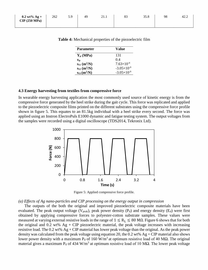
Table 4: Mechanical properties of the piezoelectric film
Parameter Value
Yp (MPa) 131
υp 0.4
s11 (m2/N) 7.63×10⁻⁹
s12 (m2/N) -3.05×10⁻⁹
s13 (m2/N) -3.05×10⁻⁹
4.3 Energy harvesting from textiles from compressive force
In wearable energy harvesting application the most commonly used source of kinetic energy is from the
compressive force generated by the heel strike during the gait cycle. This force was replicated and applied
to the piezoelectric composite films printed on the different substrates using the compressive force profile
shown in figure 5. This equates to an 81.5kg individual with a heel strike every second. The force was
applied using an Instron ElectroPuls E1000 dynamic and fatigue testing system. The output voltages from
the samples were recorded using a digital oscilloscope (TDS2014, Tekronix Ltd).
Figure 5: Applied compressive force profile.
(a) Effects of Ag nano-particles and CIP processing on the energy output in compression
The outputs of the both the original and improved piezoelectric composite materials have been
evaluated. The peak output voltage (Vpeak), peak power density (Pd) and energy density (Ed) were first
obtained by applying compressive forces to polyester-cotton substrate samples. These values were
measured at varying external resistive loads in the range of 1 ≤ RL ≤ 80 MΩ. Figure 6 shows that for both
the original and 0.2 wt% Ag + CIP piezoelectric material, the peak voltage increases with increasing
resistive load. The 0.2 wt% Ag + CIP material has lower peak voltage than the original. As the peak power
density was calculated from the peak voltage using equation 20, the 0.2 wt% Ag + CIP material also shows
lower power density with a maximum Pd of 160 W/m3 at optimum resistive load of 40 MΩ. The original
material gives a maximum Pd of 434 W/m3 at optimum resistive load of 10 MΩ. The lower peak voltage
0
200
400
600
800
1000
0 0.8 1.6 2.4 3.2 4
Forc
e (
N)
Time (s)

of the 0.2 wt% Ag + CIP piezoelectric material is due to its lower g33, which is caused by the increased
dielectric constant, as shown in Figures 3 and 4.
Pd =Vpeak
2
RLVf
(20)
Figure 6: Output peak voltage and power density of the original and 0.2 wt% Ag + CIP materials on polyester-cotton under
compression.
Figure 7 shows the variation in energy densities of the original and 0.2 wt% Ag + CIP composite
materials with increasing the external resistive load. The energy density is calculated using the equation
21, where t1 and t2 represent the beginning and end time of the pulse generated by compressing the sample.
The maximum energy density of the 0.2 wt% Ag + CIP composite is 24 J/m3 at an optimum resistive load
of 50 MΩ, and for the original composite is 12 J/m3 at 20 MΩ. The increase in Ep is due to the increase
of d33 in the improved composite materials and the longer duration of the pulse (t2 – t1) compared with the
original material (see inset in figure 8). As shown in Table 3, d33 increases with increasing ɛr, leading to
an overall increase in output energy.
𝐸 = 𝑉𝑓 ∫𝑉(𝑡)2
𝑅
𝑡2
𝑡1. 𝑑𝑡 (21)
0
50
100
150
200
250
300
350
400
450
500
0
2
4
6
8
10
12
14
0 10 20 30 40 50 60 70 80 90
Po
we
r D
en
sity
(W
/m3 )
Ou
tpu
t vo
ltag
e (
V)
Resistive load (MΩ)
Peak voltage (0.2 wt% Ag + CIP)
Peak voltage (original)
Power density (0.2 wt% Ag + CIP)
Power density (original)
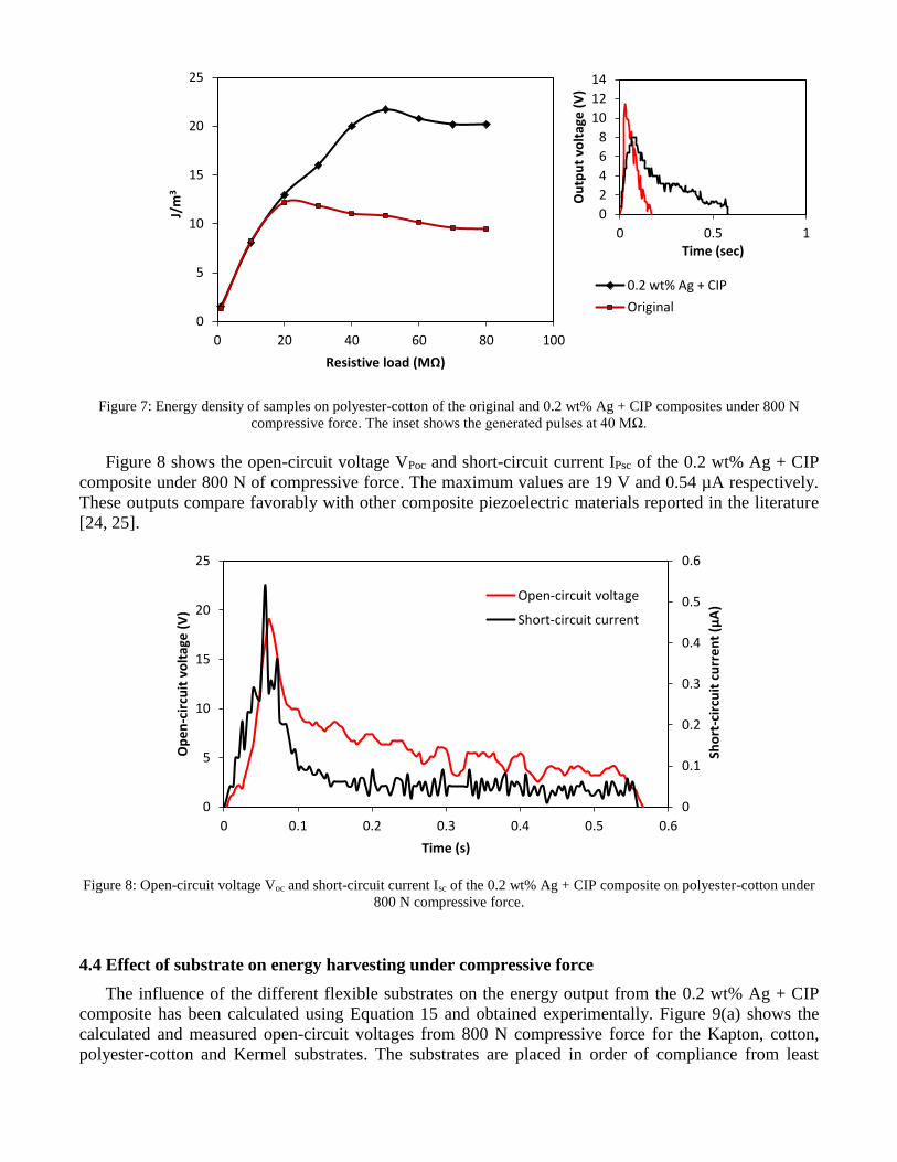
Figure 7: Energy density of samples on polyester-cotton of the original and 0.2 wt% Ag + CIP composites under 800 N
compressive force. The inset shows the generated pulses at 40 MΩ.
Figure 8 shows the open-circuit voltage VPoc and short-circuit current IPsc of the 0.2 wt% Ag + CIP
composite under 800 N of compressive force. The maximum values are 19 V and 0.54 µA respectively.
These outputs compare favorably with other composite piezoelectric materials reported in the literature
[24, 25].
Figure 8: Open-circuit voltage Voc and short-circuit current Isc of the 0.2 wt% Ag + CIP composite on polyester-cotton under
800 N compressive force.
4.4 Effect of substrate on energy harvesting under compressive force
The influence of the different flexible substrates on the energy output from the 0.2 wt% Ag + CIP
composite has been calculated using Equation 15 and obtained experimentally. Figure 9(a) shows the
calculated and measured open-circuit voltages from 800 N compressive force for the Kapton, cotton,
polyester-cotton and Kermel substrates. The substrates are placed in order of compliance from least
0
5
10
15
20
25
0 20 40 60 80 100
J/m
3
Resistive load (MΩ)
0.2 wt% Ag + CIP
Original
0
0.1
0.2
0.3
0.4
0.5
0.6
0
5
10
15
20
25
0 0.1 0.2 0.3 0.4 0.5 0.6
Sho
rt-c
ircu
it c
urr
en
t (μA
)
Op
en
-cir
cuit
vo
ltag
e (
V)
Time (s)
Open-circuit voltage
Short-circuit current
0
2
4
6
8
10
12
14
0 0.5 1
Ou
tpu
t vo
ltag
e (
V)
Time (sec)
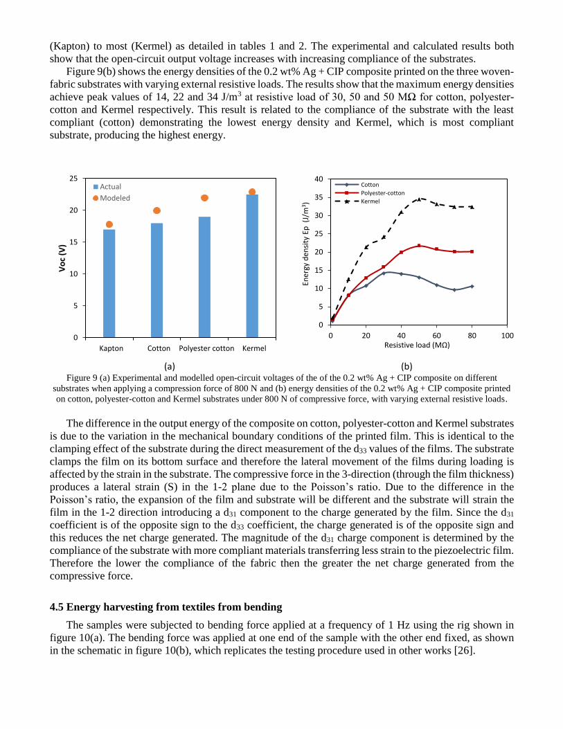
(Kapton) to most (Kermel) as detailed in tables 1 and 2. The experimental and calculated results both
show that the open-circuit output voltage increases with increasing compliance of the substrates.
Figure 9(b) shows the energy densities of the 0.2 wt% Ag + CIP composite printed on the three woven-
fabric substrates with varying external resistive loads. The results show that the maximum energy densities
achieve peak values of 14, 22 and 34 J/m3 at resistive load of 30, 50 and 50 MΩ for cotton, polyester-
cotton and Kermel respectively. This result is related to the compliance of the substrate with the least
compliant (cotton) demonstrating the lowest energy density and Kermel, which is most compliant
substrate, producing the highest energy.
(a) (b) Figure 9 (a) Experimental and modelled open-circuit voltages of the of the 0.2 wt% Ag + CIP composite on different
substrates when applying a compression force of 800 N and (b) energy densities of the 0.2 wt% Ag + CIP composite printed
on cotton, polyester-cotton and Kermel substrates under 800 N of compressive force, with varying external resistive loads.
The difference in the output energy of the composite on cotton, polyester-cotton and Kermel substrates
is due to the variation in the mechanical boundary conditions of the printed film. This is identical to the
clamping effect of the substrate during the direct measurement of the d33 values of the films. The substrate
clamps the film on its bottom surface and therefore the lateral movement of the films during loading is
affected by the strain in the substrate. The compressive force in the 3-direction (through the film thickness)
produces a lateral strain (S) in the 1-2 plane due to the Poisson’s ratio. Due to the difference in the
Poisson’s ratio, the expansion of the film and substrate will be different and the substrate will strain the
film in the 1-2 direction introducing a d31 component to the charge generated by the film. Since the d31
coefficient is of the opposite sign to the d33 coefficient, the charge generated is of the opposite sign and
this reduces the net charge generated. The magnitude of the d31 charge component is determined by the
compliance of the substrate with more compliant materials transferring less strain to the piezoelectric film.
Therefore the lower the compliance of the fabric then the greater the net charge generated from the
compressive force.
4.5 Energy harvesting from textiles from bending
The samples were subjected to bending force applied at a frequency of 1 Hz using the rig shown in
figure 10(a). The bending force was applied at one end of the sample with the other end fixed, as shown
in the schematic in figure 10(b), which replicates the testing procedure used in other works [26].
0
5
10
15
20
25
Kapton Cotton Polyester cotton Kermel
Vo
c (V
)
Actual
Modeled
0
5
10
15
20
25
30
35
40
0 20 40 60 80 100
Ener
gy d
ensi
ty E
p (
J/m
3 )
Resistive load (MΩ)
Cotton
Polyester-cotton
Kermel

(a) (b)
Figure 10: (a) The bending test rig and (b) schematic showing bending force applied to the test sample
(a) Effects of Ag nano-particles and CIP processing on the energy output in bending
Similar to the results from compression test, the peak voltage and power density of the 0.2 wt% Ag +
CIP composite are lower than the original, as shown in Figure 11. This is again due to the lower g33 and
higher d33 of the 0.2 wt% Ag + CIP material.

Figure 11: Output peak voltage and power density of the original and 0.2 wt% Ag + CIP composites under the same bending
force. Polyester-cotton was used as substrate for both samples.
The 0.2 wt% Ag + CIP composite produced a maximum VPoc of 17 V and maximum IPsc of 0.34 µA,
as shown in Figure 12. These values are higher than those previously reported [26].
Figure 12: Open-circuit voltage Voc and short-circuit current Isc when applying bending force at 1 Hz on the 0.2 wt% Ag +
CIP composite
Similar to the results of the compression test in figure 7, the 0.2 wt% Ag + CIP composite shows
higher energy densities than the original material, as shown in figure 13. The processed sample shows a
peak energy density of 12 J/m3 at 50 MΩ, and the sample without processing shows peak energy density
of 11 J/m3 at 70 MΩ. This is due to the higher d33 of the processed film.
0
10
20
30
40
50
60
70
80
90
0
1
2
3
4
5
6
7
8
9
0 20 40 60 80 100
Po
wer
den
sity
(W
/m3 )
Ou
tpu
t p
eak
volt
age
(V)
Resistive load (MΩ)
Peak voltage (0.2 wt%Ag + CIP)
Peak voltage (original)
Power density (0.2 wt%Ag + CIP composite)
Power density (original)
0
0.05
0.1
0.15
0.2
0.25
0.3
0.35
0.4
0
2
4
6
8
10
12
14
16
18
20
0 0.1 0.2 0.3 0.4 0.5 0.6 0.7
Sho
rt-c
ircu
it c
urr
ent
(μA
)
Op
en-c
ircu
it v
olt
age
(V)
Time (s)
Open-circuitvoltageShort-circuitcurrent
-2
0
2
4
6
8
0 0.5 1
Ou
tpu
t vo
ltag
e (
V)
Time (s)

Figure 13: Energy density of samples on polyester-cotton of the original and 0.2 wt% Ag + CIP composites during bending.
The inset shows the generated pulses at 50 MΩ.
(b) Effects of substrate on the energy output
Similar to the compression test, the output of the composite is also affected by the type of woven-
fabric substrate in the bending test. However, when in compression the output is mainly affected by the
mechanical boundary conditions of the substrates but the situation is more complex for the bending case.
From the model presented previously, the radius of curvature, bending rigidity and the neutral axis of the
system also affect the bending case. The voltage output calculated using Stoney’s model and the model
presented in this paper based on classical beam theory (CBT) are compared with experimental results in
figure 14(a). The CBT based model includes the effect of the substrate (i.e. the bending radius and neutral
axis) and is therefore more accurate than Stoney’s model. Figure 14(b) compares the energy densities of
the piezoelectric films on different fabric substrates. For the cotton, polyester-cotton and Kermel
substrates, their energy densities reach peak values of 14.3, 11.5 and 11.6 J/m3 at resistive loads of 70, 50
and 80 MΩ, respectively. It shows that cotton, which is least compliant among the three substrates,
produced the highest energy density because its increased stiffness couples more strain into the
piezoelectric composite film.
(a) (b)
0
2
4
6
8
10
12
14
0 10 20 30 40 50 60 70 80 90
Ep(J
/m3 )
Resistive load (MΩ)
0.2 wt% Ag + CIP
original
1
10
100
1000
Kapton Cotton Polyestercotton
Kermel
Vo
c (V
)
Actual
CBT based model
Modeled by Stoney's equation
0
2
4
6
8
10
12
14
16
0 20 40 60 80 100
Ener
gy d
ensi
ty E
p (
J/m
3 )
Resistive load (MΩ)
Cotton
PolyestercottonKermel

Figure 14 (a) Experimental and modeled open-circuit voltages of the 0.2 wt% Ag + CIP composite film on different woven-
fabrics when applying a bending at 1 Hz and a radius of curvature of 0.6 cm and (b) energy densities of the 0.2 wt% Ag +
CIP film printed on cotton, polyester-cotton and Kermel substrates when applying bending force at 1Hz, with varying
external resistive loads.
6. Conclusions
This work investigates the energy harvesting performance of PZT-polymer composite materials
printed on woven-fabric substrates. Clearly the energy harvesting performance is fundamentally linked to
the piezoelectric properties of the printed film. Diluting piezoceramic powder by placing it in a polymer
matrix will reduce the level of piezoelectric activity compared to bulk piezoceramic materials, but
measures such as the addition of Ag nano-particles and applying cold isostatic pressing has improved
performance. These measures have resulted in a 18% increase in the free-standing piezoelectric charge
coefficient d33 of the printed composite. The evaluation of the energy harvesting performance of the
improved piezoelectric composite printed on woven substrates has resulted in an increase in energy
density of 200% and 10% in compression and bending respectively. The increased dielectric constant has
led to a decrease in the piezoelectric voltage coefficient g33, thus lowering the peak output voltage.
The comparison between the different woven substrates shows that the energy output from the printed
piezoelectric composite is affected by the mechanical properties of the woven fabric. When placed in
compression, the highest energy output was obtained on the fabric with the smallest Young’s modulus,
i.e. the most compliant. On the other hand, when flexed or bent, the highest energy output was obtained
from the fabric with highest Young’s modulus. The models presented in this paper to describe the energy
output of the piezoelectric composite in compression and bending show good agreement with the
experimental results and are useful tools for predicting the output from such materials in these applications.
, the energy density results equate to 38 J
and 14.3 J of energy generated per mechanical action respectively. Piezoelectric harvesters are typically
fabricated on stiffer substrates such a metal or silicon and therefore other piezoelectric harvesters of
similar size would typically deliver more energy especially in bending. The compliance of the textile
substrates, which is a fundamentally desirable property for the comfort of the wearer, does reduce the
strain coupled to the piezoelectric film and hence the level of energy generated. Nonetheless, the energy
generated is a potentially useful amount and may be useful for powering wearable electronics in the future
as the levels of power consumption continue to fall.
Acknowledgements The authors gratefully acknowledge the EPSRC for supporting this research with grant reference
EP/I005323/1. The data for this paper can be found at DOI:10.5258/SOTON/403388.
Bio’s
Dr Ahmed Almusallam received the BS.c in electrical and computer engineering in
2006, the MS.c in Micro ElectroMechanical Systems (MEMS) from University of
Southampton, United Kingdom, in 2010 and completed his Ph.D from University of
Southampton, United Kingdom in 2016. His Ph.D research was to develop flexible
piezoelectric nano-composite materials for energy harvesting from textiles. His research
interests include energy harvesting (from various sources, e.g. vibration, human
movement, solar and thermoelectric), flexible electronics, developing piezoelectric
materials, sensors, e-textiles, nanofabrication, printed electronics and thick-film technology.
Dr Zhenhua Luo completed his PhD at University of New South Wales (Australia),
focusing on the development and characterization of lead-free piezoelectric materials.
During PhD he was awarded a fellowship and worked at Technical University
Darmstadt (Germany) as a visiting researcher. Based on his research on functional
materials, he designed an energy harvesting device and was granted a patent. He then
joined a start-up company to lead a R&D team on energy harvesting technology, and
later on joined University of Southampton as a post-doctoral research fellow in 2013.
He took up the current post as Lecturer in Energy Harvesting and Storage at Cranfield University in 2016.
He has expertise in energy harvesting technologies for applications in environmental sensor network,
structural health monitoring and wearable health monitoring. Within this context he has research interest
in the development of advanced functional materials and energy harvesting/sensing devices.
Dr. Abiodun Komolafe obtained a BSc (Hons) degree in Physics in 2007 at the University
of Ibadan, Nigeria. He obtained an MSc in Microelectromechanical systems in 2011 and
in 2016, obtained a PhD in printed circuits on fabrics from the University of Southampton.
He is experienced in the fabrication of e-textiles using screen printing and
photolithography technologies. He currently works as a Research Fellow in the University
of Southampton investigating novel manufacturing methods for making functional
electronics on textiles.
Dr Kai Yang received the BSc degree in material engineering from the Beijing Institute of Fashion
Technology, China, in 2004 and the PhD degree from the School of Chemistry, University of Leeds,
in 2009. She is a Senior Research Fellow in Electronics and Computer Science. Her research
interests include electronic textiles, ink formulations, printing, and wearables technologies.
Dr Andrew Robinson received an MEng in Aerospace Engineering at the University
of Southampton in 2007, and completed his PhD titled: the assessment of residual
stresses using thermoelastic stress analysis, in 2011 also at Southampton. He is now the
manager of the Testing and Structures Research Laboratory (TSRL) which is a leading
multidisciplinary facility covering a wide range of application areas, specifically
specialising in experimental mechanics, structural testing and non-contact imaging
techniques.
Dr Russel Torah graduated with a BEng (Hons) in Electronic Engineering in 1999
and an MSc in Instrumentation and Transducers in 2000, both from the University of
Southampton. Between 2001 and 2004 Russel obtained a PhD in Electronics from the
University of Southampton in the optimisation of thick-film piezoceramics. Since 2005
he has been a full time researcher at the University of Southampton where he is currently
a Senior Research Fellow. Dr Torah is a co-founder of the Smart Fabric Inks (in 2011)
company specialising in printed smart fabrics. Dr Torah’s research interests are
currently focused on smart fabric development but he also has extensive knowledge of
energy harvesting, sensors and transducers. Dr Torah has 82 publications.

Professor Steve P Beeby obtained a BEng (Hons) degree in Mechanical Engineering
from the Univeristy of Portsmouth, UK, in 1992. He obtained his PhD from the
University of Southampton, UK, in 1998 on the subject of MEMS resonant sensors. He
has been awarded two prestigious EPSRC Research Fellowships to investigate the
combination of screen printed active materials with micromachined structures and
textiles for energy harvesting. Following the first Fellowship, he became a lecturer in
ECS, was appointed a Reader in 2008 and was awarded a personal Chair in 2011. His
research interests include energy harvesting, e-textiles, MEMS and active printed materials development.
He leads the UK’s Energy Harvesting Network and is Chair of the International Steering Committee for
the PowerMEMS conference series. He is currently leading 3 UK funded research projects and has
previously been principal or co-investigator on a further 18 projects and co-ordinated 2 European Union
research projects. He has co-authored/edited four books including ‘Energy Harvesting for Autonomous
Systems’ (Artec House, Inc., Boston, London, 2010). He has given 14 invited talks and has over 200
publications and 10 patents. He has an h-Index of 39 with >9500 citations. He is a co-founder of Perpetuum
Ltd, a University spin-out based upon vibration energy harvesting formed in 2004, Smart Fabric Inks Ltd
and D4 Technology Ltd.
References:
[1] S. P. Beeby, J. M. Tudor, N. M. White, Meas. Sci. Technol. 17 (2006) R175-R195.
[2] C. R. Bowen, H. A. Kim, P. M. Weaver, S. Dunn, Energy Environ. Sci. 7 (2014) 25-44.
[3] Z. Luo, D. Zhu, J. Shi, S. Beeby, C. Zhang, P. Proynov, B. Stark, IEEE Trans. Dielectr. Electr. Insul.
32, (2015) 1360-1368, 2015.
[4] S. Roundy, P. K. Wright, Smart Mater. and Struct. 13 (2004) 1131-1142.
[5] D. Zhu, S. P. Beeby, M. J. Tudor, N. R. Harris, Sens. and Act. A 169 (2011) 317-325.
[6] X. Wang, Nano Energy 1 (2012) 13-24.
[7] J. Yan, Y. G. Jeong, Appl. Mater. Interfaces (2016) 15700-15709.
[8] R. L. Hadimani, D. V. Bayramol, N. Sion, T. Shah, L. Qian, S. Shi, E. Siores, Smart Mater. Struct. 22
(2014) 075017.
[9] K. S. Ramadan, D. Sameoto, S. Evoy, Smart Mater. Struct. 23 (2014) 033001
[10] T. Papakostas, N. White, Sensor. Rev 20 (2000) 135-139.
[11] K. Prashanthi, N. Miriyala, R. D. Gaikwad, W. Moussa, V. R. Rao, T. Thundat, Nano Energy 2 (2013)
923-932.
[12] T. Bhimasankaram, S. V. Suryanarayana, G. Prasad, Curr. Sci. 74 (1998) 967-976.
[13] E. Sancaktar and L. Bai "Electrically conductive adhesives", Polymers, vol.3, pp.427-466, 2011.
[14] Z. Ounaies, C. Park, J. Harrison, P. Lillehei, J. of Thermoplastic Composite Materials 21 (2008) 393-
409.
[15] H. L. Zhang, J-F. Li, B-P. Zhang, J. Electroceram.16 (2006) 413-417.
[16] W-S. Jung, M-J. Lee, S.J. Yoon, W-H. Lee, B-K. Ju, C-Y. Kang, Int. J. Appl. Ceram. Technol. 13
(2016) 480-486.
[17] A. Almusallam1, R. N. Torah, D. Zhu, M. J. Tudor, S. P. Beeby, J. of Phys.: Conf. Series 476 (2013)
012108.
[18] A. Almusallam, K. Yang, Z. Cao, D. Zhu, M. J. Tudor, S. P. Beeby, J. of Phys.: Conf. Series 557
(2014) 012083.
[19] A. Almusallam, K. Yang, D. Zhu, R. N. Torah, A. Komolafe, J. Tudor, S. P. Beeby, Smart Mater.
Struct. 24 (2015)115030.
[20] K. Yang, R. Torah, Y. Wei, S. Beeby, J. Tudor, Textile Research Journal 83 (2013) 2023-2031.
[21] A. O. Komolafe, PhD thesis, Electronics and Computer Science, University of Southampton, 2016.
[22] X. Feng, Y. Huang, A. J. Rosakis, Trans. of the ASME 74 (2007) 1276-1281.
[23] R. G. Ballas, in Piezoelectric muyltilayer beam bending actuators, ed, (2007) 54.

[24] S. Xu, Y.-W. Yeh, G. Poirier, M. C. McAlpine, R. A. Register, N. Yao, Nano Lett. 13 (2013)
2393−2398.
[25] B. K. Yun, Y. K. Park, M. Lee, N. Lee, W. Jo, S. Lee, et al., Nanoscale Res. Lett. 9 (2014) 4.
[26] K.-I. Park, M. Lee, Y. Liu, S. Moon, G.-T. Hwang, G. Zhu, et al., Adv. Mat. 24 (2012) 2999–3004.