flexural characteristics of reinforced concrete beam …ijetch.org/vol7/755-r022.pdf ·...
TRANSCRIPT

Abstract—It is well known that the concrete in the tension
zone is neglected in the design. Therefore, it is reasonable if the concrete on the tension zone uses a low compressive strength concrete by mixing them with the Styrofoam grains. The concrete that filled with the concrete grains is named with Styrofoam Filled Concrete (SFC). Styrofoam as waste can be used as a filler to reduce the volume of concrete, especially for areas where the concrete section is neglected in design. SFC used in this study were with 30% Styrofoam volume fractions. Results indicated that the BN had maximum flexural load of 38.8 kN, while BTL had decreased load of 24.2 kN and BTR of 36.0 kN, close to the normal beam specimen. Loading test of the BSC and BSCTR had maximum load of 38.2 kN and 48.3 kN, respectively. It can be concluded that the use of SFC in tension zone of the concrete beams showed a good agreement in performance compared to the normal reinforced concrete beams. The use of truss system reinforcement can increase the strength of the loading capacity of the beam is significant compared to the vertical reinforcement.
I. INTRODUCTION Concrete is still one of the most widely used materials in
the world and estimated that its annual global production is more than 2 billion meters cubic “unpublished” [1]. It is formed from a hardened mixture of cement, water, fine aggregate and coarse aggregate. As the main constituent of concrete materials, it is natural materials that decrease in number so that the study of natural materials that are used in the building structures optimum design is necessary to improve, especially in the bridge girder.
Of the various theories related to the analysis of structural elements concrete beams, it is noted that the part that its power is maximally worked in withstand bending style is the outer part only. Rose in the concrete which is compresed, while the tensile concrete which experiences strength is negligible [2]. Therefore it is not efficient when the unoptimally working concrete core parts is made from the same type of optimally working concrete.
Because of these inefficiency then aroses an opinion to make concrete that consists of several different layers [3]. The concrete beam that consists of several different layers,
Manuscript received April 15, 2014; revised June 5, 2014. This work was
supported in part by the Department of Public Work, Konawe Regency, Province of South-East Sulawesi, Indonesia under Grant SK.02/2012, and The Effect of Truss System Reinforcement for Flexural Characteristics of The Structural Element Styrofoam Filled Reinforced Concrete Beam.
The authors are with the Civil Engineering Department, Hasanuddin University, Makassar, Post Code 90245 Indonesia (e-mail: [email protected], [email protected], [email protected], [email protected]).
with this, we can make the element design of beam structure made from concrete more effecient by using normal concrete in certain layers while the other part is filled with lightweight concrete styrocon using styrofoam. With the use of styrocon, the total weight of the concrete and the structure will be lighter automatically reducing the dimension of the structure, so that the optimal design can be achieved.
Styrofoam or expanded polystyrene is known as white foam which is usually used for packaging electronic items and often becomes garbage dumping. Fig. 1 indicates an example of styrofoam. Polystyrene is produced from styrene (C6H5CH9CH2) that cannot be decomposed by soil thus reduced the quality of land fertility, when it is burned, it produces carbon oxides (COX), which lead to global warming as well as the combustion becomes a liquid plastic leading to soil and water pollution. Thus the use of lightweight concrete styrocon in the core layer or under normal-light layered beam not only reduce the weight of construction but also has environmental aspects.
Fig. 1. Expanded polystyrene/styrofoam.
The use of styrofoam material in concrete by utilizing waste concrete can reduce construction costs, slow the onset of the heat of hydration, low the density of concrete, and reduce the earthquakes load which is smaller the works due to heavy reduced concrete structures [4], [5]. That in the end the exploitation of natural materials such as sand, gravel, and cement for building materials can be reduced. Motivation to investigate the performance of such normal concrete layered and lightweight beams is to design structural elements that utilize the most advantageous properties of two different concrete qualities in one section. Plated beams are used in applications which require high bending stiffness and strength which is combined by low weight [6], [7].
However, the using of low compression strength material such as SFC on tension zone of a beam may affect to the mechanical action between compression and tension. In this case, the application of frame system may a good alternative.
Studies on the use of reinforcement frame system on structural elements have been conducted by several researchers such as Salmon and Einea [8], which uses steel trusses on the panel to reduce deflection shell. Deshpande and Fleck [9], conducted experimental beam sandwich, which consists of a triangular truss core face-sheets, which
Flexural Characteristics of Reinforced Concrete Beam Using Styrofoam Filled Concrete (SFC) in Tension Zone
Yasser, Herman Parung, Muhammad W. Tjaronge, and Rudy Djamaluddin
1
IACSIT International Journal of Engineering and Technology, Vol. 7, No. 1, February 2015
DOI: 10.7763/IJET.2015.V7.755
Index Terms—Flexural strength, monotonic loading, styrofoam filled concrete beams, truss system reinforcement.

have been printed with aluminum-silicon alloy and silicon in brass to get macroscopic effective stiffness and strength of face-sheets and tetrahedral core. Kocher Watson, Gomez and Birman [10], presents a theoretical approach to study several issues related to the design of sandwich structures with a polymer frame reinforced with hollow core using a simple analytical model that describes the contribution to the stability of the structure is hollow at the core. Liu and Lu [11] studied a multi-parameter optimization procedure on the panel ultra lightweight truss-core sandwich. Configuration details and sizes for both face sheets and individual struts are in the optimized sandwich panels. The optimization improves the structural performance of each panel in the multiple loading cases and minimizes the structural weight simultaneously. Kabir [12] developed a method to investigate the mechanical characteristics of the 3D sandwich wall panel in shear and flexural static load, in order to understand the structural components.
In general, the research related to the utilization of waste styrofoam for use in beam structural elements for purposes of efficiency of use of natural materials in concrete construction and application of environmentally technological knowledge. A series of experimental testing have been performed. The concrete that filled with the 30% Styrofoam grains is named with Styrofoam Filled Concrete (SFC-30). This paper presents the study results that are related to the bending capacity of concrete beams with or without SFC on the tension zone.
II. SPECIMENS AND TEST SET UP Fig. 2 presents the specimens for normal beam (BN),
vertical external reinforcement beams (BTL), truss system external reinforcement beam (BTR), beam with SFC-30 using vertical reinforcement (BSC) and beam with SFC-30 using truss sysem reinforcement (BSCTR). BN testing materials are intended as a control beam or as a comparison while BTL, BTR, BSC and BSCTR as a competitor, which beams provide the strength and efficiency of natural materials usages.
All test materials are beams with 300 cm long dimensions, 15 cm wide beam, high beam and 25 cm in Fig. 2. Reinforced concrete beams is planned to have reinforcement tensile reinforcement rods 3Ø12 mm 3 and with a diameter of shear reinforcement Ø8 mm. To facilitate the assembly of reinforcement, then on the compression side is also given reinforcement with diameter of 2Ø8 mm. Concrete materials is planned to have compressive strength 25.8 MPa. Casting process is performed according to the basic standards and concrete treatment process is perormed for 28 days as in Fig. 3 and Curing specimen concretes and beams in Fig. 4.
(a). Beams BN.
(b). Beams BTL.
(c). Beams BTR.
(d). Beams BSC.
(e). Beams BSCTR.
Fig. 2. Details of test materials.
Fig. 3. Test preparation materials and casting beams.
Fig. 4. Curing specimen concretes and beams.
To check the concrete properties compression test and splitting test on cylinder test material are provided beside the material tensile strength test using a test beam. In detail the properties of concrete and steel reinforcement are presented in Table I. TABLE I: CHARACTERISTICS OF CONCRETE AND REINFORCEMENT STEEL
Concrete Steel Parametric Normal Styrocon Parametric Value Force of compression 25.8 MPa 12.2 MPa fy 426 MPa
Force of tension 3.74 MPa 1.38 MPa fsmax 594 MPa
Force of flexural 3.96 MPa 3.32 MPa εs 0,0018
Modulus of elasticity 23.38 GPa 14.34 GPa Es 200 GPa
Weight measurement of the volume of Styrofoam, made with styrofoam to fill the gutters with a size of 25.0 cm x 25.0 cm x 5.0 cm, volume of 3.125 cm3 gutters. Then the weight is measured on the scales, obtained weight of 43.3 grams of styrofoam in the container. So we get the heavy volume of styrofoam Styrofoam weight ratio in the gutter gutter volume divided by 0.0138 gram/cm3 or 13.8 kg/m3. Styrofoam base
2
IACSIT International Journal of Engineering and Technology, Vol. 7, No. 1, February 2015

material characteristics are presented in Table II.
TABLE II: SPECIFICATIONS OF EXPANDED POLYSTYRENE/STYROFOAM Specifications Grain size of styrofoam 3 mm – 5 mm
Density of styrofoam 13 – 22 kg/m3
Modulus Young’s (E) 300 – 3600 MPa
Tensile strength of styrofoam 40 – 60 MPa
Spesific heat styrofoam (c) 1,3 kJ/(kg.K)
Thermal conductivity styrofoam (K) 0,08 W/(m.K)
Fig. 5. Beam loading method.
Fig. 6. Model of stress-strain.
The testing is performed by loading method as shown in Fig. 5, normal reinforced concrete beams (BN). Beams were tested on a simple pedestal with 3000 mm distance. Imposition is given in the form of charging 2 points is 600 mm centrically at midspan. Loading is performed in stages per 1 kN using a hydraulic pump. Deflection a measurement is conducted using 3 LVDT’s on the center span and at the loading point. Load readings are conducted on every 1 kN load increase. Observations are also made to the cracks that occurred. Then they appear cracks are sketched. To observe the propagation of cracks, then 3 major cracks are selected to be analyzed.
III. ESTIMATED FLEXURAL CAPACITY Fig. 6 section illustrates the basic assumption of strain
cross section, stress and the forces in the analysis of flexural capacities. Assumptions are based on cross-sectional under reinforced (ρs < ρsb). Based on the flexural theory of reinforced concrete [13], it is also assumed in this analysis that occurs linearly varying strain relationship in cross
section perfect adhesiveness between the concrete and the reinforcing steel in the concrete strain collapse condition is 0.003. It is also assumed that the cross section of concrete compressive stress at ultimate capacity is rectangular and steel reinforcement behave elasto-plastically.
Beam on a particular condition can withstand loads that occur up to a maximum concrete compressive strain bending (ε'c)max reaches 0.003 while the tensile stress tension reinforcement reaches yielding force fy (fy might refer to yield stress of steel reinforcement, but fy is the unit N/mm2). If that happens, then the value of fs = fy and named section to reach equilibrium strain (balanced reinforced).
Based on the assumptions outlined above, can be tested strain, stress, and the forces that arise in cross-section beam that works withstand the moment ultimate (Mu), the moment caused by the external load in the event of destruction. Flexural strength of concrete beams occurs due to ongoing mechanisms in stress-strain arising in the beam, in certain circumstances may be represented by the internal forces. Where ND is the internally resultant compressive force and a resultant compressive force in the area that is above the neutral line. While the NT is a internally resultant tensile force and the tensile strength are all planned for the area just below the neutral line. Resultant compressive force and the resultant tensile force in the direction parallel to the line of work, but the opposite direction is equal to the distance z to form coupling in internally moment, where the maximum value is referred to as flexural strength.
The internally moment will carry bending moments caused by the actual plan of external load. For planning purposes on the condition of the beam must be prepared in accordance with the loaded composition concrete beam dimensions and the amount of reinforcement area to resist the moment due to external loads. First was to determine the total resultant concrete force hit ND, and the location of the line of work force calculated to press the outer edge of the cross section, so that the distance z can be calculated. ND and NT values can be calculated by simplifying the curvilinear form of the stress distribution changed to a simpler equivalent form, by using the stress intensity value of the average order value and the resultant layout has not changed.
Initial cracking moment calculated by the refer to (1): . ⁄ (1)
(fr might refer to modulus rupture of concrete, but fr is the unit MPa and Igt might refer to moment inertia of gross total on cross sectio, but Igt is the unit mm4 and yb might refer to distance from the neutral axis of cross section, but yb is the unit mm).
Based rectangular, concrete stress intensity hit an average of 0.85 f'c determined and assumed to work in the area and the press beam section width b and height a (a might refer to height Whitney rectangular stress block, but a is the unit mm), the amount can be determined by the refer to (2):
(2)
(c might refer to distance to the outer edge of the neutral line, but c is the unit mm and β1 might refer to coefficient correction Whitney rectangular stress block height).
For under reinforced beam bending collapse marked by the melting of reinforcement while the voltage that occurs in
3
IACSIT International Journal of Engineering and Technology, Vol. 7, No. 1, February 2015
a small concrete (fc <fc '). Elastic limit where the value fs = fy. So the moment that happened as the following refer to (3): . . (3)
(As might refer to area of cross section of tensile steel reinforcement, but As is the unit mm2).
After the steel stress equal to the yield stress occurs then it is said steel beam has undergone ductile bending. In case of beam bending ductile deformation without the collapse of the tensile reinforcement.
Of the force balance equation Cc + Cs = T, then refer to (4): . 0.85 . . . (4)
(fc might refer to compressive strength of concrete, but fc is the unit N/mm2, As’ might refer to area of cross section of compressive steel reinforcement, but As’ is the unit mm2). Or refer to (5): . . / 0.85. . (5)
while to determine the ultimate moment refer to (6): 0.85. . . . (6)
Table III presents the estimation results for the ultimate moment of each test material using the material properties are presented in Table I. Moment of initial crack is estimated using the elastic flexural theory refer to (1), moment of yielding crack the refer to (3). For the moment ultimate, estimates carried out under conditions where failure occurs after a tap on the concrete reinforcing steel yielded by using refer to (6).
TABLE III: ESTIMATION OF INITIAL CRACK, YIELDING AND ULTIMATE
Beam code
Initial crack Yielding UltimateMcr Pcr My Py Mu Pu (kN.m) (kN) (kN.m) (kN) (kN.m) (kN)
BN 6.29 8.82 19.8 31.3 24.3 38.8
BTL 2.41 2.33 19.8 31.3 24.3 38.8
BTR 2.41 2.33 19.8 31.3 24.3 38.8
BSC 4.73 6.21 19.8 31.3 24.3 38.8
BSCT
R
4.73 6.21 19.8 31.3 24.3 38.8
Fig. 7. Load and deflection relationship.
From Table III it can be seen that the estimation for
normally reinforced beams (BN) has the ultimate load of 38.8 kN. Externally reinforced and Styrofoam filled concrete beam relative to the same, but in initial crack order to show
an decrease in external reinforced. For normal-styrofoam composite beams showed a better condition than the externally reinforced beam. So can efficiency to use of natural materials and reuse the waste on the beam structural elements.
IV. RESULTS AND DISCUSSION
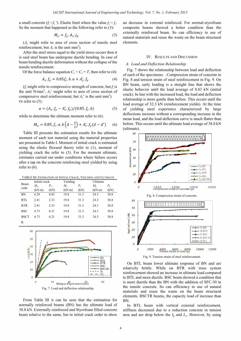
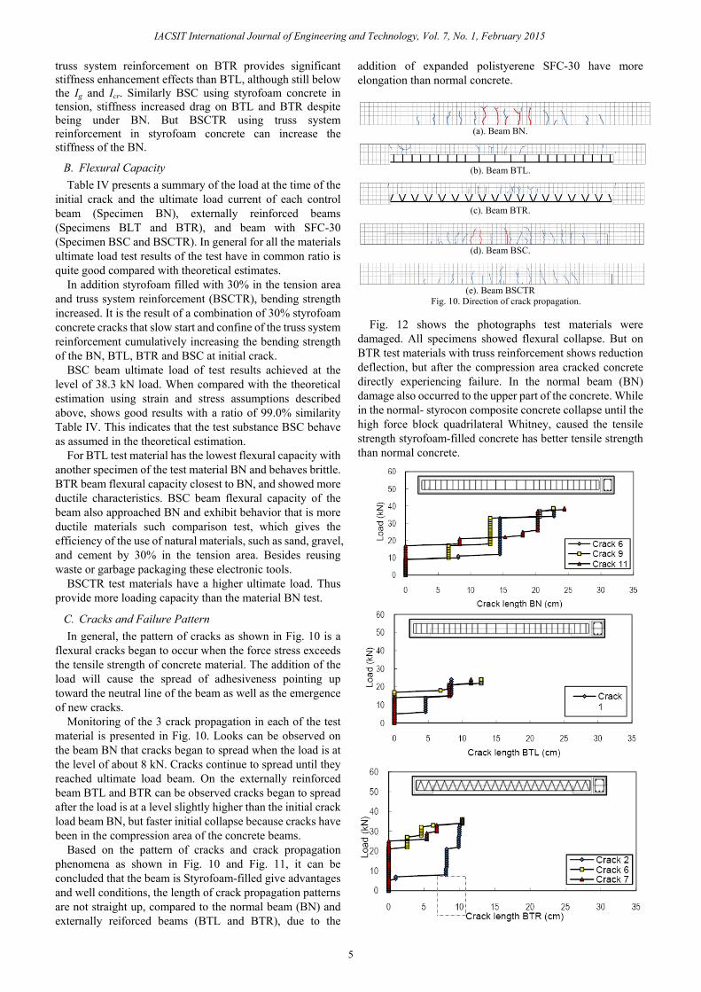
A. Load and Deflection Relationship Fig. 7 shows the relationship between load and deflection
of each of the specimens. . Compression strain of concrete in Fig. 8 and tension strain of steel reinforcement in Fig. 9. On BN beam, early loading is a straight line that shows the elastic behavior until the load average of 8.83 kN (initial crack). In line with the increased load, the load and deflection relationship is more gentle than before. This occurs until the load average of 32.3 kN (reinforcement yields). At the time of yielding steel experience characterized by large deflections increase without a corresponding increase in the mean load, and the load deflection curve is much flatter than before. This occurs until the ultimate load average of 38.8 kN (ultimate).
Fig. 8. Compression strain of concrete.
Fig. 9. Tension strain of steel reinforcement.
On BTL beam lower ultimate response of BN and are relatively brittle. While on BTR with truss system reinforcement showed an increase in ultimate load compared to BTL and more ductile. BSC beam showed a condition that is more ductile than the BN with the addition of SFC-30 in the tensile concrete. So can efficiency to use of natural materials and reuse the waste on the beam structural elements. BSCTR beams, the capacity load of increase than BN.
In BTL beam with vertical external reinforcement, stiffness decreased due to a reduction concrete in tension area and are drop below the Ig and Icr. However, by using
4
IACSIT International Journal of Engineering and Technology, Vol. 7, No. 1, February 2015
truss system reinforcement on BTR provides significant stiffness enhancement effects than BTL, although still below the Ig and Icr. Similarly BSC using styrofoam concrete in tension, stiffness increased drag on BTL and BTR despite being under BN. But BSCTR using truss system reinforcement in styrofoam concrete can increase the stiffness of the BN.
B. Flexural Capacity Table IV presents a summary of the load at the time of the
initial crack and the ultimate load current of each control beam (Specimen BN), externally reinforced beams (Specimens BLT and BTR), and beam with SFC-30 (Specimen BSC and BSCTR). In general for all the materials ultimate load test results of the test have in common ratio is quite good compared with theoretical estimates.
In addition styrofoam filled with 30% in the tension area and truss system reinforcement (BSCTR), bending strength increased. It is the result of a combination of 30% styrofoam concrete cracks that slow start and confine of the truss system reinforcement cumulatively increasing the bending strength of the BN, BTL, BTR and BSC at initial crack.
BSC beam ultimate load of test results achieved at the level of 38.3 kN load. When compared with the theoretical estimation using strain and stress assumptions described above, shows good results with a ratio of 99.0% similarity Table IV. This indicates that the test substance BSC behave as assumed in the theoretical estimation.
For BTL test material has the lowest flexural capacity with another specimen of the test material BN and behaves brittle. BTR beam flexural capacity closest to BN, and showed more ductile characteristics. BSC beam flexural capacity of the beam also approached BN and exhibit behavior that is more ductile materials such comparison test, which gives the efficiency of the use of natural materials, such as sand, gravel, and cement by 30% in the tension area. Besides reusing waste or garbage packaging these electronic tools.
BSCTR test materials have a higher ultimate load. Thus provide more loading capacity than the material BN test.
C. Cracks and Failure Pattern In general, the pattern of cracks as shown in Fig. 10 is a
flexural cracks began to occur when the force stress exceeds the tensile strength of concrete material. The addition of the load will cause the spread of adhesiveness pointing up toward the neutral line of the beam as well as the emergence of new cracks.
Monitoring of the 3 crack propagation in each of the test material is presented in Fig. 10. Looks can be observed on the beam BN that cracks began to spread when the load is at the level of about 8 kN. Cracks continue to spread until they reached ultimate load beam. On the externally reinforced beam BTL and BTR can be observed cracks began to spread after the load is at a level slightly higher than the initial crack load beam BN, but faster initial collapse because cracks have been in the compression area of the concrete beams.
Based on the pattern of cracks and crack propagation phenomena as shown in Fig. 10 and Fig. 11, it can be concluded that the beam is Styrofoam-filled give advantages and well conditions, the length of crack propagation patterns are not straight up, compared to the normal beam (BN) and externally reiforced beams (BTL and BTR), due to the
addition of expanded polistyerene SFC-30 have more elongation than normal concrete.
(a). Beam BN.
(b). Beam BTL.
(c). Beam BTR.
(d). Beam BSC.
(e). Beam BSCTR
Fig. 10. Direction of crack propagation.
Fig. 12 shows the photographs test materials were damaged. All specimens showed flexural collapse. But on BTR test materials with truss reinforcement shows reduction deflection, but after the compression area cracked concrete directly experiencing failure. In the normal beam (BN) damage also occurred to the upper part of the concrete. While in the normal- styrocon composite concrete collapse until the high force block quadrilateral Whitney, caused the tensile strength styrofoam-filled concrete has better tensile strength than normal concrete.
5
IACSIT International Journal of Engineering and Technology, Vol. 7, No. 1, February 2015

Fig. 11. Crack propagation pattern.
TABLE IV: INITIAL CRACK AND ULTIMATE LOAD OF TEST RESULT
Beam Code
Theory Experimental Ratio Exp/ Theory Pcr Pu Pcr Pu (x/BN)
(kN) (kN) (kN) (kN) exp. BN(1)
8.82 38.8
8.83 38.3 1.00 0.99
BN(2) 8.08 38.2 1.00 0.98
BN(3) 8.16 38.8 1.00 1.00
BTL(1)
2.34 38.8
2.67 24.2 0.63 0.62
BTL(2) 2.33 23.5 0.62 0.61
BTL(3) 2.33 25.7 0.66 0.66
BTR(1)
2.34 38.8
6.50 37.0 0.97 0.95
BTR(2) 4.17 34.3 0.90 0.88
BTR(3) 5.33 36.0 0.93 0.93
BSC(1)
6.21 38.8
11.30 38.5 1.01 0.99
BSC(2) 11.70 38.3 1.00 0.99
BSC(3) 11.50 38.1 0.98 0.98
BSCTR(1)
6.21 38.8
19.20 47.7 1.25 1.23
BSCTR(2) 19.70 48.5 1.27 1.25
BSCTR(3) 19.50 48.3 1.24 1.24
(a) Beam BN .
(b) Beam BTL.
(c) Beam BTR.
(d) Beam BSC.
(e) Beam BSCTR.
Fig. 12. Collapse of the test material.
V. CONCLUSION Based on the testing and analysis, it can be concluded that:
1) Relationships load and deflection in the beams with SFC-30 using truss system reinfoecement exhibits better ductility displacement than normal concrete beams.
2) Flexural capacity of composite concrete beams with SFC-30 using truss sytem reinfocement, have increase ultimate load to 48.3 kN, and the addition of expanded material on tension polistyerene styrocon area has resulted in higher elongation than normal concrete.
3) In the beams with SFC-30 using truss system reinforcement, crack propagation is taking place more slowly and smaller than the length cracks in normally reinforced concrete beams and externally reinforced concrete beam where crack propagation patterns are not straight up.
ACKNOWLEDGMENT In particular thanks are given to the Structure and
Matrerial Laboratory, Department of Civil Engineering, Hasanuddin University for their cooperation and technical advice so that the study can be done well.
REFERENCES [1] S. Jacobsen, Lecture Notes, BM3, NTNU - Norwegian University of
Science and Technology, Trondheim, Norway, 2006. [2] E. G. Nawy, Reinforced Concrete A Fundamental Approach, 3rd ed.
Prentice-Hall, Inc., 1998. [3] E. Schaumann, T. Vallée, and T. Keller, “Direct load transmission in
sandwich slabs with lightweight concrete core,” Tailor Made Concrete Structures-Walraven & Stoelhorst (eds), Taylor & Francis Group, London, UK, pp. 849-855, 2008.
[4] I. Satyarno, “Ligthweight styrofoam concrete for lighter and more ductile wall,” Journal of HAKI, vol. 7, no. 2, Jakarta, Indonesia, pp. 34-44, November 2006.
[5] I. B. D. Giri, I. K. Sudarsana, and N. M. Tutarani, “Compressive strength and modulus of elasticity concrete with addition of styrofoam (styrocon),” Scientific Journal of Civil Engineering, vol. 12, no. 1, Denpasar, Indonesia, pp.75-85, January 2008.
[6] O. G. Skjølberg and A. Hansson, “Hybrid concrete structures: Experimental testing and numerical simulation of structural element,” M.S. thesis, Department of Structural Engineering, Faculty of Engineering Science and Technology, NTNU - Norwegian University of Science and Technology, Trondheim, Norway, 2010.
[7] L. G. Nes and J. A. Overli, “Composite and hybrids: investigation of material parameters and structural performance of a concrete sandwich slab element,” in FIB (Fédération INTERNATIONALE Du BéTon) Symposium PRAQUE: Concrete Engineering for Excellence and Efficiency, Session 5-6, Praha, Czech Republic, June 8-10, 2011, pp. 1229-1232.
[8] D. C. Salmon and A Einea, “Partially composites sandwich panel deflections,” Journal of Structural Engineering, ASCE, University of Michigan, USA, vol. 121, no. 4, pp. 778-783, April 1995.
[9] V. S. Despandhe and N. A. Fleck, “Collapse of truss core sandwich beams in 3-point bending,” International Journal of Solid and Structures, Pergamon, Elsevier, UK, no. 38, pp. 6275-6305, April 30, 2001.
[10] C. Kocher, W. Watson, M. Gomez, and V. Birman, “Integrity of sandwich panels and beams with truss-reinforced cores,” Journal of Aerospace Engineering, ASCE, University of Akron, USA, vol. 15, no. 3, pp. 111-117, July 1, 2002.
[11] J. S. Liu and T. J. Lu, “Multi-objectif and multi-loading optimization of ultraweight truss material,” International Journal of Solids and Structures, Elsevier, UK, no. 41, pp. 619-635, September 24, 2004.
6
IACSIT International Journal of Engineering and Technology, Vol. 7, No. 1, February 2015

[12] M. Z. Kabir, “Structural performance of 3-D sandwich panel under
shear and flexural loading,” Journal of Scientica Iranica, vol. 12, no. 4, pp. 402-408, 2005, October 2005.
[13] J. K. Wight and J. G. MacGregor, Reinforced Concrete Mechanics and Design, 6th ed. Pearson, 2005.
Yasser is a doctoral student form Civil Engineering Department, Hasanuddin University, Makassar, Indonesia concerning on structures. He was born in Sengkang-Wajo, South Sulawesi, Indonesia on 2nd July 1977. He graduated with a bachelor of engineering (ST.) degree in 2001 and master of engineering (MT.) degree in civil engineering department from Hasanuddin University, makassar, and Indonesia in 2005. He is a chief of bridge engineers in the Department of Public Work, Konawe
Regency, and Province South-East Sulawesi, Indonesia. He previously worked as an engineering consultant in Indonesia. Later he taught in the Department of Civil Engineering in Haluoleo University, South-East Sulawesi University, Lakidende University and within Department of Public Work, Konawe Regency, Province South-East Sulawesi. He works in many Road and Bridge Project as designer, supervisor, and excecutant in Indonesia. He has published more than 7 articles related to reinforced concrete beams of structures, ecomaterial of constructions and ecotechnology of green concretes. He current and previous research interests is effect of truss system reinrocement for concrete structures. Mr. Yasser was also active in the organization of civil engineering, he was member of HAKI. He was get award of Satyalancana Karya Satya X from Indonesian Government in 2012.
Herman Parung is a professor concerning in the field of earthquake engineering and steel structures. He was born in Rantepao-Tana Toraja, South Sulawesi on July 29, 1962. In 1986 he completed the bachelor of civil engineering, at the University of Hasanuddin, Makassar, Indonesia. He obtained a master of engineering (M.Eng.) at the University of Auckland, New Zealand, in 1992. And he obtained a doctor ingenieurs (Dr. Ing.), from the Institutfuer
Stahlbau und Werkstoffmechanik, Technische Universitaet Hochschule, Darmstadt, Germany in 1998. He is the head of the Earthquake Research and Structural Engineering Laboratory, Civil Engineering Department, Hasanuddin University, Maksassar, Indonesia, as a lecturer. His major interest is design of seismic reistant buildings. He also involves in the study of precast construction and fire resistance of Steel buildings. Prof. Parung was also active in the organization of civil engineering. He is currently the head of the Indonesian Structural Engineers Association (HAKI), South Sulawesi Chapter. He was got award the best lecturers in Faculty of Engineering Hasanuddin University, 2005, from Hasanuddin University. Currently he teaches steel structure and earthquake. He current and previous research interests is castella beam of steel stuctures, comparative study composite beam-column sub-assemblage for reinforced concrete and steel structures.
Muhammad W. Tjaronge is a professor concerning in the field of construction materials technology. He was born in Makassar, South Sulawesi on May 29, 1968. In 1993 he completed bachelor's degree in civil engineering, at the University of Hasanuddin, Makassar. He obtained a master of Civil Engineering, in 1999 and obtained a doctor of civil engineering, Nagoya Institute of Technology, Japan in 2002.
He is the head of Eco-Material Research Laboratory, Civil Engineering Department, Hasanuddin University, Maksassar, Indonesia as a lecturer. He is carrying out research together as a visiting professor at Nagoya Institute of Technology, Japan in 2005. In 2012 carrying out joint research at Kyushu University, Japan for the assistance of JICA (Japan International Cooperation Agency). He was also active in writing books that relate to the concept of advance material technology of cement and core concrete. He current and previous research interests is experimental study on the microstructure and strength concrete using sea water, sand and sea portland cement composites as technology innovation.
Prof. Tjaronge is actively involved in the consultation for the application of concrete as an efficient material in a number of civil buildings that use both the structure of reinforced concrete and unreinforced concrete.
Rudy Djamaluddin is an associate professor concerning on the use of fiber reinforced composite for structural strengthening and rehabilitation. He was born in Gowa, South Sulawesi on November 8, 1970. In 1994 completed the bachelor of civil engineering, at the University of Hasanuddin, Makassar, Indonesia. He obtained his master degree in civil engineering (M.Eng.), in 2000 and pursuing his doctor of civil engineering (Dr. Eng.), from The University of
Kyushu, Japan in 2003. He is the head of the Structure and Material Laboratory, Civil Engineering
Department, Hasanuddin University, Maksassar, Indonesia, as a lecturer. He was active in research and writing books that relate to the concept of Bonding Capacity of CFRP Grid Embedded within Polymer Cement Mortar (PCM), He current and previous research interests is durability of concrete structures strengthened externally using fiber reinforced polymer (FRP) and its performances due sea environment.
Dr. Djamaluddin is member of some professional organizations such as: HAKI and PII. He has awarded by some as: research grant from JSPS on 2005 and conducted a post doctoral research from 2003 to 2005, research grant for short term research on of Kyushu University on 2012, research Grant for laboratory based research from Hasanuddin University on 2013.
7
IACSIT International Journal of Engineering and Technology, Vol. 7, No. 1, February 2015