flight airworthiness support technology - airbus home · 8/5/2015 · flight airworthiness support...
TRANSCRIPT
Airbus technical magazine
#56
FAST
August 2015
Flight Airworthiness Support Technology
02
FAS
T#54
02
FAS
T#52
02
FAS
T#52
Your Airbus technical magazine is now on tablet
iOS (iPad) & Android
The articles in this magazine appear in 2015 QTR-2 and QTR-3

03
FAS
T#56
© AIRBUS 2015All rights reserved. Proprietary document
By taking delivery of this Magazine (hereafter ‘Magazine’), you accept on behalfof your company to comply with the following. No other property rights are granted
by the delivery of this Magazine than the right to read it, for the sole purpose ofinformation. This Magazine, its content, illustrations and photos shall not be modified
nor reproduced without prior written consent of Airbus. This Magazine and thematerials it contains shall not, in whole or in part, be sold, rented, or licensed to any
third party subject to payment or not. This Magazine may contain market-sensitiveor other information that is correct at the time of going to press. This information
involves a number of factors which could change over time, affecting the true publicrepresentation. Airbus assumes no obligation to update any information contained in
this document or with respect to the information described herein. The statementsmade herein do not constitute an offer or form part of any contract. They are based on
Airbus information and are expressed in good faith but no warranty or representationis given as to their accuracy. When additional information is required, Airbus can be
contacted to provide further details. Airbus shall assume no liability forany damage in connection with the use of this Magazine and the materials it contains,
even if Airbus has been advised of the likelihood of such damages. This licenceis governed by French law and exclusive jurisdiction is given to the courts and tribunals
of Toulouse (France) without prejudice to the right of Airbus to bring proceedings forinfringement of copyright or any other intellectual property right in any other court of
competent jurisdiction. Airbus, its logo, A300, A310, A318, A319, A320, A321, A330,A340, A350, A380 and A400M are registered trademarks.
Photo copyright AirbusPhoto credits: Airbus Photographic Library, Airbus Flight Test Lab,
Airbus Group Corporate Heritage, Master Films, EXM company, Getty Images, Philippe Masclet, Hervé Gousse, Frédéric Lancelot, A. Doumenjou. A. Tchaikovski, Marc de Tienda
Publisher: Bruno PIQUET
Editor: Lucas BLUMENFELD
Design: Daren BIRCHALL
Cover: Livery painting
Photo by: A. Tchaikovski
Printer: Amadio
Authorisation for reprinting FAST magazine articles should be requested from the editor
Tel: +33 (0)5 61 93 43 88Fax: +33 (0)5 61 93 47 73
e-mail: [email protected]
FAST magazine is available on internetwww.airbus.com/support/publications
and on tablets
ISSN 1293-5476
Stealthy building panels
Head-UpDisplay system
Airline liveries
Managing airframe aerodynamic performance
Taking lithium-ion technology to new heights
FAST from the past
We’ve got it covered
04
12
18
26
32
38
39
Where you see these icons, videos or slide shows are available on the tablet app versionsof FAST magazine.
FASTFlight Airworthiness Support Technology
Airbus technical magazine
#56
02
FAS
T#52
Your Airbus technical magazine is now on tablet
iOS (iPad) & Android
04 F
AS
T#56
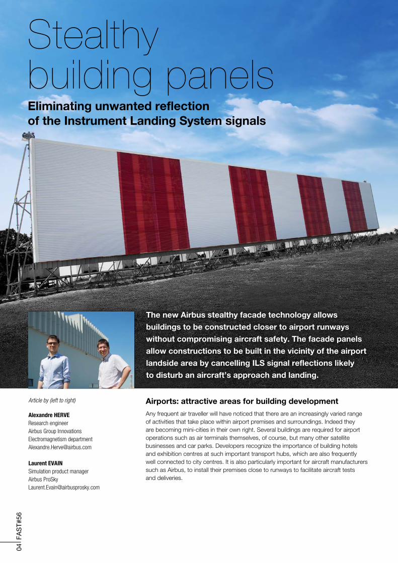
Stealthybuilding panelsEliminating unwanted reflection of the Instrument Landing System signals
Article by (left to right)
Alexandre HERVEResearch engineerAirbus Group Innovations Electromagnetism department [email protected]
Laurent EVAINSimulation product managerAirbus ProSky [email protected]
Airports: attractive areas for building developmentAny frequent air traveller will have noticed that there are an increasingly varied range of activities that take place within airport premises and surroundings. Indeed they are becoming mini-cities in their own right. Several buildings are required for airport operations such as air terminals themselves, of course, but many other satellite businesses and car parks. Developers recognize the importance of building hotels and exhibition centres at such important transport hubs, which are also frequently well connected to city centres. It is also particularly important for aircraft manufacturers such as Airbus, to install their premises close to runways to facilitate aircraft tests and deliveries.
The new Airbus stealthy facade technology allows
buildings to be constructed closer to airport runways
without compromising aircraft safety. The facade panels
allow constructions to be built in the vicinity of the airport
landside area by cancelling ILS signal reflections likely
to disturb an aircraft’s approach and landing.
05
FAS
T#56
Stealthy building panels
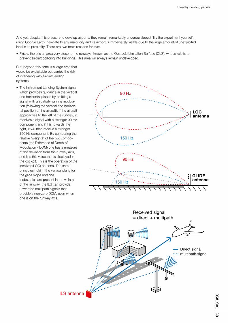
But, beyond this zone is a large area that would be exploitable but carries the risk of interfering with aircraft landing systems.
• The Instrument Landing System signal which provides guidance in the vertical and horizontal planes by emitting a signal with a spatially varying modula-tion (following the vertical and horizon-tal position of the aircraft). If the aircraft approaches to the left of the runway, it receives a signal with a stronger 90 Hz component and if it is towards the right, it will then receive a stronger 150 Hz component. By comparing the relative ‘weights’ of the two compo-nents (the Difference of Depth of Modulation - DDM) one has a measure of the deviation from the runway axis, and it is this value that is displayed in the cockpit. This is the operation of the localizer (LOC) antenna. The same principles hold in the vertical plane for the glide slope antenna. If obstacles are present in the vicinity of the runway, the ILS can provide unwanted multipath signals that provide a non-zero DDM, even when one is on the runway axis.
LOCantenna
90 Hz
90 Hz
150 Hz
150 Hz
GLIDEantenna
ILS antenna
Direct signal
Received signal= direct + multipath
multipath signal
LOCantenna
90 Hz
90 Hz
150 Hz
150 Hz
GLIDEantenna
ILS antenna
Direct signal
Received signal= direct + multipath
multipath signal
And yet, despite this pressure to develop airports, they remain remarkably underdeveloped. Try the experiment yourself using Google Earth: navigate to any major city and its airport is immediately visible due to the large amount of unexploited land in its proximity. There are two main reasons for this:
• Firstly, there is an area very close to the runways, known as the Obstacle Limitation Surface (OLS), whose role is to prevent aircraft colliding into buildings. This area will always remain undeveloped.
06
FAS
T#56
Stealthy building panels
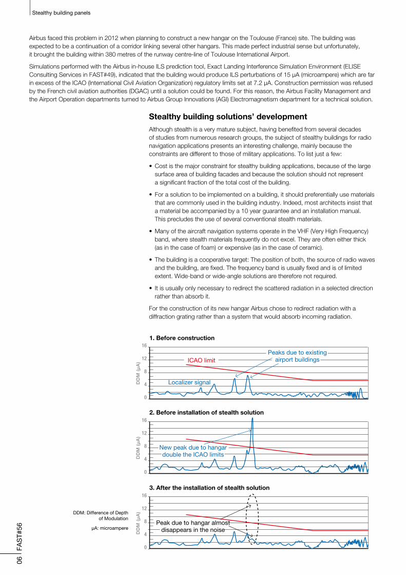
Airbus faced this problem in 2012 when planning to construct a new hangar on the Toulouse (France) site. The building was expected to be a continuation of a corridor linking several other hangars. This made perfect industrial sense but unfortunately, it brought the building within 380 metres of the runway centre-line of Toulouse International Airport.
Simulations performed with the Airbus in-house ILS prediction tool, Exact Landing Interference Simulation Environment (ELISE Consulting Services in FAST#49), indicated that the building would produce ILS perturbations of 15 μA (microampere) which are far in excess of the ICAO (International Civil Aviation Organization) regulatory limits set at 7.2 μA. Construction permission was refused by the French civil aviation authorities (DGAC) until a solution could be found. For this reason, the Airbus Facility Management and the Airport Operation departments turned to Airbus Group Innovations (AGI) Electromagnetism department for a technical solution.
Stealthy building solutions’ developmentAlthough stealth is a very mature subject, having benefited from several decades of studies from numerous research groups, the subject of stealthy buildings for radio navigation applications presents an interesting challenge, mainly because the constraints are different to those of military applications. To list just a few:
• Cost is the major constraint for stealthy building applications, because of the large surface area of building facades and because the solution should not represent a significant fraction of the total cost of the building.
• For a solution to be implemented on a building, it should preferentially use materials that are commonly used in the building industry. Indeed, most architects insist that a material be accompanied by a 10 year guarantee and an installation manual. This precludes the use of several conventional stealth materials.
• Many of the aircraft navigation systems operate in the VHF (Very High Frequency) band, where stealth materials frequently do not excel. They are often either thick (as in the case of foam) or expensive (as in the case of ceramic).
• The building is a cooperative target: The position of both, the source of radio waves and the building, are fixed. The frequency band is usually fixed and is of limited extent. Wide-band or wide-angle solutions are therefore not required.
• It is usually only necessary to redirect the scattered radiation in a selected direction rather than absorb it.
For the construction of its new hangar Airbus chose to redirect radiation with a diffraction grating rather than a system that would absorb incoming radiation.
16
12
8
4
0
DD
M (
µA
)
Localizer signal
Peaks due to existingairport buildingsICAO limit
16
12
8
4
0
2. Before installation of stealth solution
1. Before construction
DD
M (
µA
)
New peak due to hangardouble the ICAO limits
16
12
8
4
0
3. After the installation of stealth solution
DD
M (
µA
)
Peak due to hangar almostdisappears in the noise
DDM: Difference of Depth of Modulation
μA: microampere
07
FAS
T#56
Stealthy building panels
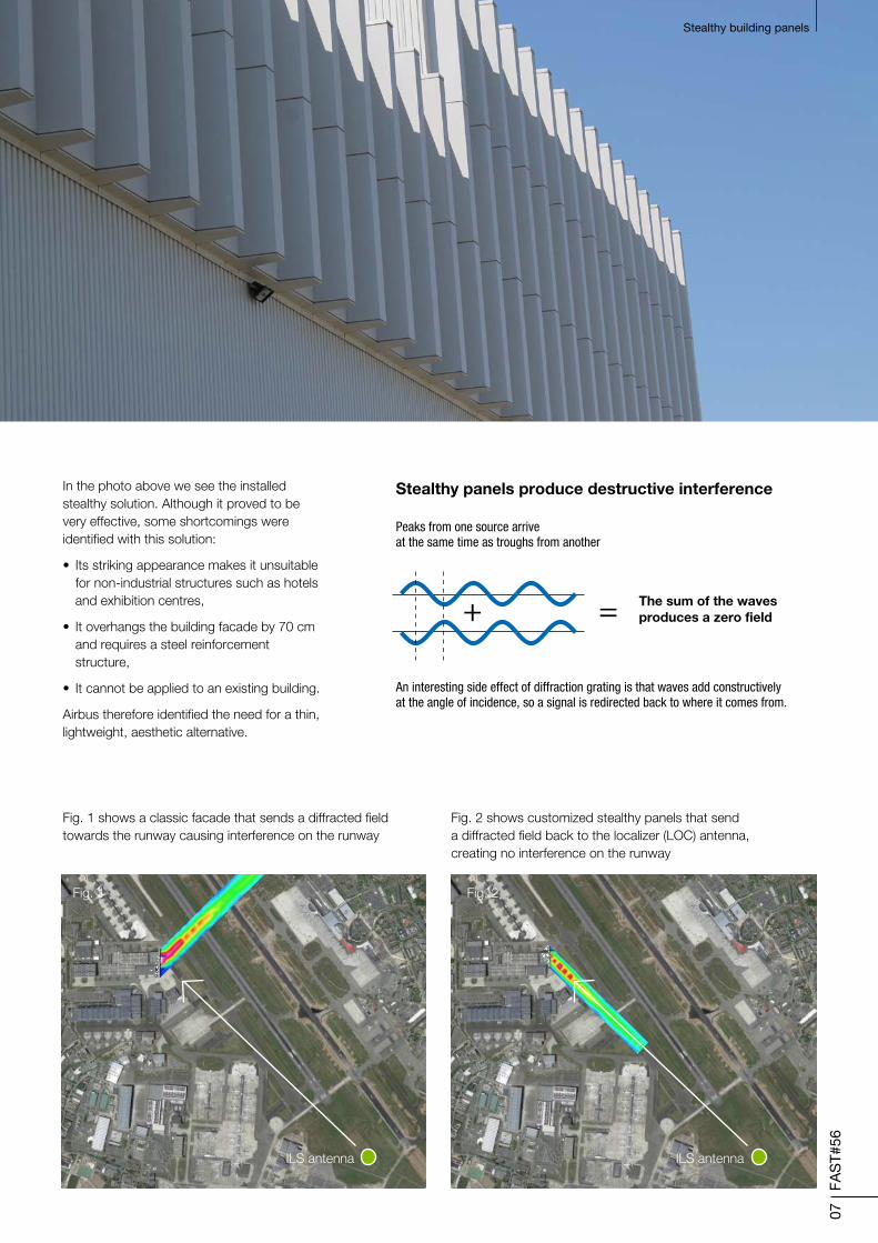
In the photo above we see the installed stealthy solution. Although it proved to be very effective, some shortcomings were identified with this solution:
• Its striking appearance makes it unsuitable for non-industrial structures such as hotels and exhibition centres,
• It overhangs the building facade by 70 cm and requires a steel reinforcement structure,
• It cannot be applied to an existing building.
Airbus therefore identified the need for a thin, lightweight, aesthetic alternative.
The sum of the wavesproduces a zero field
Stealthy panels produce destructive interference
Peaks from one source arriveat the same time as troughs from another
An interesting side effect of diffraction grating is that waves add constructivelyat the angle of incidence, so a signal is redirected back to where it comes from.
+ =
Fig. 1 shows a classic facade that sends a diffracted field towards the runway causing interference on the runway
Fig. 2 shows customized stealthy panels that send a diffracted field back to the localizer (LOC) antenna, creating no interference on the runway
Fig. 1
ILS antenna ILS antenna
Fig. 2
08
FAS
T#56
Stealthy building panels
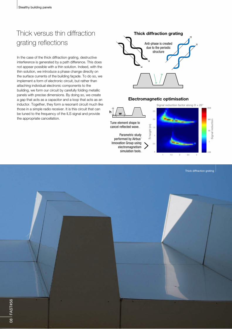
In the case of the thick diffraction grating, destructive interference is generated by a path difference. This does not appear possible with a thin solution. Indeed, with the thin solution, we introduce a phase change directly on the surface currents of the building façade. To do so, we implement a form of electronic circuit, but rather than attaching individual electronic components to the building, we form our circuit by carefully folding metallic panels with precise dimensions. By doing so, we create a gap that acts as a capacitor and a loop that acts as an inductor. Together, they form a resonant circuit much like those in a simple radio receiver. It is this circuit that can be tuned to the frequency of the ILS signal and provide the appropriate cancellation.
Thick versus thin diffraction grating reflections
Thin diffraction grating
Creating a resonant circuit
Anti-phase is createddue to the resonant
structure
C
C
h
L
R
R
L
Currents are in different directionson the resonant structures and on the surface
Design optimisation to produce exact structure
Thick diffraction grating
Electromagnetic optimisation
Anti-phase is createddue to the periodic
structure
=
w
Tune element shape tocancel reflected wave.
Parametric studyperformed by Airbus’
Innovation Group usingelectromagnetism
simulation tools.
2.5
2.0
1.5
1
0.5
0
1
2636
365
50
7
0.981.5 2 2.5 3
h he
ight
(m)
Sig
nal r
educ
tion
Signal reduction factor along Ɵ = 25°
Thick diffraction grating

09
FAS
T#56
Stealthy building panels
Through extensive simulations, we were able to establish that thin diffraction grating could produce large signal attenuations. We also came to the conclusion that heavy rain could have an effect on the solution if we did not take appropriate precautions. This is not, as one might think, because the rain creates ‘short-circuits’ in our resonant structures, but is due to the fact that when there is a large quantity of water close to a capacitor, it can change the value of its capacitance. For this reason, Airbus designed a protective screen to preserve a distance between the capacitor and the rain-layer.
Before trying this new technology on an existing building, Airbus decided that it would be better to perform tests on a full-scale prototype. To do so, Airbus collaborated with the French civil aviation authorities (DGAC) who possess a fully functioning ILS antenna at the small aerodrome: Cahors-Lalbenque (France). This technology, initially imagined by the Electromagnetism department of Airbus Group Innovations, was validated in 2014 on a prototype at the Cahors airfield, thanks to the support of the Airbus Business Nursery (now named Airbus BizLab), and is currently being commercialized by Airbus through its 100% ATM subsidiary: Airbus ProSky.
Thin diffraction grating
Creating a resonant circuit
Anti-phase is createddue to the resonant
structure
C
C
h
L
R
R
L
Currents are in different directionson the resonant structures and on the surface
Design optimisation to produce exact structure
Thick diffraction grating
Electromagnetic optimisation
Anti-phase is createddue to the periodic
structure
=
w
Tune element shape tocancel reflected wave.
Parametric studyperformed by Airbus’
Innovation Group usingelectromagnetism
simulation tools.
2.5
2.0
1.5
1
0.5
0
1
2636
365
50
7
0.981.5 2 2.5 3
h he
ight
(m)
Sig
nal r
educ
tion
Signal reduction factor along Ɵ = 25°
Thin diffraction grating
150
100
50
0
-50
-100
-150
0.4
0.3
0.2
0.1
0.0
108.0 108.5 109.0 109.5 110.0 110.5 111.0 111.5 112.0
150
100
50
0
-50
-100
-150
150
100
50
0
-50
-100
-150
300 400 500
Position along the runway (m)
Pe
rtu
rba
tio
n (
µA
)
Fra
ctio
nal r
educ
tion
Frequency (MHz)
600 700
150
100
50
0
-50
-100
-150
Interference still reduced by 90 %
Wet diffraction gratingcompared to normal facade
Dry diffraction gratingcompared to normal facade
Normal facade
No facade
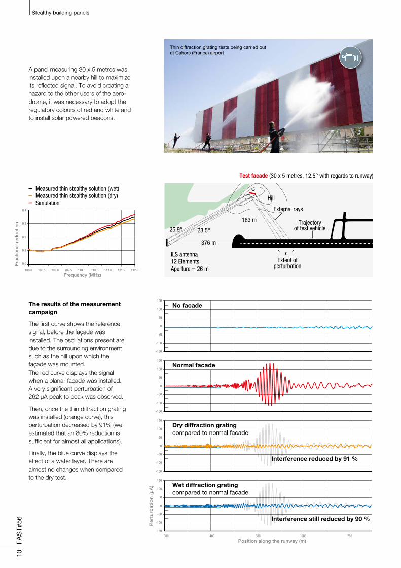
Measured thin stealthy solution (wet)Measured thin stealthy solution (dry)Simulation
Test facade (30 x 5 metres, 12.5° with regards to runway)
Woodedarea
ILS antenna12 ElementsAperture = 26 m
25.9° 23.5°
376 m
183 m
Hill
External rays
Trajectoryof test vehicle
Extent ofperturbation
Interference reduced by 91 %
10
FAS
T#56
Stealthy building panels
A panel measuring 30 x 5 metres was installed upon a nearby hill to maximize its reflected signal. To avoid creating a hazard to the other users of the aero-drome, it was necessary to adopt the regulatory colours of red and white and to install solar powered beacons.
The results of the measurement campaign
The first curve shows the reference signal, before the façade was installed. The oscillations present are due to the surrounding environment such as the hill upon which the façade was mounted. The red curve displays the signal when a planar façade was installed. A very significant perturbation of 262 μA peak to peak was observed.
Then, once the thin diffraction grating was installed (orange curve), this perturbation decreased by 91% (we estimated that an 80% reduction is sufficient for almost all applications).
Finally, the blue curve displays the effect of a water layer. There are almost no changes when compared to the dry test.
Thin diffraction grating tests being carried out at Cahors (France) airport
C O N C L U S I O N
Airbus’ stealthy panels proved to be efficient in the reduction of unwanted disturbances of Instrument Landing System signals due to building facades. The thinner of the two technologies suits installation onto existing buildings as well as new projects. These new panels could resolve known cases of spurious reflections that disturb ILS and render parcels of land in proximity to runways constructible.
11
FAS
T#56
Stealthy building panels
Stealthy facades
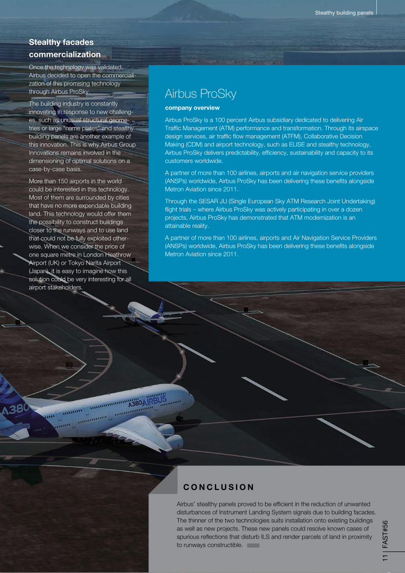
commercializationOnce the technology was validated, Airbus decided to open the commerciali-zation of this promising technology through Airbus ProSky.
The building industry is constantly innovating in response to new challeng-es, such as unusual structural geome-tries or large “name plates” and stealthy building panels are another example of this innovation. This is why Airbus Group Innovations remains involved in the dimensioning of optimal solutions on a case-by-case basis.
More than 150 airports in the world could be interested in this technology. Most of them are surrounded by cities that have no more expendable building land. This technology would offer them the possibility to construct buildings closer to the runways and to use land that could not be fully exploited other-wise. When we consider the price of one square metre in London Heathrow Airport (UK) or Tokyo Narita Airport (Japan), it is easy to imagine how this solution could be very interesting for all airport stakeholders.
Airbus ProSky company overview
Airbus ProSky is a 100 percent Airbus subsidiary dedicated to delivering Air Traffic Management (ATM) performance and transformation. Through its airspace design services, air traffic flow management (ATFM), Collaborative Decision Making (CDM) and airport technology, such as ELISE and stealthy technology, Airbus ProSky delivers predictability, efficiency, sustainability and capacity to its customers worldwide.
A partner of more than 100 airlines, airports and air navigation service providers (ANSPs) worldwide, Airbus ProSky has been delivering these benefits alongside Metron Aviation since 2011.
Through the SESAR JU (Single European Sky ATM Research Joint Undertaking) flight trials – where Airbus ProSky was actively participating in over a dozen projects, Airbus ProSky has demonstrated that ATM modernization is an attainable reality.
A partner of more than 100 airlines, airports and Air Navigation Service Providers (ANSPs) worldwide, Airbus ProSky has been delivering these benefits alongside Metron Aviation since 2011.
12
FAS
T#56
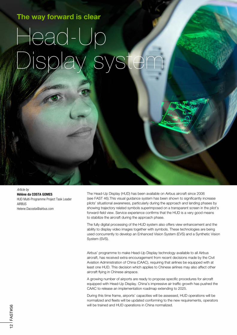
Article by Hélène da COSTA GOMESHUD Multi-Programme Project Task [email protected]
Head-Up Display system
The way forward is clear
Airbus’ programme to make Head-Up Display technology available to all Airbus aircraft, has received extra encouragement from recent decisions made by the Civil Aviation Administration of China (CAAC), requiring that airlines be equipped with at least one HUD. This decision which applies to Chinese airlines may also affect other aircraft flying in Chinese airspace.
A growing number of airports are ready to propose specific procedures for aircraft equipped with Head-Up Display. China’s impressive air traffic growth has pushed the CAAC to release an implementation roadmap extending to 2025.
During this time frame, airports’ capacities will be assessed, HUD operations will be normalized and fleets will be updated conforming to the new requirements, operators will be trained and HUD operations in China normalized.
The Head-Up Display (HUD) has been available on Airbus aircraft since 2006 (see FAST 46).This visual guidance system has been shown to significantly increase pilots’ situational awareness, particularly during the approach and landing phases by showing trajectory related symbols superimposed on a transparent screen in the pilot’s forward-field view. Service experience confirms that the HUD is a very good means to stabilize the aircraft during the approach phase.
The fully digital processing of the HUD system also offers view enhancement and the ability to display video images together with symbols. These technologies are being used concurrently to develop an Enhanced Vision System (EVS) and a Synthetic Vision System (SVS).
13
FAS
T#56
Head-Up Display
The evolving Airbus HUD offerGoing one step further than the CAAC’s roadmap, Airbus is gradually incorporating dual HUD into all Airbus aircraft as part of their ‘symmetrical cockpit philosophy.
Beyond this Airbus reviewed the HUD policy to include the following improvements:
A320 Family
A new HUD standard (L5) was certified in February 2015. This standard upgrades the system to restore compatibility with the latest developments in functions such as:
• Runway Overrun Prevention System (ROPS - see FAST #55)
• Required Navigation Performance Authorisation Required (RNP AR) step 3 (down to 0.1 Nautical Miles)
• Auto-Pilot/Flight Director Traffic alert and Collision Avoidance System (AP/FD TCAS)
• Advisory runway ahead
• Soft go-around
• Reversible Back-Up Speed Scale (BUSS)
Moreover, this standard enables the integration of a dual HUD configuration on single aisle family aircraft and proposes symbology improvements. The dual HUD configura-tion has been proposed on single-aisle aircraft (except A321) since March 2015.
By the beginning of 2016, the HUD offer will be extended to the A321 model.
A330 Family
Development was launched in 2013 to certify dual HUD on long range family aircraft. The long range HUD standard will be based on the latest certified single-aisle standard and proposes the latest functionalities to keep the highest symbology and operations’ commonality throughout Airbus’ fleet.
A350 Family
HUD was part of the cockpit development from the very beginning; so the HUD is more integrated in the overhead panel. Space provisions have been enlarged to provide best head-clearance for pilots. The system has been designed with a new Liquid-Crystal Display (LCD) technology projector with Light-Emitting Diode (LED) backlights. HUD software is integrated in the display system.
The A350 already proposes the dual HUD as an option since Entry-Into-Service.
A380
The A380 proposes a dual HUD option in the catalogue. A new standard is being developed to propose the latest display functionalities.
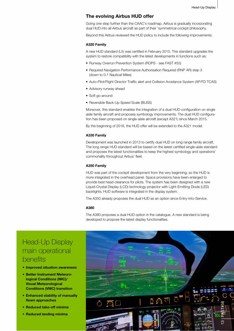
Head-Up Display main operational benefits• Improved situation awareness
• Better Instrument Meteoro- logical Conditions (IMC)/ Visual Meteorological Conditions (VMC) transition
• Enhanced stability of manually flown approaches
• Reduced take-off minima
• Reduced landing minima
14
FAS
T#56
Head-Up Display
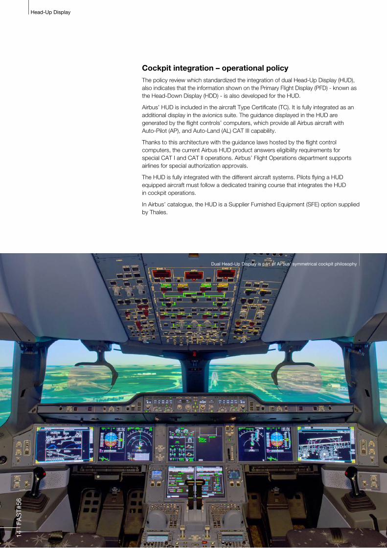
Cockpit integration – operational policyThe policy review which standardized the integration of dual Head-Up Display (HUD), also indicates that the information shown on the Primary Flight Display (PFD) - known as the Head-Down Display (HDD) - is also developed for the HUD.
Airbus’ HUD is included in the aircraft Type Certificate (TC). It is fully integrated as an additional display in the avionics suite. The guidance displayed in the HUD are generated by the flight controls’ computers, which provide all Airbus aircraft with Auto-Pilot (AP), and Auto-Land (AL) CAT III capability.
Thanks to this architecture with the guidance laws hosted by the flight control computers, the current Airbus HUD product answers eligibility requirements for special CAT I and CAT II operations. Airbus’ Flight Operations department supports airlines for special authorization approvals.
The HUD is fully integrated with the different aircraft systems. Pilots flying a HUD equipped aircraft must follow a dedicated training course that integrates the HUD in cockpit operations.
In Airbus’ catalogue, the HUD is a Supplier Furnished Equipment (SFE) option supplied by Thales.
Dual Head-Up Display is part of Airbus’ symmetrical cockpit philosophy

15
FAS
T#56
Head-Up Display
Airports are categorized CAT I, CAT II, CAT III, Special CAT I and Special CAT II, based on their Instrument Landing System.
ICAO (International Civil Aviation Organization) classifies ILS approaches as being in one of the following categories:
1,600 feet(800 metres) or 1,200 feet in Canada
N/A
N/A
N/A
N/A
Either visibility not less than 2,400 feet (800 metres) or a runway visual range(RVR) not less than 1,800 feet (550 metres) on runway with touchdown zone and centerline lighting
ICAO and FAA: 1,150 feet (350 metres)or JAA: 980 feet (300 metres)
As of 2012 this category is not yet in operation anywhere in the world as it requires guidance to taxi in zero visibility as well. Category IIIc is not mentioned in EU-OPS.
1,800 feet (550 metres) (1,200 feet is approved at some airports), increased to 1,600 feet (800 metres)for single crew operations
1,200 feet (370 metres)
700 feet (210 metres)
150 feet (46 metres)
No RVR
200 feet (61 metres)
100 feet (30 metres)
No DH
No DH
No DH
CAT I
CAT II
CAT IIIa
CAT IIIb
CAT IIIc
NotesApproachcategory
Decision Height (DH)or alert height(minimum above runwaythreshold or touchdown zone)
Runway VisualRange (RVR)
Visibilityminimum
Special CAT I operation• Standard instrument approach procedure
using the Instrument Landing System (ILS) flown to a DH 150 feet and RVR 1400 feet (nominal CAT I = DH 200 feet / RVR 1800 feet)
• Requires operational approval from flight standards including pilot training
• Must be flown with a HUD down to the DH
Special CAT II operation• Standard instrument approach procedure using ILS
flown to a DH 100 feet and RVR 1200 feet
• Differs from CAT II because it: - Allows reduced ground lighting infrastructure
- Can be flown with Medium Intensity Approach Lighting System (MIALS) with runway alignment indicator lights (MALSR)
- Does not require runway centreline or runway touchdown lighting.
• Requires operational approval from flight standards including pilot training
• Must be flown with:
- Automatic landing
- Or a HUD providing guidance to touch-down
Head-Up Display
Innovation catalyserThe widespread use and appreciation of HUD by pilots has led to new concepts in information display. The HUD guidance is based on trajectory and energy manage-ment while the HDD (Head-Down Display) traditionally provides pitch and thrust data. These differences in flying reference brought a general reflection on the possibility to extend HUD symbols on HDD displays. The operational concept and the technical feasibility are being assessed in Airbus’ design offices with the objective to have a mock-up this year that will be evaluated by test pilots with the support of operation and human factor experts. This “enhanced Primary Flight Display” (PFD) will ease HUD to HDD transitions.
In the same mind-set that instigated the CAAC’s directive for Chinese airspace, there are several projects to implement new display features to ease guidance during take-off and landing manoeuvres. As a see-through display technology, the HUD enables augmented reality such as synthetic vision, enhanced vision, etc., but also a lot of possible conformal symbols to improve situation awareness. Airbus is assessing the feasibility of new symbols.
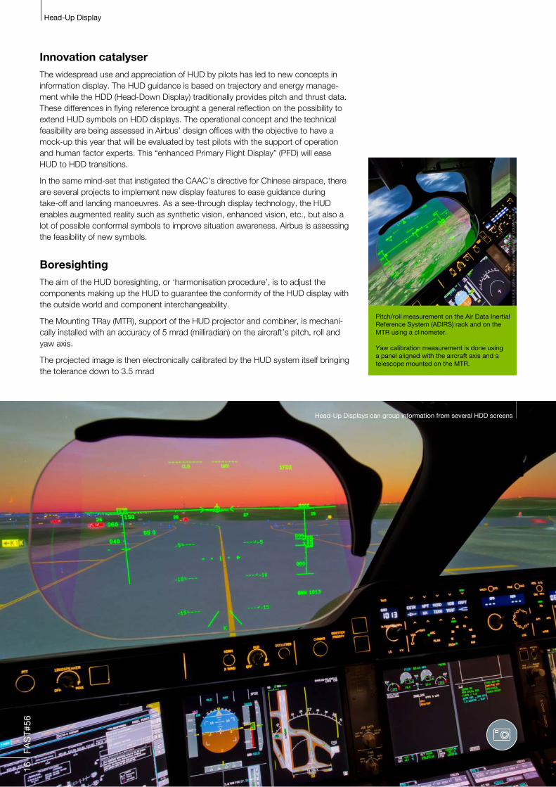
BoresightingThe aim of the HUD boresighting, or ‘harmonisation procedure’, is to adjust the components making up the HUD to guarantee the conformity of the HUD display with the outside world and component interchangeability.
The Mounting TRay (MTR), support of the HUD projector and combiner, is mechani-cally installed with an accuracy of 5 mrad (milliradian) on the aircraft’s pitch, roll and yaw axis.
The projected image is then electronically calibrated by the HUD system itself bringing the tolerance down to 3.5 mrad
16
FAS
T#56
Pitch/roll measurement on the Air Data Inertial Reference System (ADIRS) rack and on the MTR using a clinometer.
Yaw calibration measurement is done using a panel aligned with the aircraft axis and a telescope mounted on the MTR.
Head-Up Displays can group information from several HDD screens
C O N C L U S I O N
Head-Up display is an evolving technology that provides pilots with the ability to read flight control data projected onto a transparent screen. The main operational benefit is situational awareness due to the exact alignment of guiding information with the pilot’s forward-field view.
Recent air traffic constraints coupled with a symmetrical cockpit philosophy have accelerated Airbus’ policy to integrate dual Head-Up Displays into all of its manufactured aircraft before 2018.
Head-Up Display has a huge potential. Two technologies that are currently being developed are the Enhanced Vision System (EVS) and the Sythetic Vision System (SVS), that will allow pilots to see runways in otherwise extremely poor visibility conditions.
Head-Up display retrofits are available for all A320 Family aircraft starting from MSN 3000.
Head-Up Display
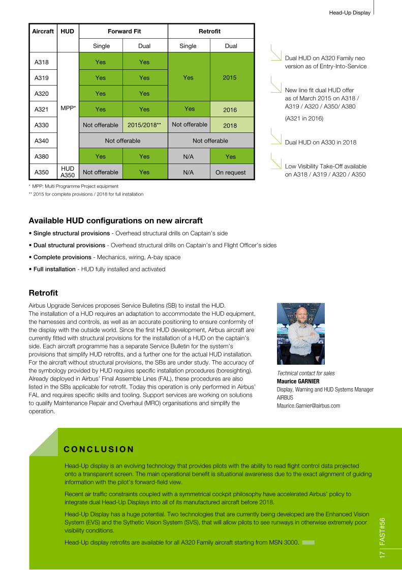
RetrofitAirbus Upgrade Services proposes Service Bulletins (SB) to install the HUD. The installation of a HUD requires an adaptation to accommodate the HUD equipment, the harnesses and controls, as well as an accurate positioning to ensure conformity of the display with the outside world. Since the first HUD development, Airbus aircraft are currently fitted with structural provisions for the installation of a HUD on the captain’s side. Each aircraft programme has a separate Service Bulletin for the system’s provisions that simplify HUD retrofits, and a further one for the actual HUD installation. For the aircraft without structural provisions, the SBs are under study. The accuracy of the symbology provided by HUD requires specific installation procedures (boresighting). Already deployed in Airbus’ Final Assemble Lines (FAL), these procedures are also listed in the SBs applicable for retrofit. Today this operation is only performed in Airbus’ FAL and requires specific skills and tooling. Support services are working on solutions to qualify Maintenance Repair and Overhaul (MRO) organisations and simplify the operation.
Available HUD configurations on new aircraft• Single structural provisions - Overhead structural drills on Captain’s side
• Dual structural provisions - Overhead structural drills on Captain’s and Flight Officer’s sides
• Complete provisions - Mechanics, wiring, A-bay space
• Full installation - HUD fully installed and activated
17
FAS
T#56
Aircraft
Forward Fit Retrofit
Single SingleDual Dual
HUD
MPP*
HUDA350
A318
A319
A320
A321
A330
A340
A380
A350
Yes 2015
Yes
Not offerable
2016
2018
Yes
Yes
Yes
Yes
2015/2018**
Yes
Yes
N/A
N/A
Yes
Yes
Yes
Yes
Not offerable
Yes
Not offerable
Yes
On request
Not offerable Not offerable
Technical contact for salesMaurice GARNIERDisplay, Warning and HUD Systems [email protected]
Dual HUD on A320 Family neo version as of Entry-Into-Service
New line fit dual HUD offer as of March 2015 on A318 / A319 / A320 / A350/ A380
(A321 in 2016)
Dual HUD on A330 in 2018
Low Visibility Take-Off available on A318 / A319 / A320 / A350
* MPP: Multi Programme Project equipment
** 2015 for complete provisions / 2018 for full installation

18
FAS
T#56
Airline liveries
Article byPascal CORNET Fleet Manager Embodiment [email protected]
In today’s competitive market, it has never been more
important to have a memorable and attractive brand,
and by far the largest visual application of an airline’s
brand is the livery of its aircraft.Depending on brand orientation, an airline may simply wish this external decoration to be a strict interpretation of their company’s visual identity, or maybe a fun, colourful, exotic design that represents their warm corporate values or indeed a particularly eye-catching design for a short-term promotional campaign.
The variations of aircraft livery are as endless as the creativity and inventiveness of airlines. But whatever the branding strategy an airline may choose, the major considerations - which are all directly associated with cost - are the time and expertise needed in a paint shop to realize these ‘works of art’.
Airbus’ innovation to reduce livery painting time
19
FAS
T#56
Airline liveries
Until very recently, the multi-step plotting and masking involved in aircraft decoration was achieved by highly experienced paint shop technicians, often working by eye. Complicated designs took several times longer to prepare than to actually paint, requiring weeks of aircraft downtime. Airlines clearly needed a better and more adaptable solution.
Airbus Painting and Livery services worked with airlines to define their priorities:
• A fast and precise plotting of 2D designs onto a 3D surface
• Tools that allow a repeatable process
• An attainable quality identical to that of Airbus’ final assembly lines in any paint shop
• An adaptable system for all Airbus aircraft
Airbus has not only invented, patented and put in place a modular set of turnkey services that now allow all these requirements, but still undertakes - if required - the management of working parties at selected Maintenance Repair and Overhaul (MRO) organisations. In its role as the Original Equipment Manufacturer (OEM), Airbus provides the certifying documents associated with a new livery.
Airbus’ innovation to reduce livery painting time
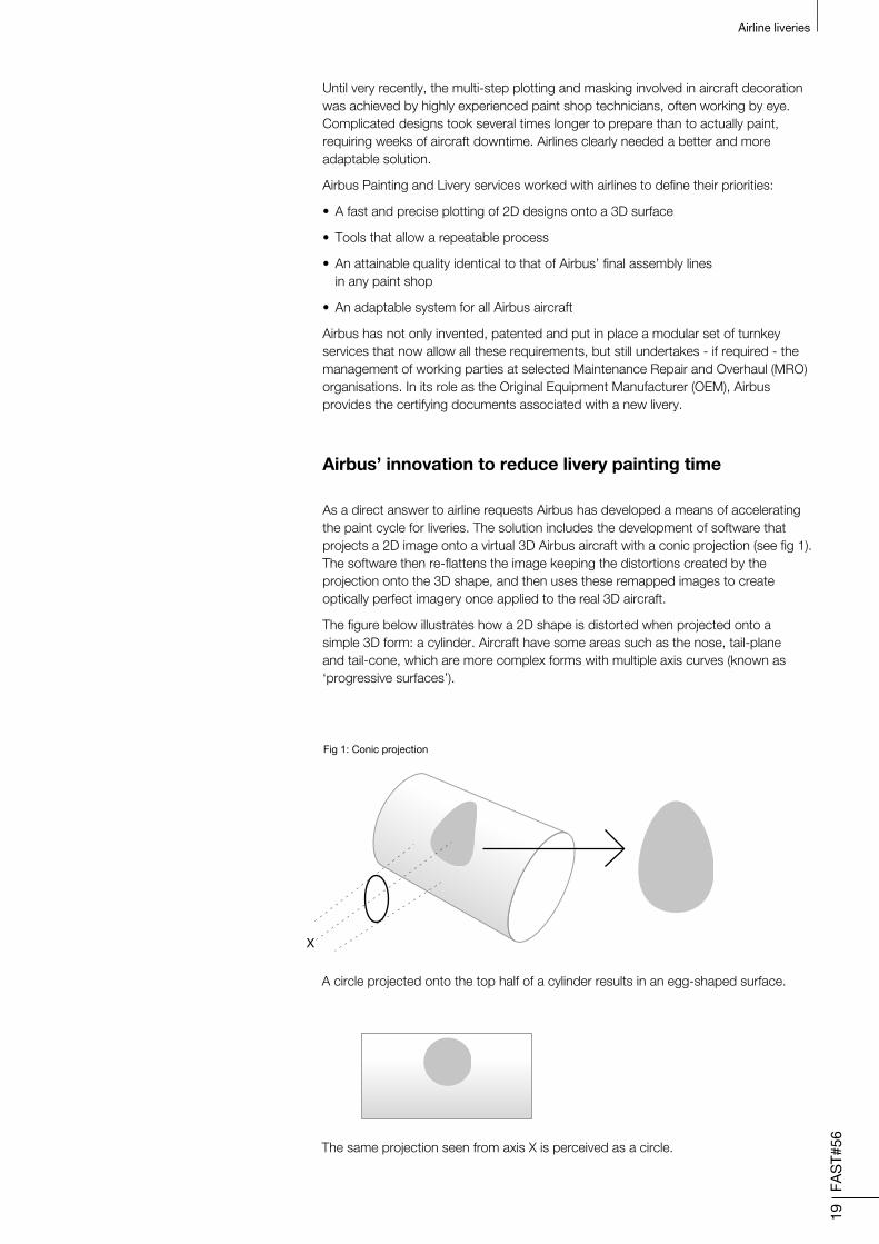
As a direct answer to airline requests Airbus has developed a means of accelerating the paint cycle for liveries. The solution includes the development of software that projects a 2D image onto a virtual 3D Airbus aircraft with a conic projection (see fig 1). The software then re-flattens the image keeping the distortions created by the projection onto the 3D shape, and then uses these remapped images to create optically perfect imagery once applied to the real 3D aircraft.
The figure below illustrates how a 2D shape is distorted when projected onto a simple 3D form: a cylinder. Aircraft have some areas such as the nose, tail-plane and tail-cone, which are more complex forms with multiple axis curves (known as ‘progressive surfaces’).
A circle projected onto the top half of a cylinder results in an egg-shaped surface.
The same projection seen from axis X is perceived as a circle.
X
Fig 1: Conic projection
20
FAS
T#56
Airline liveries
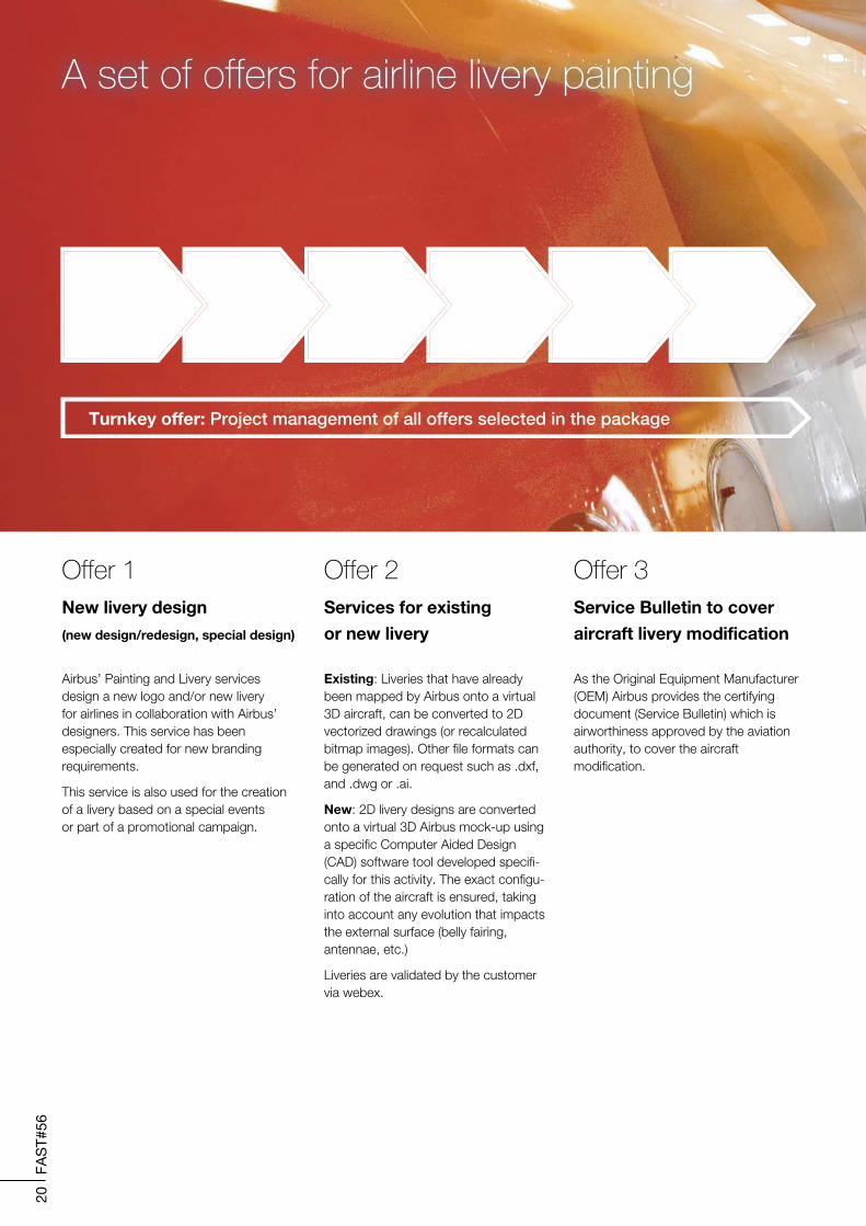
Offer 1New livery design
(new design/redesign, special design)
Airbus’ Painting and Livery services design a new logo and/or new livery for airlines in collaboration with Airbus’ designers. This service has been especially created for new branding requirements.
This service is also used for the creation of a livery based on a special events or part of a promotional campaign.
Offer 2Services for existing
or new livery
Existing: Liveries that have already been mapped by Airbus onto a virtual 3D aircraft, can be converted to 2D vectorized drawings (or recalculated bitmap images). Other file formats can be generated on request such as .dxf, and .dwg or .ai.
New: 2D livery designs are converted onto a virtual 3D Airbus mock-up using a specific Computer Aided Design (CAD) software tool developed specifi-cally for this activity. The exact configu-ration of the aircraft is ensured, taking into account any evolution that impacts the external surface (belly fairing, antennae, etc.)
Liveries are validated by the customer via webex.
Offer 3 Service Bulletin to cover
aircraft livery modification
As the Original Equipment Manufacturer (OEM) Airbus provides the certifying document (Service Bulletin) which is airworthiness approved by the aviation authority, to cover the aircraft modification.
A set of offers for airline livery painting
1New livery design
Turnkey offer: Project management of all offers selected in the package
2Vectorizeddrawings
3ServiceBulletin
4Mylar& adhesive stencils
5Livery painting/applying
6Paintconsulting
21
FAS
T#56
Airline liveries
Offer 5Livery painting/applying
management
Airbus’ Paint and Livery department proposes its services in a project management role.
Ideally placed, Airbus can oversee livery projects, integrate its livery offers (1 to 4) if required, and organize working parties at selected Part-145 maintenance/repair stations around the world.
Offer 6Paint consulting
Airbus also proposes its services for kits application and paint process optimization with specialists from Airbus’ production paint shop.
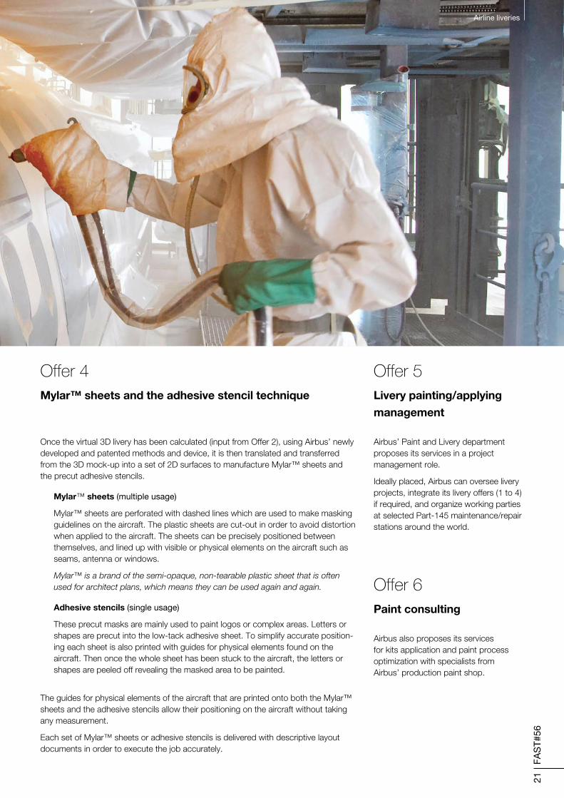
Offer 4
Mylar™ sheets and the adhesive stencil technique
Once the virtual 3D livery has been calculated (input from Offer 2), using Airbus’ newly developed and patented methods and device, it is then translated and transferred from the 3D mock-up into a set of 2D surfaces to manufacture Mylar™ sheets and the precut adhesive stencils.
Mylar™ sheets (multiple usage)
Mylar™ sheets are perforated with dashed lines which are used to make masking guidelines on the aircraft. The plastic sheets are cut-out in order to avoid distortion when applied to the aircraft. The sheets can be precisely positioned between themselves, and lined up with visible or physical elements on the aircraft such as seams, antenna or windows.
Mylar™ is a brand of the semi-opaque, non-tearable plastic sheet that is often used for architect plans, which means they can be used again and again.
Adhesive stencils (single usage)
These precut masks are mainly used to paint logos or complex areas. Letters or shapes are precut into the low-tack adhesive sheet. To simplify accurate position-ing each sheet is also printed with guides for physical elements found on the aircraft. Then once the whole sheet has been stuck to the aircraft, the letters or shapes are peeled off revealing the masked area to be painted.
The guides for physical elements of the aircraft that are printed onto both the Mylar™ sheets and the adhesive stencils allow their positioning on the aircraft without taking any measurement.
Each set of Mylar™ sheets or adhesive stencils is delivered with descriptive layout documents in order to execute the job accurately.
Airline liveries
22
FAS
T#56
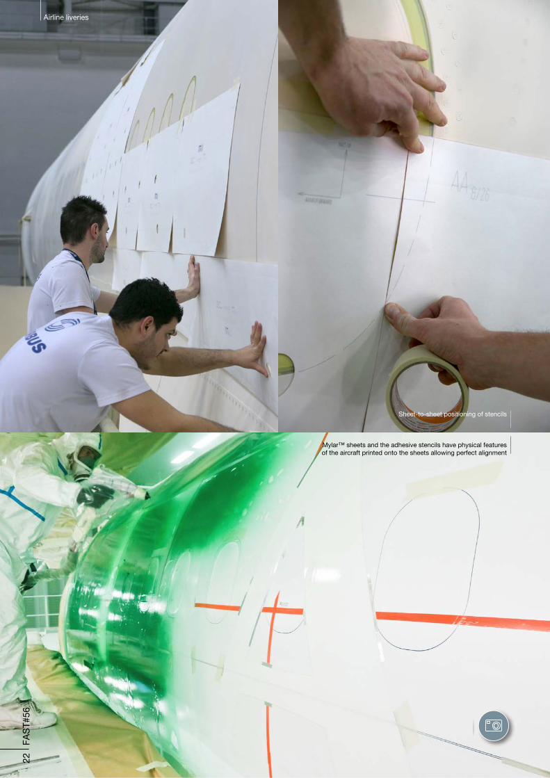
Sheet-to-sheet positioning of stencils
Mylar™ sheets and the adhesive stencils have physical featuresof the aircraft printed onto the sheets allowing perfect alignment
Airline liveries
23
FAS
T#56
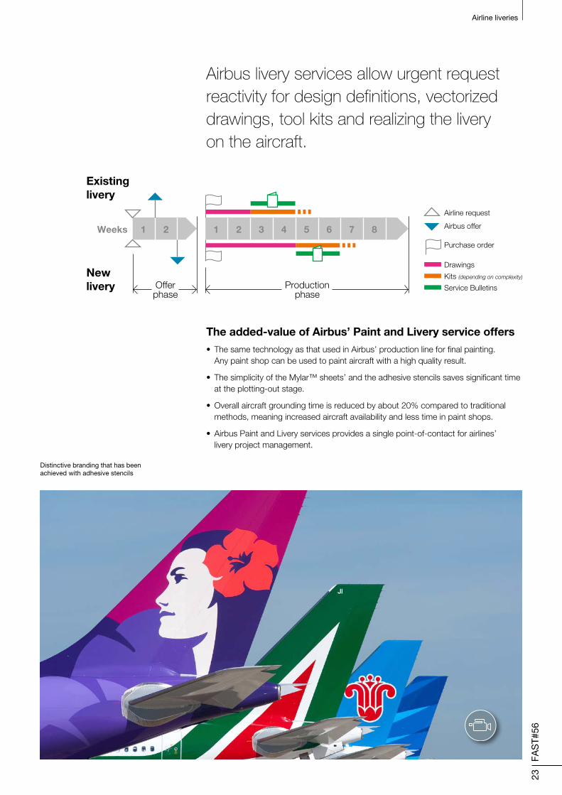
The added-value of Airbus’ Paint and Livery service offers• The same technology as that used in Airbus’ production line for final painting.
Any paint shop can be used to paint aircraft with a high quality result.
• The simplicity of the Mylar™ sheets’ and the adhesive stencils saves significant time at the plotting-out stage.
• Overall aircraft grounding time is reduced by about 20% compared to traditional methods, meaning increased aircraft availability and less time in paint shops.
• Airbus Paint and Livery services provides a single point-of-contact for airlines’ livery project management.
Airbus livery services allow urgent request reactivity for design definitions, vectorized drawings, tool kits and realizing the livery on the aircraft.
1 2 3 4 5 6 7 8Weeks 1 2
Existinglivery
Newlivery Offer
phase
Airline request
Airbus offer
Purchase order
Drawings
Productionphase
Kits (depending on complexity)
Service Bulletins
Airline liveries
Distinctive branding that has beenachieved with adhesive stencils
Airline liveries24
FA
ST#
56
Airline liveries
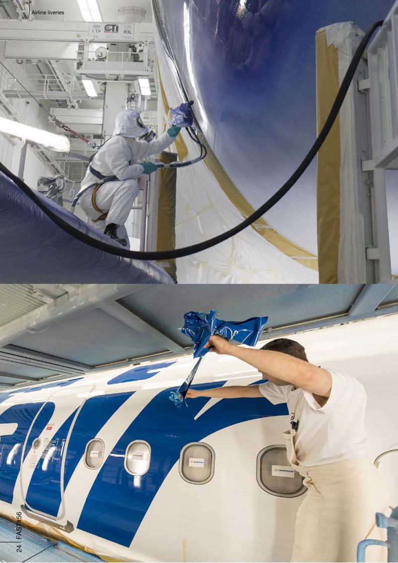
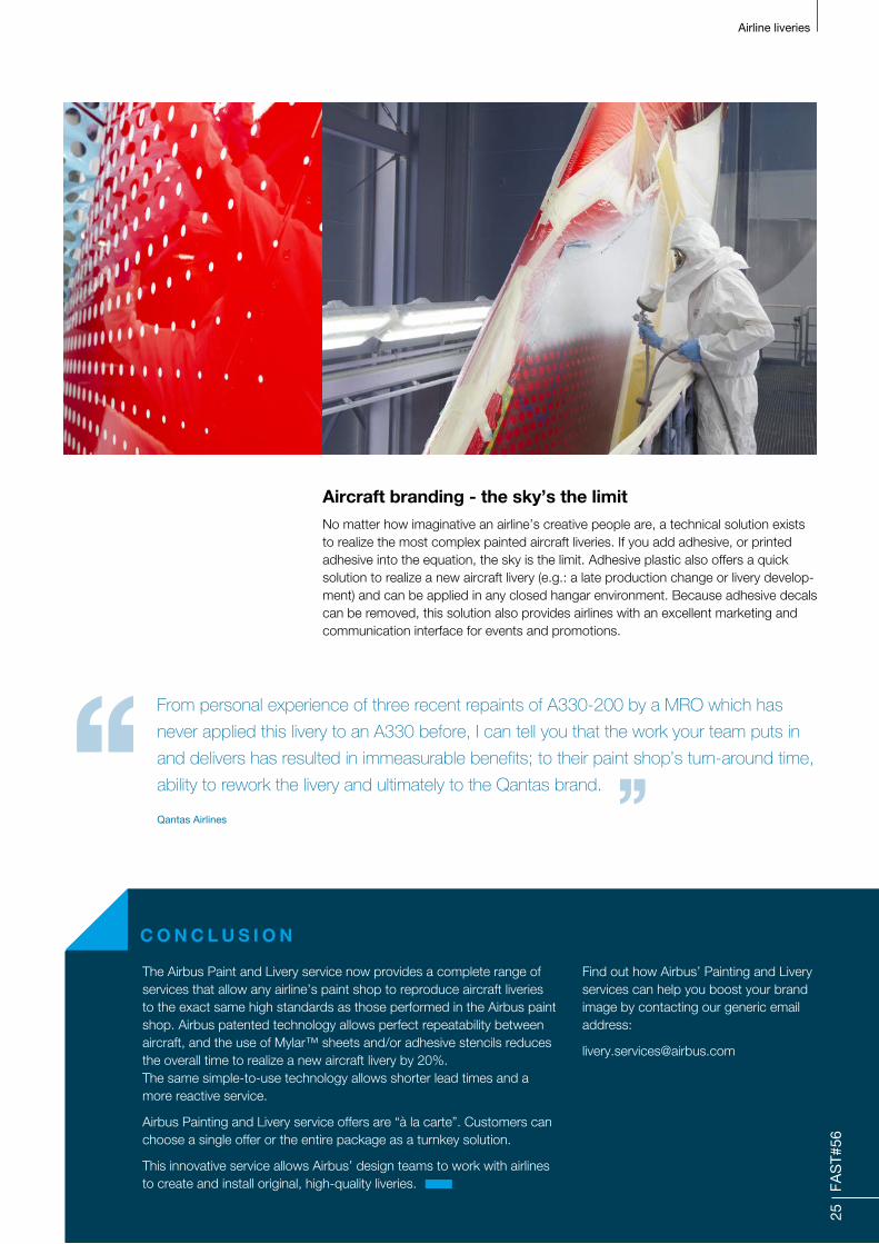
Aircraft branding - the sky’s the limitNo matter how imaginative an airline’s creative people are, a technical solution exists to realize the most complex painted aircraft liveries. If you add adhesive, or printed adhesive into the equation, the sky is the limit. Adhesive plastic also offers a quick solution to realize a new aircraft livery (e.g.: a late production change or livery develop-ment) and can be applied in any closed hangar environment. Because adhesive decals can be removed, this solution also provides airlines with an excellent marketing and communication interface for events and promotions.
From personal experience of three recent repaints of A330-200 by a MRO which has
never applied this livery to an A330 before, I can tell you that the work your team puts in
and delivers has resulted in immeasurable benefits; to their paint shop’s turn-around time,
ability to rework the livery and ultimately to the Qantas brand.
C O N C L U S I O N
Find out how Airbus’ Painting and Livery services can help you boost your brand image by contacting our generic email address:
Qantas Airlines
The Airbus Paint and Livery service now provides a complete range of services that allow any airline’s paint shop to reproduce aircraft liveries to the exact same high standards as those performed in the Airbus paint shop. Airbus patented technology allows perfect repeatability between aircraft, and the use of Mylar™ sheets and/or adhesive stencils reduces the overall time to realize a new aircraft livery by 20%. The same simple-to-use technology allows shorter lead times and a more reactive service.
Airbus Painting and Livery service offers are “à la carte”. Customers can choose a single offer or the entire package as a turnkey solution.
This innovative service allows Airbus’ design teams to work with airlines to create and install original, high-quality liveries.
25
FAS
T#56‘‘ ’’
26
FAS
T#56
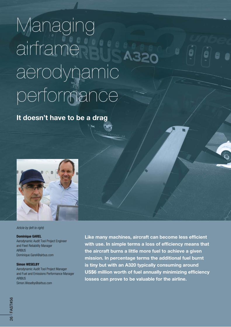
Article by (left to right)
Dominique GARELAerodynamic Audit Tool Project Engineer and Fleet Reliability [email protected]
Simon WESELBYAerodynamic Audit Tool Project Manager and Fuel and Emissions Performance [email protected]
Like many machines, aircraft can become less efficient
with use. In simple terms a loss of efficiency means that
the aircraft burns a little more fuel to achieve a given
mission. In percentage terms the additional fuel burnt
is tiny but with an A320 typically consuming around
US$6 million worth of fuel annually minimizing efficiency
losses can prove to be valuable for the airline.
Managing airframe aerodynamic performanceIt doesn’t have to be a drag
Managing airframe aerodynamic performance
27
FAS
T#56
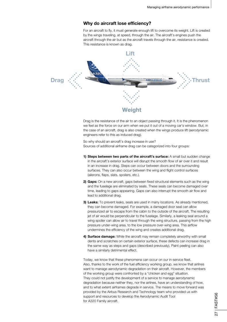
Why do aircraft lose efficiency?For an aircraft to fly, it must generate enough lift to overcome its weight. Lift is created by the wings traveling, at speed, through the air. The aircraft’s engines push the aircraft through the air but as the aircraft travels through the air, resistance is created. This resistance is known as drag.
Drag is the resistance of the air to an object passing through it. It is the phenomenon we feel as the force on our arm when we put it out of a moving car’s window. But, in the case of an aircraft, drag is also created when the wings produce lift (aerodynamic engineers refer to this as induced drag).
So why should an aircraft’s drag increase in use? Sources of additional airframe drag can be categorized into four groups:
1) Steps between two parts of the aircraft’s surface: A small but sudden change in the aircraft’s exterior surface will disrupt the smooth flow of air over it and result in an increase in drag. Steps can occur between doors and the surrounding surfaces. They can also occur between the wing and flight control surfaces (ailerons, flaps, slats, spoilers, etc.).
2) Gaps: On a new aircraft, gaps between fixed structural elements such as the wing and the fuselage are eliminated by seals. These seals can become damaged over time, leading to gaps appearing. Gaps can also interrupt the smooth air flow and lead to additional drag.
3) Leaks: To prevent leaks, seals are used in many locations. As already mentioned, they can become damaged. For example, a damaged door seal can allow pressurized air to escape from the cabin to the outside of the aircraft. The resulting jet of air would be perpendicular to the fuselage. Similarly, a leaking seal around a wing spoiler can allow air to travel through the wing structure, passing from the high pressure under-wing area, to the low pressure over-wing area. This airflow undermines the efficiency of the wing and creates additional drag.
4) Surface damage: While the aircraft may remain completely airworthy with small dents and scratches on certain exterior surface, these defects can increase drag in the same way as steps and gaps (described previously). Paint peeling can also have a similarly detrimental effect.
Lift
Weight
ThrustDrag
Today, we know that these phenomena can occur on our in-service fleet. Also, thanks to the work of the fuel efficiency working group, we know that airlines want to manage aerodynamic degradation on their aircraft. However, the members of the working group were confronted by a “chicken and egg” situation. They could not justify the development of a service to manage aerodynamic degradation because neither they, nor the airlines, have an understanding of how, and to what extent airframes degrade in service. The means to move forward was provided by the Airbus Research and Technology team who provided us with support and resources to develop the Aerodynamic Audit Tool for A320 Family aircraft.

28
FAS
T#56
Managing airframe aerodynamic performance
Airbus’ Aerodynamic Audit Tool for A320 Family aircraft While developing the tool, Airbus wanted to minimize the inspection costs: particular attention was paid to defining “simple” inspections that do not require specific tooling or disassembly. However, activation of some aircraft systems cannot be avoided, hydraulic pressurization, for example, is required to stabilize flight control surfaces and allow access to spoiler and slat seals. The order in which the inspections are proposed has also been considered, again with the objective of minimizing the time required.
iPad® application hosts the list of inspections for a complete aerodynamic audit via intuitive and ergonomic screens.

29
FAS
T#56
Managing airframe aerodynamic performance
Airlines wishing to explore the aerodynamic condition of their A320 Family aircraft using the Aerodynamic Audit Tool are invited to contact Airbus. The tool will be available on a free-of-charge basis during the investigation period. Airbus plans to release the tool during the third quarter of 2015 – the investigation will last six months.
Following the completion of the investigation, Airbus will be in a position to decide if indeed the tool can be made commercially available. Commercialisation would allow the tool’s applicability to be extended to other aircraft programmes and, potentially, allow new functions to further optimize the audit process to be implemented and versions of the tool for other computing devices.
Additional fuel consumption associated with each defect computed and made available to nominated airline personnel.
Screen mock-up shown.
Zone
Leftwing
Right wingFwd FusAft Fus
Slat 1 average mis-rig...
Spoiler 1 average mis-rig...
Flap seal - inboardFlap seal - outboard
Flap Seal - Outboard - wingto surface
...Spoiler 1 seal - cordwise
...Flap Track Fairing 4 - Fixed
to Movable steps...
Upper wing paint (fwd-inbd) .........
None-
0.2 cm-
8 cm0 cm
0 cm
-15 cm
-0.5 cm
-X:80 cm Y:60 cm P.50 %
None-
T P-T
None
None
-None
-
T
-P
0-0-50
0
-6-
1
-4
InspectionRecorded findings
Finding Addinfo.
Fuel Penalty(KGs per FH)
---
---
fwd-inbd = Forward inboard Fwd fus = forward fusilage T = text P = pictures
30
FAS
T#56
Managing airframe aerodynamic performance
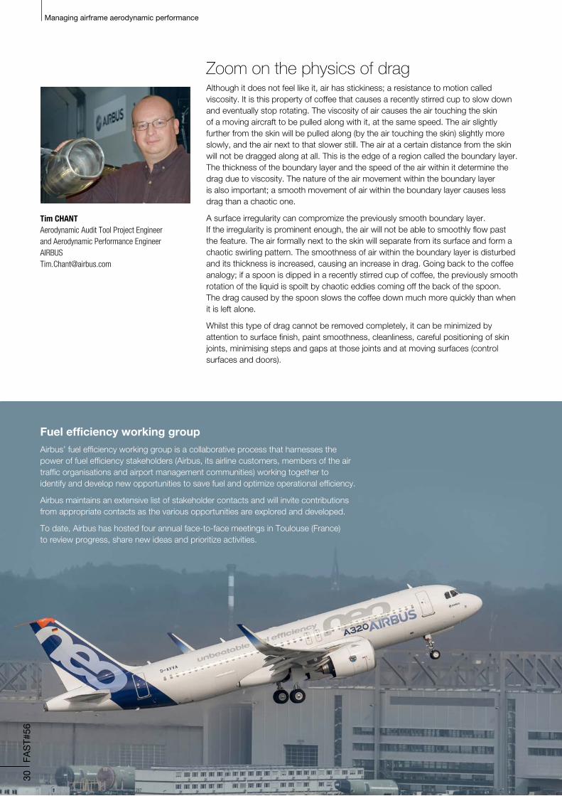
Fuel efficiency working groupAirbus’ fuel efficiency working group is a collaborative process that harnesses the power of fuel efficiency stakeholders (Airbus, its airline customers, members of the air traffic organisations and airport management communities) working together to identify and develop new opportunities to save fuel and optimize operational efficiency.
Airbus maintains an extensive list of stakeholder contacts and will invite contributions from appropriate contacts as the various opportunities are explored and developed.
To date, Airbus has hosted four annual face-to-face meetings in Toulouse (France) to review progress, share new ideas and prioritize activities.
Zoom on the physics of dragAlthough it does not feel like it, air has stickiness; a resistance to motion called viscosity. It is this property of coffee that causes a recently stirred cup to slow down and eventually stop rotating. The viscosity of air causes the air touching the skin of a moving aircraft to be pulled along with it, at the same speed. The air slightly further from the skin will be pulled along (by the air touching the skin) slightly more slowly, and the air next to that slower still. The air at a certain distance from the skin will not be dragged along at all. This is the edge of a region called the boundary layer. The thickness of the boundary layer and the speed of the air within it determine the drag due to viscosity. The nature of the air movement within the boundary layer is also important; a smooth movement of air within the boundary layer causes less drag than a chaotic one.
A surface irregularity can compromize the previously smooth boundary layer. If the irregularity is prominent enough, the air will not be able to smoothly flow past the feature. The air formally next to the skin will separate from its surface and form a chaotic swirling pattern. The smoothness of air within the boundary layer is disturbed and its thickness is increased, causing an increase in drag. Going back to the coffee analogy; if a spoon is dipped in a recently stirred cup of coffee, the previously smooth rotation of the liquid is spoilt by chaotic eddies coming off the back of the spoon. The drag caused by the spoon slows the coffee down much more quickly than when it is left alone.
Whilst this type of drag cannot be removed completely, it can be minimized by attention to surface finish, paint smoothness, cleanliness, careful positioning of skin joints, minimising steps and gaps at those joints and at moving surfaces (control surfaces and doors).
Tim CHANTAerodynamic Audit Tool Project Engineer and Aerodynamic Performance [email protected]
Zoom on engine efficiencyIn addition to the loss of efficiency due to increasing drag on the airframe, the aircraft’s engines can become less efficient with use. A contributor is the accumulation of tiny particles of dirt and other substances on the surfaces of the engine’s fan and compressor aerofoils. These aerofoils have very precise profiles that contribute significantly to the engine’s efficiency. So, particles accumulate, profiles change, efficiency reduces and fuel burn increases.
Unlike airframe drag, engine degradation is a widely recognized phenomenon in the commercial aviation industry. Typically, it is controlled through an engine washing programme that removes most of the accumulated particles and restores some of the engine’s efficiency (efficiency is not fully restored as normal engine wear also affects efficiency).
Note: Your engine maintenance provider can advise on washing programmes and cost effective engine maintenance schedules.
C O N C L U S I O N
The Aerodynamic Audit Tool Research and Technology project will allow Airbus and operators of A320 Family aircraft to have a far more complete understanding of airframe in-service performance degradation.
For success the project requires as many airlines as possible to perform audits on as many aircraft as possible - new and old, across the world. We have designed the audit process to be simple and low-cost. The audit tool and the analysis of the findings will be provided free-of-charge during the investigation period. Initial assessments suggest that, once the detected defects are corrected, net savings in excess of US$25,000 per aircraft per year might be possible.
All A320 Family operators are invited to participate in the project and may contact Airbus at any time during the investigation (scheduled to run for 6 months from third quarter 2015).
As ever, Airbus is looking for effective ways of helping its customers become more successful with its products – hoping that this project will demonstrate the added value of maintaining the aircraft’s aerodynamic condition for the benefit of the operators.
31
FAS
T#56
Managing airframe aerodynamic performance
Economic assessment – a starting pointWhile we do not yet have a clear view of the actual aerodynamic defects occurring on an A320 Family aircraft, we can evaluate the economics of the additional fuel being consumed and the cost of fixing the defect. By making some conservative assumptions about the size of the defects (step and gap sizes, length of damaged seal, etc.) we can express the cost of correcting a defect in terms of the time that defect needs to consume the same value in fuel. In some cases the figure may be as little as two weeks (i.e. in two weeks the defect has resulted in an additional fuel burn that is equivalent to the cost of finding and fixing it), the majority of defects are less than two months and for the lower impact or higher correction cost items, the figure may be of four months.

32
FAS
T#56
??
Article by (left to right)
Mohammed-Amine MCHACHTIElectrical System [email protected]
Jean-Marc THEVENOUDMarketing ManagerSaft [email protected]
Taking lithium-ion technology to new heightsLess weightand less maintenancefor batteries
Airbus has been working in collaboration with Saft, the world leader in industrial batteries, since Airbus’ origin in the 1970s. Saft currently provides batteries for all Airbus aircraft and has been selected to provide the new generation lithium-ion (Li-ion) battery technology on the A350.
Ranging from small consumer applications such as smartphones and touchpads, to large industrial applications in railways, telecommunications, electric vehicles, military aircraft and satellites, Li-ion batteries have established an outstanding track record over many years. For example, more than 1.6MWh of Saft Li-ion batteries are currently in orbit, delivering reliable on-board power for over 125 different satellites.
Batteries on A350 aircraft
There are four identical and interchangeable batteries installed in the A350 avionics bay. Along with their charging role, they also provide a ‘no break power’ (NBPT) function, meaning that the batteries are permanently connected to the aircraft’s direct current buses in order to ensure continuous power during electrical network reconfig-urations between the Auxiliary Power Unit (APU) shutdown and engine start, engine shutdown and APU start, etc.

33
FAS
T#56
Li-ion batteries
On the A350, the batteries perform several vital functions:
Emergency batteries 1 and 2
• Emergency Electricity (EMER ELEC): In case of emergency - Total Engine Flame Out (TEFO) or Loss of Main Electrical System (LMES), the batteries supply vital parts of the network during the Ram Air Turbine (RAT) deployment, last phases of landing and emergency evacuation
• Aircraft power on ground
• Power Distribution Maintenance Interface (PDMI) on battery: enabling the maintenance operator to open/close the newly introduced SSPC/RCCB technologies
Main battery 1
• Towing on battery: enabling power during the towing of the aircraft
• Auxiliary Power Unit (APU) start (+ main battery 2): to start the APU
Main battery 2
• Refuel on battery (+ main battery 1): enabling the refuelling
Advantages • Lighter By using only four Li-ion batteries on the A350, Airbus has reduced weight by more than 80kg, contributing to reduction in fuel consumption.
• On-board controls Direct control from cockpit panel.
• Real-time communications The batteries charge and health can be constantly monitored in real-time and have autonomous Built In Test Equipement.
• Less frequent maintenance checks The regular checks, periodical check and general overhaul needed with other types of batteries are now replaced with a single check every two years up to 6 years and then on a yearly basis.
As Saft Li-ion cells are hermetically
sealed and never need servicing,
maintenance operations are
essentially capacity checks every
two years.
These checks also have the added
advantage of being performed
directly on the aircraft using the
BattCARE® Ground Support
Equipment (GSE), thus saving
considerable time for the operator.

34
FAS
T#56
Li-ion batteries
35
FAS
T#56
Li-ion batteries
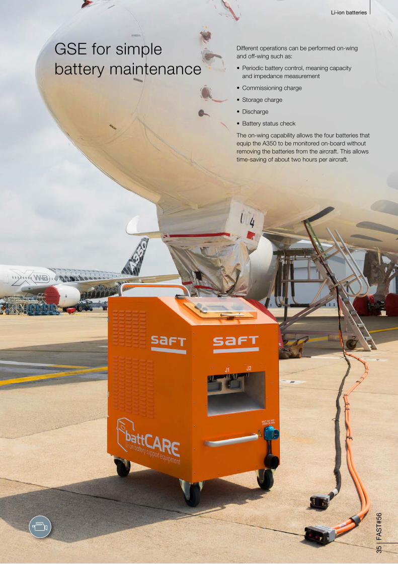
GSE for simple battery maintenance
Different operations can be performed on-wing and off-wing such as:
• Periodic battery control, meaning capacity and impedance measurement
• Commissioning charge
• Storage charge
• Discharge
• Battery status check
The on-wing capability allows the four batteries that equip the A350 to be monitored on-board without removing the batteries from the aircraft. This allows time-saving of about two hours per aircraft.
36
FAS
T#56
Li-ion batteries
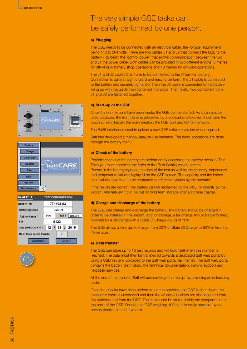
The very simple GSE tasks can be safely performed by one person.a) Plugging
The GSE needs to be connected with an electrical cable, the voltage requirement being 110 to 264 volts. There are two cables J1 and J2 that connect the GSE to the battery - J2 being the ‘control power’ that allows communication between the two and J1 the power cable. Both cables can be provided in two different lengths: 3 metres for off-wing or battery shop operations and 18 metres for on-wing operations.
The J1 and J2 cables then have to be connected to the lithium-ion battery. Connection is quite straightforward and easy to perform. The J1 cable is connected to the battery and securely tightened. Then the J2 cable is connected to the battery lining up with the guide then tightened into place. Then finally, two contacters from J1 and J2 are fastened together.
b) Start-up of the GSE
Once the connections have been made, the GSE can be started. As it can also be used outdoors, the front panel is protected by a polycarbonate cover. It contains the touch screen display, the main breaker, the USB port and RJ45 interfaces.
The RJ45 interface is used to upload a new GSE software version when required.
Saft has developed a friendly, easy-to-use interface. The basic operations are done through the battery menu.
c) Check of the battery
Periodic checks of the battery are performed by accessing the battery menu -> Test. Then you must complete the fields of the ‘Test Configuration’ screen. Record in the battery logbook the date of the test as well as the capacity, impedance and temperature values displayed on the GSE screen. The capacity and the imped-ance values have then to be compared to reference values by the operator.
If the results are correct, the battery can be recharged by the GSE, or directly by the aircraft. Alternatively it can be put on long term storage after a storage charge.
d) Charge and discharge of the battery
The GSE can charge and discharge the battery. The battery should be charged in order to be installed in the aircraft, and for storage, a full charge should be performed; followed by a discharge with a State Of Charge (SOC) of 70%.
The GSE allows a very quick charge, from 20% of State Of Charge to 90% in less than 45 minutes.
e) Data transfer
The GSE can store up to 16 test records and will lock itself when this number is reached. The data must then be transferred towards a dedicated Saft web portal by using a USB key and uploaded to the Saft web portal via internet. The Saft web portal contains the battery test history, the technical documentation, training support and helpdesk services.
At the end of the transfer, Saft will acknowledge the receipt by providing an unlock key code.
Once the checks have been performed on the batteries, the GSE is shut down, the connector cable is unscrewed and then the J2 and J1 cables are disconnected from the batteries and from the GSE. The cables can be stored inside the compartment at the back of the GSE. Despite the GSE weighing 100 kg, it is easily movable by one person thanks to its four wheels.
37
FAS
T#56
Li-ion batteries
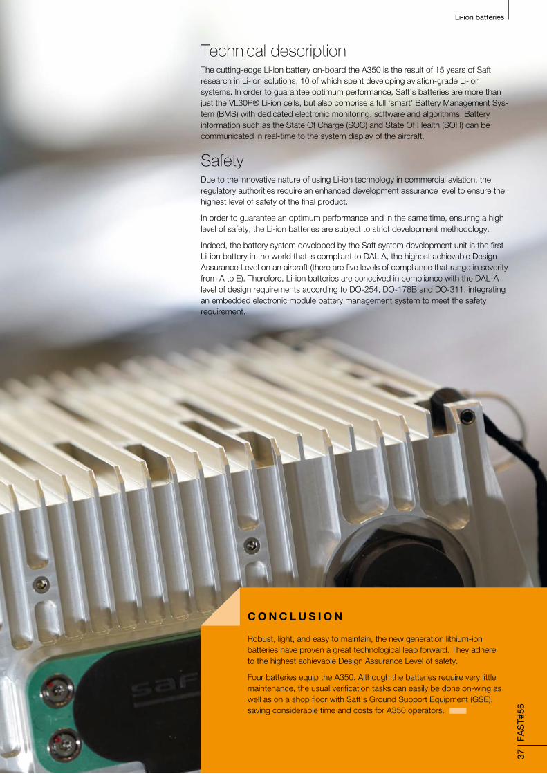
Technical descriptionThe cutting-edge Li-ion battery on-board the A350 is the result of 15 years of Saft research in Li-ion solutions, 10 of which spent developing aviation-grade Li-ion systems. In order to guarantee optimum performance, Saft’s batteries are more than just the VL30P® Li-ion cells, but also comprise a full ‘smart’ Battery Management Sys-tem (BMS) with dedicated electronic monitoring, software and algorithms. Battery information such as the State Of Charge (SOC) and State Of Health (SOH) can be communicated in real-time to the system display of the aircraft.
SafetyDue to the innovative nature of using Li-ion technology in commercial aviation, the regulatory authorities require an enhanced development assurance level to ensure the highest level of safety of the final product.
In order to guarantee an optimum performance and in the same time, ensuring a high level of safety, the Li-ion batteries are subject to strict development methodology.
Indeed, the battery system developed by the Saft system development unit is the first Li-ion battery in the world that is compliant to DAL A, the highest achievable Design Assurance Level on an aircraft (there are five levels of compliance that range in severity from A to E). Therefore, Li-ion batteries are conceived in compliance with the DAL-A level of design requirements according to DO-254, DO-178B and DO-311, integrating an embedded electronic module battery management system to meet the safety requirement.
C O N C L U S I O N
Robust, light, and easy to maintain, the new generation lithium-ion batteries have proven a great technological leap forward. They adhere to the highest achievable Design Assurance Level of safety.
Four batteries equip the A350. Although the batteries require very little maintenance, the usual verification tasks can easily be done on-wing as well as on a shop floor with Saft’s Ground Support Equipment (GSE), saving considerable time and costs for A350 operators.
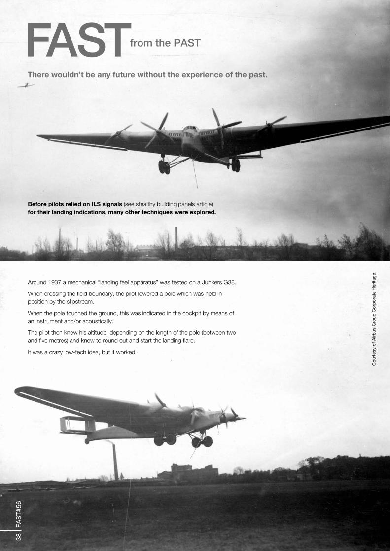
There wouldn’t be any future without the experience of the past.
FASTfrom the PAST
38
FAS
T#56
Before pilots relied on ILS signals (see stealthy building panels article) for their landing indications, many other techniques were explored.
Around 1937 a mechanical “landing feel apparatus” was tested on a Junkers G38.
When crossing the field boundary, the pilot lowered a pole which was held in position by the slipstream.
When the pole touched the ground, this was indicated in the cockpit by means of an instrument and/or acoustically.
The pilot then knew his altitude, depending on the length of the pole (between two and five metres) and knew to round out and start the landing flare.
It was a crazy low-tech idea, but it worked!
Cou
rtes
y of
Airb
us G
roup
Cor
por
ate
Her
itage

We’ve got it covered Around the clock, around the world,
Airbus has more than 240 field representatives
based in over 110 cities
WORLDWIDE
Tel: +33 (0)5 6719 1980
Fax: +33 (0)5 6193 1818
USA/CANADA
Tel: +1 703 834 3484
Fax: +1 703 834 3464
CHINA
Tel: +86 10 8048 6161 Ext. 5020
Fax: +86 10 8048 6162
FIELD SERVICE SUPPORT
ADMINISTRATION
Tel: +33 (0)5 6719 0413
Fax: +33 (0)5 6193 4964
TECHNICAL, MATERIAL & LOGISTICS
Airbus Technical AOG Centre (AIRTAC)
Tel: +33 (0)5 6193 3400
Fax:+33 (0)5 6193 3500
Spares AOG/Work Stoppage
• Outside the Americas:
Tel: +49 (0)40 5076 4001
Fax: +49 (0)40 5076 4011
• In the Americas:
Tel: +1 70 3729 9000
Fax: +1 70 3729 4373
Spares In-Flight orders outside the Americas:
Tel: +49 (0)40 5076 4002
Fax: +49 (0)40 5076 4012
Spares related HMV issues outside the Americas:
Tel: +49 (0)40 5076 4003
Fax: +49 (0)40 5076 4013
Spares RTN/USR orders in the Americas:
Please contact your dedicated customer spares
account representative [email protected]
TRAINING CENTRES
Airbus Training Centre
Toulouse, France
Tel: +33 (0)5 6193 3333
Fax: +33 (0)5 6193 2094
Airbus Maintenance
Training Centre
Hamburg, Germany
Tel: +49 (0)40 7438 8288
Fax: +49 (0)40 7438 8588
Airbus Training Centre Americas
Miami, Florida - U.S.A.
Tel: +1 305 871 3656
Fax: +1 305 871 4649
39
FAS
T#56

How can I fly more passengers to the most popular airports at peak times?
airbus.com© AIRBUS, 2015. All rights reserved. Airbus, its logo and the product names are registered trademarks.
Fly the A380. The world’s most spacious commercial aircraft. Capture more high-yield traffic on the busiest routes and offer the highest passenger appeal with 18+ inch seats in economy.Airbus is the answer.
12206_AIR_QA_TowerBridge_Fast_297x210_1.0.indd 1 23/06/2015 14:31