flight results of the hst sm4 relative navigation sensor ... · flight results from the hst sm4...
TRANSCRIPT

AAS 10-086
Flight Results of the HST SM4
Relative Navigation Sensor System
Bo Naasz, John Van Eepoel, Steve Queen, C. Michael Southward, Joel Hannah
NASA Goddard Space Flight Center (GSFC)
33rd
ANNUAL AAS GUIDANCE AND CONTROL CONFERENCE
February 6 - February 10, 2010 Sponsored by
Breckenridge, Colorado Rocky Mountain Section
AAS Publications Office, P.O. Box 28130 - San Diego, California 92198
https://ntrs.nasa.gov/search.jsp?R=20100014897 2020-06-03T16:34:15+00:00Z

AAS 08-280
FLIGHT RESULTS FROM THE HST SM4 RELATIVE NAVIGATIONSENSOR SYSTEM
Bo J. Naasz∗, John Van Eepoel†, Steven Z. Queen‡, and C. MichaelSouthward II§, Joel Hannah¶
On May 11, 2009, Space Shuttle Atlantis roared off of Launch Pad 39A enroute tothe Hubble Space Telescope (HST) to undertake its final servicing of HST, Servic-ing Mission 4. Onboard Atlantis was a small payload called the Relative NavigationSensor experiment, which included three cameras of varying focal ranges, avion-ics to record images and estimate, in real time, the relative position and attitude(aka ”pose”) of the telescope during rendezvous and deploy. The avionics package,known as SpaceCube and developed at the Goddard Space Flight Center, performedimage processing using field programmable gate arrays to accelerate this process,and in addition executed two different pose algorithms in parallel, the Goddard Nat-ural Feature Image Recognition and the ULTOR Passive Pose and Position Engine(P3E) algorithms.
INTRODUCTIONIn May of 2009, the National Aeronautics and Space Administration (NASA) Goddard Space
Flight Center (GSFC) completed a successful on-orbit demonstration of its Relative NavigationSensor (RNS) system. Flown in the cargo bay of Space Shuttle Atlantis during the highly success-ful Hubble Space Telescope (HST) Servicing Mission 4 (SM4), RNS captured and stored severalhours of imagery of the telescope, as well as raw Global Positioning System (GPS) data, during theRendezvous Proximity Operations and Docking (RPOD) and Deploy phases of the mission. Thesystem also processed images of Hubble in real-time, estimating the position and orientation, or“pose” of the telescope relative to RNS’s Shuttle-mounted cameras.
The RNS experiment on SM4 was originally conceived of in the course of developing a prelimi-nary mission concept and spacecraft design for the Hubble Space Telescope Robotic Servicing andDe-orbit Mission (HRSDM). Intended to successfully rendezvous and dock with an uncontrolledHST, the servicing vehicle required an autonomous means for real-time estimation of the relativeposition and attitude of HST. We refer to this relative state measurement, made directly from sensordata without consideration of the system dynamics, as the “pose” measurement.
The RNS experiment leveraged hardware procured prior to the cancellation of HRSDM to as-semble a relative navigation sensor payload, RNS, to be installed in the Space Shuttle payload bayduring SM4. Hosted on the Multi-use Logistic Equipment Carrier (MULE), RNS made real-timepose measurements during approach to and departure from HST during SM4. The objectives ofRNS were: 1) to record images of HST, especially of a new Soft Capture Mechanism (SCM) being∗Aerospace Engineer, NASA GSFC, Code 595, Greenbelt, MD 20771†Aerospace Engineer, NASA GSFC, Code 591, Greenbelt, MD 20771‡Aerospace Engineer, NASA GSFC, Code 591, Greenbelt, MD 20771§Aerospace Engineer, Emergent Space Technologies, Inc., Greenbelt, MD 20770¶Electrical/Software Engineering Manager, Advanced Optical Systems, Inc., Huntsville, AL 35806
1
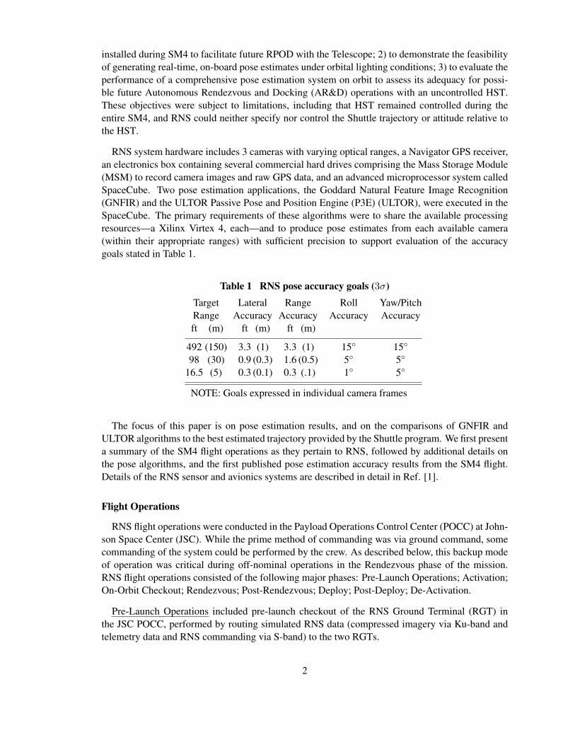
installed during SM4 to facilitate future RPOD with the Telescope; 2) to demonstrate the feasibilityof generating real-time, on-board pose estimates under orbital lighting conditions; 3) to evaluate theperformance of a comprehensive pose estimation system on orbit to assess its adequacy for possi-ble future Autonomous Rendezvous and Docking (AR&D) operations with an uncontrolled HST.These objectives were subject to limitations, including that HST remained controlled during theentire SM4, and RNS could neither specify nor control the Shuttle trajectory or attitude relative tothe HST.
RNS system hardware includes 3 cameras with varying optical ranges, a Navigator GPS receiver,an electronics box containing several commercial hard drives comprising the Mass Storage Module(MSM) to record camera images and raw GPS data, and an advanced microprocessor system calledSpaceCube. Two pose estimation applications, the Goddard Natural Feature Image Recognition(GNFIR) and the ULTOR Passive Pose and Position Engine (P3E) (ULTOR), were executed in theSpaceCube. The primary requirements of these algorithms were to share the available processingresources—a Xilinx Virtex 4, each—and to produce pose estimates from each available camera(within their appropriate ranges) with sufficient precision to support evaluation of the accuracygoals stated in Table 1.
Table 1 RNS pose accuracy goals (3σ)Target Lateral Range Roll Yaw/PitchRange Accuracy Accuracy Accuracy Accuracyft (m) ft (m) ft (m)
492 (150) 3.3 (1) 3.3 (1) 15◦ 15◦
98 (30) 0.9 (0.3) 1.6 (0.5) 5◦ 5◦
16.5 (5) 0.3 (0.1) 0.3 (.1) 1◦ 5◦
NOTE: Goals expressed in individual camera frames
The focus of this paper is on pose estimation results, and on the comparisons of GNFIR andULTOR algorithms to the best estimated trajectory provided by the Shuttle program. We first presenta summary of the SM4 flight operations as they pertain to RNS, followed by additional details onthe pose algorithms, and the first published pose estimation accuracy results from the SM4 flight.Details of the RNS sensor and avionics systems are described in detail in Ref. [1].
Flight Operations
RNS flight operations were conducted in the Payload Operations Control Center (POCC) at John-son Space Center (JSC). While the prime method of commanding was via ground command, somecommanding of the system could be performed by the crew. As described below, this backup modeof operation was critical during off-nominal operations in the Rendezvous phase of the mission.RNS flight operations consisted of the following major phases: Pre-Launch Operations; Activation;On-Orbit Checkout; Rendezvous; Post-Rendezvous; Deploy; Post-Deploy; De-Activation.
Pre-Launch Operations included pre-launch checkout of the RNS Ground Terminal (RGT) inthe JSC POCC, performed by routing simulated RNS data (compressed imagery via Ku-band andtelemetry data and RNS commanding via S-band) to the two RGTs.
2

15:00 16:00 17:00 18:00
Berth HST Grapple HST
Shuttle to Inertial Hold Shuttle Yaw
Ground GNFIR Track (RNS2) HST Visible in RNS2 FOV
Rend. Radar to Comm Flt GNFIR Track (RNS1)
Ground GNFIR Track (RNS1)HST Visible in RNS1 FOV
MSM Recording (GPS/Cam) Command String Switchover
VIM Recording RNS Sensors Powered
Orbit Day
GMT (starting on 05/13/2009)
Figure 1 Rendezvous events timeline
Activation of the RNS Telemetry Module (TM) was perfomed at Mission Elapsed Time (MET)0/02:33∗ (11 May 2009, 20:35 GMT). The TM remained powered for the remainder of the RNSoperations, and provided health and safety telemetry during periods when SpaceCube–the primarysource of RNS telemetry–was de-activated.
On-Orbit Checkout commenced at MET 0/14:17 (12 May 2009, 08:19 GMT) via ground com-mand from the RGT. Checkout included the first power-up of the RNS sensors† and avionics on orbitfor verification. Proper operation of the system was verified when imagery of Earth, first recorded,and then live, were transmitted from the RNS system to the RGT via the Shuttle’s Ku-band link.Power switching and sensor data recording via Atlantis Crew command were also verified at thispoint.
Rendezvous Operations commenced with power-up of the RNS operational heaters at MET1/19:40 (13 May 2009, 13:42 GMT) in preparation for rendezvous recording and pose estimationthroughout the RPOD phase. Figure 1 shows the sequence of events during Rendezvous.
RNS imaging operations during the Rendezvous phase commenced just after the Shuttle MC4burn – the final mid-course correction which targets the “R-bar” (HST nadir axis, as shown in Fig-ure 2). At this point in the RPOD phase, the Atlantis crew had already commanded the Shuttle to a“target track” attitude, with the HST-target at approximately the 1000 ft range and positioned abovethe Shuttle payload bay as shown in Figure 2 (the original figure, and more thorough description ofthe RPOD phase are available in Ref. [2]). HST was operational, in the “rendezvous” attitude asshown in Figure 2, with Solar “Beta” angle of approximately −10o.
At this point in the rendezvous sequence RNS heaters were bringing the system up to its opera-tional temperature, the vehicles were passing through orbit night, and the ground team was debug-ging an issue with the Shuttle-HST S-band link, through which they needed to command HST to itsfinal grapple configuration. After several other attempts failed, the ground team decided to switchover commanding of the Shuttle payloads to the backup hardware. While this did not resolve the
∗MET, or Mission Elapsed Time format is D/HH:MM :SS. MET 0/00:00:00 corresponds to HST SM4 liftoffat May 11, 2009 18:01:56 GMT. Detailed information on HST commanding during the servicing mission are availablein the As Executed versions of the “Servicing Mission 4 Command Plan” and “HST Servicing Mission 4 IntegratedTimeline (SMIT)”.†RNS sensors include 3 cameras, and the Navigator GPS receiver, always powered on and off simultaneously.
3
t--...... " ,,' " , " ::::::::::::: :;;;ii=:===: ~ , , . , , . , , . ,
"'"'''''' '' ,, ' ,, ' ,,',, ' ,, " , """- ",, "",, " ,,""'" "",, ' '' ' " ,I ,
"'" ' ''''''' ,, ' ,, ' ,,'"'''''' """ "' ''''' . '' . "" ' ''''''''' "",, ''' ' """", . ," • • " . " • • ,""',. "",,·,, · ,"' t , . ""', . ,""" """', . ,
"'" ' ''''''' . " " , ,,,,,,,,,,, """' '' '''''' 1 """, ",,"'''' "","' "
""".,,"" .,,""""""" """.,,""'" ", I """""", "",, ' '' ' """.,,"" .,,""""""" """.,,"""" """""""'" ", I ,, ' '' '

Figure 2 Shuttle R-Bar approach to HST and planned HST “rendezvous” and “grap-ple” attitudes (note that HST remained in the “rendezvous” attitude throughout thesequence, never maneuvering to the “grapple” attitude)
issue, it did remove any possibility of RNS ground commanding for the remainder of the sequence(RNS ground commanding was limited to the primary communication hardware).‡
A second consequence of the Shuttle-HST link issue was that HST ground controllers in the SpaceTelescope Operations Control Center (STOCC) opted to forgo the HST roll maneuver to the “grap-ple” attitude. This misalignment would be removed later in the sequence by a crew-commandedShuttle yaw maneuver of about 45◦ about the Payload Bay (Shuttle zenith) axis, performed at aninter-vehicle range of approximately 150 ft at MET 1/22:51 (13 May 2009, 16:53 GMT). Thischange to the relative approach attitude resulted in RNS being mis-configured for the initial pose ac-quisition. Ground commanding at this point could have adjusted the RNS pose algorithm acquisitionmodes. Unfortunately RNS commanding was not possible at this point due to the aforementionedcommand string switch over.
Upon notification that command switch over would occur, the RNS ground team powered up thesystem and executed those commands which could not be performed by the Crew (including initia-tion of compressed image recording on the SpaceCube Video Interface Module (VIM)§). Recordingof uncompressed imagery and GPS recording would be initiated at the originally planned time viaCrew command which was still possible after the command string switchover.
The remainder of the RPOD phase was nominal. The HST remained in an inertial hold through-out the sequence as the Atlantis Crew completed the “R-Bar” approach. The crew performed theyaw maneuver at approximately a range of 150 ft to align for grapple, transitioned the Shuttle’sattitude control system to inertial hold at an inter-vehicle range of approximately 130 ft to matchrates with HST, and performed the final grapple and berth of the telescope using the Shuttle Remote‡The issue was later resolved by reconfiguration of the link parameters on the HST side and RNS commanding was
restored.§The VIM recording script commenced almost an hour earlier than planned. The script was to cycle through cameras
in an open loop fashion, recording compressed imagery at the times when HST was expected to be in their field of view.Because the script started early, very little of the recorded imagery shows HST. One benefit of this timing change is thatVIM-recorded imagery, intended to be a redundant backup to MSM-recorded imagery, is unique.
4
"" '"" '""
~:H(~FT) ( HST·Cenlered LVLH F rame
HST AmTUoe
G~~ASVI~O OR81TER
.H~~' (YL~)'9' =:

Manipulator System (SRMS). As with previous HST servicing missions, the grapple occurred wellafter sunset, and RNS imagery of the final 130 ft of the approach is quite dark, since the Shuttlefloodlights were the only source of illumination during orbit night.
RNS rendezvous operations ceased with a crew-commanded stop recording and deactivation ofthe system at approximately 18:30 GMT.
Figure 3 Image of Earth taken by RNS2 during RNS checkout (left), and of HSTtaken by RNS1 during rendezvous (right)
Post-Rendezvous operations consisted of Ku-band downlink of the rendezvous imagery, and com-manding to prepare the RNS system for Deploy operations. In the days between Rendezvous andDeploy operations, the RNS team downlinked compressed imagery from all 3 cameras from theMSM using MSM playback, VIM compression, and SpaceCube transmission to the Shuttle Ku-band downlink system.
Ku downloads of recorded rendezvous images occurred on Flight Days (FD) 3, 4, 5, 6, 7 and8. As a result of the downloads, approximately 81.5% of the recorded rendezvous images weredownlinked for evaluation of camera Automatic Gain Control (AGC) performance. In total, 62,480unique images were downlinked over the course of 6 nights, representing almost 6 hours of uniquecamera footage.
Evaluation of rendezvous imagery confirmed adequate performance with no updates to the cam-era AGC parameters necessary. Onboard storage space was confirmed to be adequate for deploy, thepose algorithms were commanded to Deploy Mode, and the system was ready for deploy operations.
Deploy Operations were a critical time for RNS for it was this time to meet its major requirementof imaging of the new SCM installed on the aft bulkhead of HST. To properly image the SCM,the RNS Intermediate Position (RIP) was added into the timeline as part of the nominal missionplan. Therefore, deploy operations began at MET 07/14:44 (19 May 2009, 08:46 GMT), aheadof the scheduled un-berthing of HST. Operational heaters and the SpaceCube were powered onvia commands from the RGT. The sensors and MSMs were powered on at MET 07/15:48 (09:50GMT), also via RGT command. Recording for deploy was initiated at MET 07/16:19 (10:21 GMT)via RGT command. The payload bay floodlights were turned on at MET 07/17:18 (11:20 GMT).
5

Figure 4 Image of HST Soft Capture Mechanism (SCM) taken by RNS3 duringdeploy, with SRMS at the RIP position (left) and by RNS2 after HST release (right)
Deploy operations events relevant to RNS are shown in Figure 5. The deployment sequence pro-gressed as follows: Atlantis crew grappled HST with the SRMS; the HST ground team commandedde-mating of the HST umbilical, and opening of the three HST berthing latches on the Shuttle-mounted Flight Support Structure (FSS); the Atlantis crew then used the SRMS to maneuver theTelescope through a series of waypoints (see Figure 6), including the “FSS Hover” position, the“RIP” position, which centered the HST SCM in the field of view of the RNS short range camera,and the “HST Release Position”. Once the HST ground team had opened the HST aperture door,and deployed the HST high gain antennas, the crew released the telescope at MET 7/19:02 (13:04GMT), and performed two small separation burns to safely depart the neighborhood of HST. TheRNS system continued to record during the final Shuttle-HST deployment.
10:00 11:00 12:00 13:00 14:00 15:00
Shuttle SEP2 Burn Shuttle SEP1 Burn
HST Release HST AD to OPEN
SRMS @ HST Release Pos. SRMS @ RIP
Flt GNFIR Track Ground GNFIR Track SRMS @ FSS Hover
HST Unberth Shuttle Free Drift
MSM Cam Recording MSM GPS Recording
RNS Sensors Powered Orbit Day
GMT (starting on 05/19/2009)
Figure 5 Deploy events timeline
At MET 07/19:46 (13:48 GMT), all camera hard drives were full, but the MSM continued torecord GPS data. At MET 07/21:06, all recording was stopped. The sensors and MSMs werepowered off at MET 07/21:07. The SpaceCube was left powered for the next 24 hours to performradiation mitigation testing.
6
""""""":""" 1 """
, , , .' , , , , , , , , ~ , , , , , , , , , , , , ': ' , , , , , , , , , , , ':' , , , , , , , , , , , ,
""' . ""'~""""""'~"""""" ':""" " "'" """ - " " """"",;""""""':'"""",,,,
""" .-"~""""""';""""""':""" " "'" """" . ":""""""':""""""':""" " "'"
"""""" '. """"""""""""" ':""" " "'"
, , , , , , , , , , , , , ~ , , , , , , '. ' , , , ,; , , , , , , , , , , , , ,:, , , , , , , , , , , , ,
""""""':"""""" f """""" ':""" " "'" , , , , , , , , , , , , , ~ , , , , , , , , , , , , '. ' , , , , , , , , , , , ':' , , , , , , , , , , , ,
, , , , , , , , , , , , , ~ , , , , , , , , , , , , ,; , , , , , .' , , , , , ':' , , , , , , , , , , , ,

Figure 6 Port views of Shuttle and HST : (top row) Grapple (left), FSS Hover (center),and FSS Berth (right); (bottom row) RIP (left) and HST Deploy (right)
Post-Deploy Operations for downlink of deploy imagery and extended SpaceCube operationsresumed during crew sleep after HST deploy. Ku downloads of recorded deploy images occurredduring only one planning shift split between Flight Days (FD) 9 and 10. This was due to the factthat the majority of the remaining Shuttle payload was deactivated to conserve power for extendedShuttle operations. Mission managers made this decision on Flight Day 10 as forward forecasts ofweather conditions at Kennedy Space Center (KSC) looked unfavorable for an on-time landing. Asa result of this single night of downloads, approximately 15.3% of the recorded Deploy images wereacquired.¶
In total, 16,990 unique images were downloaded of the HST deployment sequence for more thanan hour and a half of unique camera footage.
De-Activation of the RNS TM occurred earlier than originally planned, at MET 8/21:12:53 toconserve energy onboard Shuttle. This was necessary due to inclement weather at the primarylanding sight (KSC).
ALGORITHMSGNFIR
The GNFIR is the latest mutation of RAPiD3 - one of the first 3D trackers to run in real-time. Aswas the case with RAPiD and its numerous descendants, GNFIR utilizes natural features (edges)on its target and requires neither fiducials nor a cooperative target. GNFIR is built upon a RAPiD-derived edge-tracker re-parameterized using a Lie group formalism developed by Drummond andCipolla4 at the University of Cambridge. This approach assumes a monocular (single camera)system and requires an internal three-dimensional stick-model of the edge features of interest.
¶All Rendezvous and Deploy images are currently available in uncompressed format: they have been recovered fromthe MSMs during post-flight operations at GSFC.
7
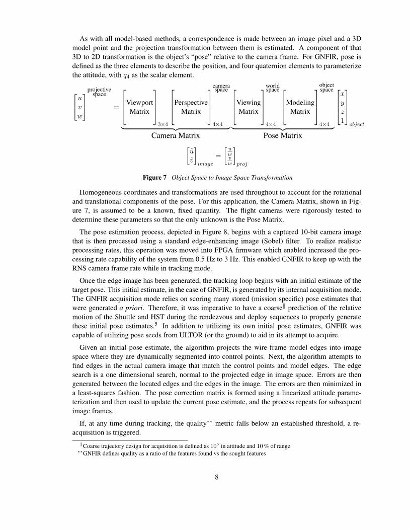
As with all model-based methods, a correspondence is made between an image pixel and a 3Dmodel point and the projection transformation between them is estimated. A component of that3D to 2D transformation is the object’s “pose” relative to the camera frame. For GNFIR, pose isdefined as the three elements to describe the position, and four quaternion elements to parameterizethe attitude, with q4 as the scalar element.
uvw
projective
space
=
ViewportMatrix
3×4
PerspectiveMatrix
cameraspace
4×4︸ ︷︷ ︸Camera Matrix
ViewingMatrix
worldspace
4×4
ModelingMatrix
objectspace
4×4︸ ︷︷ ︸Pose Matrix
xyz1
object
[uv
]image
=[
uwvw
]proj
Figure 7 Object Space to Image Space Transformation
Homogeneous coordinates and transformations are used throughout to account for the rotationaland translational components of the pose. For this application, the Camera Matrix, shown in Fig-ure 7, is assumed to be a known, fixed quantity. The flight cameras were rigorously tested todetermine these parameters so that the only unknown is the Pose Matrix.
The pose estimation process, depicted in Figure 8, begins with a captured 10-bit camera imagethat is then processed using a standard edge-enhancing image (Sobel) filter. To realize realisticprocessing rates, this operation was moved into FPGA firmware which enabled increased the pro-cessing rate capability of the system from 0.5 Hz to 3 Hz. This enabled GNFIR to keep up with theRNS camera frame rate while in tracking mode.
Once the edge image has been generated, the tracking loop begins with an initial estimate of thetarget pose. This initial estimate, in the case of GNFIR, is generated by its internal acquisition mode.The GNFIR acquisition mode relies on scoring many stored (mission specific) pose estimates thatwere generated a priori. Therefore, it was imperative to have a coarse‖ prediction of the relativemotion of the Shuttle and HST during the rendezvous and deploy sequences to properly generatethese initial pose estimates.5 In addition to utilizing its own initial pose estimates, GNFIR wascapable of utilizing pose seeds from ULTOR (or the ground) to aid in its attempt to acquire.
Given an initial pose estimate, the algorithm projects the wire-frame model edges into imagespace where they are dynamically segmented into control points. Next, the algorithm attempts tofind edges in the actual camera image that match the control points and model edges. The edgesearch is a one dimensional search, normal to the projected edge in image space. Errors are thengenerated between the located edges and the edges in the image. The errors are then minimized ina least-squares fashion. The pose correction matrix is formed using a linearized attitude parame-terization and then used to update the current pose estimate, and the process repeats for subsequentimage frames.
If, at any time during tracking, the quality∗∗ metric falls below an established threshold, a re-acquisition is triggered.‖Coarse trajectory design for acquisition is defined as 10◦ in attitude and 10 % of range∗∗GNFIR defines quality as a ratio of the features found vs the sought features
8
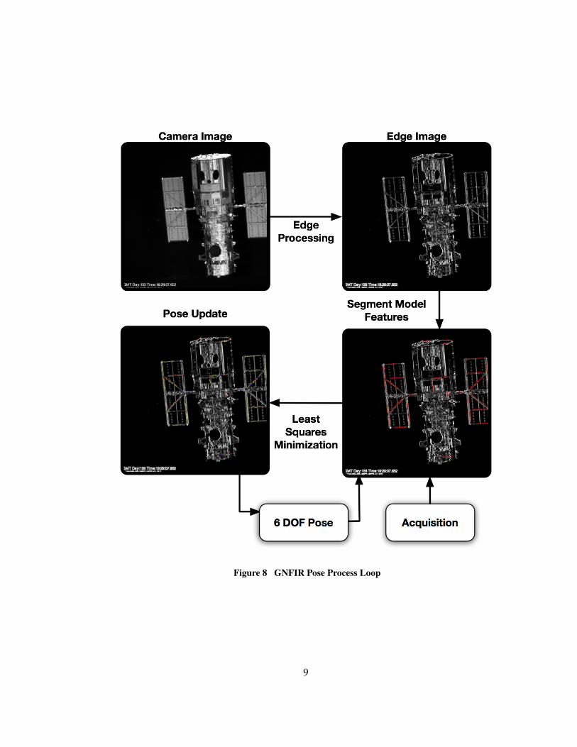
Figure 8 GNFIR Pose Process Loop
9

ULTOR R©
Advanced Optical Systems (AOS) designed the ULTOR P3E (ULTOR)6 to provide 6DOF stateestimation of objects. ULTOR exists as VHDL firmware and is designed to be reconfigurable andportable. During RNS, ULTOR processed imagery from the RNS cameras to produce real-timeresults at full camera frame rates.
Simulated imagery of HST was developed to provide training data for ULTOR of specific featureson HST in the camera field of view. The training data is processed to develop filters of the object tobe measured. The ULTOR process is based on a spatial frequency analysis of a correlation betweenthe filter and the actual object as viewed by the RNS camera. As shown in Figure 9, the relativepositions of these features based on the HST mechanical model are used to evaluate the positionand attitude of HST. An N-point perspective algorithm evaluates the spatial relationship of theestimated position features against the measured position to produce Six Degree of Freedom (6DOF)information of the object.
ULTOR acquires targets based on a search of the filter database to find the closest position andattitude. Once acquired, ULTOR transitions into tracking mode and processes through the filterdatabase basd on the motion of the object. The filter database was designed to support the spec-ified dispersion of trajectory angles based on the relative motion of the Shuttle and HST duringrendezvous and deploy.
Figure 9 Feature based ULTOR ! (ULTOR !)P3E overview
TESTINGAlluded to in the previous algorithm section, the pose algorithms place importance on synthetic
image generation. Test imagery is critical to have as an input for flight code development and veri-fication, and to predict lighting of the target for proper model-feature selection. The pose algorithmperformance is tightly coupled to the model features that are visible on the target, and therefore asystem was developed to predict the on-orbit lighting conditions for the SM4 rendezvous and deploytrajectories.
This system encompasses a tool to model and animate 3D geometry, Geomod, a physical illu-mination and rendering system, Phillum. Phillum is a stochastic path tracer that uses Monte Carloimportance sampling to follow a large number of incoming light rays from a detector grid, through
10

Figure 10 Geomod showing Phillum working on a SM4 Rendezvous Image
lenses and into a 3D geometry scene. It then traces the paths of the lights through the scene todetermine the exposure at the detector. It uses radiometric light transport, geometric optics and sta-tistically unbiased Monte Carlo integration. A screenshot of the application is shown in Figure 10.
For RNS, there is also an Automatic Gain Control (AGC) algorithm that determines the cameragain and integration interval, controlling the exposure of the next image by evaluating the infor-mation content of the current image. This creates a complex system that, without proper groundtesting, could easily result in over/under-exposed images. The RNS team had the freedom to chooseparameters for the AGC algorithm, but these could not be changed once the rendezvous or deploysequence had started. Therefore, it was imperative to determine these settings a priori and the onlyway to achieve this was through simulation of the high dynamic range imagery with Phillum. Asa testament to the accuracy of Phillum and the simulated SM4 trajectory, a comparison between aflight image and a Phillum generated image is provided in Figure 11.
Figure 11 Comparison between Phillum synthetic image (left) and a Flight image from Rendezvous
11

POSE ESTIMATION FLIGHT RESULTSThis section presents a summary of on-orbit results of the pose algorithms, comparisons to a truth
solution, and details the data analysis of the various pose solutions. The RNS hardware performedadmirably during the HST SM4 mission by recording much of the rendezvous and deploy imagery ofHST and returning it safely to the ground. During the rendezvous operations the GNFIR algorithmwas able to track HST through the RNS1 camera from a range of 97 m (318 ft) to a range of 45 m(148 ft) with a peak quality of 99.2 % and maintained a continuous track for 20 minutes and 27seconds. This success on rendezvous was mirrored in the deploy sequence of the telescope asGNFIR was able to track HST in the RNS3 camera at the hover position for 3 minutes and 48seconds, and then at the RIP position for 11 minutes and 43 seconds with a peak quality of 87.1 %.
Recall from the Rendezvous Operations section, that the RNS team was unable to issue a com-mand to the RNS system to change to a different operating mode that would have enabled betteracquisition for the pose algorithms. In the case of ULTOR, this was critical as they were unable totrack HST on-orbit. The appearance of HST in the RNS1 camera was at the edge of ULTOR’s train-ing data. ULTOR was able to produce several pose estimates with good confidence, but not enoughto transition into tracking. ULTOR did pass an initial pose seed to GNFIR that enabled it to tran-sition to tracking mode though. However, using the flight imagery, ULTOR was able to generate apost-processed ground solution by placing the algorithm in the correct operating mode. Doing thisresulted in tracking HST for 13 minutes and 33 seconds.
The performance of the pose algorithms once the rendezvous took HST out of the field of view ofRNS1 and into RNS2 was, unfortunately, not as successful. During rendezvous, GNFIR was onlyable to track for brief moments. The quality of the pose acquisition was enough to put the algorithminto tracking mode, but the acquisition time proved to be too long at 12 to 15 seconds to maintaintracking of HST as the relative range closed too quickly. Figure 12 shows the expected on-orbitlighting of HST on the left compared to the actual, on the right.
Figure 12 RNS2 with Phillum synthetic imagery (left), and Flight image (right) on Rendezvous
The combination of the variance in on-orbit lighting, the change in approach trajectory describedin the Rendezvous Operations section, and the speed of the approach all combined to cause GNFIRto not acquire on-orbit. When the flight imagery was re-processed on the ground, the GNFIR
12

algorithm was able to acquire and track HST in RNS2 for 1 minute and 43 seconds with a peakquality of 67.8 %. To achieve this the GNFIR acquisition was modified to acquire the differenttrajectory followed on rendezvous, as well as some minor model simplifications. This underscoresthe fact that much of the RNS2 imagery was quite dark during rendezvous.
Finally, for RNS3, neither GNFIR nor ULTOR tracked HST during rendezvous when it wasmoved from the grapple position to the hover position above the FSS. This was due to a varianceof 0.55 m and 3.6◦ in the expected motion of HST from the grapple position to the hover position.The features presented to the pose algorithms were similar to those expected, as shown in Figure 13.However, the differences in orientation and range were outside the expected search range and thiswas enough to cause GNFIR to not acquire HST during rendezvous. However, on deploy, GNFIRperformed quite well by tracking HST at the FSS hover position and the RIP position for a totaltime of 15 minutes and 31 seconds with a peak quality of 87.1 %.
Figure 13 RNS3 with Phillum synthetic imagery (left), and Flight image (right) on Rendezvous
In light of these issues on-orbit, the RNS experiment met all of its objectives by: 1) imaging thenewly installed SCM shown in Fig 4, 2) generating 32 minutes and 10 seconds of real-time poseestimates, 3) evaluating the performance of the pose estimation system (this paper).
Flight Data Comparison
The initial undulation of success is now tempered with comparisons of the pose flight data to inde-pendent data sources, namely the Shuttle program’s best estimated trajectory. The Shuttle program’sRelative Best Estimate Trajectory (RELBET), was produced by JSC by filtering several differentdata sources such as onboard state estimates, rendezvous radar, COAS, IMU, and star tracker mea-surements, and taking into account timeline events such as maneuvers and corrections. RELBET’s3σ accuracies at 300 m are 2 m radial, 25 m in-track, and 2 m cross-track which is further discussedin the Interface Control Document (ICD) in Ref. 7. Shuttle attitude data was taken directly frominstrument measurements, with an accuracy of 0.2◦ when Inertial Measurement Unit (IMU) data isavailable, and 0.75◦ otherwise, as given in the PATH ICD in Ref. 8. HST attitude was provided bythe HST operations team, and the published accuracy of their solution is 1 arcsec during rendezvous.During the deploy sequence, the joint angles of SRMS are used to reconstruct the relative position
13

of HST with respect to Shuttle, and eventually the RNS cameras. Accuracy of the joint encoderswas not available at the time of publication.
The positions and attitudes of HST and the Shuttle are used to create a pose solution in the cameraframe. This pose solution is then compared to the on-orbit and ground processed pose solutions forGNFIR and ULTOR. We will see discrepancies between the pose generated from Shuttle and HSTposition/attitude information, and the pose solutions from the RNS algorithms. To resolve thisdiscrepancy, the RNS flight imagery was used to justify the pose solution from the RNS algorithmsas the correct solution. As a result, the position data of the GNFIR post-processed solution will becompared to the GNFIR flight solution and the ULTOR post-processed solution. The attitude dataof the Shuttle and HST does provide a valid truth solution, and will be used in comparing to thepose solutions.
The comparison data is presented in the RNS camera frame. The camera frame is defined with+X (Cn1) to the right and +Y (Cn2) up in the image plane, where n = 1, 2, 3 for RNS1, RNS2, andRNS3, respectively. +Z (Cn3) completes the right handed triad by being into the camera boresight,thus making the −Z axis correspond roughly to range to the target. The origin is placed at thetheoretical center of the camera lens to correspond to a pin-hole camera model.
Figure 14(a) shows the different data sets of GNFIR(flight data and post-processed data), ULTORpost-processed data, and RELBET flight data. All pose solutions show the same trend for the ren-dezvous trajectory, however the RELBET solution shows a bias in all axes, most pronounced in theZ axis of the camera. Figures 15(a) and 15(b) detail the RELBET solution compared to the GNFIRflight solution. An ULTOR comparison is not possible as ULTOR did not track HST in flight, butdid track HST when post-processing the flight imagery with the appropriate filters. The comparisonplot and the RMS differences in Table 2 show a 20 m difference when compared to RELBET. How-ever, when the pose solutions are cross-compared (GNFIR vs ULTOR), the position differencesdrop dramatically to less than 0.5 m for RNS1 (see Table 1). In Figure 15(b), the comparison ofattitude data does not exhibit the same issues as position data. In this case, the attitude differencesare 2.0◦ per axis, for a magnitude of 2.65◦ for GNFIR. This on-orbit difference is much better thanthe desired error of 15◦ stated in Table 1. The bottom plot of Figure 15(b) shows the principal anglethat is generated from the quaternion comparison of the two solutions, and the quality metric of theGNFIR flight data. The quality during this time is exclusively greater than 85%, and peaks at 99.2%for a principal angle difference exclusively less than 5◦.
Figure 14(b) shows the different pose solutions, as well as pose data derived from RMS jointangle flight data and joint angles from the PDRS checklist,9 denoted as ”published”. This plotdemonstrates another error in the flight data for the RMS joint angles. While the pose from flightdata, ground processing and predicted pose from the published joint angles all have differences inthe centimeter range (Table 2), the comparison to RMS flight data shows a 0.75 m difference. Theimage in 14(d) shows the GNFIR post-processed pose solution overlayed on a flight image, whichdemonstrates, at least qualitatively, that a difference of this size cannot exist. Figures 15(c) and15(d) show the comparison of GNFIR flight data to RMS flight data, and the SRMS published jointangles. Figure 15(c) shows the position difference mostly in the RNS3 −Z axis. However, thecomparison to the published joint angles show a difference of only 6 cm in range, which is wellwithin the desired accuracy of 0.1 m stated in Table 1. The RSS subplot in this figure shows thebias removed when comparing to the published joint angles. Figure 15(d) compares the attitudesolutions and shows only minor differences in attitude. The total angular error for roll is less than1◦, as given in Table 2, which is better than the desired 5◦ stated in Table 1.
14

−5
0
5C
1 1 [m]
−5
0
5
10
15
C1 2 [m
]
16:20 16:25 16:30 16:35 16:40 16:45 16:50−150
−100
−50
0
GMT Time [HH:MM]
C1 3 [m
]
GNFIRF
GNFIRG
ULTORG RELBET
(a) Rendezvous
−0.5
0
0.5
C3 1 [m
]
−2
−1
0
1
C3 2 [m
]
11:25 11:30 11:35 11:40 11:45 11:50−3
−2
−1
0
GMT Time [HH:MM]
C3 3 [m
]
GNFIRF
GNFIRG
ULTORG
SRMSP SRMS
(b) Rendezvous
(c) Rendezvous - RNS1
(d) Deploy - RNS3
Figure 14 Pose Flight Data plotted with Shuttle RELBET and SRMS data (a & b);GNFIR pose solution with Flight Images (c & d)
15

−25
−20
−15
−10
−5
0
5
10
Pos
ition
[m]
C1
1
C12
C13
20
25
RS
S (
o) [m
]
16:20 16:25 16:30 16:35 16:400
50
100
Qua
l (*)
[%]
GMT Time [HH:MM]
(a) Rendezvous Position
−5
−4
−3
−2
−1
0
1
2
3
Atti
tude
RP
Y [d
eg]
RollPitchYaw
0
5
Φ (
o) [d
eg]
16:20 16:25 16:30 16:35 16:400
50
100
Qua
l (*)
[%]
GMT Time [HH:MM]
(b) Rendezvous Attitude
−0.4
−0.2
0
C3 1 [m
]
−0.2
0
0.2
C3 2 [m
]
−1
0
1
C3 3 [m
]
0
0.5
1
RS
S [m
]
11:25 11:30 11:35 11:40 11:45 11:500
50
100
Qua
l (*)
[%]
GMT Time [HH:MM]SRMS SRMS
P
(c) Deploy Position
−5
0
5
Rol
l [de
g]
−5
0
5
Pitc
h [d
eg]
−5
0
5
Yaw
[deg
]
0
2
Φ [d
eg]
11:25 11:30 11:35 11:40 11:45 11:500
50
100
Qua
l (*)
[%]
GMT Time [HH:MM]SRMS SRMS
P
(d) Deploy Attitude
Figure 15 Pose Comparisons using GNFIR Flight data to : (a & b) RELBET, (c & d)RMS joint angles
Truth Reconstruction Issues
RELBET
Several issues arise when comparing a direct relative measurement to a filtered solution com-prised of absolute and relative measurements as seen in the RELBET data. Notice that all relativetrajectory comparisons to RELBET end at GMT 16:37:30 since at this point the Rendezvous Radarwas configured for Ku-band communications and RELBET is no longer valid. Furthermore, theRendezvous Radar was set to low power at 16:11:25 GMT which resulted in increased noise in theradar angles. The poor behavior of RELBET is illustrated in Figure 14(a) where RELBET and theGNFIR post-processed solution diverge at precisely the time at which the Ku-band is turned off.This can be seen in the C11 axis, and a few minutes earlier along the C12 axis. The C13 axis showsan approximate 20 m bias during the entire GNFIR tracking window. The rendezvous image shownin Figure 14(c) shows the GNFIRground solution overlayed on a flight image at 16:44:37 GMT.While errors on the order of a single-digit meter and degree may not be perceptible to the humaneye in this image, the solution clearly does not contain an error of 20 m.
16
o
•
............................. ..... __ <ri::l _
~----------------------- o- -----------------~t¥t
.. -#g°,0~~ ~~ 'a ' !P --------- to -----C#o --d' -~6'
" __ , ____ °0 ___ ____ JC o ~O~ ·y O}}, ~. '/if. ~ "'t.~~ 0 0 ~'lo
I;II_OIb: . __ • _____ 'b _____ , c __ C __ l/lV.. '0
;; <e,"i '!:if'" ~ I :
f 1
f 1
f 1
I·······~·[=!~&, :~ l I 0
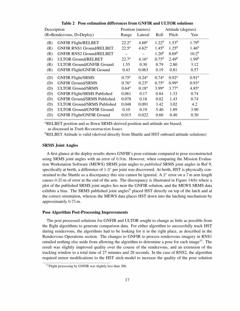
Table 2 Pose estimation differences from GNFIR and ULTOR solutionsDescription Position (meters) Attitude (degrees)(R=Rendezvous, D=Deploy) Range Lateral Roll Pitch Yaw
(R) GNFIR Flight/RELBET 22.2a 4.60a 1.22b 1.53b 1.79b
(R) GNFIR RNS1 Ground/RELBET 22.5a 4.62a 1.45b 1.25b 1.46b
(R) GNFIR RNS2 Ground/RELBET – – 1.20b 8.69b 10.2b
(R) ULTOR Ground/RELBET 22.7a 4.16a 0.75b 2.49b 1.99b
(R) ULTOR Ground/GNFIR Ground 1.55 0.30 0.79 2.80 3.12(R) GNFIR Flight/GNFIR Ground 0.43 0.063 0.19 0.81 0.57
(D) GNFIR Flight/SRMS 0.75a 0.24a 0.74a 0.92a 0.91a
(D) GNFIR Ground/SRMS 0.76a 0.23a 0.75a 0.99a 0.93a
(D) ULTOR Ground/SRMS 0.64a 0.18a 3.99a 3.77a 4.85a
(D) GNFIR Flight/SRMS Published 0.061 0.17 0.84 1.33 0.74(D) GNFIR Ground/SRMS Published 0.078 0.18 0.82 1.43 0.74(D) ULTOR Ground/SRMS Published 0.048 0.091 3.42 3.02 4.2(D) ULTOR Ground/GNFIR Ground 0.10 0.19 5.40 1.89 3.90(D) GNFIR Flight/GNFIR Ground 0.015 0.022 0.60 0.40 0.30
aRELBET position and as flown SRMS-derived position and attitude are biased,as discussed in Truth Reconstruction Issues
bRELBET Attitude is valid (derived directly from Shuttle and HST onboard attitude solutions)
SRMS Joint Angles
A first glance at the deploy results shows GNFIR’s pose estimate compared to pose reconstructedusing SRMS joint angles with an error of 0.9 m. However, when comparing the Mission Evalua-tion Workstation Software (MEWS) SRMS joint angles to published SRMS joint angles in Ref 9,specifically at berth, a difference of 1-3◦ per joint was discovered. At berth, HST is physically con-strained to the Shuttle so a discrepancy this size cannot be ignored. A 2◦ error on a 7 m arm lengthcauses 0.25 m of error at the end of the arm. The discrepancy is illustrated in Figure 14(b) where aplot of the published SRMS joint angles lies near the GNFIR solution, and the MEWS SRMS dataexhibits a bias. The SRMS published joint angles9 placed HST directly on top of the latch and atthe correct orientation, whereas the MEWS data places HST down into the latching mechanism byapproximately 0.75 m.
Pose Algorithm Post-Processing Improvements
The post processed solutions for GNFIR and ULTOR sought to change as little as possible fromthe flight algorithms to generate comparison data. For either algorithm to successfully track HSTduring rendezvous, the algorithms had to be looking for it in the right place, as described in theRendezvous Operations section. The changes to GNFIR to process rendezvous imagery in RNS1entailed nothing else aside from allowing the algorithm to determine a pose for each image††. Theresult was slightly improved quality over the course of the rendezvous, and an extension of thetracking window to a total time of 27 minutes and 28 seconds. In the case of RNS2, the algorithmrequired minor modifications to the HST stick-model to increase the quality of the pose solution
††Flight processing by GNFIR was slightly less than 3Hz
17
using available features, and a modification to the acquisition to compensate for the shifted ren-dezvous trajectory. With these modifications, the algorithm was able to track for 1 minute and 43seconds. No modifications were necessary to reprocess RNS3 imagery for deploy. The result was atracking window of 18 minutes and 39 seconds.
Regarding ULTOR, the AOS team discovered a software bug in the tracking mode that resultedin losing the track of HST midway through the RNS1 imagery on rendezvous. When corrected, UL-TOR was able to track HST using rendezvous imagery for 20 minutes and 20 seconds. For deploy,AOS discovered that features selected from the training data, and their subsequent filters, were notoptimal given the size of HST in the FOV of RNS3. Most of the features selected were associatedwith the center docking target. The training data used to develop these filters did not adequatelymodel the lighting conditions, reflectivity and contrast encountered on-orbit. This resulted in onlytwo or three features providing the tracking information, and ULTOR requires at least four featuresto produce a 6DOF pose estimate. To resolve this, ULTOR was placed into a higher resolution win-dowing mode for enhancing features on the target. This mode was not included in the flight versionof the software. To create a post-processed solution, AOS modified the training imagery to moreaccurately reflect the actual contrast of the SCM features and enabled the windowing mode. Thisresulted in a consistent track of HST for 10 minutes and 44 seconds at the RIP position using deployimagery.
Ground Results
In light of the issues with the flight data provided by the Shuttle, we are unable to provide atruly independent measure of the relative position of the Shuttle and HST. We now utilize theGNFIR post-processed solution as a measurement of the relative position. Figure 16(a) shows acomparison of the GNFIR flight pose and the ULTOR post-processed pose solutions to the GNFIRpost-processed solution during rendezvous. This data shows improvement in the position differ-ences. The RSS position error in Table 2 gives an error of 0.43 m in range for GNFIR and a 1.55 merror for ULTOR. Comparing these to the desired accuracy given in Table 1 of 1 m, GNFIR is bet-ter than the requirement, but ULTOR exceeds it. Figure 17(a) shows a comparison of the attitudesolutions of the pose sources to the RELBET attitude solution using the principal angle between thetwo quaternion solutions. For rendezvous, we see for the GNFIR solutions, errors of 1.5◦ per axisfrom Table 2 and a total principal angle of 2.5◦, and for the ULTOR solution, the accuracy resultedin 5◦ in roll and 2.5◦ for pitch/yaw from Table 2. Both solutions are much better than the desiredaccuracy of 15◦ stated in Table 1.
RNS2 is not presented in these plots due to the short time tracking window, but results weretabulated against the Postflight Attitude and Trajectory History (PATH) attitude solution. Theseerrors of 1.2◦ in roll and greater than 8◦ in pitch and yaw did not meet the desired accuracy of 5◦ inTable 1. This again is due to the poor on-orbit lighting conditions as shown in Figure 12.
Figures 16(b) and 17(b) show comparisons of the deploy pose solutions. In the case of position,the GNFIR flight pose solution and the ULTOR pose solution are compared to the GNFIR post-processed solution. We see here that the error between the two GNFIR solutions is much smaller at5 cm or less, whereas the ULTOR solution shows errors of 0.2 m. When compared to the publishedjoint angles, the position solutions for both GNFIR and ULTOR show differences less than 10 cm.These differences are on par if not better than the desired accuracy of 0.1 m stated in Table 1. Incomparing attitude solutions in Figure 17(b), we see less than 1◦ error for both sets of GNFIR posesolutions, however ULTOR shows a 7◦ error from the reconstructed pose solution from SRMS joint
18

16:20 16:25 16:30 16:35 16:400
0.5
1
1.5
2
2.5
3
3.5
4
4.5
5
GMT Time [HH:MM]
Po
siti
on
RS
S [
m]
GNFIR
F
ULTORG
(a) Rendezvous
11:25 11:30 11:35 11:40 11:45 11:500
0.05
0.1
0.15
0.2
0.25
0.3
0.35
0.4
GMT Time [HH:MM]
Po
siti
on
RS
S [
m]
GNFIR
F
ULTORG
(b) Deploy
Figure 16 Position Comparison of GNFIR post-processed solution to GNFIR flightdata and ULTOR post-processed solution
16:20 16:25 16:30 16:35 16:40 16:45 16:500
1
2
3
4
5
6
7
8
GMT Time [HH:MM]
Φ [
deg
]
GNFIR
F
GNFIRG
ULTORG
(a) Rendezvous
11:25 11:30 11:35 11:40 11:45 11:500
1
2
3
4
5
6
7
8
9
10
GMT Time [HH:MM]
Φ [
deg
]
GNFIR
F
GNFIRG
ULTORG
(b) Deploy
Figure 17 Principal Angular Differences between Shuttle BET and GNFIR flight,GNFIR post-processed, and ULTOR post-processed
angles. The GNFIR solution is well under the desired accuracy of 1◦ and 5◦ for roll and pitch/yaw,respectively, from Table 1, however ULTOR exceeds the desired with a 4◦ difference in roll and a6.14◦ difference in pitch/yaw.
A final note regarding the results presented here regards the accuracy of these relative measure-ments. The alignment of the RNS system to the Shuttle Atlantis can only be determined to approx-imately a degree. The alignment error of the RNS system to the MULE is well documented anddetermined to be 0.05◦. However, it was not possible to measure the alignment of the MULE to theShuttle, but it is assumed to be on the order of one degree at worst.
CONCLUSIONSThe RNS system met its goal of imaging, recording and computing pose estimates of HST dur-
ing its rendezvous with and deploy from Shuttle Atlantis for the SM4 mission. The GNFIR pose
19
o
• tI " " II
'"
0
• 0
• •
I 0
I J
0 __ , 0
• .'
•
o

algorithm tracked HST on rendezvous for 20 minutes and 27 seconds with a peak solution qualityof 99.2 %. During the deploy sequence, GNFIR tracked HST for a total of 15 minutes and 31 sec-onds with a peak quality of 87.1 %. The inability of the ULTOR algorithm to track HST duringrendezvous is linked to the RNS system not being configured for the change in the relative trajec-tory detailed in the Rendezvous Operations section. In the case of the deploy sequence, AOS’soversight to not include the windowing mode in the ULTOR flight algorithm resulted in a lack ofon-orbit tracking. However, in post-processing ULTOR was able to track HST for 20 minutes and20 seconds using rendezvous imagery, and 10 minutes and 44 seconds using deploy imagery.
In determining the accuracy of the pose solutions, several issues arose in reconstructing truthdata. The best estimated trajectory provided by the Shuttle program includes a 20 m error duringrendezvous due to issues with the Rendezvous Radar, and a 0.75 m error during the deploy sequencefrom joint angle measurements of the SRMS. The attitude solutions using the PATH solution andSRMS joint angles offers a much better comparison.
Therefore, to determine position accuracy, it was necessary to use a post-processed solution fromthe GNFIR algorithm. This comparison resulted in range errors during rendezvous of 0.43 m forGNFIR and 1.55 m for ULTOR. Note that the peak quality for the GNFIR post-processed solutionwas 99.2 %. These results were in the regime of the desired accuracy given in Table 1 of 1 m. Inthe case of attitude errors during rendezvous, comparisons to the PATH data show an error of 2.4◦
RSSfor GNFIR and an error of 3.27◦ RSS for ULTOR. These values are well below the desiredaccuracy of 15◦.
For the deploy comparison using RNS3, again the GNFIR post-processed solution was utilizedto compare position estimates. Comparison to GNFIR flight data resulted in less than 5 cm errorin position while ULTOR resulted in a 0.2 m error in position. The peak GNFIR quality for thepost-processed solution was 87.1 %. Regarding attitude accuracy, the GNFIR solutions show a lessthan 1◦ principal angle error, while the ULTOR data shows a 7◦ error in the principal angle. Thisprincipal angle error is an error generated by comparing quaternions. The desired accuracy for theshort range camera, RNS3, was given in Table 1 as 1◦ in roll and 5◦ in pitch/yaw. From Table 2,GNFIR meets these easily, however ULTOR, with errors larger than 5◦ Root Sum Squared (RSS)does not.
There is no denying the overall success of the RNS experiment on STS-125. When delving intothe detailed comparison data, the success is somewhat tempered by the comparison to truth butwas sufficient to meet the project’s stated goals (Table 1). The lessons learned on RNS are directlyapplicable to future AR&D scenarios and the collected data is a valuable asset for pose algorithmdevelopment.
REFERENCES
[1] B. J. Naasz, R. D. Burns, S. Z. Queen, J. V. Eepoel, J. Hannah, and C. E. Skelton, “THE HST SM4 RELATIVE NAV-IGATION SENSOR SYSTEM: OVERVIEW AND PRELIMINARY TESTING RESULTS FROM THE FLIGHTROBOTICS LAB,” Proceedings of the AAS F. Landis Markley Astronautics Symposium, No. AAS 08-280, Cam-bridge, Maryland, USA, 2008.
[2] “STS125/STS-400 Rendezvous Flight Data File,”[3] C. Harris, Active Vision, ch. 4, Tracking with Rigid Models. MIT Press, 1991.[4] T. Drummond and R. Cipolla, “Real-Time Visual Tracking of Complex Structures,” IEEE Transactions on Pattern
Analysis and Machine Intelligence, 2002.[5] J. Kelsey, J. Byrne, M. Cosgrove, S. Seereeram, and R. Mehra, “Vision-Based Relative Pose Estimation for Au-
tonomous Rendezvous and Docking,” 2006.
20

[6] S. J. Hannah, “ULTOR Passive Pose and Position Engine for Spacecraft Relative Navigation,” Proceedings of SPIE,Vol. 6958, Bellingham, WA, USA, 2007, pp. 69580I–1 to 69580I–10.
[7] P. S. Kwong, “Space Program Operations Contract: Internal ICD: RELBET Product,” Navigation Group of the FlightDesign and Dynamics Department of United Space Alliance Company, 2006.
[8] P. S. Kwong, “Space Program Operations Contract: Internal ICD: PATH Product,” Navigation Group of the FlightDesign and Dynamics Department of United Space Alliance Company, 2007.
[9] Johnson Space Center, Mission Operations Directorate EVA, Robotics, & Crew Systems Operations Division, PDRSOperations Checklist: STS-125 Flight Supplement, September 2008. JSC-48040-125.
21

ACRONYMS AND ABBREVIATIONS
6DOF Six Degree of Freedom
AR&D Autonomous Rendezvous and Docking
AGC Automatic Gain Control
AOS Advanced Optical Systems
COAS Crewman Optical Alignment Sight
FOV Field of View
FSS Flight Support Structure
Geomod Geometry Modeling Tool
GMT Greenwich Mean Time
GNFIR Goddard Natural Feature Image Recognition
GPS Global Positioning System
GSFC Goddard Space Flight Center
HST Hubble Space Telescope
HRSDM Hubble Space Telescope Robotic Servicing and De-orbit Mission
ICD Interface Control Document
IMU Inertial Measurement Unit
JSC Johnson Space Center
KSC Kennedy Space Center
MEWS Mission Evaluation Workstation Software
MET Mission Elapsed Time
MULE Multi-use Logistic Equipment Carrier
MSM Mass Storage Module
NASA National Aeronautics and Space Administration
P3E Passive Pose and Position Engine
PATH Postflight Attitude and Trajectory History
Phillum Physical Illumination
POCC Payload Operations Control Center
RELBET Relative Best Estimate Trajectory
22
RGT RNS Ground Terminal
RIP RNS Intermediate Position
RMS Root Mean Square
RNS Relative Navigation Sensor
RNS1 RNS Camera 1 (long range)
RNS2 RNS Camera 2 (medium range)
RNS3 RNS Camera 3 (short range)
RPOD Rendezvous Proximity Operations and Docking
RSS Root Sum Squared
SCM Soft Capture Mechanism
SM4 Servicing Mission 4
SMIT Servicing Mission 4 Integrated Timeline
SRMS Shuttle Remote Manipulator System
STOCC Space Telescope Operations Control Center
TM Telemetry Module
ULTOR ULTOR P3E
VIM Video Interface Module
VHDL VHSIC hardware description language
23