flir thermovision cm training · pdf fileversion 1.0.0 1 flir thermovision cm training this...
TRANSCRIPT

Version 1.0.0
1
FLIR ThermoVision CM training This manual is starting off with a quick instruction on how to start the system and after that there are
instructions on how to make your own software and modify the FLIR made program. If you are only
interested in demonstrating the ThermoVision CM for a potential end user, the first few pages should
be enough.
FLIR ThermoVision CM ............................................................................................................................ 1
Demonstrating the ThermoVision CM ................................................................................................ 3
Making sure the connected AX8 has the correct IP address ........................................................... 6
Diving into the HMI/SCADA Development software (WideQuick Designer) ...................................... 7
Part 1 ............................................................................................................................................... 7
Part 2 ............................................................................................................................................. 11
Part 3 ............................................................................................................................................. 15
Diving into the Video Management Software (Ethiris) ..................................................................... 22
Ethiris Admin & Ethiris Client ........................................................................................................ 22
Connecting to an Ethiris server from WideQuick .......................................................................... 24
Diving into the source code of the ThermoVision CM software (WideQuick Designer) ................... 26
Part 1 ............................................................................................................................................. 26
Part 2 ............................................................................................................................................. 27
Part 3 ............................................................................................................................................. 29
Challenge 3 .................................................................................................................................... 30

Version 1.0.0
2

Version 1.0.0
3
Demonstrating the ThermoVision CM To connect to the ThermoVision CM (TV CM) as a customer would use it we can either treat it as an
ordinary computer and connect a monitor, keyboard and mouse to it. Or we can use WideQuick
Remote which is a small software that is used to connect to the TV CM with from a remote computer.
The WideQuick Remote is basically a client software connecting to the TV CM server. The image below
illustrates two different setups. The computer in the image could be your laptop or a few monitors
connected to a desktop computer.
Connecting via a computer has the advantages that you can connect multiple computers to your TV
CM and it mimics an industrial control room. Connecting a VGA cable directly to the TV CM also
requires that you bring a monitor with you, and that is not always possible. To connect to the TV CM
from a computer, follow the steps below.
1) Install WideQuick Remote and WideQuick Designer on your laptop. This software doesn’t
require a license. The Designer software is not needed right now but convenient for the future.
Do not install the WideQuick Runtime program as this requires a license. It is important that
you install version 7.02 and not a newer version of any WideQuick software.
2) The TV CM as default has the IP address 192.168.254.10. To connect to it, your computer needs
to have an IP address in the same range. So assign the IP address 192.168.254.123 to your
laptop. Instructions on changing your computer IP address are below.

Version 1.0.0
4
a. Start the Control panel, go to Network and Sharing Center and then press Change
adapter settings.
b. Right click your LAN connection and press Properties.
c. Enter your computer credentials.
d. Select Internet Protocol Version 4 and press Properties.
e. Assign your computer the settings as seen below.

Version 1.0.0
5
f. Press OK and then Close. Wait at least 10 seconds until the IP settings are “stuck”.
3) Now your computer is on the same subnet as the TV CM and you have installed all the software
you need. To start the program, go to Start menu -> All Programs -> Kentima WideQuick ->
WideQuick Remote Startup.
4) Now you will see the startup screen where you are asked to enter the Start view. Press
Connect. Then chose the IP address 192.168.254.10 and the port 2122.
5) Login with the credentials admin/admin. Now you are in the TV CM software.
Click around within the software. Press the Help button if you need any help.

Version 1.0.0
6
Making sure the connected AX8 has the correct IP address The predefined camera settings are two A310 cameras with the IP addresses 192.168.254.11 and
192.168.254.12 and two AX8 cameras with the IP addresses 192.168.254.13 and 192.168.254.14. To
get data and video from an AX8, you therefor need to assign your AX8 to one of those IP addresses. To
assign an IP address to your AX8, follow the instructions below.
1) Start FLIR IP Config from Start menu -> All Programs -> FLIR Systems -> FLIR IP Config -> FLIR IP
Config.
’
2) Select your camera and then press the Settings button.
3) Assign the camera IP address to 192.168.254.14, the subnet to 255.255.255.0 and the gateway
to 192.168.254.10

Version 1.0.0
7
Diving into the HMI/SCADA Development software (WideQuick Designer) The software that is used to create the TV CM is called WideQuick Designer and is a development
software that is included when the customer buys the ThernoVision CM computer. To start the
designer software, you can either install WideQuick Designer on your own laptop or connect to the TV
CM computer with the Windows feature Remote Desktop. To connect via Remote Desktop, follow the
instructions below.
1. Go to the Start menu -> All programs -> Accessories -> Remote Desktop Connection
2. Write the IP address of the TV CM computer (192.168.254.10) and then press connect. Login
with the credentials admin/flir.
3. If you can’t connect, make sure your laptop is on an IP address on the same subnet, for
example 192.168.254.123. If it still doesn’t work, there might be IT security settings that need
to be changed. Try connecting a monitor to your TV CM instead and make sure it is working
correctly.
Now that you are “inside” the TV CM computer, you can treat your laptop as a keyboard, mouse and
monitor for the TV CM computer. The tutorial below is made to give the user a quick start and the goal
is that the user should be able to explore more advanced features afterwards on their own.
Part 1
Workviews
Start WideQuick Designer from the Start menu. It is located under Start -> All Programs -> Kentima
WideQuick -> WideQuick Designer. We will not create a small project with some basic functionality.
1. Create a new project by pressing File -> New Project.
2. Give the project a suitable name, if you want to you can chose a different directory than the
default folder.
3. The first thing you are asked to do once you’ve created the project is to create a workview. A
workview is basically a window or frame that is used to display your data to the user. Name
this workview “Start”.
Now you have created your first project and it contains a workview. It doesn’t look like much yet. But
now we will change the appearance a little bit.
1. Open the workview “Start” that you just created. Right click anywhere on the workview and
select Properties…

Version 1.0.0
8
2. From the Properties menu, select Appearance. Deselect “System color” and chose a new
background color. You can either provide a ARGB value or select a color from the color
selector. If you’d like you can choose an image as background.
If you provide a ARGB value, you need to use hexadecimal format where the first two values
represent the alpha channel which is how transparent the color is.
The transparency will not have any effect on the background though as there are no colors
behind the background. When you are done, press Apply and then OK.
3. Create a new workview and name it “Menu” by right clicking on the Workviews in the left
menu and press “Add workview…”.
4. Right click anywhere in the Menu workview and press Properties… Under the “Size and
Position” tab, modify the width and height to 640 in width and 480 in height. While you’re at
it, change the background color to any color you like. Press apply and then Ok.
Now you have successfully created two worviews with different sizes and backgrounds. They still don’t
contain any functionality, but we will soon change that.

Version 1.0.0
9
The box object
Now that you have created two workviews, we want to add some functionality and logic. You can start
the project from View -> Preview, or just press F5. Notice that the project will start and you will end
up at your Start workview. This is because the Start workview is selected to be the start view. You can
see this by looking at the figure left of the workview name. To close the preview, just click the cross in
the upper right corner like any ordinary window. It is possible to run the preview for 20 minutes; after
that it will close. This is because the WQ Designer doesn’t require a license.
If you would like to have the Menu workview as start view, just right click on the Menu workview title
and press “Set as start view for” -> All products. As we now know how to preview the project and we
have two workview, it is time to add some objects. You will start by adding a box.
1. Enter the Start workview and add a box by clicking the box icon and dragging it to the
workview.
2. The box is now added to the workview. The box is a simple object with which you can create
complex structures with. A little information about the tabs (the tabs are visible when you
select the box object) in the box objects are given below.
a. You can change the size, position and rotation from the Size and Position tab.
b. From the Line tab you can affect the contour of the box. It is also possible to use no
line if you don’t want the box to have any outline.
c. The gradient tab contains everything affecting the main color of the box. You can have
gradients, solid colors or a transparent box.

Version 1.0.0
10
d. From the action tab everything concerning what happens when you press on the box
is handled. You can configure what happens when the user performs various mouse
actions. A simple action is to open a new workview while more advanced actions might
be to execute some javascript code.
e. The security tab handles security, such as hiding the buttons for certain users.
f. The properties tab is usually empty from the beginning but it can contain variables
that is connected to other objects.
g. The dynamics tab shows all the dynamics connected to the box. It could for example
be the width of the box that is connected to the width of another box.
h. The variables tab is usually not used unless you have grouped together a few objects
and connected some variables to certain properties.
Play around with the different tabs and change some of them so that your box looks a
little more stylish, like the image below for example.
3. Now we will add some functionality to your styled box. Click on the box and go to the action
tab. Chose the Event: Click and select the checkbox “Link to workview”. Select the Menu
workview and remove the tick from “New window”.
4. Run the preview of your program and make sure that the Menu workview opens when you
press on the box.
Challenge 1
Time for a challenge! It is possible to add actions for almost every object. Try making the project close
when you click anywhere in the window. Now try to make the Menu workview open when you press
a keyboard button.

Version 1.0.0
11
Part 2
Adding dynamics to the box object
It is possible and very easy to add some dynamics to the box we’ve previously created. What we want
to do now is to connect some user action to a change in the box’s appearance.
1. Start by adding an ellipse to the Start workview.
2. Style it a little and then go to the Data Store in the left menu, from there double click Internals.
Here you can store variables used in your project. Add a variable by pressing Add. Name it deg
and make it an integer. Set the initial value to 0.
3. Go back to the Start workview, select your box and press the dynamics button next to the
rotation.
From the dynamics window, select the type Expression and type in the variable deg and press
Ok.

Version 1.0.0
12
4. Select the ellipse, go to the action tab and chose script as action for a mouse click. You can
write the script in the text field or open a script editor by pressing the icon to the right of the
field.
As script, write
deg = deg + 10;
This script will add 10 to the deg variable. Which means that every time the user clicks on the
ellipse, this script will run. What we have done is that we have connected the box’s rotation
to a variable which represents the rotation angle. When the user clicks on the ellipse, the box’s
rotation angle will increase.
5. Try the program by running the preview. If everything works the box will rotate when you
press the ellipse. If you want the box to rotate around its axis, you need to set the origin x and
origin y to center, this can be done from the size and position tab when the box is selected.
6. Modify the script so that the deg variable changes in a different way, for example you can write
deg = deg + 45;
Play around with the script a little. It is just ordinary Javascript so it is easy to search the web
for syntax issues and coding techniques.
Connecting a slider, text object and spin box to the box object
Now that we are familiar with the box and ellipse object, we can add a little more advanced objects,
the slider, the text object and the spin box. These objects are located in the same place as the box and
ellipse, just a little more to the right.
1. Go ahead and add a “Text”, “Slider” and “Spin box”to your workview Start.
2. As you see, the slider is a little different than the box and ellipse. It has a new tab which is
called slider. The text object and spin box also has new tabs, these ones are called text and
spin box. Under these tabs we will find settings which are exclusive for that kind of object.
3. We will start with the text object.
a. Make the font a little bigger, this can be done from the font tab. Here you can also
change the font color and style. If you want to change the background color from
transparent to some color you can change that under the Gradient tab.
b. The text that we want to display in this text object can either be some static text or
be connected to some dynamics. At first, we can write whatever we want in the Text
field and then try running the project.

Version 1.0.0
13
c. Now we want to add some dynamics to this text object. To do so, press the dynamic
button to the right of the text field, as indicated by the image below.
From the dynamics window we can add some type of dynamics to the text objects.
Go ahead and chose the type: Expression and select the deg variable found under
Variables -> Internals. This is very similar to the dynamics connected to the ellipse that
we configured earlier.
d. Go ahead and run the project and make sure that the text object is updated according
to the box’s rotation.
4. Now we can add some dynamics to the slider.
a. Select the slider and go to the slider tab. Here you see the variable connected to this
object. Select the variable deg, type integer, min 0 and max 360 according to the
image below.
b. Run the project and watch the slider change when you press the ellipse. Also try
sliding it and watch the box rotate.
5. It’s time to modify the spin box. Before you do so, you can arrange all the objects to a nice
design. Maybe something similar like the image below.
a. To connect the spin box to the deg variable, select the spin box and open the tab spin
box. This menu is very similar to the slider object, so go ahead and assign the deg
variable and the min and max values.
b. If you want, you can use any values you want as min and max. When the deg variable
has a higher value than the max value, it will saturate at the max value.

Version 1.0.0
14
c. Preview the project and make sure everything works as it should.
Challenge 2
Now you are ready for a challenge. We already have a way to go to the Menu workview from the Start
workview, but we want to have a little more intuitive way to access the Menu workview. Add whatever
object you want and add some dynamics so the user can interact with this object to reach the Menu
workview. In the Menu workview, add some object that will take the user back to the Start workview,
this could for example be an arrow.
Hint: if you select multiple objects and right click -> group, you will create one single object.

Version 1.0.0
15
Part 3
Graphs and data storage
It’s time to add some graphs to our project. Graphs can be uses to display data and how it changes
over time. It could be data from a thermal camera or any other sensor that we want to visualize.
1. Create a new workview and name it Graphs. Add an object in the Start workview that makes
it possible for the user to access the Graphs workview by clicking on this object. Make the size
of the Graphs workview to be the same size as the Start workview and when the user is
forwarded to the Graphs workview, it shouldn’t open in a new window.
1. Add an internal variable to the project and name it random_value. It should be an integer with
the initial value of 0.
2. In the Graphs workview, add a text object and go to the Text tab, click on the dynamics button.
3. Select the Type: Script and add the following script:
random_value = Math.random() * 100;
return random_value;
The function Math.random() returns a random value between 0 and 1. The resulting value will
therefore be an integer between 0 and 100. One might believe that this script will run one time and
then random_value will have that value forever. But as the graphics will be updated 10 times every
second, the random_value will be updated at a rate of 10 Hz.
4. Try it out by running the preview.
5. To change how often the script is executed, right click anywhere in the Graphs workview and
press Properties… Enter the Appearance tab and change the value of the Graphics refresh
time.

Version 1.0.0
16
You will of course not see any changes faster than your monitor refresh rate. Lowering the
WideQuick refresh rate is a good way to save computer processing power if there is no need
to have a fast application. If your thermal sensor for example only measures at 3 Hz, it is not
necessary to update the graphics more than this.
Now that we have a value that is constantly updated, we might say that we have a sensor simulator.
This random_value could for example be a temperature value from a spot in a thermal camera. Even
though the value isn’t that realistic. What would be good now is to save this data in some way. Luckily
WideQuick has some built in functionality for data storage.
1. To store data, we will use the Logger in WideQuick. This is located to the left. Right click on the
Loggers menu and press Add logger…
2. You can use different kind of loggers, we will use a cyclic logger which means that it stores
data at a given interval until it reaches a size threshold, then it will delete the oldest data with
new data.
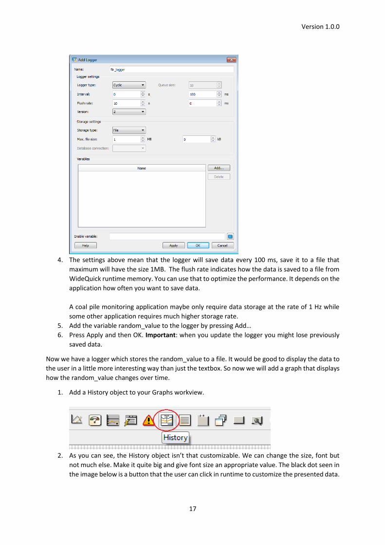
3. Name the logger flir_logger and use the settings seen below.
Version 1.0.0
17
4. The settings above mean that the logger will save data every 100 ms, save it to a file that
maximum will have the size 1MB. The flush rate indicates how the data is saved to a file from
WideQuick runtime memory. You can use that to optimize the performance. It depends on the
application how often you want to save data.
A coal pile monitoring application maybe only require data storage at the rate of 1 Hz while
some other application requires much higher storage rate.
5. Add the variable random_value to the logger by pressing Add…
6. Press Apply and then OK. Important: when you update the logger you might lose previously
saved data.
Now we have a logger which stores the random_value to a file. It would be good to display the data to
the user in a little more interesting way than just the textbox. So now we will add a graph that displays
how the random_value changes over time.
1. Add a History object to your Graphs workview.
2. As you can see, the History object isn’t that customizable. We can change the size, font but
not much else. Make it quite big and give font size an appropriate value. The black dot seen in
the image below is a button that the user can click in runtime to customize the presented data.

Version 1.0.0
18
If we don’t want to give the user too much freedom, we can remove this button by going to
the History tab and removing the tick from the “Settings button”.
3. Run the preview of your project and take a look at the history object that you’ve created. It
doesn’t look like much yet because we haven’t connected any data to it.
4. To connect data to the history object we need to go to the Analog tab of the history object.
From there, press the Add button and name the graph something fitting. Select the logger
flir_logger and Log value random_value.
5. Notice that there are no available Axis yet. To add an axis, go to the History tab and add a Y-
axis. Now you can go back to the Analog tab and select the Axis you just added.
6. Go ahead and run the program. If it doesn’t update itself, go back to the designer and go to
the History object history tab, and change the track interval to 1 second. Run the program
again. Now it should be continuously updated.
Alarms
Now it’s time to add some alarms. Alarms can be connected to temperature data from thermal
cameras, RPM’s from engines, pressure data from pressure sensors or any other kind of data available
in an industrial environment. WideQuick can get this data from Modbus or an OPC server. The alarms
are available under the Data Store menu to the left.
1. Add an alarm by double clicking the Alarms title. If you don’t have any previous alarms, you
will be asked to add a new alarm group.
2. Name the alarm group flir_alarm, press Apply and then OK.

Version 1.0.0
19
3. Enter the flir_alarm group and add a new row to the group. Name it flir_alarm and give
appropriate values to the rest of the fields.
a. Severity: This can be an arbitrary value. It is used to sort the alarms if you have many
alarms. For example, some alarms are more severe than others, then you want to see
that and be able to sort the alarms based on this.
b. Ack rule: There are three different acknowledgement rules. Normal means that the
alarm can be acknowledged at any time. Strict means the alarm can only be
acknowledged when it’s inactive. Auto means that the alarm is acknowledged
automatically as soon as it becomes inactive, but may also be manually acknowledged
before that.
c. Text: This is the text that will be displayed when the alarm is active.
d. Details: Text that is displayed when the alarm is clicked on from an alarm list.
e. Activation condition: This is the most important setting of an alarm. Here you
configure the conditions that will raise the alarm.
You can connect the alarm to a variable, which means that the alarm with go off when
that variable is true. This variable need to be of a Boolean type. We will use a logical
statement for our alarm, so go ahead and connect the random_value to this alarm. Set
it to be greater than 95. As the random_value will have random values between 0 and
100, a value of 95 will most likely happen every now and then. Other activator
conditions can be Filter bit, where the alarm goes off when your filtered bit from a
variable is set. You can also use a script. When the script returns true, the alarm will

Version 1.0.0
20
be activated. But for this alarm, use the logical statement according to the image
above.
4. Go back to the Start workview and add an Alarm object.
Select the alarm object and go to the tab Alarm, add the flir_alarm to your list of groups.
5. The Alarm type can be five different types. Try them all and try understanding the difference.
When the list type is used, the alarm can be acknowledged by double clicking on it.
Challenge 3
Add a new alarm in the same alarm group but this time try making it function the same way as the
previous alarm but base it on a script instead of on a logical statement.

Version 1.0.0
21
Hint: The script should return true when the alarm should be activated, otherwise it should return
false.

Version 1.0.0
22
Diving into the Video Management Software (Ethiris) Ethiris VMS is a video monitoring software that can be used for applications where video surveillance
is needed. The software alone is used by many customers, but it is also possible to use the video server
functionality of the software together with the WideQuick HMI/SCADA interface. This short tutorial
aims to give the reader an introduction of the software Ethiris Admin, Ethiris Client and how to connect
Ethiris with WideQuick. Instructions on how to install the software and the licensing is handled in other
tutorials.
Ethiris Admin & Ethiris Client Ethiris Admin is the software used for configuring the server and clients. The Ethiris server is not an
ordinary program, it runs as a service under the operating system and starts automatically when the
computer starts. It is recommended to have a dedicated computer for the server. The TV CM computer
is an example of this.
1. Start Ethiris Admin, it is located under Start -> All Programs -> Kentima Ethiris -> Ethiris Admin.
2. In the left menu you have the Ethiris Components which are the Server and client. Not
surprisingly the server is used for configuring the server and the client is used for configuring
the client.
To get going, expand the Ethiris Server.
3. Navigate to the Cameras menu. The factory configuration includes 4 cameras configured to
have the IP addresses 192.168.254.11-192.168.254.14, if you want to change the IP address of
a camera, you do that from here.
It is possible to use either a AX8 or a A310 camera from FLIR. We can start the Ethiris Client by
expanding the client menu and then clicking according to the image below.

Version 1.0.0
23
This will open the client program and if your camera is properly connected you will see the video
stream.
4. Close the client program and go to the Views menu and add a new section.
5. Name it mySection. A section is part of the client configuration which contains multiple views.
If you for example use Ethiris in a big shopping mall, each floor might have its own section and
each shopping store its own view.
6. Under your new section, add a view.

Version 1.0.0
24
7. Open the layout under your new view. Create a 2x2 view. To select a camera stream for each
column and row, select the area and then chose a camera to the right.
8. In the area to the bottom right, we will create a hotspot camera. This means that this area will
be able to display different video streams depending on the user. To do so, right click in the
bottom right area and press Type -> Hotspot
Select the bottom right area and then tick the “Click” check box for all cameras.
9. Save your configuration with CTRL+S and then run the client program.
Connecting to an Ethiris server from WideQuick It is possible to connect to the video streams from cameras in an Ethiris server from within your
WideQuick program. To test this feature we will use a blank WideQuick project and add some simple
logic.
1. Start WideQuick Designer on the same computer as the computer running the Ethiris server.
2. Create a new project. From your start workview, add an EthirisView.
3. Make the size of the EthirisView to be 640 by 480 pixels. This is the same dimensions as the
AX8 image stream.
4. Right click the Ethiris Server menu to the left and press Add Ethiris Server…

Version 1.0.0
25
5. Give the server the same name as the Ethiris server has and provide the local IP address. If you
use WideQuick on a different computer than Ethiris, you need to know the Ethiris IP address.
6. Press Apply and OK.
7. Go to your EthirisView and select the Ethiris View tab, chose the Server and type the camera
name. You need to type it as WideQuick doesn’t know the camera name yet.
8. Preview the project and make sure you see the live stream.
Now that we know how to view the video stream from the Ethiris server, we can add some more
functionality. We will add a freeze and resume button.
1. Add two button objects to your workview.

Version 1.0.0
26
2. Give them a nice design and then go to the Button Tab. Set the caption-up to Freeze on one
button and Resume on the other button.
3. Select the Resume button and go to the action tab. Select Script as event. Use this script:
this.view.EthirisView1.startLive();
Do the same with the Freeze button, but use this script instead:
this.view.EthirisView1.stop();
4. Preview the program.
Diving into the source code of the ThermoVision CM software (WideQuick Designer) The TV CM software is a WideQuick program made to show what is possible to do with FLIR cameras
together with WideQuick and Ethiris. This tutorial is intended to give the reader an understanding of
the WideQuick project and the goal is that the user should be able to make any changes they desire
and still have a functioning project.
Part 1
Opening the project for editing
The project is located on the ThermoVision CM computer in the folder
C:\Users\admin\Documents\WideQuick Projects
1. Start WideQuick Designer and open the ThermoVision CM project.
2. Save it under a different name so you don’t make any unwanted mistakes on the project.
3. Make sure the program works by running the preview.

Version 1.0.0
27
4. The Login workview is assigned to be the start workview. The security can be bypassed quite
easily by just changing the start workview to be “Workview1”. Do this and run the program.
With this change, you don’t need to login. It is possible to do much better security functions
than the one in this project.
5. Make sure that you understand the functionality of the program.
6. Most likely there are some bugs. All bugs should be reported so FLIR can fix them for the next
release.
Understanding the Multiviewer
The Multiviewer is a very useful object in WideQuick. It can be used for displaying workviews within
another workview. You can see it as a container for data. If you are familiar with HTML, it is comparable
to the IFrame.
1. Open the workview Workview1 and make it the start workview if you haven’t done it already.
2. Look at the structure of the page. You have the buttons on top and then a big Multiviewer
covering most of the page. Select the Multiviewer and press the Multiviewer tab, there you
have the Index property. This property determines which workview that is showed in the
Multiviewer. The index is connected to a variable, this variable is found under the dynamics
button accessible as seen in the image below.
3. Press the dynamics button and understand which variable that is connected to the index value.
4. Take a look at the buttons (Video, Analysis etc.) and see what happens when you press on
them. Hint: look under the action tab.
Challenge 1
Create a new workview and add a button to the start workview. When the user clicks the button, the
Multiviewer should show the new workview.
Part 2
Understanding the alarms
The alarms in the TV CM solution is based on scripts. Each camera has its own alarm group with 18
alarms. The activation scripts are found under the activation column.

Version 1.0.0
28
1. Double click on the activation column and then press the script button:
2. The script is quite short and essentially it is based on value from the camera, the values entered
by the user and if the alarm should be enabled or disabled. Take a look at the code and try
understanding it:
if(Flir1.Unit1.Spot1 > cam1_spots_values[0])
{
if(cam1_spots_active[0])
{
return true;
}
}
return false;
3. As you see, the alarm is limited to the “above”-type of alarms. This will most likely be changed
in the future, either by FLIR or integrators making their own custom made project. Each camera
has some arrays making up the alarm logics. Take a look at the internal variables and
understand the connection with the alarm logics.

Version 1.0.0
29
Challenge 2
Modify the alarm conditions for camera 1, spot1 so that it is always enabled and is based on “below”
temperature type instead.
Part 3
Understanding Modbus in WideQuick
WideQucik supports Modbus connections with all Modbus compliant devices. This is perfect for the
AX8 and A310 cameras. The Modbus connections are handled from the Data Store menu.
In the picture above, there are four Modbus devices connected to this WideQuick project. The
communication between WideQuick and a Modbus device is independent of the Ethiris video server.
To access the Modbus configuration, right click on any of the FLIR cameras and press Properties…
From there you can edit the IP address of the camera. If you change the camera IP address, this setting
needs to be updated.
1. Open FLIR IP Config and change the IP address of your camera. Change it to 192.168.254.123.
2. Run the preview. Notice that nothing really works. You have no image stream and the
measurement data is not updated.
3. Now change the Modbus IP address and then run the preview once again. Your measurement
data should now be updated.
4. Change the internal variable corresponding to the camera IP address:

Version 1.0.0
30
These four strings only affect the camera labels and the links to the web interface.
5. To get the video stream working, you need to start Ethiris Admin and change the camera IP
address from there also.
Challenge 3 Create a new WideQuick Project and add a video stream and a textbox showing the value of Spot 1.
Hints: The ThermoVision CM project contains all the information you need. If you need script advice,
google is your friend (it is basically JavaScript).