floating point arithmetic - pldworld.comasim/...floating point arithmetic 1 introduction fixed point...
TRANSCRIPT

Floating Point Arithmetic
1 Introduction
Fixed point numbers suffer from limited range and accuracy. For a given word length
both fixed point and floating point representations give equal distinct numbers. The
difference is that in fixed point representation the spacing between the numbers is equal,
so smaller numbers when truncated or rounded give a much larger error than the larger
numbers. However floating point representation gives different spacing between
numbers. We get denser distances between numbers when the number is small and
sparser distance for larger numbers. So the absolute representation error increases with
larger numbers.
Floating point numbers are used to obtain a dynamic range for representable real numbers
without having to scale the operands. Floating point numbers are approximations of real
numbers and it is not possible to represent an infinite continum of real data into precisely
equivalent floating point value.
Number system is completely specified by specifying a suitable base , significand (or
mantissa) M, and exponent E. A floating point number F has the value
F=M E
is the base of exponent and it is common to all floating point numbers in a system.
Commonly the significand is a signed - magnitude fraction. The floating point format in
such a case consists of a sign bit S, e bits of an exponent E, and m bits of an unsigned
fraction M, as shown below
The value of such a floating point number is given by:
The most common representation of exponent is as a biased exponent, according to which
bias is a constant and Etrue
is the true value of exponent. The range of Etrue
using the e
bits of the exponent field is
Unsigned Significand MExponent ES
F 1– SM
E=
E Etrue
bias+=
The bias is normally selected as the magnitude of the most negative exponent; i.e. 2e-1
, so
that
The advantage of using biased exponent is that when comparing two exponents, which is
needed in the floating point addition, for example the sign bits of exponents can be
ignored and they can be treated as unsigned numbers
The way floating point operations are executed depends on the data format of the oper-
ands. IEEE standards specify a set of floating point formats, viz., single precision, single
extended, double precision, double extended. Table 1 presents the parameters of the
single and double precision data formats of IEEE 754 standard.
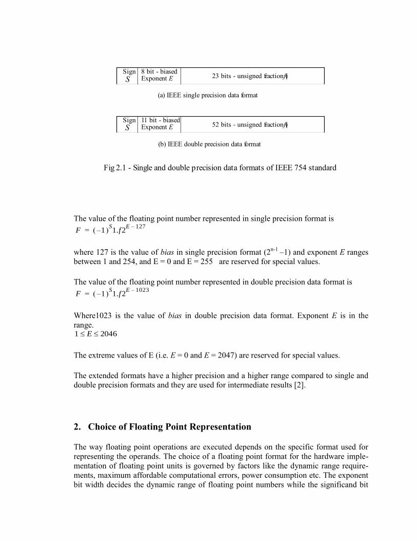
Fig.2 1 shows the IEEE single and double precision data formats. The base is selected as
2. Significands are normalized in such a way that leading 1 is guaranteed in precision (p)
data field. It is not the part of unsigned fraction so the significand is in the form 1.f. This
increases the width of precision, by one bit, without affecting the total width of the
format.
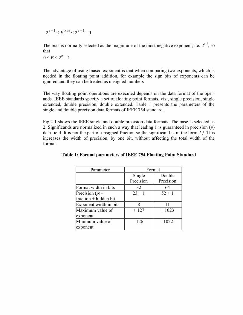
Table 1: Format parameters of IEEE 754 Floating Point Standard
Parameter Format
Single
Precision
Double
Precision
Format width in bits 32 64
Precision (p) =
fraction + hidden bit
23 + 1 52 + 1
Exponent width in bits 8 11
Maximum value of
exponent
+ 127 + 1023
Minimum value of
exponent
-126 -1022
2e 1–
Etrue
2e 1–
1– –
0 E 2e
1–
The value of the floating point number represented in single precision format is
where 127 is the value of bias in single precision format (2n-1
–1) and exponent E ranges
between 1 and 254, and E = 0 and E = 255 are reserved for special values.
The value of the floating point number represented in double precision data format is
Where1023 is the value of bias in double precision data format. Exponent E is in the
range.
The extreme values of E (i.e. E = 0 and E = 2047) are reserved for special values.
The extended formats have a higher precision and a higher range compared to single and
double precision formats and they are used for intermediate results [2].
2. Choice of Floating Point Representation
The way floating point operations are executed depends on the specific format used for
representing the operands. The choice of a floating point format for the hardware imple-
mentation of floating point units is governed by factors like the dynamic range require-
ments, maximum affordable computational errors, power consumption etc. The exponent
bit width decides the dynamic range of floating point numbers while the significand bit
(a) IEEE single precision data format
(b) IEEE double precision data format
Fig 2.1 - Single and double precision data formats of IEEE 754 standard
8 bit - biased Exponent E
Sign 23 bits - unsigned fraction (f)
11 bit - biased Exponent E
Sign 52 bits - unsigned fraction (f)
S
S
F 1– S1.f2
E 127–=
F 1– S1.f2
E 1023–=
1 E 2046
width decides the resolution. The dynamic range offered by floating point units is much
higher than that offered by fixed point units of equivalent bit width. Larger dynamic
range is of significant interest in many computing applications like in multiply -
accumulate operation of DSPs. But larger range is not needed in all the applications. The
actual bit-width required in many applications need not match with the ones provided by
IEEE standards. For example, considering the design of an embedded system, the choice
of IEEE data formats need not give optimal results. In some cases, even IEEE specified
rounding scheme may not guarantee acceptable accuracy. That means, depending on the
specifications of a certain application, dedicated system solutions can work with non
IEEE data formats as well as rounding schemes such that the real life input/output signals
satisfy the data processing goals required by the target application. Although custom
specification of floating point format do find some applications, in the recent years more
and more manufacturers are following IEEE standards for the design of their hardware.
IEEE compliance guarantees portability of software between different platforms.
Applications that do not need such portability need not stick to IEEE standards.
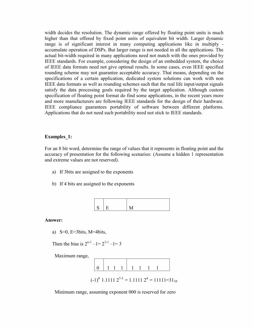
Examples_1:
For an 8 bit word, determine the range of values that it represents in floating point and the
accuracy of presentation for the following scenarios: (Assume a hidden 1 representation
and extreme values are not reserved).
a) If 3bits are assigned to the exponents
b) If 4 bits are assigned to the exponents
S E M
Answer:
a) S=0, E=3bits, M=4bits,
Then the bias is 2n-1
–1= 23-1
–1= 3
Maximum range,
0 1 1 1 1 1 1 1
(-1)0
1.1111 27-3
= 1.1111 24
= 11111=3110
Minimum range, assuming exponent 000 is reserved for zero

0 0 0 1 0 0 0 0
(-1)0
1.0000 2 1-3
= 1.0000 2-2
= 0.01=0.2510
b) S=0, E=4bits, M=3bits ,
Then the bias is 2n-1
–1= 24-1
–1= 7
Maximum range,
0 1 1 1 1 1 1 1
(-1)0
1.111 215-7
= 1.111 28
= 111100000= 48010
Minimum range, assuming exponent 000 is reserved for zero
0 0 0 0 1 0 0 0
(-1)0
1.0000 2 1-7
= 1.0000 2-6
= 0.000001=0.01562510
You must know that the total No. of numbers that can be represented is the same. The
difference between example (a) and example (b) is that the resolution of the numbers that
can be represented is different.
Exercise:
For a) above determine the decimal number corresponding to when M contains 0001 and
0010.
For b) above determine the decimal number corresponding to when M contains the
number 001 and 010.
Discuss the resolution of the numbers represented in (a) & (b).
Example_2
Represent 21.7510 in Floating point. Use the IEEE 754 standard.

Answer:
21.75 in binary is 10101.11 or 1.010111 24
S=0
Bias is 27-1=127 E= 127 + 4 = 131
1bit 8 bits 23 bits
0 1 0 0 0 0 011 0 1 0 1 1 1 0 0 0 0 0 0 0 0 0 0 0 0 0 0 0 0 0
Example _3
Represent -0.437510 in floating point, using IEEE standard 754
Answer:
Binary equivalent of –0.4375 = -.0111 or – 1.11 2-2
S= 1
Exponent is –2 + 127 =125 or 01111101
1bit 8 bits 23 bits
1 01 1 1 1 1 01 1 1 0 0 0 0 0 0 0 0 0 0 0 0 0 0 0 0 0 0 0 0 0
3 IEEE Rounding
All real numbers can not be represented precisely by floating point representation. There
is no way to guarantee absolute accuracy in floating point computations. Floating point
numbers are approximations of real numbers. Also the accuracy of results obtained in a

floating point arithmetic unit is limited even if the intermediate results calculated in the
arithmetic unit are accurate. The number of computed digits may exceed the total number
of digits allowed by the format and extra digits have to be disposed before the final
results are stored in user-accessible register or memory. When a floating point number
has to be stored or output on the bus, then the width of the memory and the bus dictates
that certain numbers greater than the width of the significand to be removed. Rounding is
the process of removing the extra bits with the digital system resulting from internal
computation (higher precision) to the exact bus width. IEEE 754 standard prescribes
some rounding schemes to ensure acceptable accuracy of floating point computations.
The standard requires that numerical operations on floating point operands produce
rounded results. That is, exact results should be computed and then rounded to the nearest
floating point number using the ‘round to nearest - even’ approach. But in practice, with
limited precision hardware resources, it is impossible to compute exact results. So two
guard bits (G and R) and a third bit, sticky (S), are introduced to ensure the computation
results within an acceptable accuracy using minimum overhead.
The default rounding mode specified by the IEEE 754 standard is round to nearest - even.
In this mode, the results are rounded to the nearest values and in case of a tie, an even
value is chosen. Table 2.2, shows the operation of round to nearest - even, for different
instances of significand bit patterns. In this table, X represents all higher order bits of the
normalized significand beyond the LSBs that take part in rounding while the period is
Table 2.2: Round to nearest - even rounding
Significand Rounded
Result
Error Significand Rounded
Result
Error
X0.00 X0. 0 X1.00 X1. 0
X0.01 X0. - 1/4 X1.01 X1. - 1/4
X0.10 X0. - 1/2 X1.10 X1. + 1 + 1/2
X0.11 X1. + 1/4 X1.11 X1. + 1 + 1/4
separating p MSBs of the normalized significand from round (R) and sticky (S) bits. It
can be seen from the table that the average bias (which is the average of the sum of errors
for all cases) for the round to nearest scheme is zero. Fig 2.2 illustrates the relative
positions of the decision making bits. Rounding to the nearest value necessitate a
conditional addition of 1/2 ulp (units in the last place). The decision for such addition can
be reached through the evaluation of the LSB (M0) of the most significand p bits of the
normalized significand, the round (R) bit and the sticky (S) bit. Rounding is done only if
condition R.(M0 +S) is true (Boolean).

Example:
Round the following data structure, according to the nearest even
M0 R S
0 01 1 1 1 1 01 1 1 0 0 0 0 0 0 0 0 0 0 0 0 0 0 0 0 0 0 0 0 1 1 1
Answer:
Since R(M0 + S ) holds, then, the rounding will produce the following results:
0 01 1 1 1 1 01 1 1 0 0 0 0 0 0 0 0 0 0 0 0 0 0 0 0 0 0 0 1 0
4 Floating Point Multiplication
The algorithm of IEEE compatible floating point multipliers is listed in Table 2.3. Multi-
plication of floating point numbers F1 (with sign s1, exponent e1 and significand p1) and
F2 (with sign s2, exponent e2 and significand p2) is a five step process. Its flow chart is
presented in Fig 2.3 [2].
Figure 2.2 - Normalized Significand before rounding
p - 1 higher order bits M0 R S
p bit significand field
Sticky bit
Round bit

Table 2.3: Floating point multiplication algorithm
Step 1
Calculate the tentative exponent of the product by adding the biased exponents
of the two numbers, subtracting the bias. The bias is 127 and 1023 for
single precision and double precision IEEE data format
respectively e1 e2 bias–+
Step 2
If the sign of two floating point numbers are the same, set the sign of product to
‘+’, else set it to ‘-’.
Step 3
Multiply the two significands. For p bit significand the product is 2p bits wide
(p, the width of significand data field, is including the leading hidden bit (1)).
Product of significands falls within range: 1 product 4 Step 4
Normalize the product if MSB of the product is 1 (i.e. product of two
significands), by shifting the product right by 1 bit position and
incrementing the tentative exponent. significands 2 Evaluate exception conditions, if any.
Step 5
Round the product if R(M0 + S) is true, where M0 and R represent the pth and
(p+1)st bits from the left end of normalized product and Sticky bit (S) is the
logical OR of all the bits towards the right of R bit. If the rounding condition is
true, a 1 is added at the pth bit (from the left side) of the normalized product.
If all p MSBs of the normalized product are 1’s, rounding can generate a carry-
out. In that case normalization (step 4) has to be done again.
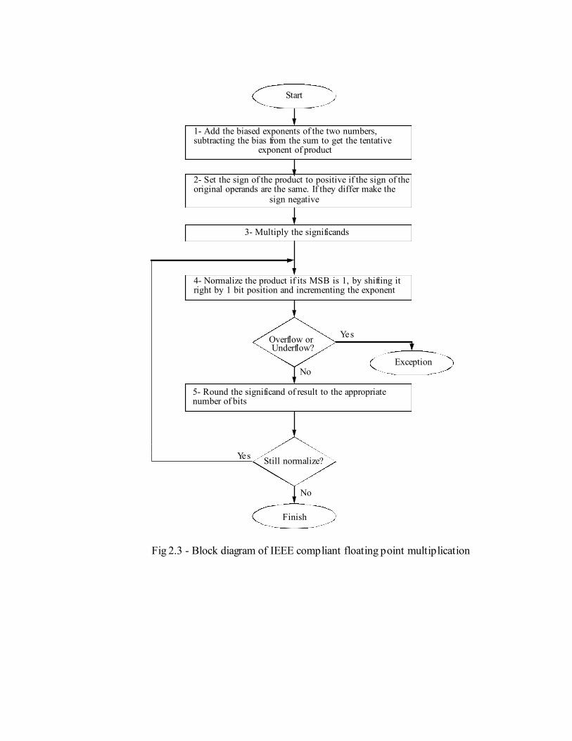
1- Add the biased exponents of the two numbers,
2- Set the sign of the product to positive if the sign of the
3- Multiply the significands
Start
4- Normalize the product if its MSB is 1, by shifting it
Overflow orUnderflow?
5- Round the significand of result to the appropriate
Finish
Exception
Still normalize?
subtracting the bias from the sum to get the tentativeexponent of product
original operands are the same. If they differ make the sign negative
right by 1 bit position and incrementing the exponent
Fig 2.3 - Block diagram of IEEE compliant floating point multiplication
number of bits
No
Yes
No
Yes

Fig 2.4 illustrate the process of significand multiplication, normalization and rounding.
Example:
Multiply the following two numbers. Use IEEE 754 standard:
A= 25.510 B= -0.37510
Answer:
A can be represented as A= 1.10011 * 24
or exp= 127+ 4 = 13110, Sig =1.10011, S=0
B can be represented as B= 1.1 * 2-2
or exp= 127 -2= 12510 , sig =1.1 , S=1
Add exponent and subtract bias
Exponent = 1 0 0 0 0 01 1 + 0 1 1 1 1 1 0 1 - 0 1 1 1 1 1 1 1 = 1 0 0 0 0 0 0 1
Multiply Significands 1.1 0 0 1 1 0 0 0 0 0 0 0 0 0 0 0 0 0 0 0 0 0 0 *
1.1 0 0 0 0 0 0 0 0 0 0 0 0 0 0 0 0 0 0 0 0 0 0
10.0110010000000000000000000000000000000000000
Now round the results.
Figure 2.4 - Significand multiplication, normalization and rounding
p-bit significand field
Cout
Result of significand multiplication before normalization shift
}
R SM0
p - 1 higher order bits
Normalized product before Rounding
InputSignificands
2p bits
1 p - 1 lower order bits
p - 1 lower order bits1
Significands before multiplication
p-bit significand field
0 1 0 0 0 0 01 1 1 0 0 1 1 0 0 0 0 0 0 0 0 0 0 0 0 0 0 0 0 0 0
1 0 1 1 1 1 1 0 1 1 0 0 0 0 0 0 0 0 0 0 0 0 0 0 0 0 0 0 0 0 0 0

After rounding we get: 10. 01100100000000000000000
After normalization we get: 1. 0 0110010000000000000000 * 21
New exponent after normalization 1 0 0 0 0 0 0 1 + 0 0 0 0 0 0 0 1 = 1 0 0 0 0 0 1 0
Final result
Unbiased value of exponent is 1000 0010 -0111 1111 = 0000-0011 ie (130-127 =3)10
A * B = 1. 0011001 * 23 = -9.562510
Multiplier Architecture A simple multiplier architecture is shown below:
The exponent logic is responsible for extracting the exponents and adding them and
subtracting the bias. The Control/Sign logic, decodes the sign bit (EXOR) and directs the
significands to the integer multiplier.
The results of the significands multiplication is rounded by the rounding logic and if
necessary is normalized through a shift operation. The exponent in updated by the
exponent increment block and the final results, are presented to the output logic. This
architecture is shown in figure below
1 1 0 0 0 0 0 1 0 0 0110 010 0 0 0 0 0 0 0 0 0 0 0 0 0 0 0
Exponent Sign Logic Significand Multiplier
Roundin
g Logic
Normalization Logic
Correction Shift
Resul
t Selector
Result Flags Logic
Significand1 Significand2 Exp1 Exp2 Sign1
Sign2
IEEE Product Flag
s
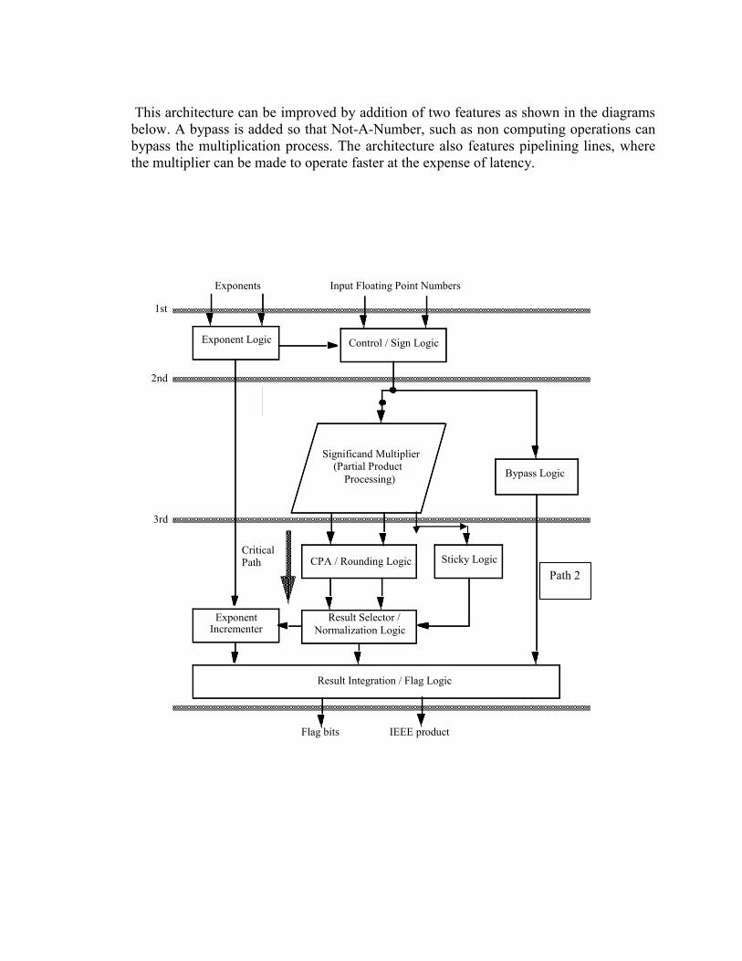
This architecture can be improved by addition of two features as shown in the diagrams
below. A bypass is added so that Not-A-Number, such as non computing operations can
bypass the multiplication process. The architecture also features pipelining lines, where
the multiplier can be made to operate faster at the expense of latency.
Control / Sign Logic
CPA / Rounding Logic
Result Selector / Normalization Logic
Exponent Logic
Significand Multiplier (Partial Product Processing)
Result Integration / Flag Logic
Exponent Incrementer
Sticky Logic
Exponents
IEEE product Flag bits
Input Floating Point Numbers
Bypass Logic
2nd
Critical Path
1st
3rd
Path 2

Comparaison for the Scalable Single Data Path FPM, Double Data Path FPM and
Pipelined Double Data Path FPM is also done for IEEE single precision data format in
order to validate the findings that DDFPM require less power as compared to SDDFPM.
Table 2.4 below shows the results obtained by synthesizing the three design using 0.22
micron CMOS technology.
Table 2.4 : Comparaison of SDFPM,DDFPM,PDDFPM
AREA
(cell)
POWER
(mW)
Delay
(ns)
Single Data Path FPM 2288.5 204.5 69.2
Double Data Path FPM 2997 94.5 68.81
Pipelined Double Data Path FPM 3173 105 42.26
As we can see from the Table 2.4 that the power reduction is quite significant in case of a
DDFPM as compare to SDFPM which is almost 53% . This validate our findings for the
the DDFPM require less power.
Pipelined DDFPM is designed in order to reduce the overall delay without much increase
in area and power. The findings show that the worst case delay is reduced by almost 39%,
however there is 5.5% increase in area and 10% increase in power which is quite
acceptable.

Table Test Cases for IEEE Single Precision for SDFPM
Above is the synopsys simulation results of Single Data Path FP Multiplier
Case-1
Normal
Number
S Exponent Significand
Operand1 0 10000001 00000000101000111101011
Operand2 0 10000000 10101100110011001100110
Result 0 10000010 10101101110111110011100
Case-2
Normal
Number
S Exponent Significand
Operand1 0 10000000 00001100110011001100110
Operand2 0 10000000 00001100110011001100110
Result 0 10000001 00011010001111010110111
Case-1 Case-2
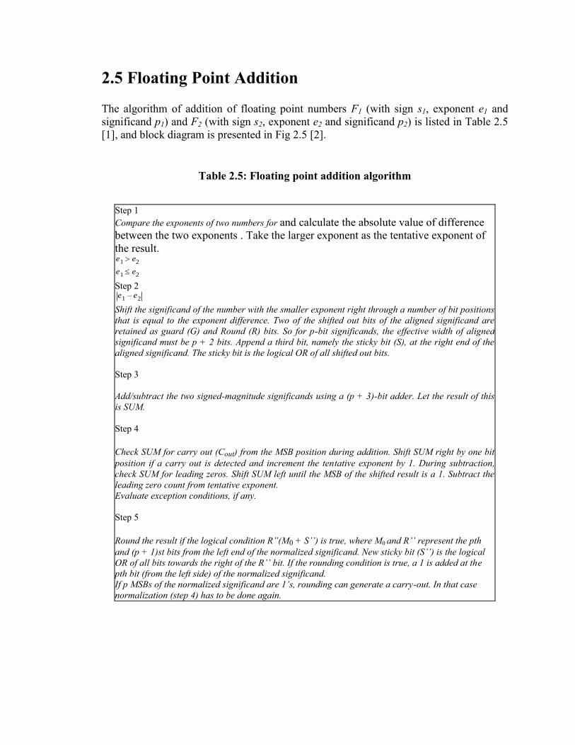
2.5 Floating Point Addition
The algorithm of addition of floating point numbers F1 (with sign s1, exponent e1 and
significand p1) and F2 (with sign s2, exponent e2 and significand p2) is listed in Table 2.5
[1], and block diagram is presented in Fig 2.5 [2].
Table 2.5: Floating point addition algorithm
Step 1
Compare the exponents of two numbers for and calculate the absolute value of difference
between the two exponents . Take the larger exponent as the tentative exponent of
the result. e1 e2
e1 e2
Step 2 e1 e2–
Shift the significand of the number with the smaller exponent right through a number of bit positions
that is equal to the exponent difference. Two of the shifted out bits of the aligned significand are
retained as guard (G) and Round (R) bits. So for p-bit significands, the effective width of aligned
significand must be p + 2 bits. Append a third bit, namely the sticky bit (S), at the right end of the
aligned significand. The sticky bit is the logical OR of all shifted out bits.
Step 3
Add/subtract the two signed-magnitude significands using a (p + 3)-bit adder. Let the result of this
is SUM.
Step 4
Check SUM for carry out (Cout) from the MSB position during addition. Shift SUM right by one bit
position if a carry out is detected and increment the tentative exponent by 1. During subtraction,
check SUM for leading zeros. Shift SUM left until the MSB of the shifted result is a 1. Subtract the
leading zero count from tentative exponent.
Evaluate exception conditions, if any.
Step 5
Round the result if the logical condition R”(M0 + S’’) is true, where M0 and R’’ represent the pth
and (p + 1)st bits from the left end of the normalized significand. New sticky bit (S’’) is the logical
OR of all bits towards the right of the R’’ bit. If the rounding condition is true, a 1 is added at the
pth bit (from the left side) of the normalized significand.
If p MSBs of the normalized significand are 1’s, rounding can generate a carry-out. In that case
normalization (step 4) has to be done again.
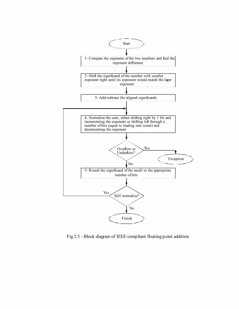
1- Compare the exponent of the two numbers and find the
2- Shift the significand of the number with smaller exponent right until its exponent would match the larger
Start
4- Normalize the sum, either shifting right by 1 bit and incrementing the exponent or shifting left through a number of bits (equal to leading zero count) and decrementing the exponent
exponent difference
exponent
Overflow orUnderflow?
5- Round the significand of the result to the appropriate
Finish
Exception
Still normalize?
3- Add/subtract the aligned significands
number of bits
Fig 2.5 - Block diagram of IEEE compliant floating point addition
Yes
No
No
Yes
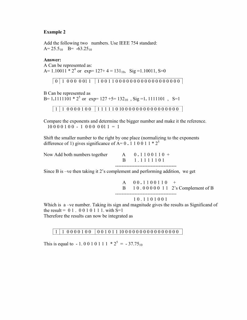
Example 2
Add the following two numbers. Use IEEE 754 standard:
A= 25.510 B= -63.2510
Answer:
A Can be represented as:
A= 1.10011 * 24
or exp= 127+ 4 = 13110, Sig =1.10011, S=0
B Can be represented as
B= 1.1111101 * 25
or exp= 127 +5= 13210 , Sig =1. 1111101 , S=1
Compare the exponents and determine the bigger number and make it the reference.
10 0 0 0 1 0 0 - 1 0 0 0 0 01 1 = 1
Shift the smaller number to the right by one place (normalizing to the exponents
difference of 1) gives significance of A= 0 . 1 1 0 0 1 1 * 25
Now Add both numbers together A 0 . 1 1 0 0 1 1 0 +
B 1 . 1 1 1 1 1 0 1
--------------------------------------
Since B is –ve then taking it 2’s complement and performing addition, we get
A 0 0 . 1 1 0 0 1 1 0 +
B 1 0 . 0 0 0 0 0 1 1 2’s Complement of B
--------------------------------------
1 0 . 1 1 0 1 0 0 1
Which is a –ve number. Taking its sign and magnitude gives the results as Significand of
the result = 0 1 . 0 0 1 0 1 1 1. with S=1
Therefore the results can now be integrated as
This is equal to - 1. 0 0 1 0 1 1 1 * 25
= - 37.7510
0 1 0 0 0 0 01 1 1 0 0 1 1 0 0 0 0 0 0 0 0 0 0 0 0 0 0 0 0 0 0
1 1 0 0 0 0 1 0 0 1 1 1 1 1 0 10 0 0 0 0 0 0 0 0 0 0 0 0 0 0 0
1 1 0 0 0 0 1 0 0 0 0 1 0 1 1 10 0 0 0 0 0 0 0 0 0 0 0 0 0 0 0

Floating Point Adder Architecture
A block diagram of floating Point adder is shown below. Exponents, sign bits and the
significands are fed into the adder. The exponents subtractor gives the amount of shift,
while the comparator gives which operands is to be shifted. The right shift of the smaller
number is achieved by a barrel shifter. Inversion of one operand is achieved by the sign
bits and the bit inverters. The Adder adds the operands and passes the results to the
rounding logic. Leading Zero Anticipator logic determines the normalization needed
where the results are normalized and the exponents are adjusted. Finally the right
significand is selected and is passed to the output together with the exponents and the
sign. This architecture features two additional non standard blocks The LZA logic and the
lines where pipelining registers can be inserted to speed up the design
Control
exponent0 1 0 1 0 1
compare right shifter
bit inverter bit inverter
LZA logic
LZA counter
56b adder
exponentsubtract
left shift incrementer
rounding control
selector
compensationshifter
exponentincrementer
difference
sign control
e1 e2 s1 s2
exponents significands
sign
1
sign
2
sig
n
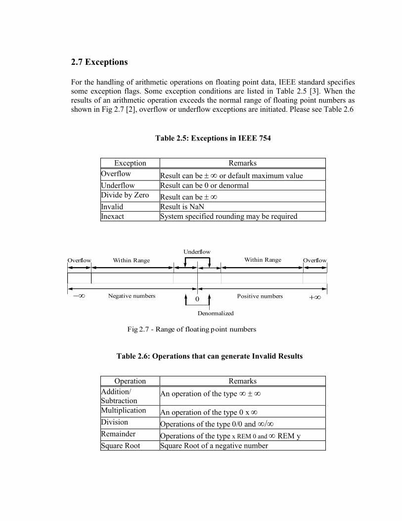
2.7 Exceptions
For the handling of arithmetic operations on floating point data, IEEE standard specifies
some exception flags. Some exception conditions are listed in Table 2.5 [3]. When the
results of an arithmetic operation exceeds the normal range of floating point numbers as
shown in Fig 2.7 [2], overflow or underflow exceptions are initiated. Please see Table 2.6
Table 2.5: Exceptions in IEEE 754
Exception Remarks
Overflow Result can be or default maximum value
Underflow Result can be 0 or denormal
Divide by Zero Result can be Invalid Result is NaN
Inexact System specified rounding may be required
Table 2.6: Operations that can generate Invalid Results
Operation Remarks
Addition/
Subtraction An operation of the type
Multiplication An operation of the type x Division Operations of the type andRemainder Operations of the type x REM 0 and REM y
Square Root Square Root of a negative number
0 Positive numbersNegative numbers
Underflow
Within RangeWithin RangeOverflow Overflow
Fig 2.7 - Range of floating point numbers
Denormalized

Detection of overflow or underflow is quite straight forward as the range of floating point
numbers is associated with the value of exponents. Table 2.6 [1] lists all possible
operations that result in an invalid exception. During invalid exception the result is set to
a NaN (not a number). Inexact exceptions are true whenever the result of a floating point
operation is not exact and IEEE rounding is required [1]. In IEEE single precision data
format, width of exponent field is 8, so 256 combinations of exponent are possible.
Among them two are reserved for special values. The value e = 0 is reserved to represent
zero (with fraction f = 0) and denormalized numbers (with fraction ). The value e = 255 is
reserved for (with fraction f = 0) and NaN (with fraction ). The leading bit of
significands (hidden bit) is zero instead of one for all the special quantities.
R S
a0
b0
p - 1 higher order bits
p - 1 higher order bits
p bit significand field
Fig. 1 - Aligned significands
G
00 0
R’ S’G’Cout
Result of significand addition before normalization shift
Aligned
significands}
R” S”M0
p - 1 higher order bits
Normalized Significand before Rounding
Significands before addition
Fig 2.6 - Significand addition, normalization and rounding
f 0
f 0
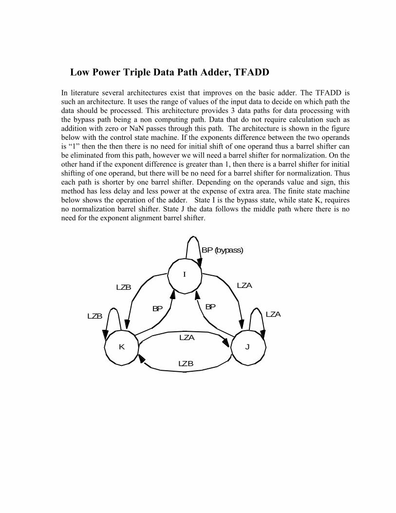
Low Power Triple Data Path Adder, TFADD
In literature several architectures exist that improves on the basic adder. The TFADD is
such an architecture. It uses the range of values of the input data to decide on which path the
data should be processed. This architecture provides 3 data paths for data processing with
the bypass path being a non computing path. Data that do not require calculation such as
addition with zero or NaN passes through this path. The architecture is shown in the figure
below with the control state machine. If the exponents difference between the two operands
is “1” then the then there is no need for initial shift of one operand thus a barrel shifter can
be eliminated from this path, however we will need a barrel shifter for normalization. On the
other hand if the exponent difference is greater than 1, then there is a barrel shifter for initial
shifting of one operand, but there will be no need for a barrel shifter for normalization. Thus
each path is shorter by one barrel shifter. Depending on the operands value and sign, this
method has less delay and less power at the expense of extra area. The finite state machine
below shows the operation of the adder. State I is the bypass state, while state K, requires
no normalization barrel shifter. State J the data follows the middle path where there is no
need for the exponent alignment barrel shifter.
BP (bypass)
BP
LZB LZA
LZB LZA
LZA
LZB
I
JK
BP

Fig 4.2 - Block diagram of the TDPFADD
(0/1 Bit Right Shifter)
Adder/Rounding Logic
Leading Zero
Counting logic
Normalization
Result Selector
Data Selector/Pre-align
Exponent Subtractor
(Left Barrel Shifter)
Data Selector
(Right Barrel Shifter)/Complementer
Pre-alignment
Input Floating Point NumbersExponents
Control LogicExponent Logic
Bypass Logic
Result Integration/Flag Logic
Flags IEEE Sum
Adder/Rounding Logic
(1 bit Right/Left Normalization
Shifter)
Exponent Incr/Decr
Result Selector

This figure shows pipelining the TPFADD to speed up its operation
Control Logic Exponent Logic
Result Integration / Flag Logic
Exponents
IEEE Sum
Input Floating Point Numbers
Bypass Logic
(0/1 Bit Right Shifter)
Adder/Rounding Logic
Leading Zero
Counter
Normalization
Result Selector
Data Selector/Pre-align
Exponent Subtractor
(Barrel Shifter Left)
Data Selector
(Barrel Shifter Right)/
(1 bit Right/Left
Complementer
Pre-alignment
Normalization
Shifter)
Exponent Incr/Decr
Result
Selector
Flag
1st
2nd
3rd
4th
5th
Critical Path
Adder/Rounding Logic

TEST RESULTS [21]
Several tests on data has been carried out. In particular IEEE standard 754 for the single
and double precision have been tested for a variety of inputs to see its performance in
extreme conditions. The code out of the generator has also been synthesized by Synopsys
using Xilinx 4052XL-1 FPGA technology. The results are shown in Table below.
Table Comparison of Synthesis results for IEEE 754 Single Precision FP addition. Using
Xilinx 4052XL-1 FPGA
PARAMETERS SIMPLE TDPFAD
D
PIPE/
TDPFADD
Maximum delay, D
(ns)
327.6 213.8 101.11
Average Power, P
(mW)@ 2.38 MHz
1836 1024 382.4
Area A, Total
number of CLBs (#)
664 1035 1324
Power Delay Product
(ns. 10mW)
7.7. *104 4.31 *10
4. 3.82 *10
4
Area Delay Product
(10 # .ns)
2.18`*104 2.21 * 10
4 1.34 *10
4
Area-Delay2 Product
(10# . ns2 )
7.13.*106 4.73 * 10
6 1.35 *10
6

Barrel Shifters In many applications such as floating point adders or multipliers circuits are needed that
can shift several data items in one move, such a circuit is named barrel shifter. A variety
of barrel shifters exist each targeted towards a special application. We will not cover all

applications rather the principal operation. The figure below shows a right shift barrel
shifter constructed from four 4-1 multiplexer that performs 0, 1, 2 ,3 bits right shift of
data x3 x2 x1 x0 in response to the control input S1 S0.
00
01
10
11
00
01
10
11
00
01
10
11
00
01
10
11
0
0
0
0
0
0
X0
X1
X2
X3
S1
S0
For example if S1S0 is 11 then the output is 000x3. It is possible to change the shift order
by reconfiguring the inputs. It is also possible to make the data rotate, by appropriate
connection of input of the multiplexer. The circuit below shows a barrel shifter that
performs rotation of data input in accordance with the control table given below.

MUX
23
01
MUX
12 0
0
MUX
123 0
01
MUX
123 0
01
D0
D1D
2D
3
Y1Y
2Y
3
S0
Select Out Put Si So Y3 Y2 Y1 Y0
Operation
0 0 D3 D2 D1 D0 No Shift
0 1 D2 D1 D0 D3 Rotate Once
1 0 D1 D0 D3 D2 Rotate Twice
1 1 D0 D3 D2 D1 Rotate 3 times
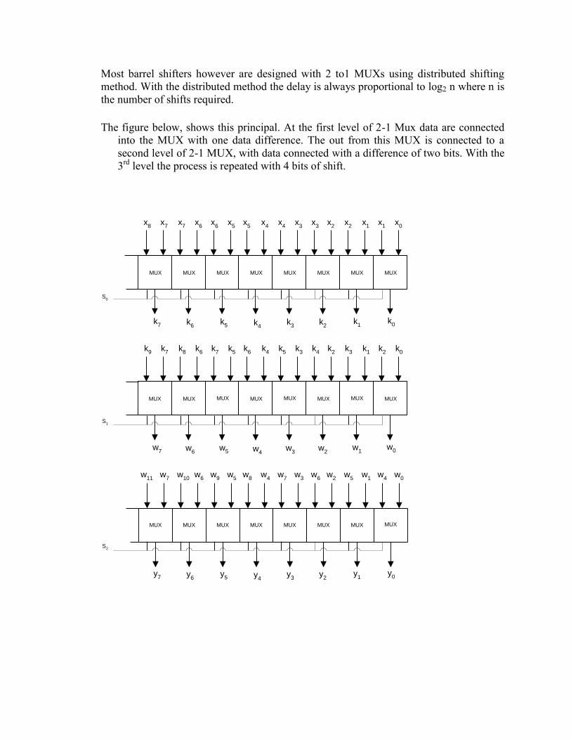
Most barrel shifters however are designed with 2 to1 MUXs using distributed shifting
method. With the distributed method the delay is always proportional to log2 n where n is
the number of shifts required.
The figure below, shows this principal. At the first level of 2-1 Mux data are connected
into the MUX with one data difference. The out from this MUX is connected to a
second level of 2-1 MUX, with data connected with a difference of two bits. With the
3rd
level the process is repeated with 4 bits of shift.
w1
w0w
7 w6
w5 w
3w4
w2
MUX MUX MUX MUX MUX MUX MUX MUX
S1
k0
k1
k7
k8
k7
k5
k4
k3
k2
k2
k3
k4
k5
k6
k6
k9
y1
y0y
7 y6
y5 y
3y4
y2
MUX MUX MUX MUX MUX MUX MUX MUX
S2
w0
w1
w7
w10
w9
w5
w6
w5
w4
w2
w3
w4
w7
w8
w6
w11
k1
k0k
7 k6
k5 k
3k4
k2
MUXMUXMUX MUXMUXMUX MUX MUX
S0
x0
x1
x7
x7
x6
x5
x3
x2
x1
x2
x3
x4
x4
x5
x6
x8

The diagram below shows setting S2=1, S1=0, S0=1, which gives us 5 shifts of data to
the right. The path of the first data bit output is shown.
w1
w0w
7 w6
w5 w
3w4
w2
MUX MUX MUX MUX MUX MUX MUX MUX
S1
k0
k1
k7
k8
k7
k5
k4
k3
k2
k2
k3
k4
k5
k6
k6
k9
y1
y0y
7 y6
y5 y
3y4
y2
MUX MUX MUX MUX MUX MUX MUX MUX
S2
w0
w1
w7
w10
w9
w5
w6
w5
w4
w2
w3
w4
w7
w8
w6
w11
k1
k0k
7 k6
k5 k
3k4
k2
MUXMUXMUX MUXMUXMUX MUX MUX
S0
x0
x1
x7
x7
x6
x5
x3
x2
x1
x2
x3
x4
x4
x5
x6
x8
S0=1 S1=0 S2=1

References
[1] R. V. K. Pillai, "On low power floating point data path architectures", Ph. D thesis,
Concordia University, Oct. 1999.
[2] David Goldberg, "Computer Arithmetic", in Computer Architecture: A quantitative
approach, D. A. Patterson and J. L. Hennessy, Morgan Kaufman, San Mateo, CA,
Appendix A, 1990.
[3] David Goldberg, "What every computer scientist should know about floating-point
arithmetic", ACM Computing Surveys, Vol. 23, No. 1, pp. 5-48, March 1991.
[4] Israel Koren, "Compuer Arithmetic Algorithms", Prentice Hall, Englewood Cliffs,
1993.
[5] S.Y. Shah, (M.A.Sc. 2000) Thesis Title: " Low Power Floating Point Architectures
for DSP."
[6] Andrew D. Booth, “A signed binary Multiplication Technique”, Quarterly J.
Mechan. Appl. Math., 4: 236-240,1951.
[7] S. Shah, A. J. Al-Khalili, D. Al-Khalili, “Comparison of 32-bit Multipliers for
Various Performance Measures,” in proceedings of ICM 2000, Nov.2000.
[8] J. Mori, M. Nagamatsu, M. Hirano, S. Tanaka, M. Noda, Y. Toyoshima, K.
Hashim-oto, H. Hayashida, and K. Maeguchi, “A 10-ns 54*54-b parallel Structured
Full array Multiplier with 0.5 micron CMOS Technology”, IEEE Journal of Solid
State Circuits, vol.26, No.4, pp.600-606, April 1991.
[9] Paul J. Song Giovanni De Micheli, “ Circuit and Architecture Trade-offs for High-
Speed Multiplication,” IEEE Journal of Solid State Circuits, vol 26, No. 9, pp.1184-
1198, Sep. 1991.
[10] R. V. K. Pillai, D. Al-Khalili and A. J. Al-Khalili,” Low Power Architecture for
Floating Point MAC Fusion,” in proceeding of IEE, Computers and Digital
Techniques.
[11] R. V. K. Pillai, D. Al-Khalili and A. J. Al-Khalili,” An IEEE Compliant Floating
Point MAF,” in proc. Of VLSI’99, Portugal, Dec.99, pp.165-168, System on Chip,
edited by L.M.Silveria, S. Devadas and R. Reis, Kluwer Academic Publishers.
[12] C.S. Wallace, “A suggestion for a Fast Multiplier”, IEEE Trans. Electronic
Computers, vol.13, pp. 14-17, Feb 1964.
[13] L.Dadda, “ Some schemes for Parallel Multipliers”, Alta Freq., 34: 349-356, 1965.
[14] L.Dadda, “On Parallel Digital Multipliers”, Alta Freq., 45:574-580,1976.
[15] Weinberger A., “4:2 Carry Save Adder Module”, IBM Tech. Disclosure Bulletin,
23,1981.
[15] O.L.MacSorley, High speed arithmetic in binary computers”, Proc.IRE, Vol. 49, pp
67-91,1961.
[17] D. Villeger and V.G Oklobdzija, “Evaluation of Booth encoding techniques for
parallel multiplier implementation”, Electronics Letters, Vol. 29, No. 23, pp.2016-
2017, 11th
November 1993.
[18] R. V. K. Pillai, D. Al-Khalili and A. J. Al-Khalili, “Energy Delay Analysis of
Partial Product Reduction Methods for Parallel Multiplier Implementation”, Digest
Of Technical Papers- 1996 International Symposium on Low Power Electronics and
Design.
[19] Hiroaki Suzuki, Hiroyuki Morinaka, Hiroshi Makino, Yasunobu Nakase, Koichiro
Mashiko and Tadashi Sumi, “Leading –Zero Anticipatory Logic for High-Speed
Floating Point Addition”, IEEE Jounal of Solid State Circuits, Vol.31, No.8 pp
1157-1164, August 1996.
[20] Shehzad Ahmad, “CAD Tool Generating the Scalable & Synthesizable Floating
Point Multiplier,” M. Eng. Project. Dept. of Electrical and Computer Engineering,
Concordia University, Jan. 2004.
[21] Masood Shah, “A CAD Tool for Generating Scalable & Synthesizable Floating
Point Adders,” M. Eng. Project, Dept. of Electrical and Computer Engineering.
Concordia University, Jan. 2004.
Appendix [20]
Introduction to IEEE-754 standard
In the early days of computers, vendors start developing their own representations and
methods of calculations. These different approaches lead to different results in
calculations. So the IEEE organization defined in the IEEE-754 standard a representation
of the floating point numbers and the operations.
Representation

As in all floating point representations, the IEEE representation divides the number of
bits into three groups, the sign, the exponent and the fractional part.
Fractional part
Fractional part is represented as sign-magnitude, which needs a reserved bit for the sign.
The exponent
The exponent is based on the biased representation. This means if k is the value of the
exponent bits, then the exponent of the floating-point number is k the bias. So to
represent the exponent zero the bits should hold the value of the bias.
A.1 Hidden-bit
Another feature of the IEEE representation is the hidden bit. This bit is the only bit to
the left of the fraction point. This bit is assumed to be 1, which gives an extra bit of
storage in the representation to increases the precision.
Sign Bit
The sign bit is as simple as it gets. 0 denotes a positive number; 1 denotes a negative
number. Flipping the value of this bit flips the sign of the number.
A.2 Precision
The IEEE-754 defines set of precisions which depends on the number of bits used. There
are two main precisions, the single and the double.
A.2.1 Single Precision
The IEEE single precision floating point standard representation require a 32 bit word,
which may be represented as numbered from 0 to 31, right to left as shown
MSB(31) 30 23 22 LSB(0)
S EEEEEEEE FFFFFFFFFFFFFFFFFFFFFFF
A.2.2 Double Precision
The IEEE single precision floating point standard representation require a 32 bit word,
which may be represented as numbered from 0 to 63, right to left as shown
MSB(63) 62 52 51 LSB(0)
S EEEEEEEEEEE FFFFFFFFFFFFFFFFFFFFFFFFFFFFFFFFFFFFFFFFFFFFFFFFFFFF

Table A.1: Exponent range and number of bits in single
and double precision floating-point representation.
A.3 Normalization
Normalization is the act of shifting the fractional part in order to make the left bit of the
fractional point “1”. During this shift the exponent is incremented.
A.3.1 Normalized numbers
Normalized numbers are numbers that have their MSB a “1” in the most left bit of the
fractional part.
A.3.2 Denormalized numbers
Denormslized numbers are the opposite of the normalized numbers. (i.e. the MSB 1 is not
in the most left bit of the fractional part).
Operations:
Some operations require that the exponent field be the same for all operands (like
addition). In this case one of the operands should be denormalized.
A.3.3 Gradual underflow:
One of the advantages of the denormalized numbers is the gradual underflow. This came
from the fact the normalized number that can represent minimum number is 1.0×2min
and
all numbers smaller than that are rounded to zero (which means there are no numbers
between 1.0×2min
and 0. The denormalized numbers expands the range and gives gradual
underflow through the division of the range between 1.0×2min
to 0 with the same steps as
the normalized numbers.
Single Double
Exponent(max) +127 +1023
Exponent(min) -126 -1022
Exponent Bias +127 +1023
Precision (#bits) 24 53
Total Bits 32 64
Sign bits 1 1
Exp Bits 8 11
Fraction 23 52

A.4 Special values
The IEEE-754 standard supports some special values that gives special functions and
give some signals.
Table A.2: Special values
Name Exponent Fraction sign Exp Bits Fract Bits
+0 min1 = 0 + All zeros All Zeros
0 min1 = 0 All zeros All Zeros
Number min e max any any Any Any
+ max+1 = 0 + All ones All zeros
max+1 = 0 All ones All zeros
NaN Max+1 0 any All ones Any
A.4.1 Zero
The zero is represented as a signed zero (-0 and +0)
-1 in the exponent and zero in the fraction.
The signed zero is important for operations that preserve the sign like multiplication and
division. It is also important to generate + or -.
A.4.2 NaN
Some computations generate undefined results like 0/0 and √[(-1)]. These operations
should be handled or we will get strange results and behavior. NaN is defined to be
generated upon these operations and so the operations are defined for it to let the
computations continue.
Whenever a NaN participates in any operation the result is NaN.
There is a family of NaN according to the above table and so the Implementations are
free to put any information in the fraction part.
All comparison operators ( = , < , ≤ , > , ≥ ) (except ( ≠ )should return false when NaN is
one of its operands.
Table A.3: Sources of NaN
Operation Produced by
+ +()
× 0×
/ 0/0, /

A.4.3 Infinity
The infinity is like the NaN, it is a way to continue the computation when some
operations are occurred.
Generation:
Infinity is generated upon operations like x/0 where x ≠ 0
Results:
The results of operations that get ∞ as a parameter is defined as: "Replace the ∞ by the
limit limx
∞ . For example 3/∞ = 0 because limx→∞3/x = 0 and √{∞} = ∞ and 4-∞ =-∞
A.5 Exceptions
Exceptions are important factors in the standard to signal the system about some
operations and results.
When an exception occurs, the following action should be taken:
A status flag is set.
The implementation should provide the users with a way to read and write the
status flags.
The Flags are ``sticky'' which means once a flag is set it remains until its
explicitly cleared.
The implementation should give the ability to install trap handlers that can be
called upon exceptions.
Common exceptions in floating-point numbers are:
Overflow, underflow and division by zero:
As is obvious from the table below, the distinction between Overflow and
division by zero is to give the ability to distinguish between the source of the
infinity in the result.
Invalid:
This exception is generated upon operations that generate NaN results. But
this is not a reversible relation (i.e. if the output is NaN because one of the
inputs is NaN this exception will not raise).
Inexact:

It is raised when the result is not exact because the result can not be
represented in the used precision and rounding cannot give the exact result.
Table A.4: Exceptions in IEEE 754 standard
Exception Cased by Result
Overflow Operation produce large number
Underflow Operation produce small number 0
Divide by Zero x/0
Invalid Undefined Operations NaN
Inexact Not exact results Round(x)
A.6 IEEE Rounding:
As not all real numbers can be represented precisely by floating point representation,
there is no way to guarantee absolute accuracy in floating point computations. Floating
point numbers are approximations of real numbers. Also the accuracy of results obtained
in a floating point arithemetic unit is limited, even if the intermediate results calculated
in the arithematic unit are accurate. The number of the computed digits may exceed the
total number of digits allowed by the format and extra digits have to be disposed before
the final results are stored in user-accessible register or memory.
IEEE 754 standard prescribes some rounding schemes to ensure acceptable accuracy of
floating point computations. The standard requires that numerical operations on floating
point operands produce rounded results. That’s is, exact results should be computed and
then rounded to the neareast floating point number using the “round to nearest – even”
approach. But in practice, with limited precision hardware resources, it is impossible to
compute exact results. So two guard bits (G & R) and third sticky (S) bit, are introduced
to ensure the computation of results within acceptable accuracy using minimum
overhead.
The default rounding mode specified by the IEEE 754 is round to nearest-even. In this
mode, the results are rounded to the nearest values and in case of a tie, an even value is
chosen. Table A .5 shows the operation of round to nearest – even, for different instances
of significand bit patterns. In this table X represents all higher order bits of the

normalized significand beyond the LSBs that take part in rounding while the period is
separating p MSBs of the normalized significand from round ( R ) and sticky (S) bits.
Table A.5: Round to nearest – even rounding
Significand Rounded
Result Error Significand
Rounded
Result Error
X0.00 X0. 0 X1.00 X1. 0
X0.01 X0. - 1/4 X1.01 X1. - 1/4
X0.10 X0. - 1/2 X1.10 X1. + 1 + 1/2
X0.11 X1. + 1/4 X1.11 X1. + 1 + 1/4
It can be seen from the table that the average bias (which is the average of the sum of
errors for all cases) for the round to nearest scheme is zero. Fig A.1illustrate the relative
positions of the decision making bits. Rounding to the nearest value necessitate a
conditional addition of 1/2 ulp (units in the last place). The decision for such addition can
be reached through the evaluation of the LSB (M0) of the most significand p bits of the
normalized significand, the round ( R ) bit and the sticky ( S ) bit. Rounding is done only
if R( M0 + S ) condition is true.
p - 1 higher order bits SRM0
p - bit significand field
Round bit
Sticky bit
Figure A.1: Normalized Significand before rounding

APPENDIX B
EXAMPLES OF SDDITION AND MULTIPLICATION
Let A= 24.25
B= -0.125
Then A is represented as S=0
M= 011000.01 = 1.100001 * 24
E = 127 + 4 =131 where the bias is 2 8-1
-1=127
MSB(31) 30 23 22 LSB(0)
S EEEEEEEE FFFFFFFFFFFFFFFFFFFFFFF
A= MSB(31) 30 23 22 LSB(0)
0 1000 0011 10000100000000000000000000
Then B is represented as S=1
M= 0.001 = 1.0000 * 2-3
E = 127 + (-3) =124 where the bias is 2 8-1
-1 =127
B= MSB(31) 30 23 22 LSB(0)
1 0111 1100 00000000000000000000000000
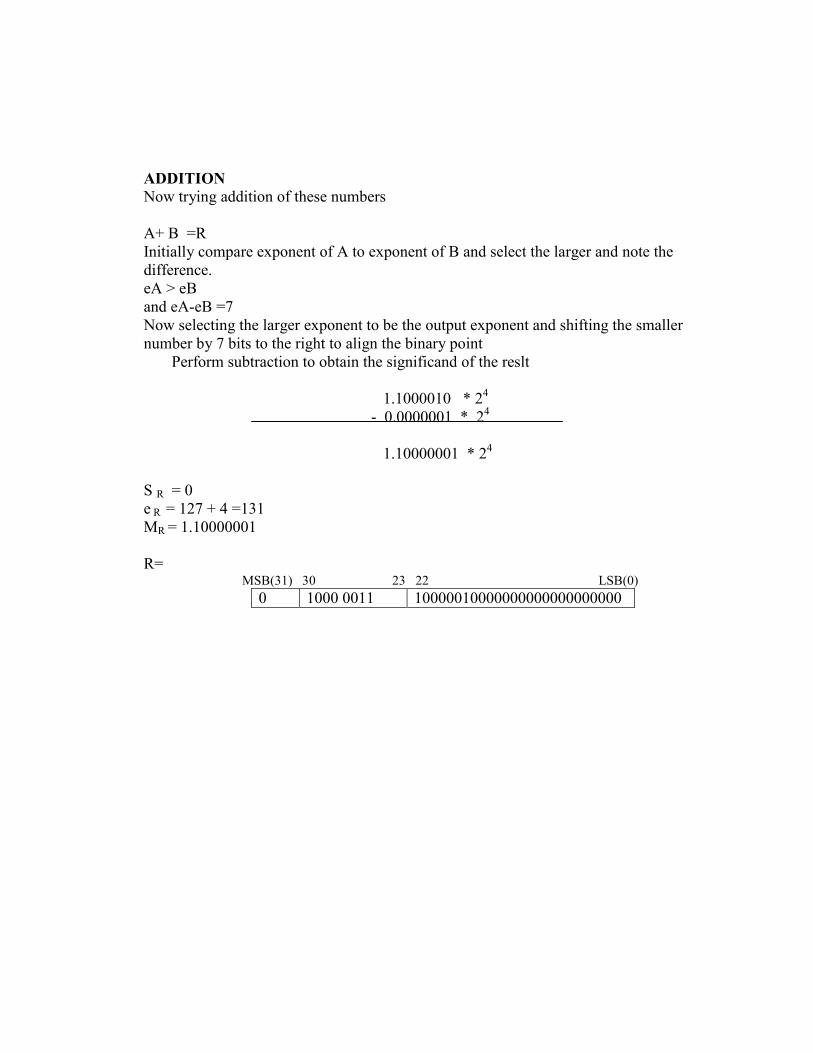
ADDITION
Now trying addition of these numbers
A+ B =R
Initially compare exponent of A to exponent of B and select the larger and note the
difference.
eA > eB
and eA-eB =7
Now selecting the larger exponent to be the output exponent and shifting the smaller
number by 7 bits to the right to align the binary point
Perform subtraction to obtain the significand of the reslt
1.1000010 * 24
- 0.0000001 * 24
1.10000001 * 24
S R = 0
e R = 127 + 4 =131
MR = 1.10000001
R= MSB(31) 30 23 22 LSB(0)
0 1000 0011 10000010000000000000000000
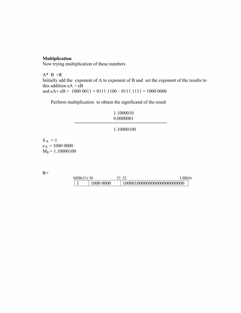
Multiplication
Now trying multiplication of these numbers
A* B =R
Initially add the exponent of A to exponent of B and set the exponent of the results to
this addition eA + eB
and eA+ eB = 1000 0011 + 0111 1100 – 0111 1111 = 1000 0000
Perform multiplication to obtain the significand of the result
1.1000010
0.0000001
1.10000100
S R = 1
e R = 1000 0000
MR = 1.10000100
R= MSB(31) 30 23 22 LSB(0)
1 1000 0000 10000100000000000000000000