floating point numbers - confex · pdf filethe decimal digits are in binary-coded decimal ......
TRANSCRIPT

Floating Point Numbers
Yes, this is the moon; our own moon. Not the final frontier but the first out post there to be exploited by our greed of consumable minerals. Soon we the human race will be there blasting the mines and depriving the orb with its riches. Do we know how much is there to steal? Pop Quiz: What is the surface area of moon?
Answer: The surface area of a sphere is: 4 * π * R2
Radius of moon is about 1738.2 KM; plugging the values: 4 * 3.14159265 * 1738.2 * 1738.2 = 37967268.598162344 KM2. That would be 37.9 million square kilometers. Two of our biggest states Texas and California are 1.7 and 0.7 million square kilometers respectively. Surface if the Moon would be about 2/3 of the area of North America or about the size of Russia, that is close to the 38 million Sq Km Now you, all mainframe assembly language tool developers i.e. old time MF programmers try doing this calculation in S/390 Assembly. Give yourself few minutes.

Address Object Code S/390 Assembly Reg./ Memory after execution 000036 00003A 000040 000044 000048 00004C 000050 000054
B375 0010 ED10 C08C 0024 7C10 C090 7C10 C094 7C10 C094 B3C9 0011 5010 C098 4E10 C09C
LZDR R1 LDE R1,FOUR MDE R1,PIE MDE R1,RADIUS MDE R1,RADIUS CGDR R1,0,R1 ST R1,FIXED CVD R1,DECIMAL
FPR1 00000000_00000000 FPR1 41400000_00000000 FPR1 41C90FDC_00000000 FPR1 445552DD_F73CD400 FPR1 47243559_FE390700 GR1 0243559F 00000003 7967263C
000088 00008C 000090 000094 000098 00009C
45B27570 41400000 413243F7 436CA333 00000000 0000000000000000
FLOAT DC FOUR DC PIE DC RADIUS DC FIXED DC DECIMAL DC
X'45B27570' E'4' E'3.14159265E+0' E'1.7382E+3' F'0' 2F'0'
This is one way of solving the problem mentioned on previous slide and, of course, we all know that there are several different ways to solve any programming problem and your way is always better than mine. This is presented here as an example. In the bottom part of the screen we have the data definitions. First at address x’88’ is a dummy definition; this is meant as an example that we can actually define everything manually as hexadecimal. Next is the “FOUR” from our formula. This is defined as Floating-point-short. (Four bytes or one word). Instead of first E, I could have used D for double word (eight bytes) or X for quad word (16 bytes). The second E is the same as normal scientific notation; it denotes the exponent of the current radix. Next two items are standard one word binary. Pie is 3.14 multiplied by 10 to power zero because we did not move the decimal point. However, Radius is 1.7 to the power three because we moved the decimal point three places to the left. Going back to the variable Four; the Floating Point value in Object column is 41400000. Bit zero of byte zero is zero signifying a positive number, for negative number it would be one. Bit 1 to 7 of byte one is 100 0001 that is x’41’ or one plus decimal 64 or one plus x’40’. We will come back to this 64 business in detail later but for the time being all the exponent values in bit 1-7 of HFP are added 64 to indicate if exponent is positive or negative. Now coming to the instruction part in top half of the screen: The instruction on address x’36’ is Load Zero to a Long register – that is a full register – bit 0 to 63. As you can see, the content of FPR1 after the execution is all zero.

LDE is Load Lengthened that is take a Short Floating Point number from storage at x’8C’ and put it in full 64 bit FP register. Content of FPR1 is the same as the storage location identified as Four. Next three instructions are to multiply a Short number from storage to a Long number in FP register. You can see that register content kept multiplying. CGDR is Convert-to-Fixed register to register. Both the register mentioned have positional meaning; a one in both places will translate FPR1 as operand two and GR1 as operand one. If it was a real life program I would have defined different equate instructions, but the point here is to give you an example and then explain, so I used same equate as operands one and operand two and Assembly still took different meanings. The content of GR1 is in Fixed Point format. Again, I could have taken care of exponent portion by adding more instructions to separate exponent and significand portions but that would have lengthened the example. Next two instructions are self explanatory; a) store R1 to Fixed (don’t know why I did it, may be yet another example ;-) b) Convert fixed to Decimal. You can see that the location identified as Decimal is 37.9 millions. Now that I got your attention without using any funny joke here is what we are going to do today:
Agenda 1. Number representation for FP arithmetic 2. Floating Point Overview 3. Floating-Point Registers 4. Floating Point Support Instructions (FPS) 5. Hexadecimal-Floating-Point Instructions (HFP) 6. Brief introduction to Binary and Decimal Floating-Point instructions
This is a complex subject and requires not only detail explanation but I do expect lots of questions and answers to help clear understanding. There are three distinct types of Floating Point Instructions HFP, BFP, and DFP instructions. Today I will only talk about Support instructions and HFP instructions and give a brief intro on the other two. For those who are interested in going further, please contact John Ehrman of IBM to schedule one more presentation in next SHARE. Disclaimer: Not all, but most of this information came from manual “z/Architecture - Principles of Operation” part number SA22-7832-07 for which IBM has the copyright.

Before we get too much confused about the calculation, let us see how different data looks like. We know that in Assembly there are four basic data format in mainframe environment.
1. Signed Binary 2. Unsigned Binary 3. Unstructured Logical data 4. Decimal data
For arithmetic operations, the decimal data is further divided as: Zoned Decimal format: Z N Z N //// Z N Z/S N
Packed decimal format: D D D D //// D D D S
These formats are very good for commercial - let us say - banking type of applications: Account balance: 12345.91 Interest rate: 5% Interest to be paid: 617.2955 We know that for amount figures, there are only two digits after decimal point. So we will treat this number as $617.30 4 * 3.14159265 * 1738.2 * 1738.2 = 37967268.598162344 KM2. However, our moon calculation is not that straight forward. The decimal point is floating all over, hence, a floating-point-decimal number. To help computers do the calculations on a fixed placement of decimal point the above calculation can be rewritten in scientific notation (SI) as: 4.000 * 3.1416 * 1.7382 * 103 * 1.7382 * 103 = 3.79 X 10⁷
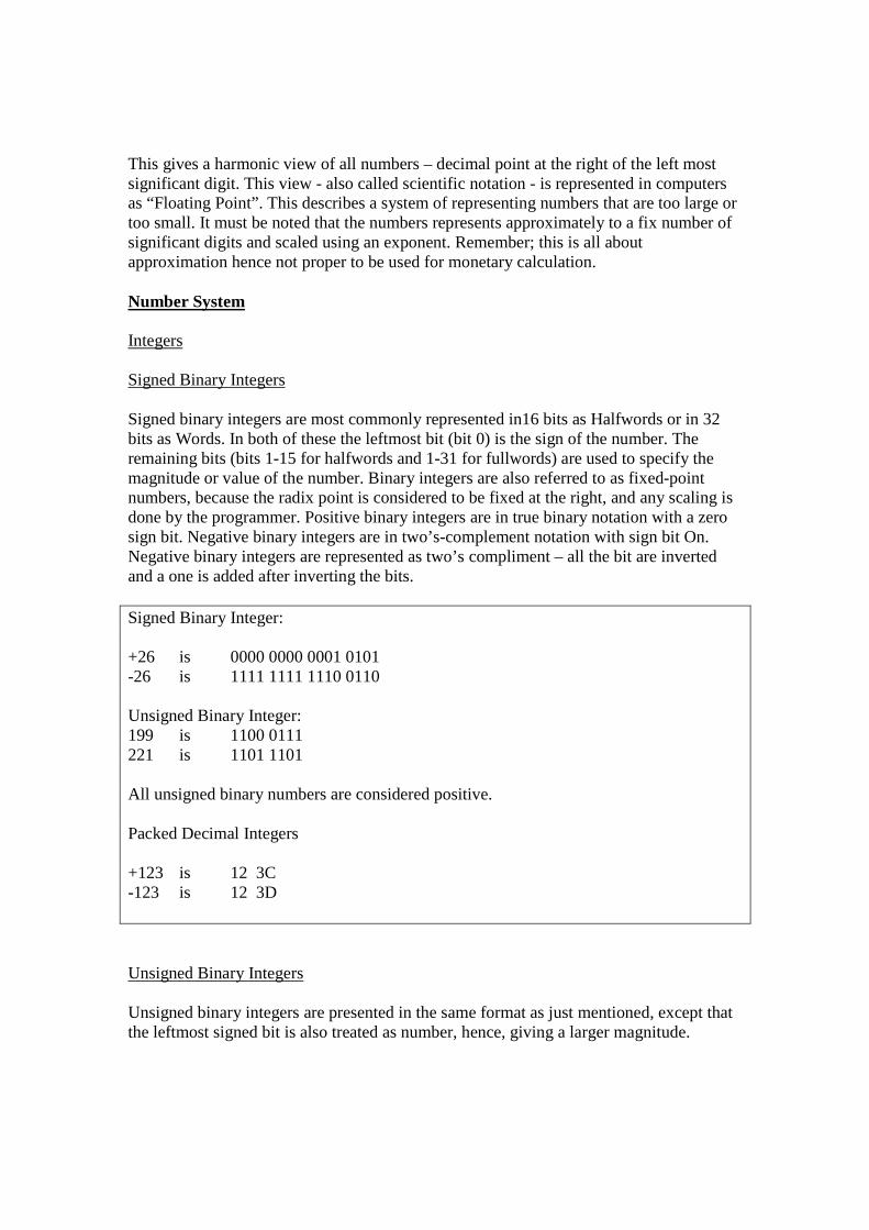
This gives a harmonic view of all numbers – decimal point at the right of the left most significant digit. This view - also called scientific notation - is represented in computers as “Floating Point”. This describes a system of representing numbers that are too large or too small. It must be noted that the numbers represents approximately to a fix number of significant digits and scaled using an exponent. Remember; this is all about approximation hence not proper to be used for monetary calculation. Number System Integers Signed Binary Integers Signed binary integers are most commonly represented in16 bits as Halfwords or in 32 bits as Words. In both of these the leftmost bit (bit 0) is the sign of the number. The remaining bits (bits 1-15 for halfwords and 1-31 for fullwords) are used to specify the magnitude or value of the number. Binary integers are also referred to as fixed-point numbers, because the radix point is considered to be fixed at the right, and any scaling is done by the programmer. Positive binary integers are in true binary notation with a zero sign bit. Negative binary integers are in two’s-complement notation with sign bit On. Negative binary integers are represented as two’s compliment – all the bit are inverted and a one is added after inverting the bits. Signed Binary Integer: +26 is 0000 0000 0001 0101 -26 is 1111 1111 1110 0110 Unsigned Binary Integer: 199 is 1100 0111 221 is 1101 1101 All unsigned binary numbers are considered positive. Packed Decimal Integers +123 is 12 3C -123 is 12 3D Unsigned Binary Integers Unsigned binary integers are presented in the same format as just mentioned, except that the leftmost signed bit is also treated as number, hence, giving a larger magnitude.

Packed Decimal Integers Decimal integers are represented by a 4-bit code. The decimal digits are in binary-coded decimal (BCD) format, with the values 0-9 encoded as 0000-1001. The sign is usually represented xC for plus and xD for minus. These are the preferred sign codes, but there are also several alternate sign codes (xA, xE, and xF for plus; xB for minus). Decimal integers may have different lengths, from one byte to one word or a multiple of words lengths. There are different decimal formats but two most popular are: Signed-Packed and Zoned. In the signed-packed-decimal format, each byte contains two decimal digits, except for the rightmost byte, which contains the sign code in the right half. In the zoned format, each byte consists of a decimal digit on the right and the zone code xF on the left, except for the rightmost byte where the sign code replaces the zone code. Floating Point Numbers
1. Hexadecimal Floating-Point Numbers (HFP) 2. Binary Floating-Point Numbers (BFP) 3. Decimal Floating-Point Numbers (DFP)
Floating-point operands have formats based on three radixes: 2, 10, or 16. These radix values lead to the terminology “binary,” “decimal,” and “hexadecimal” floating point (BFP, DFP, and HFP), respectively. The formats are also based on three operand lengths: short (32 bits), long (64 bits), and extended (128 bits). Short operands require less storage than long or extended operands. On the other hand, long and extended operands permit greater precision in computation. A finite floating-point number has three components: a sign bit, an exponent, and a significand. The magnitude (an unsigned value) of the number is the product of the significand and the radix raise to the power of the exponent. The number is positive or negative depending on whether the sign bit is zero or one, respectively. The significand consists of a string of digits, where each digit is an integral value from zero to one less than the radix (2, 10, or 16). (Thus, a BFP digit is one bit, an HFP digit is four bits, and a DFP digit is a value from zero to nine.) The number of digit positions in the significand is called the precision of the floating-point number. The significand has an implied radix point, which, depending on the view, may be considered to be on the left, to the right of the leftmost digit, on the right, or elsewhere. The exponent, a signed value, is represented as an unsigned binary value by adding a bias; the result, for BFP and DFP, is called the biased exponent; for HFP, it is called the characteristic (bias 64). The value of the bias depends on the view. In the fraction view, the radix point is considered to be the left of the significand. In the left-units view, the radix point is considered to be to the right of the leftmost digit. In the right-units view,

the radix point is considered to be on the right of the significand. By choosing the appropriate bias, any finite floating-point number can be considered in any of these views, or even in another view. For the first three of these views, the bias is called the fraction view bias, left-units-view bias, and right-units-view bias, respectively. Except where otherwise indicated, HFP is defined in terms of the fraction view, BFP terms of the left-units view, and DFP in terms of the right-units view. For HFP, the significand is considered to be a fraction with the implied radix point on the left. In this view, the significand is referred to as the fraction. For BFP, the significand consists of an implicit unit digit to the left of an implied radix point and an explicit fraction field to the right. For DFP, the significand is considered to be an integer with the implied radix point on the right. Hexadecimal-Floating-Point Numbers Same as decimal floating point numbers are expressed as a fraction multiplied by power of 10, Hexadecimal Floating Point (HFP) are expressed in fraction multiplied by the power of 16. The term floating point (HFP) indicates that the hexadecimal point (radix) is maintained by calculation, in this case by machine. The part of an HFP number which represents the fraction digits of the number is called the significand. A second part the number raised to the 16 is called exponent. It indicates the location of the radix point of the number. The significand and exponent together may be represented by short format (32 bits or one word), long format (64 bits double word), or extended format (128 bits quad word). Short HFP Number One Word S Characteristic 6-Digits Fraction 0 1 8 31 Long HPF Number Two Word S Characteristic 14-Digits Fraction 0 1 8 31 14-digit Fraction (Continued from above) 32 63 Extended HPF Number Four Word S Hgh Order Chst Leftmost14-Digits Fraction 0 1 8 31
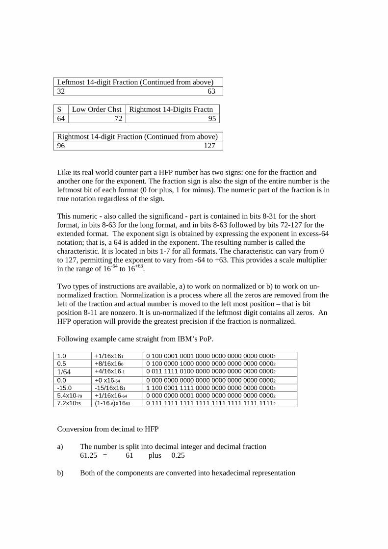
Leftmost 14-digit Fraction (Continued from above) 32 63 S Low Order Chst Rightmost 14-Digits Fractn 64 72 95 Rightmost 14-digit Fraction (Continued from above) 96 127 Like its real world counter part a HFP number has two signs: one for the fraction and another one for the exponent. The fraction sign is also the sign of the entire number is the leftmost bit of each format (0 for plus, 1 for minus). The numeric part of the fraction is in true notation regardless of the sign. This numeric - also called the significand - part is contained in bits 8-31 for the short format, in bits 8-63 for the long format, and in bits 8-63 followed by bits 72-127 for the extended format. The exponent sign is obtained by expressing the exponent in excess-64 notation; that is, a 64 is added in the exponent. The resulting number is called the characteristic. It is located in bits 1-7 for all formats. The characteristic can vary from 0 to 127, permitting the exponent to vary from -64 to +63. This provides a scale multiplier in the range of 16-64 to 16+63. Two types of instructions are available, a) to work on normalized or b) to work on un-normalized fraction. Normalization is a process where all the zeros are removed from the left of the fraction and actual number is moved to the left most position – that is bit position 8-11 are nonzero. It is un-normalized if the leftmost digit contains all zeros. An HFP operation will provide the greatest precision if the fraction is normalized. Following example came straight from IBM’s PoP. 1.0 +1/16x161 0 100 0001 0001 0000 0000 0000 0000 00002 0.5 +8/16x160 0 100 0000 1000 0000 0000 0000 0000 00002 1/64 +4/16x16-1 0 011 1111 0100 0000 0000 0000 0000 00002 0.0 +0 x16-64 0 000 0000 0000 0000 0000 0000 0000 00002 -15.0 -15/16x161 1 100 0001 1111 0000 0000 0000 0000 00002 5.4x10-79 +1/16x16-64 0 000 0000 0001 0000 0000 0000 0000 00002 7.2x1075 (1-16-6)x1663 0 111 1111 1111 1111 1111 1111 1111 11112 Conversion from decimal to HFP a) The number is split into decimal integer and decimal fraction 61.25 = 61 plus 0.25 b) Both of the components are converted into hexadecimal representation

61 = 3Cx 0.25 = 0.4x (A shortcut is to multiply by 16) c) Put them back together as hexadecimal number 3C.4x = 0.3C4x * 162 c) Characteristic is developed by adding 64 in the actual location of radix point 64 + 2 = 66 binary = 100 0010 d) Put them together with a sign bit at bit position zero. S Char Fraction 0 1000010 0110 1100 0100 0000 0000 0000 Hexadecimal-floating-point (HFP) operands have formats which provide for exponents that specify powers of the radix 16 and significands that are hexadecimal numbers. The exponent range is the same for the short, long, and extended formats. It is important to note that the results of most operations on HFP data are truncated to fit into the target format and are approximation to the actual decimal number. There are instructions available to round the result when converting to a narrower format. For HFP operands, the implicit unit digit of the significand is always zero. Please note that the value of the significand and fraction are the same. Although HFP fraction is traditionally described as significand, I will use the term fraction and the term significand interchangeably. Either normalized or un-normalized numbers may be used as operands for any HFP or DFP operation. Where, for HFP, a normalized number is one having a nonzero leftmost fraction digit, or, for DFP, a normalized number is one having a nonzero leftmost significand digit. Most HFP instructions generate normalized results for greatest precision. HFP add and subtract instructions that generate un-normalized results are also available. Binary Floating-Point (BFP) Binary-floating-point (BFP) operands have formats that provide for exponents that specify powers of the radix 2 and significands that are binary numbers. The exponent range differs for different formats, the range being greater for the longer formats. In the long and extended formats, the exponent range is significantly greater for BFP data than for HFP data. The results of operations performed on BFP data are rounded automatically to fit into the target format; the manner of rounding is determined by a program-settable BFP rounding mode. There are no un-normalized operands for BFP operations. For BFP numbers, the implicit unit digit of the significand is one. For values too small in magnitude to be represented in normalized form, the implicit unit digit is zero. These numbers are called “subnormal” numbers (these were originally called de-normalize numbers) Unlike the HFP and DFP formats, where the same value can have multiple

representations in a given format because of the possibility of un-normalized numbers, the BFP format does not allow such redundancy. Decimal Floating-Point (DFP) Decimal-floating-point (DFP) operands have formats that provide for exponents which specify powers of the radix 10 and significands that are decimal numbers. The exponent range differs for different formats, the range being greater for the longer formats. Please note that the exponent range is greater for DFP data than for BFP data. The results of operations performed on DFP data are rounded automatically to fit into the target format; the manner of rounding is determined by a program-selectable DFP rounding mode. Like HFP, DFP numbers can be normalized or un-normalized. Either normalized or un-normalized numbers may be used as operands for any DFP operation. For DFP, a normalized number is one having a nonzero leftmost significand digit. Because of the possibility of un-normalized numbers, the same value can have multiple representations in a given DFP format. The representations having the same value are called members of a cohort. Unlike HFP, DFP instructions generate normalized results for greater precision only when the result is inexact. When the result is exact, most DFP instructions produce a value in the form that preserves information called the quantum. Floating-Point Data in Storage and Registers All floating-point data formats appear in storage in the same left-to-right sequence as all other data formats. (No little-endian big-endian argument here ;-) data of the higher significance are written in the lowest numbered bytes and bits. The data that is of lower value is written in higher number bytes / address numbers. Other non-number constructs for BFP and DFP Sign Bit All floating-point data have a sign bit. The sign bit is zero for plus and one for minus. Infinities BFP and DFP data include an infinite numeric datum, called infinity. Infinities can participate in most arithmetic operations and give a consistent result, usually infinity. An infinity has a sign bit. In comparisons, infinities of the same sign compare equal, +∞ compares greater than any finite number, and -∞ compares less than any finite number. Not-A-Number (NaN) BFP and DFP data types include a nonnumeric datum, called not-a-number (or NaN). A NaN is produced in place of a numeric result after an invalid operation when there is no IEEE trap action. NaNs may also be used by the program to flag special operands, such as the contents of an uninitialized storage area. A NaN has a sign bit, a NaN-type bit, and a payload.

Normally, QNaNs are just propagated during computations so that they will remain visible at the end; Signaling and Quiet NaNs There are two types of NaNs, signaling and quiet. A signaling NaN (SNaN) is distinguished from the corresponding quiet NaN (QNaN) by the NaN-type bit. For BFP, the NaN-type bit is the leftmost bit of the fraction field, and is called the QNaN bit: a BFP NaN is an SNaN, or a QNaN, depending on whether the QNaN bit is zero, or one, respectively. For DFP, the NaN-type bit is in bit position 6 in all three formats, and is called the SNaN bit: a DFP NaN is a QNaN, or an SNaN, depending on whether the SNaN bit is zero, or one, respectively. Payload NaNs include diagnostic information called the payload. For BFP, the payload has two fewer bits than the precision and is considered to be a left-aligned bit-reversed binary integer. For DFP, the payload has one fewer digit than the precision and is considered to be a right-aligned decimal integer. For both BFP and DFP the payload of a NaN is considered to be an unsigned integer. Registers And Controls Floating-Point Registers All floating-point instructions (FPS, BFP, DFP, and HFP) use the same 16 floating-point registers. The floating-point registers are identified by the numbers 0-15 and are designated by a four-bit R field in floating-point instructions. Each floating-point register is 64 bits long and can either work on a short (32-bit) or a long (64-bit) floating-point operand or a long (64 bits) operand. A short floating-point datum requires only the leftmost 32 bit (lower numbered) positions of a floating-point register. The rightmost 32 bit positions of the register are ignored when the register is the source of an operand in the short format, and they remain unchanged when a short result is placed in the register. A datum in the Long format uses all the 64 bits. A datum in the extended (128-bit) format occupies a register pair. Register pairs are formed by coupling the 16 registers as follows: 0 and 2, 4 and 6, 8 and 10, 12 and 14, 1 and 3, 5 and 7, 9 and 11, and 13 and 15. Each of the eight pairs is referred to by the number of the lower-numbered register of the pair. To visualize consider the following: only the adjacent of the following table can be used as pair. 0 2 4 6 8 10 12 14 1 3 5 7 9 11 13 15

An instruction specifying a floating-point operand in the extended format must designate register 0, 1, 4, 5, 8, 9, 12, or 13 (again adjacent); otherwise, a specification exception is recognized. Floating-Point-Control (FPC) Register The floating-point-control (FPC) register is a 32-bit register that contains mask bits, flag bits, a data exception code, IEEE exception trap code, and two rounding-mode fields. The bits of the FPC register are often referred to as, for example, FPC 1.0, meaning bit 0 of byte 1 of the register. IEEE Invalid Operation An IEEE-invalid-operation exception is recognized when, in the execution of an IEEE computational operation, any of the following occurs:
1. An SNaN is encountered in an IEEE computational operation. 2. A QNaN is encountered in an unordered-signaling comparison (COMPARE AND
SIGNAL with a QNaN operand). 3. An IEEE difference is undefined (addition of infinities of opposite sign, or
subtraction of infinities of like sign). 4. An IEEE product is undefined (zero times infinity). 5. An IEEE quotient is undefined (DIVIDE instruction with both operands zero or
both operands infinity). 6. A BFP remainder is undefined (DIVIDE TO INTEGER with a dividend of
infinity or a divisor of zero). 7. A BFP square root is undefined (negative nonzero operand). 8. Any other IEEE computational operation whose result is either undefined or not
represent able in the target format. Control Instructions The floating-point-support instructions and their mnemonics and operation codes are listed in the following Figure. All floating-point-support instructions are subject to the AFP-register-control bit, bit 45 of control register 0. The AFP-register-control bit must be one when an AFP register is specified as an operand location; otherwise, an AFP-register data exception, DXC 1, is recognized. Mnemonics for the floating-point instructions have an R as the last letter when the instruction is in the RR, RRE, or RRF format. Certain letters are used for floating-point instructions to represent operand-format length, as follows: D Long E Short X Extended Condition Codes for IEEE Instructions

For those operations which set the condition code to indicate the value of an IEEE result, condition codes 0, 1, and 2 are set to indicate that the result is a zero of either sign, less than zero, or greater than zero, respectively. The condition-code setting depends only on an inspection of the rounded result. For comparison operations, condition codes 0, 1, and 2 indicate equal, low, or high, respectively. These settings are the same as for the HFP instructions. Condition code 3 can also be set. After an arithmetic operation, condition code 3 indicates a NaN result of either sign. After a comparison, it indicates that a NaN was involved in the comparison (the unordered condition). CONVERT BFP TO HFP Mnemonic R1,R2 [RRE] Op Code //////// R1 R2 0 16 24 28 31
Mnemonic Op Code Operands THDER 'B358' Short BFP operand, long HFP result THDR 'B359' Long BFP operand, long HFP result The second operand (the source operand) is converted from the binary-floating-point (BFP) format to the hexadecimal-floating-point (HFP) format, and the normalized result is placed at the first-operand location. The sign and magnitude of the source operand are tested to determine the setting of the condition code. For numeric operands, the sign of the result is the sign of the source operand. If the source operand has a sign bit of one and all other operand bits are zeros, the result also is a one followed by all zeros. When, for THDR, the characteristic of the result would be negative, the result is made all zeros but with the same sign as that of the source operand, and condition code 1 or 2 is set to indicate the sign of the source operand. Resulting Condition Code: 0 Source was zero 1 Source was less than zero 2 Source was greater than zero 3 Special case CONVERT HFP TO BFP Mnemonic R1,R2 [RRE] Op Code M3 ///// R1 R2 0 16 20 24 28 31

Mnemonic Op Code Operands TBEDR ‘B350' Long HFP operand, short BFP result TBDR ‘B351' Long HFP operand, long BFP result The second operand (the source operand) is converted from the hexadecimal-floating-point (HFP) format to the binary-floating-point (BFP) format, and the result rounded according to the rounding method specified by the M3 field is placed at the first-operand location. The sign and magnitude of the source operand are tested to determine the setting of the condition code. The M3 field contains a modifier specifying a rounding method, as follows: M3 Effective Rounding Method 0 Round toward 0 1 Round to nearest with ties away from 0 4 Round to nearest with ties to even 5 Round toward 0 6 Round toward +∞ 7 Round toward -∞ COPY SIGN CPSDR R1,R3, R2 [RRF]
‘B372’ R3 ///// R1 R2 0 16 20 24 28 31
The second operand is placed at the first-operand location with the sign bit set to the sign of the third operand. The first, second, and third operands are each in a 64-bit floating-point register. The sign bit of the second operand and bits 1-63 of the third operand are ignored. EXTRACT FPC EFPC R1 [RRE]
‘B38C’ ///// ///// R1 ///// 0 16 20 24 28 31
The contents of the FPC (floating-point-control) register are placed in bit positions 32-63 of the general register designated by R1. Bit positions 0-31 of the general register remain unchanged. LOAD Mnemonic R1,R2 [RR]

Op Code R1 R2 0 8 12 15
Mnemonic Op Code Operands LER '38' Short LDR '28' Long Mnemonic2 R1,R2 [RRE]
Op Code //////// R1 R2 0 16 24 28 31
Mnemonic Op Code Operands LXR 'B365' Extended Mnemonic3 R1,D2(X2,B2) [RX]
Op Code R1 X2 B1 D2 0 8 12 16 20 31
Mnemonic3 Op Code Operands LE '78' Short LD '68' Long Mnemonic4 R1,D2(X2,B2) [RXY] Op Code R1 X2 B2 DL2 DH2 Op Code 0 8 12 16 20 32 40 47
Mnemonic3 Op Code Operands LEY ‘ED64’ Short LDY ‘ED65’ Long The second operand is placed unchanged at the first operand location. The operation is performed without inspecting the contents of the second operand; no arithmetic exceptions are recognized. For LXR, the R fields must designate valid floating-point-register pairs; otherwise, a specification exception is recognized. LOAD COMPLEMENT LCDFR R1,R2 [RRE] Op Code //////// R1 R2 0 16 24 28 31

The second operand is placed at the first-operand location with the sign bit inverted. Both the first and second operands are each in a 64-bit floating-point register. LOAD FPC LFPC D2(B2) [S]
‘B29D’ B2 D2 0 16 20 31
The four-byte second operand in storage is loaded into the FPC (floating-point-control) register. Bits corresponding to unsupported bit positions in the FPC register must be zero; otherwise, a specification exception is recognized. LOAD FPC AND SIGNAL LFAS D2(B2) [S]
‘B2BD’ B 2 D2 0 16 20 31
First, bits 0-4 of byte 1 of the floating-point-control (FPC) register at the beginning of the operation are preserved to be used as signaling flags. Next, the contents of the source operand are placed in the FPC register; then the flags in the FPC register are set to the logical OR of the signaling flags and the source flags. Finally, the conditions for simulated- IEEE-exception trap action are examined. The source operand is the second operand in storage. If any signaling flag is one and the corresponding source mask is also one, simulated-IEEE-exception trap action occurs. The data-exception code (DXC) in the FPC register is updated to indicate the specific cause of the interruption and a data-exception program interruption occurs at completion of the instruction execution. If no signaling flag is enabled, the DXC in the FPC register remains as loaded from the source and instruction execution completes with no trap action. Bits in the source operand that correspond to unsupported bit positions in the FPC register must be zero; otherwise, a specification exception is recognized. LOAD FPR FROM GR LDGR R1,R2 [RRE]
‘B3C1’ //////// R1 R2 0 16 24 28 31

The second operand is placed at the first-operand location. The second operand is in a general register, and the first operand is in a floating-point register. LOAD GR FROM FPR LGGR R1,R2 [RRE]
‘B3CD’ //////// R1 R2 0 16 24 28 31
The second operand is placed at the first-operand location. The second operand is in a floating-point register, and the first operand is in a general register. LOAD NEGATIVE LGGR R1,R2 [RRE]
‘B371’ //////// R1 R2 0 16 24 28 31
The second operand is placed at the first-operand location with the sign bit set to one. Both the first and second operands are each in a 64-bit floating-point register. LOAD POSITVE LPDFR R1,R2 [RRE]
‘B370’ //////// R1 R2 0 16 24 28 31
The second operand is placed at the first-operand location with the sign bit set to zero. Both the first and second operands are each in a 64-bit floating-point register. LOAD ZERO Mnemonic R1 [RRE] Op Code //////// R1 ////// 0 16 24 28 31
Mnemonic Op Code Operands LZER ‘B374' ‘ Short LZDR ‘B375' ‘ Short LZXR ‘B376' ‘ Short All bits of the first operand are set to zeros.

For LZXR, The R1 field must designate a valid floating-point-register pair; otherwise, a specification exception is recognized. PERFORM FLOATING-POINT OPERATION PFPO [E]
‘010A’ 0 15
The operation specified by the function code in general register 0 is performed and the condition code is set to indicate the result. When there are no exceptional conditions, condition code 0 is set. When an IEEE nontrap exception is recognized, condition code 1 is set. When an IEEE trap exception with alternate action is recognized, condition code 2 is set. A 32-bit return code is placed in bits 32-63 of general register 1; bits 0-31 of general register 1 remain unchanged. The PERFORM FLOATING-POINT OPERATION (PFPO) instruction is subject to the AFP-register control bit bit 45 of control register 0. For PFPO to be executed successfully the AFP-register-control bit must be one; otherwise, an AFP-register data exception, DXC 1, is recognized. Bit 32 of general register 0 is the test bit. When bit 32 is zero, the function specified by bits 33-63 of general register 0 is performed; each field in bits 33-63 must be valid and the combination must be a valid and installed function; otherwise a specification exception is recognized. When bit 32 is one, the function specified by bits 33-63 is not performed but, instead, the condition code is set to indicate whether these bits specify a valid and installed function; the condition code is set to 0 if the function is valid and installed or to 3 if the function is invalid or not installed. This will be useful if additional functions are assigned in the future. This definition is written as if the test bit is zero except when stated otherwise. Bits 33-39 of GR0 specify the operation type. Only one operation type is currently defined: 01, hex, is PFPO Convert Floating-Point Radix. Note: See page 658 of PoP SET BFP ROUNDING MODE SRNM D2(B2) [S]
‘B299’ B2 D2 0 16 20 31
The BFP rounding-mode bits are set from the second-operand address.
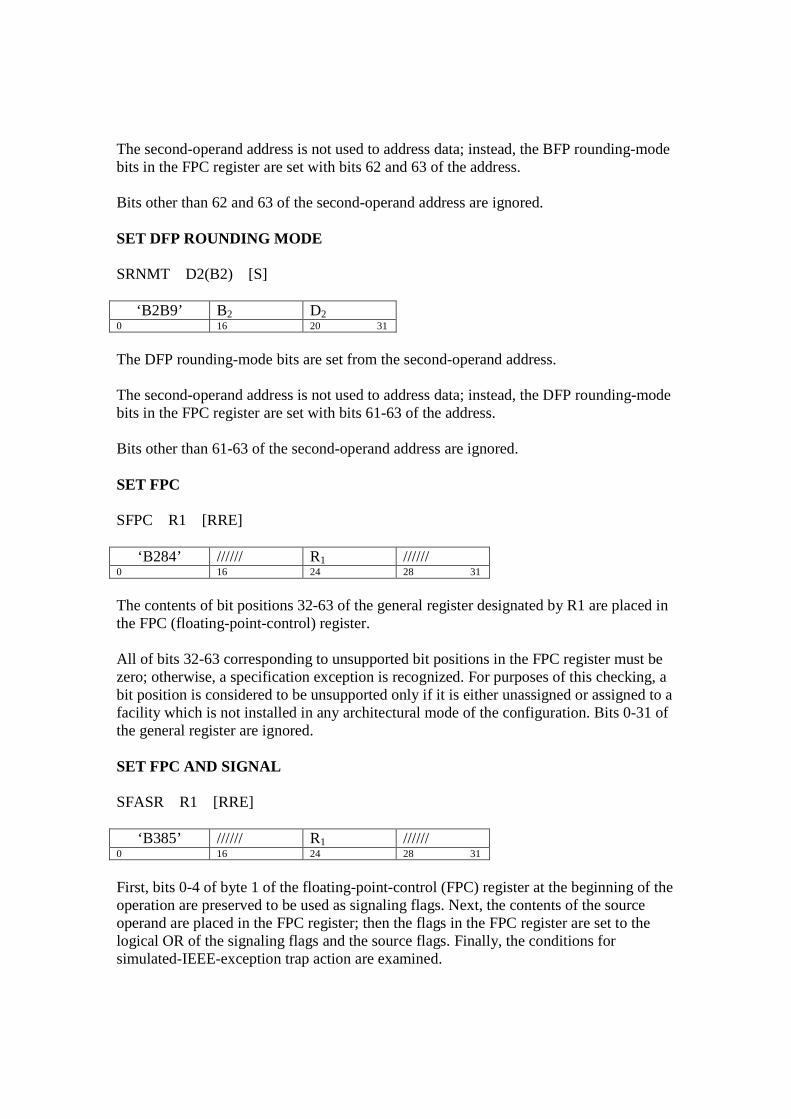
The second-operand address is not used to address data; instead, the BFP rounding-mode bits in the FPC register are set with bits 62 and 63 of the address. Bits other than 62 and 63 of the second-operand address are ignored. SET DFP ROUNDING MODE SRNMT D2(B2) [S]
‘B2B9’ B2 D2 0 16 20 31
The DFP rounding-mode bits are set from the second-operand address. The second-operand address is not used to address data; instead, the DFP rounding-mode bits in the FPC register are set with bits 61-63 of the address. Bits other than 61-63 of the second-operand address are ignored. SET FPC SFPC R1 [RRE]
‘B284’ ////// R1 ////// 0 16 24 28 31
The contents of bit positions 32-63 of the general register designated by R1 are placed in the FPC (floating-point-control) register. All of bits 32-63 corresponding to unsupported bit positions in the FPC register must be zero; otherwise, a specification exception is recognized. For purposes of this checking, a bit position is considered to be unsupported only if it is either unassigned or assigned to a facility which is not installed in any architectural mode of the configuration. Bits 0-31 of the general register are ignored. SET FPC AND SIGNAL SFASR R1 [RRE]
‘B385’ ////// R1 ////// 0 16 24 28 31
First, bits 0-4 of byte 1 of the floating-point-control (FPC) register at the beginning of the operation are preserved to be used as signaling flags. Next, the contents of the source operand are placed in the FPC register; then the flags in the FPC register are set to the logical OR of the signaling flags and the source flags. Finally, the conditions for simulated-IEEE-exception trap action are examined.

The source operand is in bits 32-63 of the general register designated by R1; bits 0-31 of the general register are ignored. STORE Mnemonic R1,D2(X2,B2) [RX]
‘Op Code R1 X2 B1 D2 0 8 12 16 20 31
Mnemonic Op Code Operands STE '70' Short STD '60' Long Mnemonic R1,D2(X2,B2) [RXY]
‘Op Code R1 X2 B2 DL2 DH2 Op Code 0 8 12 16 20 32 40 47
Mnemonic Op Code Operands STEY ‘ED66’ Short STDY ‘ED67’ Long The first operand is placed unchanged in storage at the second-operand location. The displacement for STE and STD is treated as a 12-bit unsigned binary integer. The displacement for STEY and STDY is treated as a 20-bit signed binary integer. STORE FPC STFPC D2(B2) [S]
‘B29C’ B2 D2 0 16 20 31
The contents of the FPC (floating-point-control) register are placed in storage at the second-operand location. The operand is four bytes in length. All 32 bits of the FPC register are stored. Hexadecimal-Floating-Point Instructions Normalization A quantity can be represented with the greatest precision by an HFP number of a given fraction length when that number is normalized. A normalized HFP number has a nonzero leftmost hexadecimal fraction digit. If one or more leftmost fraction digits are zeros, the number is said to be un-normalized. Un-normalized numbers are normalized by shifting the fraction left, one digit at a time, until the leftmost hexadecimal digit is

nonzero and reducing the characteristic by the number of hexadecimal digits shifted. A number with a zero fraction cannot be normalized; either its characteristic remains unchanged or its characteristic is made zero when the result is forced to be a true zero. HFP Data Formats HFP numbers have a 32-bit (short) format, a 64-bit (long) format, or a 128-bit (extended) format. Numbers in the short and long formats may be designated as operands both in storage and in the floating-point registers, whereas operands having the extended format can be designated only in the floating-point registers. In all formats, the first bit (bit 0) is the sign bit (S). The next seven bits are the characteristic. In the short and long formats, the remaining bits constitute the fraction, which consists of six or 14 hexadecimal digits, respectively. Short HFP Number One Word S Characteristic 6-Digits Fraction 0 1 8 31 Long HPF Number Two Word S Characteristic 14-Digits Fraction 0 1 8 31 14-digit Fraction (Continued from above) 32 63 Extended HPF Number Four Word S Hgh Order Chst Leftmost14-Digits Fraction 0 1 8 31 Leftmost 14-digit Fraction (Continued from above) 32 63 S Low Order Chst Rightmost 14-Digits Fractn 64 72 95 Rightmost 14-digit Fraction (Continued from above) 96 127

ADD NORMALIZED Mnemonic R1,R2 [RR]
Op Code R1 R2 0 16 20 31
Mnemonic Op Code Operands AER '3A' Short HFP ADR '2A' Long HPF AXR '36' Extended HPF Mnemonic R1,D2(X2,B2) [RX]
Op Code R1 X2 B2 D2 0 8 12 16 20 31
Mnemonic Op Code Operands AE '74' Short HFP AD '6A' Long HFP The second operand is added to the first operand, and the normalized sum is placed at the first-operand location. Addition of two HFP numbers consists in characteristic comparison, fraction alignment, and signed fraction addition. The characteristics of the two operands are compared, and the fraction accompanying the smaller characteristic is aligned with the other fraction by a right shift, with its characteristic increased by one for each hexadecimal digit of shift until the two characteristics agree. When a fraction is shifted right during alignment, the leftmost hexadecimal digit shifted out is retained as a guard digit. The fraction that is not shifted is considered to be extended with a zero in the guard-digit position. When no alignment shift occurs, both operands are considered to be extended with zeros in the guard-digit position. The fractions with signs are then added algebraically to form a signed intermediate sum. The intermediate-sum fraction consists of seven (short format), 15 (long format), or 29 (extended format) hexadecimal digits, including the guard digit, and a possible carry. If a carry is present, the sum is shifted right one digit position so that the carry becomes the leftmost digit of the fraction, and the characteristic is increased by one. If the addition produces no carry. ADD UNNORMALIZED Mnemonic R1,R2 [RR]
Op Code R1 R2

0 16 20 31
Mnemonic Op Code Operands AUR '3E' Short HFP AWR '2E' Long HPF Mnemonic R1,D2(X2,B2) [RX]
Op Code R1 X2 B2 D2 0 8 12 16 20 31
Mnemonic Op Code Operands AU '7E' Short HFP AW '6E' Long HFP The second operand is added to the first operand, and the un-normalized sum is placed at the first-operand location. COMPARE Mnemonic R1,R2 [RR]
Op Code R1 R2 0 16 20 31
Mnemonic Op Code Operands CER '39' Short HFP CDR '29' Long HPF Mnemonic R1,R2 [RRE]
Op Code ////// R1 R2 0 16 24 28 31
Mnemonic Op Code Operands CXR ‘B369’ Extended HFP Mnemonic R1,D2(X2,B2) [RX]
Op Code R1 X2 B2 D2 0 8 12 16 20 31
Mnemonic Op Code Operands CE '79' Short HFP CD '69' Long HFP
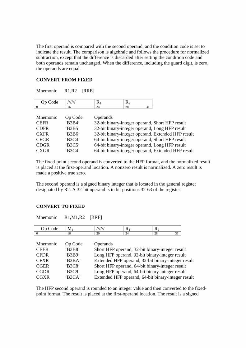
The first operand is compared with the second operand, and the condition code is set to indicate the result. The comparison is algebraic and follows the procedure for normalized subtraction, except that the difference is discarded after setting the condition code and both operands remain unchanged. When the difference, including the guard digit, is zero, the operands are equal. CONVERT FROM FIXED Mnemonic R1,R2 [RRE]
Op Code ////// R1 R2 0 16 24 28 31
Mnemonic Op Code Operands CEFR ‘B3B4’ 32-bit binary-integer operand, Short HFP result CDFR ‘B3B5’ 32-bit binary-integer operand, Long HFP result CXFR ‘B3B6’ 32-bit binary-integer operand, Extended HFP result CEGR ‘B3C4’ 64-bit binary-integer operand, Short HFP result CDGR ‘B3C5’ 64-bit binary-integer operand, Long HFP result CXGR ‘B3C4’ 64-bit binary-integer operand, Extended HFP result The fixed-point second operand is converted to the HFP format, and the normalized result is placed at the first-operand location. A nonzero result is normalized. A zero result is made a positive true zero. The second operand is a signed binary integer that is located in the general register designated by R2. A 32-bit operand is in bit positions 32-63 of the register. CONVERT TO FIXED Mnemonic R1,M1,R2 [RRF]
Op Code M1 ////// R1 R2 0 16 20 24 28 31
Mnemonic Op Code Operands CEER ‘B3B8’ Short HFP operand, 32-bit binary-integer result CFDR ‘B3B9’ Long HFP operand, 32-bit binary-integer result CFXR ‘B3BA’ Extended HFP operand, 32-bit binary-integer result CGER ‘B3C8’ Short HFP operand, 64-bit binary-integer result CGDR ‘B3C9’ Long HFP operand, 64-bit binary-integer result CGXR ‘B3CA’ Extended HFP operand, 64-bit binary-integer result The HFP second operand is rounded to an integer value and then converted to the fixed-point format. The result is placed at the first-operand location. The result is a signed

binary integer that is placed in the general register designated by R1. A 32-bit result replaces bits 32-63 of the register, and bits 0-31 of the register remain unchanged. The second operand is rounded to an integer value by rounding as specified by the modifier in the M3 field: M3 Effective Rounding Method 0 Round toward 0 1 Round to nearest with ties away from 0 4 Round to nearest with ties to even 5 Round toward 0 6 Round toward +∞ 7 Round toward -∞ DIVIDE Mnemonic R1,R2 [RR]
Op Code R1 R2 0 16 20 31
Mnemonic Op Code Operands DER '3D' Short HFP DDR '2D' Long HPF Mnemonic2 R1,R2 [RRE]
Op Code ////// R1 R2 0 16 24 28 31
Mnemonic Op Code Operands DXR ‘B22D’ Extended HFP Mnemonic3 R1,D2(X2,B2) [RX]
‘Op Code R1 X2 B2 D2 0 8 12 16 20 31
Mnemonic Op Code Operands DE '7D' Short HFP DD '6D' Long HFP The first operand (the dividend) is divided by the second operand (the divisor), and the normalized quotient is placed at the first-operand location. No remainder is preserved. HFP division consists in characteristic subtraction and fraction division. The operands are first normalized to eliminate leading hexadecimal zeros. The difference between the

dividend and divisor characteristics of the normalized operands, plus 64, is used as the characteristic of an intermediate quotient. HALVE Mnemonic R1,R2 [RR]
Op Code R1 R2 0 16 20 31
Mnemonic Op Code Operands HER '34' Short HFP HDR '24' Long HPF The second operand is divided by 2, and the normalized quotient is placed at the first-operand location. LOAD AND TEST Mnemonic R1,R2 [RR]
Op Code R1 R2 0 16 20 31
Mnemonic Op Code Operands LTER '32' Short HFP LTDR '22' Long HPF Mnemonic2 R1,R2 [RRE]
Op Code ////// R1 R2 0 16 24 28 31
Mnemonic Op Code Operands LTXR 'B362' Extended HFP The second operand is placed at the first-operand location, and its sign and magnitude are tested to determine the setting of the condition code. The condition code is set the same as for a comparison of the second operand with zero. LOAD COMPLEMENT Mnemonic R1,R2 [RR]
Op Code R1 R2 0 16 20 31

Mnemonic Op Code Operands LCER '33' Short HFP LCDR '23' Long HPF Mnemonic2 R1,R2 [RRE]
Op Code ////// R1 R2 0 16 24 28 31
Mnemonic Op Code Operands LCXR 'B363' Extended HFP The second operand is placed at the first-operand location with the sign bit inverted. The sign bit is inverted even if the operand is zero. For all operand lengths, the source fraction is placed unchanged in the result. LOAD FP INTEGER Mnemonic R1,R2 [RRE]
Op Code ////// R1 R2 0 16 24 28 31
Mnemonic Op Code Operands LIER 'B377' Short HFP LIDR 'B37F' Long HFP LIXR 'B367' Extended HFP The second operand is truncated (rounded toward zero) to an integer value in the same floating-point format and the normalized result is placed at the first-operand location. A nonzero result is normalized. A zero result is made a positive true zero. LOAD LENGTHENED Mnemonic R1,R2 [RRE]
Op Code ////// R1 R2 0 16 24 28 31
Mnemonic Op Code Operands LDER 'B324' Short HFP operand 2, Long HFP operand 1 LXDR 'B325' Long HFP operand 2, extended HFP operand 1 LXER 'B326' Short HFP operand 2, Extended HFP operand 1 Mnemonic R1,D2(X2,b2) [RXE]
Op Code R1 X2 B2 D2 ////// Op Code

0 8 12 16 20 22 40 47
Mnemonic Op Code Operands LDE 'ED24' Short HFP operand 2, Long HFP operand 1 LXD 'ED25' Long HFP operand 2, extended HFP operand 1 LXE 'ED26' Short HFP operand 2, Extended HFP operand 1 The second operand is extended to a longer format, and the result is placed at the first-operand location. LOAD NIGATIVE Mnemonic R1,R2 [RR]
Op Code R1 R2 0 16 20 31
Mnemonic Op Code Operands LNER '31' Short HFP LDDR '21' Long HPF Mnemonic2 R1,R2 [RRE]
Op Code ////// R1 R2 0 16 24 28 31
Mnemonic Op Code Operands LNXR 'B361' Extended HFP The second operand is placed at the first-operand location with the sign bit made one. LOAD POSITIVE Mnemonic R1,R2 [RR]
Op Code R1 R2 0 8 12 15
Mnemonic Op Code Operands LPER '30' Short HFP LPDR '20' Long HPF Mnemonic2 R1,R2 [RRE]
Op Code ////// R1 R2 0 16 24 28 31
Mnemonic Op Code Operands

LPXR 'B360' Extended HFP The second operand is placed at the first-operand location with the sign bit made zero. LOAD ROUNDED Mnemonic R1,R2 [RR]
Op Code R1 R2 0 8 12 15
Mnemonic Op Code Operands LEDR '35' Long HFP operand 2, Short HFP operand 1 LDXR '25' Extended Long HPF operand 2, Long operand 1 Mnemonic2 R1,R2 [RRE]
Op Code ////// R1 R2 0 16 24 28 31
Mnemonic Op Code Operands LEXR 'B366' Extended HFP 2, short HFP operand 1 The second operand is placed at the first-operand location with the sign bit made zero. MULTIPLY Mnemonic R1,R2 [RR]
Op Code R1 R2 0 8 12 15
Mnemonic Op Code Operands MDR '2C' Long HFP MXR '26' Short HFP multiplier, Long HFP product MDER '3C' Short HFP multiplier and multiplicand, Long HFP product MXER '27' Long HFP multiplier and multiplicand, Extended HFP product Mnemonic2 R1,R2 [RRE]
Op Code ////// R1 R2 0 16 24 28 31
Mnemonic Op Code Operands MEER 'B337' Short HFP

Mnemonic R1,D2(X2,b2) [RXE]
Op Code R1 X2 B2 D2 ////// Op Code 0 8 12 16 20 22 40 47
Mnemonic Op Code Operands MEE 'ED37' Short HFP Mnemonic3 R1,D2(X2,B2) [RX]
Op Code R1 X2 B2 D2 0 8 12 16 20 31
Mnemonic Op Code Operands MD '6C' Long HFP MDE '7C' Short HFP multiplier and multiplicand, Extended HFP product MXD '67' Long HFP multiplier and multiplicand, Extended HFP product The normalized product of the second operand (the multiplier) and the first operand (the multiplicand) is placed at the first-operand location. MULTIPLY AND ADD Mnemonic R1,R2 [RRF]
Op Code R1 ////// R3 R2 0 16 20 24 28 31
Mnemonic Op Code Operands MAER ‘B32E’ Short HFP MADR ‘B33E' Long HFP Mnemonic R1,R2,D2(X2,b2) [RXF]
Op Code R1 X2 B2 D2 R1 ////// Op Code 0 8 12 16 20 32 36 40 47
Mnemonic Op Code Operands MAE 'ED2E' Short HFP MAD 'ED3E' Long HFP The third operand is multiplied by the second operand, and then the first operand is added to from the product. The sum is placed at the first-operand location. MULTIPLY AND SUBTRACT

Mnemonic R1,R2 [RRF] Op Code R1 ////// R3 R2
0 16 20 24 28 31
Mnemonic Op Code Operands MSER ‘B32F’ Short HFP MSDR ‘B33F' Long HFP Mnemonic R1,R2,D2(X2,b2) [RXF]
Op Code R1 X2 B2 D2 R1 ////// Op Code 0 8 12 16 20 32 36 40 47
Mnemonic Op Code Operands MSE 'ED2F' Short HFP MSD 'ED3F' Long HFP The third operand is multiplied by the second operand, and then the first operand is subtracted to from the product. The difference is placed at the first-operand location. MULTIPLY AND ADD UNNORMALIZED Mnemonic R1,R2 [RRF]
‘Op Code R1 ////// R3 R2 0 16 20 24 28 31
Mnemonic Op Code Operands MAYR ‘B32A’ Long HFP sources, extended HFP result MAYHR ‘B33C' Long HFP sources, high-order part of extended HFP result MAYLR ‘B338' Long HFP sources, low-order part of extended HFP result Mnemonic R1,R2,D2(X2,b2) [RXF]
Op Code R1 X2 B2 D2 R1 ////// Op Code 0 8 12 16 20 32 36 40 47
Mnemonic Op Code Operands MAY 'ED3A' Long HFP sources, extended HFP result MAYH 'ED3C' Long HFP sources, high-order part of extended result MAYL 'ED38' Long HFP sources, low-order part of extended result The second and third HFP operands are multiplied, forming an intermediate product; the first operand (addend) is then added algebraically to the intermediate product to form an intermediate sum; the intermediate-sum fraction is truncated on the left or on the right, if need be, to form an intermediate extended result. All (or a part) of the intermediate extended result is placed in the floating-point-register pair (or floating-point register)

designated by the R1 field. The operands, intermediate values, and results are not normalized to eliminate leading hexadecimal zeros. MULTIPLY NORMALIZED Mnemonic R1,R2 [RRF]
‘Op Code R1 ////// R3 R2 0 16 20 24 28 31
Mnemonic Op Code Operands MYR ‘B33B’ Long HFP multiplier & multiplicand, extended HFP product MYHR ‘B33D' Long HFP multiplier & multiplicand, high-order part of extended HFP product MYLR ‘B339' Long HFP multiplier & multiplicand, low-order part of extended HFP product Mnemonic R1,R2,D2(X2,b2) [RXF]
Op Code R1 X2 B2 D2 R1 ////// Op Code 0 8 12 16 20 32 36 40 47
Mnemonic Op Code Operands MY 'ED3B' Long HFP multiplier & multiplicand, extended HFP product MYH 'ED3D' Long HFP multiplier & multiplicand, high-order part of extended product MYL 'ED39' Long HFP multiplier & multiplicand, low-order part of extended product The second and third HFP operands are multiplied, forming an intermediate product, which, in turn, is used to form an intermediate extended result. All (or a part) of the intermediate extended result is placed in the floating-point-register pair (or floating-point register) designated by the R1 field. The operands, intermediate values, and results are not normalized to eliminate leading hexadecimal zeros. SQUARE ROOT Mnemonic R1,R2 [RRF]
Op Code ////// R1 R2 0 16 24 28 31
Mnemonic Op Code Operands SQER ‘B245’ Short HFP SQDR ‘B244' Long HFP SQXR ‘B336' Extended HFP

Mnemonic R1,D2(X2,b2) [RXF]
Op Code R1 X2 B2 D2 ////// Op Code 0 8 12 16 20 32 40 47
Mnemonic Op Code Operands SQE 'ED34' Short HFP SQD 'ED35' Long HFP The normalized and rounded square root of the second operand is placed at the first-operand location. When the fraction of the second operand is zero, the sign and characteristic of the second operand are ignored, and the operation is completed by placing a positive true zero at the first-operand location. SUBTRACT NORMALIZED Mnemonic R1,R2 [RR]
Op Code R1 R2 0 16 20 31
Mnemonic Op Code Operands SER '3B' Short HFP SDR '2B' Long HPF SXR '37' Extended HPF Mnemonic R1,R2 [RRF]
Op Code R1 ////// R3 R2 0 8 12 16 28 31
Mnemonic Op Code Operands SE ‘7B’ Short HFP SD ‘6B’ Long HFP The second operand is subtracted from the first operand, and the normalized difference is placed at the first-operand location. The execution of SUBTRACT NORMALIZED is identical to that of ADD NORMALIZED, except that the second operand participates in the operation with its sign bit inverted. SUBTRACT UNNORMALIZED Mnemonic R1,R2 [RR]

Op Code R1 R2
0 16 20 31
Mnemonic Op Code Operands SUR '3F' Short HFP SWR '2F' Long HPF Mnemonic R1,D2,(X2,B2) [RX]
Op Code R1 X2 B2 D2 0 8 12 16 28 31
Mnemonic Op Code Operands SU ‘7F’ Short HFP SW ‘6F’ Long HFP The second operand is subtracted from the first operand, and the unnormalized difference is placed at the first-operand location. The execution of SUBTRACT UNNORMALIZED is identical to that of ADD UNNORMALIZED, except that the second operand participates in the operation with its sign bit inverted. Disclaimer: Not, but most of this information came from “z/Architecture - Principles of Operation” manual part number SA22-7832-07 for which IBM has the copyright.