floodline 4 - 16 zone manua - drum heaters, ibc … · flexi–pad sensor ... fault alarms are...
TRANSCRIPT
Filename: Floodline 4 - 16 Zone Manua 1
FloodlineMulti –4 /8 /16ZoneLeakDetectionSystems
Installation and Operations Manual
Manufactured By
Andel Limited, PO Box 1, Huddersfield, HD7 5XZ

Filename: Floodline 4 - 16 Zone Manua 2
Filename: Floodline 4 - 16 Zone Manua 3
Contents
Contents...........................................................................................................................3
Safety Precautions and Procedures............................................................................6
Introduction.....................................................................................................................8
Multi-Zone Floodline Control Panel....................................................................... 8
Floodline Sensors................................................................................................. 9
Principle of Operation .........................................................................................10
Multi Zone Control Panels...........................................................................................11
Introduction......................................................................................................... 11
Mounting the Floodline Panel ............................................................................. 12
Connection of Mains Supply ............................................................................... 12
Battery Connection or Replacement ................................................................. 13
Connection of Leak Detection Sensors...............................................................13
Initial Power up ................................................................................................... 13
Normal Operating Mode...................................................................................... 14
Leak Detection Alarms........................................................................................ 14
System Fault Alarms...........................................................................................15
Multiple Leak and/or System Fault Alarms.......................................................... 15
Control Panel Internal Condition Alarms.............................................................16
Silencing the Audible Alarm (Buzzer)..................................................................16
Resetting the Panel.............................................................................................16
Multi-Zone Panel Alarm Output Relays...............................................................16
Adjusting Floodline Panel Sensitivity ..................................................................17
Technical Specification.......................................................................................17
Maintenance ..................................................................................................................18
User Maintenance – Day to Day ......................................................................... 18
Yearly Maintenance ............................................................................................ 18
Single Zone Detection (Sensing) Tape......................................................................19
Introduction......................................................................................................... 19
Fixing.................................................................................................................. 19
Connecting to Floodline Panel............................................................................ 19
Filename: Floodline 4 - 16 Zone Manua 4
Returning Sensor to Use.....................................................................................19
Multi –4-Zone Detection (Sensing) Cable .................................................................20
Introduction......................................................................................................... 20
Fixing.................................................................................................................. 20
Connecting to Floodline Panel and Junction Boxes............................................ 20
Returning Sensor To Use ................................................................................... 21
Multi -8-Zone Detection (Sensing) Cable ..................................................................22
Introduction......................................................................................................... 22
Fixing.................................................................................................................. 22
Connecting to Floodline Panel and Junction Boxes............................................ 22
Returning Sensor To Use ................................................................................... 24
M8 Detection Cable (Plug & Play) .............................................................................25
Introduction......................................................................................................... 25
Fix & Connecting to Floodline Panel and Junction Boxes................................... 25
Returning Sensor to Use.....................................................................................26
Question/Answers...............................................................................................26
Point Sensors (Horizontal and Vertical)....................................................................27
Introduction......................................................................................................... 27
Fixing.................................................................................................................. 27
Connecting to the Floodline Panel......................................................................28
Returning Sensor to Use.....................................................................................28
Flexi –Pad Sensor.........................................................................................................29
Introduction......................................................................................................... 29
Fixing.................................................................................................................. 29
Connecting to the Floodline Panel......................................................................29
Returning Sensor to Use.....................................................................................29
Pipe-in-Pipe Sensor......................................................................................................30
Introduction......................................................................................................... 30
Fixing.................................................................................................................. 30
Connecting to the Floodline Panel......................................................................30
Returning Sensor To Use ................................................................................... 30
Oil Sensor......................................................................................................................31

Filename: Floodline 4 - 16 Zone Manua 5
Introduction......................................................................................................... 31
Fixing.................................................................................................................. 31
Connecting to the Floodline Panel......................................................................31
Returning Sensor to Use.....................................................................................31
Using other, non-liquid, types of sensors with the Floodline system................32
Remote Alarm...............................................................................................................32
Introduction......................................................................................................... 32
Fixing.................................................................................................................. 32
Connecting to Floodline Multi Zone Panel .......................................................... 32
Resetting The Remote........................................................................................ 32
Troubleshooting ...........................................................................................................33
Power Problems..................................................................................................33
Display Problems ................................................................................................ 33
“Spurious” Alarms or Alarms for No Apparent Reason ....................................... 34
Maintenance ..................................................................................................................34
Appendix A (Floodline Panel Base Board Layout) .................................................35
Appendix B (Single Zone Tape Connection Details) ..............................................36
Appendix C (Multi –4-Zone Detection Cable Connection Details)........................37
Appendix D (Multi –8-Zone Detection Cable Connection Details)........................39
Appendix D-1 Multi-8-Zone Plug & Play....................................................................42
Appendix E (Point Sensor Connection Details) ......................................................44
Appendix F (Flexi-pad Sensor Connection Details)................................................45
Appendix G (Pipe-in-pipe Sensor Connection Details)..........................................46
Appendix H (Oil Sensor Connection Details)...........................................................47
Appendix I (Remote Alarm Connection Details)......................................................48
Filename: Floodline 4 - 16 Zone Manua 6
Safety Precautions and Procedures
It is important that you full read all the instruction before installing or using this equipment paying particularattention to the statements following the symbols detailed below.
The following Symbols are used:
!Caution: Refer to the instruction manual. Incorrect use may damage the equipment or its components.
,Danger high voltage risk of electric shock
!,1. If the equipment is not used in the manner specified by the manufacturer, the protection
provided by the equipment maybe impaired.
2. Warning disconnect mains supply before opening panel door
3. Under no circumstances should additional holes be made in the enclosure without firstcarefully removing both circuit boards.
4. This equipment is for indoor use only
5. The ventilation holes is the sides of the unit must not be covered and a gap of 25mmbetween the sides of the panel and any other surface must be maintained.
6. The mains supply to the Floodline control panel is 220/240Vac 50/60Hz or 110/120 50/60Hzand should be via a dedicated fused spur fitted with a 3 Amp fuse. The supply voltagerange is set at time of manufacture and the voltage range selected is clearly mark on themains terminal cover.
7. The cable for connection to the mains supply must be 3 core mains cable rated at no lessthan 3A (0.5mm2) and must be fitted via a gland which includes strain relief for the cable
8. Screw terminals are situated at the top left-hand edge of the circuit board in the rear of thecase for the connection of the mains supply. These terminals are clearly labelled Live,Neutral and Earth.
9. Caution red mains cover and warning label must be replaced once the mains has beenwired into the mains terminals.
10. Warning this equipment must be earthed The Floodline multi-zone panel must providedwith an Earth (Ground) to ensure correct operation and safety reasons. If the panel is notcorrectly earthed (grounded) Andel Limited cannot guarantee correct operation of thesystem.
Filename: Floodline 4 - 16 Zone Manua 7
11. Warning isolate mains supply before opening panel door for connecting of replacementbattery.
12. Warning the battery is live at all times take care not to short the battery terminals
13. Warning check that the colours from the battery leads and the battery terminals matchbefore connecting.
14. Caution the battery contains substances harmful to the environment and should not bedisposed of in normal waste and should be returned to the supplier, or disposed of using anappropriate authorised contractor.
15. Warning Sensor connection should only be carried out once the mains supply has beenisolated by removing the fuse from the fused spur feeding the panel and with the batterydisconnected
16. Warning disconnect mains supply before undertaking any maintenance work within theequipment.

Filename: Floodline 4 - 16 Zone Manua 8
Introduction
Floodline leak detection systems are designed to detect water/liquid leaks within buildings. The alarms generated bythe Floodline control panels allow early action to be taken to prevent damage, reduce disruption and limit loss causedby unnoticed leaks. Floodline systems are installed in sensitive and critical areas to give early warning of leakagefrom any source and typical installations include modern offices, call centres, historic buildings, communicationrooms, dealing rooms, etc. Floodline systems operate on a zoned principle and an alarm in one zone has no affect onthe function and normal monitoring of other zones within the same system. The multi–zone control panels operate anetwork of leak detection zones and each zone may be a short length or a single point - or - many metres in length ormultiple points. The whole system is continuously monitored for leaks and continuity.
The zoned principle of the Floodline systems has a number of distinct advantages:
Each zone is separate and an alarm in one zone has no affect on the normalfunction of the rest of the system.
Each zone is continuously monitored for either leak or system fault.
Different types of sensors can be “mixed and matched” from zone to zone to meetinstallation requirements.
True multi-zoning means the system can handle, display and report any number ofsimultaneous alarms.
No minimum or maximum zone length or size.
Separate volt-free (relay) outputs can be provided for each zone allowingcomprehensive information to be transmitted onwards and which can allow zoneprioritisation, ie. “double-knock” facility.
Cost of installation can be better controlled through choice of zone size.
Systems are easy to install, service, repair and operate.
Systems are easy to customise to individuals current and future needs.
Multi-Zone Floodline Control Panel
The system will be controlled by one or more FLOODLINE Multi -Zone Control Panels. These are commonly 4, 8and 16 Zone sizes but larger capacity Control Panels will be used where necessary. The 4, 8 and 16 Zone ControlPanels are all the same physical size and the sizes of larger capacity panels will be notified accordingly. The controlpanels(s) are wall mounted and can be fixed locally to the detection areas or remotely in a convenient plant orequipment room. Each Control Panel is an isolated, stand-alone unit, requiring a 220/240Volt 50/60Hz or110/120Vac 50/60Hz mains power supply (set at time of manufacture) and is complete with integral sealed lead-acidbattery for back-up. A range of warning and status indicators (LEDs) are mounted on the front of the Control Panelshowing the type of alarm event (LEAK or SYSTEM FAULT). A separate LED indicator identifies the zone inwhich the alarm has occurred. LED indicators also show the status of the external mains supply, internal powersupply and battery operation/ condition.
In alarm the relevant LED indicators flash and the buzzer sounds. The buzzer can be silenced by any person pressingthe MUTE button and a green “Alarm Accepted” LED indicator indicates that the alarm has been silenced, oraccepted, but does not cancel the alarm indicators or any activated output relays.
Filename: Floodline 4 - 16 Zone Manua 9
A range of volt-free contact, changeover output relays are included:-
Common Leak (in any zone)Common System FaultComplete Power Failure (drop dead)
Individual volt free changeover relays can be provided as an optional extra to give an output for LEAK detection perzone. These can, in turn, be wired together to provide a single additional output for a group, or groups, of zones. Thiscan be a useful technique in prioritising, or ranking the importance of individual areas, ie. “double knock”.
In the event of an alarm the appropriate relays activate providing a “clean contact” output for connection to a remotemonitoring system, BMS etc. Although the mute button being pressed (as above) can silence the buzzer the relayoutputs can only be cancelled by use of the keyswitch.
Floodline Sensors
The Floodline range of dedicated water (and other liquid) detecting, or sensing devices can be used in any length,number or combination to satisfy the particular requirements of the installation.
Single Zone Detection Tape.
Multi -4- Zone Detection (Sensing) Cable.
Multi -8 -Zone Detection (Sensing) Cable.
Point Sensors.
Flexi-Pad Sensors.
Pipe-In-Pipe/Overflow Sensor.
Oil Sensor.
Sensing devices are installed to monitor liquid leaking from wet services, pipes, tanks, drains, roofs, etc., and can beapplied in a wide variety of ways. For example: -
Multi-Zone Detection (Sensing) Cable/Tape may be laid under raised floors, in drip trays, laid on top of suspendedceilings or attached directly to pipes (not multi-8-zone cable). Point Sensors (or Oil Sensors) may be used inbunded areas and floor trenches or fixed at floor level at strategic points around the room or site. Flexi-Pad Sensorsmay be wrapped around pipe joints or valves or inserted into confined spaces. Pipe-in-Pipe Sensors may be mounteddirectly into overflow pipes and double skin/double containment pipes. All sensors (except Oil Sensors) react towater and other aqueous liquids. Oil Sensors will react to ANY liquid and are designated “OIL” to differentiate themand to reflect their usual application.
In common with all types of leak detection system the liquid must physically contact thesensor for the alarm to be activated.
ALL devices can be wetted and dried repeatedly unless contaminated with a liquid orsubstance, which irrevocably changes the electrical characteristics of the device orleaves a coating or residue, which prevents correct functioning.
Filename: Floodline 4 - 16 Zone Manua 10
Principle of Operation
The Floodline system works from the principle that water, or other conductive liquid must touch one or more of thesensors for an alarm to be activated. (Any liquid will activate the OIL Sensor).
The system essentially detects differences in loop resistance on each of its zone inputs. The leak detection and systemfault alarms are activated when the loop resistance falls between, below or above set limits as detailed below.
0 to 1k Short circuit causing SYSTEM FAULT alarm1k to 300k* Water detection casing LEAK alarm300k* to 1.25M:- SAFE - no alarm,above 1.25M Open circuit causing SYSTEM FAULT alarm
*Or less according to sensitivity setting - see later
The system will not be activated by humidity alone but condensation dripping on to the detection cable due to thehumidity may activate a leak alarm depending on type of sensor used and amount of condensation present.
If the system is wetted, for whatever reason, the alarm will be activated. If the system islikely to be installed in an area, or in conditions where minor, occasional drips mightoccur and are to be ignored then care should be given to the routing and position of thesensors so as to minimise any apparently “spurious” or unwanted alarms.
Filename: Floodline 4 - 16 Zone Manua 11
Multi Zone Control Panels
Introduction
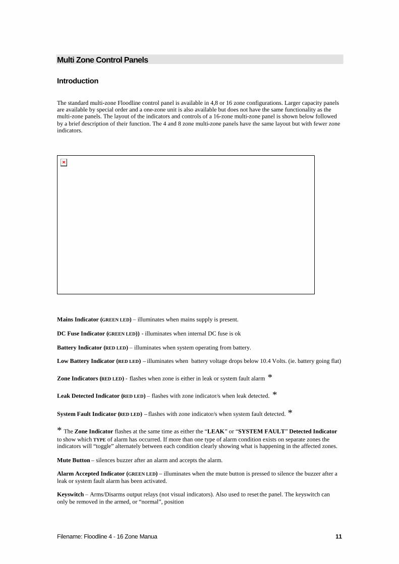
The standard multi-zone Floodline control panel is available in 4,8 or 16 zone configurations. Larger capacity panelsare available by special order and a one-zone unit is also available but does not have the same functionality as themulti-zone panels. The layout of the indicators and controls of a 16-zone multi-zone panel is shown below followedby a brief description of their function. The 4 and 8 zone multi-zone panels have the same layout but with fewer zoneindicators.
Mains Indicator (GREEN LED) – illuminates when mains supply is present.
DC Fuse Indicator (GREEN LED)) - illuminates when internal DC fuse is ok
Battery Indicator (RED LED) – illuminates when system operating from battery.
Low Battery Indicator (RED LED) – illuminates when battery voltage drops below 10.4 Volts. (ie. battery going flat)
Zone Indicators (RED LED) - flashes when zone is either in leak or system fault alarm *
Leak Detected Indicator (RED LED) – flashes with zone indicator/s when leak detected. *
System Fault Indicator (RED LED) – flashes with zone indicator/s when system fault detected. *
* The Zone Indicator flashes at the same time as either the “LEAK” or “SYSTEM FAULT” Detected Indicatorto show which TYPE of alarm has occurred. If more than one type of alarm condition exists on separate zones theindicators will “toggle” alternately between each condition clearly showing what is happening in the affected zones.
Mute Button – silences buzzer after an alarm and accepts the alarm.
Alarm Accepted Indicator (GREEN LED) – illuminates when the mute button is pressed to silence the buzzer after aleak or system fault alarm has been activated.
Keyswitch – Arms/Disarms output relays (not visual indicators). Also used to reset the panel. The keyswitch canonly be removed in the armed, or “normal”, position

Filename: Floodline 4 - 16 Zone Manua 12
Mounting the Floodline Panel
The Floodline multi-zone control panel is mounted on the wall surface. Raised mounting bosses in the rear of the caseat each corner allow fixing with wood screws or bolts etc. A “key- slot” is provided in the back/top of the case toenable the control panel to be hung temporally on 1 fixing for levelling and marking of the mounting bosses. Thecontrol panel should be fixed at a convenient level for inspection level and to ensure that the mute button, keyswitchand door release fastening are accessible. 20mm cable entry points are provided in the top, bottom and rear faces ofthe case.
!,1. Under no circumstances should additional holes be made in the enclosure without first
carefully removing both circuit boards.
2. This equipment is for indoor use only
3. The ventilation holes is the sides of the unit must not be covered and a gap of 25mmbetween the sides of the panel and any other surface must be maintained.
Connection of Mains Supply
!,1. The mains supply to the Floodline control panel is 220/240Vac 50/60Hz or 110/120 50/60Hz
and should be via a dedicated fused spur fitted with a 3 Amp fuse. The supply voltagerange is set at time of manufacture and the voltage range selected is clearly mark on themains terminal cover.
2. The cable for connection to the mains supply must be 3 core mains cable rated at no lessthan 3A (0.5mm2) and must be fitted via a gland which includes strain relief for the cable
3. Screw terminals are situated at the top left-hand edge of the circuit board in the rear of thecase for the connection of the mains supply. These terminals are clearly labelled Live,Neutral and Earth.
4. Caution red mains cover and warning label must be replaced once the mains has beenwired into the mains terminals.
5. Warning this equipment must be earthed The Floodline multi-zone panel must providedwith an Earth (Ground) to ensure correct operation and safety reasons. If the panel is notcorrectly earthed (grounded) Andel Limited cannot guarantee correct operation of thesystem.
Filename: Floodline 4 - 16 Zone Manua 13
Battery Connection or Replacement
The panel is supplied with a rechargeable 12V 1.2Ah (or 1.3Ah) lead acid battery, which should be connected oncethe panel has been installed. The cable for connection to the battery and the terminals of the battery are colour codered for battery positive and black for 0Volts.
!,1. Warning isolate mains supply before opening panel door for connecting of replacement
battery.
2. Warning the battery is live at all times take care not to short the battery terminals
3. Warning check that the colours from the battery leads and the battery terminals matchbefore connecting.
4. Caution the battery contains substances harmful to the environment and should not bedisposed of in normal waste and should be returned to the supplier, or disposed of using aappropriate authorised contractor.
Connection of Leak Detection Sensors
!,Warning Sensor connection should only be carried out once the mains supply has been isolated byremoving the fuse from the fused spur feeding the panel and with the battery disconnected
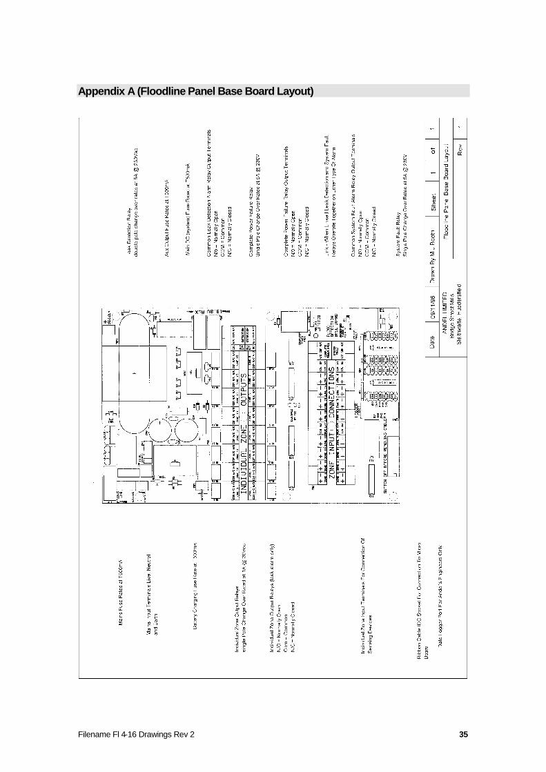
Incoming wires from the detection devices are connected to the “Zone Input “ terminals within the panel (see “Floodline Panel Base Board Layout”). “Sleeper” resistors are factory fitted across the +ve and -ve terminals of eachzone’s input terminals for testing and transport purposes and should be removed as each zone is connected. The“sleeper” resistors are left in place in any unused zones.
“Sleeper” resistors are 1Mand simulate the end-of-line resistor built into some devices e.g. Multi-Zone CableJunction Boxes, Oil Sensors and Pipe-in-Pipe Sensors - no additional end-of-line resistor is needed in those devices.Point Sensors or Flexi-Pad Sensors DO require an end-of-line resistor fixing into the last device in line in a zone (orthe only device if there is just one in the zone). For convenience the “sleeper” resistors can be used for this purposeand can be taken from the zone input terminals and fixed into the output terminals of the last, or only, device.
The specific installation and wiring details of each of the sensor is detailed in latersections.
Initial Power up
Once all detection devices and networks have been connected to the multi-zone Floodline control panel, initialpower-up can take place. On power up (either mains or battery) the panel will perform a brief self- test in which allindicators, relays and buzzer are sequentially and then simultaneously operated. After the self-test routine iscompleted the panel automatically enters normal monitoring mode.

Filename: Floodline 4 - 16 Zone Manua 14
Normal Operating Mode
In normal operating mode the “DC fuse” indicator (GREEN LED) should be illuminated along with the “mains”(GREEN LED) indicator. In the event of mains failure the system can perform normally from a healthy battery“battery” (RED LED) but mains power should be restored as a matter of urgency. In normal operation the CompletePower Failure Relay will be activated (ie. energised or “picked”). This is normal and it is strongly recommendedthat this relay should be connected to the any remote monitoring system, BMS etc. along with the other alarmoutputs. In the event of only a “common” alarm being used we strongly recommend that for “circuit break”monitoring the common connection is made in series made through the common terminal and normally open terminalof the complete power failure relay and for “circuit make” monitoring a parallel connection is made with the commonterminal and the normally closed terminal.
Note It is good practice to check the two green led indicators on a daily basis
Note Use the Complete Power Failure Relay as part of a “common alarm” connection
Leak Detection Alarms
The panel generates a leak alarm when the loop resistance of any zone falls below the Leak threshold. Once a leakalarm has occurred the indicator for the affected zone will flash in unison with the Leak indicator (RED LED). At thesame time the buzzer will sound, the common leak detection relay will activate and the individual zone output relaywill also activate (if fitted).
Note In addition to the main Leak Detection Relay the System Fault Relay can bemade to activate at the same time if the blue link just below the Complete PowerFailure relay on the Floodline Panel’s Base Board is made.
The diagram below shows the fascia of the Floodline multi-zone control panel with a leak alarm active in zone 1.
Zone & Leak Indicator FlashingIndicating A leak AlarmIn Zone one
These 2 Green IndicatorsMust Be illuminated
Filename: Floodline 4 - 16 Zone Manua 15
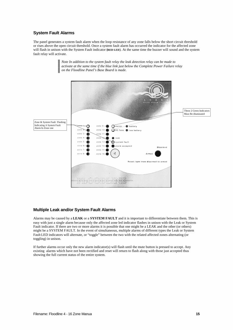
System Fault Alarms
The panel generates a system fault alarm when the loop resistance of any zone falls below the short circuit thresholdor rises above the open circuit threshold. Once a system fault alarm has occurred the indicator for the affected zonewill flash in unison with the System Fault indicator (RED LED). At the same time the buzzer will sound and the systemfault relay will activate.
Note In addition to the system fault relay the leak detection relay can be made toactivate at the same time if the blue link just below the Complete Power Failure relayon the Floodline Panel’s Base Board is made.
Zone & System Fault FlashingIndicating A System FaultAlarm In Zone one
These 2 Green IndicatorsMust Be illuminated
Multiple Leak and/or System Fault Alarms
Alarms may be caused by a LEAK or a SYSTEM FAULT and it is important to differentiate between them. This iseasy with just a single alarm because only the affected zone led indicator flashes in unison with the Leak or SystemFault indicator. If there are two or more alarms it is possible that one might be a LEAK and the other (or others)might be a SYSTEM FAULT. In the event of simultaneous, multiple alarms of different types the Leak or SystemFault LED indicators will alternate, or “toggle” between the two with the related affected zones alternating (ortoggling) in unison.
If further alarms occur only the new alarm indicator(s) will flash until the mute button is pressed to accept. Anyexisting alarms which have not been rectified and reset will return to flash along with those just accepted thusshowing the full current status of the entire system.

Filename: Floodline 4 - 16 Zone Manua 16
Control Panel Internal Condition Alarms
The control panel monitors external, internal and battery back-up power supply conditions.
Mains Fails – External mains supply to the panel fails. Mains indicator (GREEN LED) on the front of the panel willextinguish and the battery indicator (RED LED) will illuminate.
Low Battery – When the panel is running from the battery and its voltage falls below 10.4 volts (ie. going flat) thelow battery indicator will illuminate (RED LED ) and the buzzer will pulse every 30 seconds. This will only last a shorttime.
Complete Power Failure – Both the mains supply and battery back- up have failed. The complete power failurerelay will “drop” when such an alarm is generated.
DC Fuse Failure – The DC fuse supplies all the power to the control electronics. If this fuse fails the normallyilluminated DC fuse indicator (GREEN LED) will extinguish and the complete power failure relay will de-energiseor“drop”.
Check the two GREEN Mains and DC Fuse LEDs regularly
Silencing the Audible Alarm (Buzzer)
Pressing the mute button silences the buzzer. This does not change the state of the other alarm indicators but thealarm accepted indicator (GREEN LED) will illuminate to show that the last alarm has been acknowledged. Should anynew alarm occur the buzzer will re-activate and the new alarm will assume priority. The control panel will accept anddisplay further alarms even if the last alarm has not been muted (accepted).
Resetting the Panel
To reset the panel rectify all alarm conditions* - insert key - turn to disarmed – return to armed position and remove.* it may not be possible to rectify all alarm conditions at one time Should any zone still be wet or in another alarmcondition it will return within seconds of the panel being reset. The system can be left with an alarm activeindefinitely with no detrimental affect on it ability to monitor normally in the unaffected zones.
After a reset action the control panel will always return to normal,“quiet” mode for atleast a few seconds before reacting to any residual, un-cleared alarms.
Multi-Zone Panel Alarm Output Relays
The multi-zone Floodline panel is fitted with three relays, which provide volt-free contacts for complete powerfailure, leak and system fault alarms. These volt-free contacts can be used for connection to BMS etc. The completepower failure and system fault alarm relays have single pole change over contacts and are rated at 5A at 230Vac. Theleak alarm relay has double pole change over contacts and each contact is rated at 5A at 230Vac.
If mains voltage is to be switched by the relay contacts then under the Low VoltageDirective the terminals must be fitted with appropriate covers and warning labels.
The leak detected and system fault relays can be set to mimic each others operation byconnecting the blue link on the panel base PCB. The blue link is located just below thecomplete power failure relay (see Floodline Panel Base-Board Layout in Appendix A).

Filename: Floodline 4 - 16 Zone Manua 17
As an optional extra in addition to the “common” relays each zone in the multi-zone panel may have an independentsingle pole change over relay rated at 1A 30Vdc. These can be fitted when more comprehensive onwardscommunications is needed. These individual zone output relays only operate when a leak alarm has been detected inits corresponding zone.
Adjusting Floodline Panel Sensitivity
!,Warning disconnect mains supply before opening panel door
In certain areas and applications it may be necessary to reduce the sensitivity of the system to avoid spurious alarmscaused by “background” dampness, inherent humidity etc. The only noticeable difference in operation may be a slightdelay between detection and alarm. This time delay will be more pronounced in testing when only a small area ofcable is wetted.
Panels are shipped with the sensitivity set at 300k. This can be lowered immediately to 200k - 100k if site conditionsdictate, or can be progressively lowered at any time following installation. The sensitivity may need to be adjusted to“filter out” background damp or minor drips and can also be used to increase the amount of water needed to touch thesensor before the alarm is activated.
Sensitivity adjustment can be made by moving the two jumper links on the smaller circuit board mounted on the backof the control panel door. The two links must be moved together, as a pair, up or down the matching banks of pinswhich are clearly marked 200 – 25. The top setting (not marked) is 300k.
The sensitivity can not be lowered below 200k if standard Point, pipe-in-pipe or Flexi-Pad sensors are used. Modifications to these sensors are required if they are to beoperated from a reduced sensitivity control panel.
Technical Specification
Electrical
Supply Voltage = 230Vac 50/60Hz (110ac version available)
Rated Current (Maximum) = 109mA
Fuse Type (FS1,2,3,4) = 20x5mm 250Vac 500mA Type T
Panel Dimensions Height = 292mm
Width = 285mm
Depth = 90mm
Environment
Operating Temperature 0o C – 40o C
Cooling Method Convection
Filename: Floodline 4 - 16 Zone Manua 18
Maintenance
!,Warning disconnect mains supply before undertaking any maintenance work within theequipment.
User Maintenance – Day to Day
The correct functioning of the system can be verified on a day to day basis by observation of the two green LEDindicators for Mains and DC Fuse. Both LED’s must be lit for correct operation.
Note must be taken of any SYSTEM FAULT alarms or indicators and any other red LED’s i.e. BATTERY or LOWBATTERY. The manufacture or installer must be informed immediately of any of these events
Yearly Maintenance
To ensure correct operation of the system in the long term Andel Limited advice that the system should be (as aminimum) maintained on a yearly basis.
The maintenance schedule should include the following
Panel function test Battery test
Zone testing of the entire installation. This should comprise taking resistance reading of each zone (using an analoguemetre only) from the control panel position (with the zone disconnected) and a comparison made, to identify anyanomalies, against a standard alarm/detection threshold. Any anomalous results should be recorded and a physicalinspection made of those zones.Cable Location Verification: A sample of 25% of the zones should be physically checked at two points along theirextent for correct cable/sensing device positioning in accordance with the original design. Should any variance befound it should be sufficiently investigated to establish an overall picture
Filename: Floodline 4 - 16 Zone Manua 19
Single Zone Detection (Sensing) Tape
Introduction
The Single Zone Detection Tape is the simplest of all the Floodline detection sensors and is a low cost solution wherelarge amounts of basic leak detection is required. It is very absorbent, and will therefore react to the smallest amountof liquid. Water is sensed anywhere along its entire length and typical application include:
Suspending above ceiling.
Tie-wrapped to individual pipes.
Laid below raised floors.
Run in drip trays.
Laid around the base of an item of plant, apparatus or tank.
Laid in loops or wave pattern for general monitoring of large areas.
As with all Floodline sensors water contacting the tape changes its electrical characteristics (resistance) and when thechange is sufficient the Floodline panel, to which the sensor is connected will generate the appropriate alarm.
The single zone tape is 20mm wide and 3mm thick and has a woven polyester construction which makes it bothdurable and resistant to abrasion.
The single zone detection tape although durable is a sensing device and should betreated as such
Fixing
The single zone detection tape can be fixed to the floor or other surface with loose fitting flat ribbon cable type clips,self-adhesive clips or tie-wraps. Once the detection tape is laid identification/warning labels should be attached atregular intervals to identify the zone and warn of its function.
Connecting to Floodline Panel
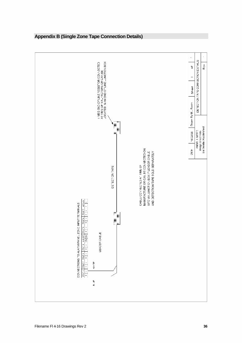
The single zone detection tape can be directly connected to the zone input terminals of the Floodline panel however itis more practical to run 2 core (minimum) leader cable from the panel position to the start of the area where thedetection tape is needed. Connection from the leader cable to the detection tape may be made using a standard 4 wayFloodline Junction Box (see later). The specification of the leader cable from the panel to the start of the detectiontape is standard PVC/PVC 0.2 multi-core alarm/comms type cable or similar. LSF of other light cables can besubstituted if required.
A diagram of the connection details between the Floodline panel and the single zonedetection tape is presented in Appendix B
Returning Sensor to Use
The single zone detection tape can be wetted and dried any number of times as long as it does not becomecontaminated with a substance which irrevocably changes its electrical characteristics. Eg.vending machine syrup,some chemical floor treatments, paint etc. The detection tape will dry out naturally and the effected part of the cablemust be completely dry before the zone can be reset. This may take 20 minutes to 2 hours or more depending on theenvironmental conditions and the length of tape wetted but increased air circulation and warmth will speed up dyingtime. If a length of tape seems to take an excessive time to dry out water may be trapped in the retaining clips whichshould be eased to expose the wet area to the air.
The tape may be damaged if it is completely immersed for long periods. In the event of this, or any other damageonly the affected section of tape (either all or part of a zone) need be replaced with a new length of detection tapeeasily jointed in.
Filename: Floodline 4 - 16 Zone Manua 20
Multi –4-Zone Detection (Sensing) Cable
Introduction
The Multi-4-Zone Detection Cable is more sensitive than the Multi- 8 Zone version. It senses water anywhere alongits entire length and one continuous length of cable can be divided into 4 separately reporting zones using specialFloodline 4 Zone Junction Boxes. Typical applications include:
In voids below raised floors.
Above Suspended Ceilings
Tie-wrapped to individual pipes.
Run in drip trays.
Laid around the base of plant, apparatus or tank.
Laid in loops or wave pattern for general monitoring of larger areas.
No minimum or maximum zone length.
As with all Floodline sensors water contacting the cable changes its electrical characteristics (resistance) and whenthe change is sufficient the Floodline panel, to which the sensor is connected will generate the appropriate alarm.
The multi-4- zone detection cable has an oval construction of 4.5mm by 7.5mm. The outer braid of the sensor is of awoven polyester construction, which makes it durable and resistant to abrasion. The inner cores of the sensor arePVC/PVC and the detection cores, which are used to monitor the changes in the sensors electrical characteristics arewrapped in a permeable non-woven cellulosic material.
The multi-4-zone detection (sensing) cable although durable is a sensing device andshould be treated as such
Fixing
The detection cable is laid flat on the floor in the pre-determined pattern and special 4 Zone Junction Boxes are usedto connect the detection cable “string” to the leader cable coming form the control panel and at the start of eachsubsequent zone in turn. A further junction box is used at the end of line. The detection cable is usually fixed withscrewed “P” type clips or pin-plugged “Tower” type clips. Both these techniques involve drilling and although self-adhesive clips or hot-melt adhesive clips may be used they are only possible when the surface is clean, dry and non-friable. Clips are usually spaced at 3m intervals and must hold the cable loosely to allow air to circulate around thecable. Once the detection cable is laid identification/warning tags should be attached at 3m intervals to identify thezone and warn of its function.
Connecting to Floodline Panel and Junction Boxes
The Multi-4-Zone Detection cable can be directly connected to the zone inputs terminals of the Floodline panelhowever it is more practical to run 5 core (minimum) leader cable from the panel position to the start of the areawhere the detection cable is needed. The specification of the leader cable from the panel to the start of the detectioncable is standard PVC/PVC 7/0.2 multi-core alarm/comms type cable or similar. LSF of other light cables can besubstituted if required.
A diagram of the connection details for the multi –4-zone detection cable is presentedin Appendix C
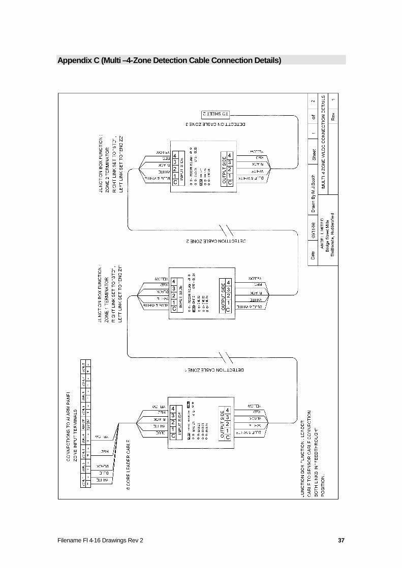
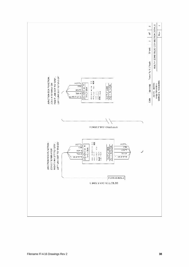
The special Junction Boxes are used to connect the leader cable from the control panel to the start of the detectioncable string; as zone change device and as end of line terminator. The function of each junction box is determined bythe positioning of the two jumper links within the unit. More detailed reference to the positioning of the jumper linksetc. appear in the diagram in Appendix C.
Filename: Floodline 4 - 16 Zone Manua 21
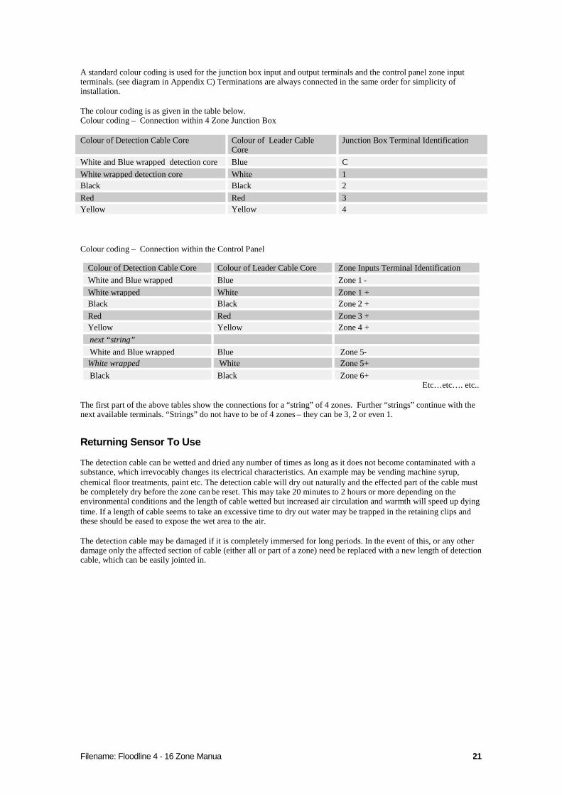
A standard colour coding is used for the junction box input and output terminals and the control panel zone inputterminals. (see diagram in Appendix C) Terminations are always connected in the same order for simplicity ofinstallation.
The colour coding is as given in the table below.Colour coding – Connection within 4 Zone Junction Box
Colour of Detection Cable Core Colour of Leader CableCore
Junction Box Terminal Identification
White and Blue wrapped detection core Blue CWhite wrapped detection core White 1Black Black 2Red Red 3Yellow Yellow 4
Colour coding – Connection within the Control Panel
Colour of Detection Cable Core Colour of Leader Cable Core Zone Inputs Terminal IdentificationWhite and Blue wrapped Blue Zone 1 -White wrapped White Zone 1 +Black Black Zone 2 +Red Red Zone 3 +Yellow Yellow Zone 4 +next “string”White and Blue wrapped Blue Zone 5-White wrapped White Zone 5+Black Black Zone 6+
Etc…etc…. etc..
The first part of the above tables show the connections for a “string” of 4 zones. Further “strings” continue with thenext available terminals. “Strings” do not have to be of 4 zones – they can be 3, 2 or even 1.
Returning Sensor To Use
The detection cable can be wetted and dried any number of times as long as it does not become contaminated with asubstance, which irrevocably changes its electrical characteristics. An example may be vending machine syrup,chemical floor treatments, paint etc. The detection cable will dry out naturally and the effected part of the cable mustbe completely dry before the zone can be reset. This may take 20 minutes to 2 hours or more depending on theenvironmental conditions and the length of cable wetted but increased air circulation and warmth will speed up dyingtime. If a length of cable seems to take an excessive time to dry out water may be trapped in the retaining clips andthese should be eased to expose the wet area to the air.
The detection cable may be damaged if it is completely immersed for long periods. In the event of this, or any otherdamage only the affected section of cable (either all or part of a zone) need be replaced with a new length of detectioncable, which can be easily jointed in.
Filename: Floodline 4 - 16 Zone Manua 22
Multi -8-Zone Detection (Sensing) Cable
Introduction
The multi-8-zone detection cable is the least sensitive of all the Floodline tape/cable detection sensors. It senses wateranywhere along its entire length and one continuous length of cable can be divided into 8 separately reporting zonesusing special Floodline 8 Zone Junction Boxes. Typical applications include:
In voids below raised floors.
Above Suspended Ceilings
Run in drip trays.
Laid around the base of plant, apparatus or tank.
Laid in loops or wave pattern for general monitoring of larger areas.
No minimum or maximum zone length.
The multi-8-zone detection cable should not be tie-wrapped to pipes (– use multi-4Zone detection cable instead)
As with all Floodline sensors water contacting the cable changes its electrical characteristics (resistance) and whenthe change is sufficient the Floodline control panel, to which the sensor is connected will generate the appropriatealarm.
The multi-8- zone detection cable has an outside diameter of 6mm. A tough all polymeric construction makes ittough, durable and resistant to abrasion but it is also flexible enough to lie flat or be easily shaped.
Although tough and durable the multi-8-zone detection cable is a sensing device andshould be treated as such
Fixing
The multi-8-zone detection cable is laid flat on the floor in the pre-determined pattern and special 8 Zone JunctionBoxes are used to connect the detection cable “string” to the leader cable coming from the control panel and at thestart of each subsequent zone in turn. A further junction box is used at the end of line. The detection cable is usuallyfixed with screwed “P” type clips or pin-plugged “Tower” type clips. Both these techniques involve drilling andalthough self-adhesive clips or hot-melt adhesive clips may be used they are only possible when the surface is clean,dry and non-friable. Clips are usually spaced at 3m intervals and must hold the cable loosely to allow air to circulatearound the cable. Once the detection cable is laid identification/warning tags should be attached at 3m intervals toidentify the zone and warn of its function.
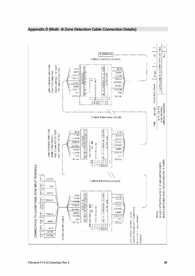
Connecting to Floodline Panel and Junction Boxes
The Multi-8-Zone Detection Cable can be directly connected to the zone input terminals within the Floodline controlpanel however it is more practical to run 9 core (minimum) leader cable from the panel position to the start of thearea where the detection cable is needed. The specification of the leader cable from the panel to the start of thedetection cable is standard PVC/PVC 7/0.2 multi-core alarm/comms type cable or similar. LSF of other light cablescan be substituted if required.
A diagram of the connection details for the multi–8-zone detection cable is presented inAppendix D
The special Junction Boxes are used to connect the leader cable from the control panel to the start of the detectioncable string; as zone change device and as end of line terminator. The function of each junction box is determined bythe positioning of the two jumper links within the unit. More detailed reference to the positioning of the jumper linksetc. appear in the diagram in Appendix D.

Filename: Floodline 4 - 16 Zone Manua 23
A standard colour coding is used for the junction boxes input and output terminals and the control panel’s zone inputterminals (as indicated on the diagrams in Appendix D). Terminations are always connected in the same order forsimplicity of installation. The following procedure must be followed for splicing in the junction boxes:-
Note: The two black cores must not touch. If the two black cores do touch thenthe control panel will generate a system fault alarm.
Colour coding – Connection within 8 Zone Junction Box
Colour of Detection Cable Core Colour of Leader Cablecore
Junction Box Terminal Identification
Yellow Yellow 8Red Red 7Black 2 (Between Yellow and WhiteCores)
Brown 1
Green Green 6Orange Orange 5Purple Purple 4Black 1 (Between Blue and Green Cores) Black CWhite White 3Blue Blue 2
Filename: Floodline 4 - 16 Zone Manua 24
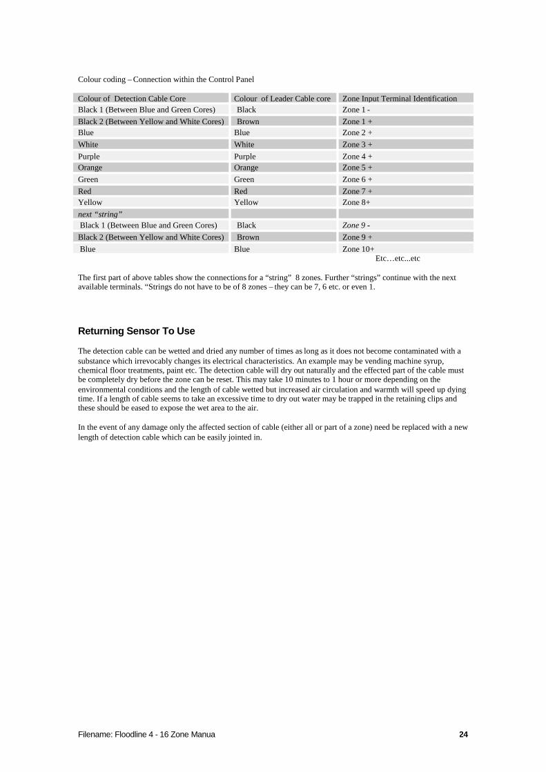
Colour coding – Connection within the Control Panel
Colour of Detection Cable Core Colour of Leader Cable core Zone Input Terminal IdentificationBlack 1 (Between Blue and Green Cores) Black Zone 1 -Black 2 (Between Yellow and White Cores) Brown Zone 1 +Blue Blue Zone 2 +White White Zone 3 +Purple Purple Zone 4 +Orange Orange Zone 5 +Green Green Zone 6 +Red Red Zone 7 +Yellow Yellow Zone 8+next “string”Black 1 (Between Blue and Green Cores) Black Zone 9 -Black 2 (Between Yellow and White Cores) Brown Zone 9 +Blue Blue Zone 10+
Etc…etc...etc
The first part of above tables show the connections for a “string” 8 zones. Further “strings” continue with the nextavailable terminals. “Strings do not have to be of 8 zones – they can be 7, 6 etc. or even 1.
Returning Sensor To Use
The detection cable can be wetted and dried any number of times as long as it does not become contaminated with asubstance which irrevocably changes its electrical characteristics. An example may be vending machine syrup,chemical floor treatments, paint etc. The detection cable will dry out naturally and the effected part of the cable mustbe completely dry before the zone can be reset. This may take 10 minutes to 1 hour or more depending on theenvironmental conditions and the length of cable wetted but increased air circulation and warmth will speed up dyingtime. If a length of cable seems to take an excessive time to dry out water may be trapped in the retaining clips andthese should be eased to expose the wet area to the air.
In the event of any damage only the affected section of cable (either all or part of a zone) need be replaced with a newlength of detection cable which can be easily jointed in.
Filename: Floodline 4 - 16 Zone Manua 25
M8 Detection Cable (Plug & Play)
Introduction
The M8 detection cable is the least sensitive of all the Floodline tape/cable detection sensors. It senses wateranywhere along its entire length typical applications include:
In voids below raised floors.
Run in drip trays.
Laid around the base of plant, apparatus or tank.
Laid in loops or wave pattern for general monitoring of larger areas.
No minimum or maximum zone length.
The M8- detection cable should not be tie-wrapped to pipes (– use M4 detection cableinstead)
As with all Floodline sensors water contacting the cable changes its electrical characteristics (resistance). When thechange is sufficient an appropriate alarm will be generated at the Floodline panel.
The M8 detection cable has an outside diameter of 4.5mm. A tough all LSOH polymeric construction makes ittough, durable and resistant to abrasion but it is also flexible enough to lie flat or be easily shaped.
Although tough and durable the multi-8-zone detection cable is a sensing device andshould be treated as such
The M8 detection cable is available in 5,7.5, 10, 15 and 30m lengths as standard (different lengths can be made toorder) and simply plug into the special plug and play junction box (see below for connecting details) this makeinstallation of the system quicker and simpler.
Fix & Connecting to Floodline Panel and Junction Boxes
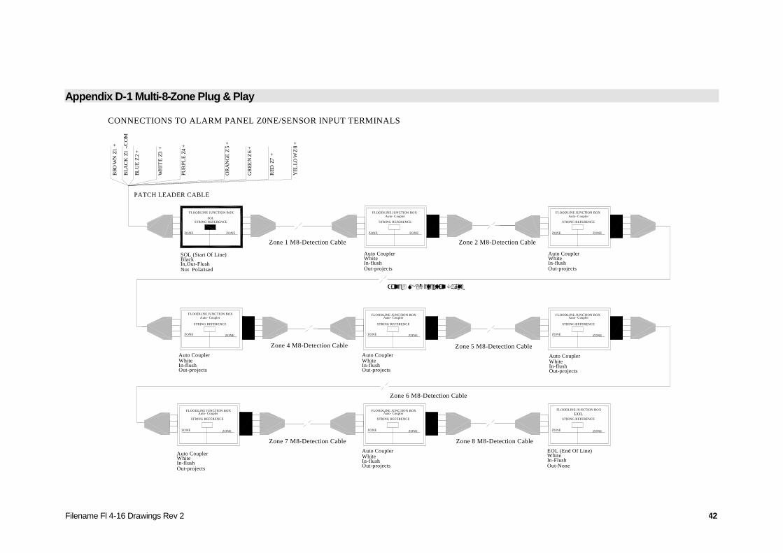
The multi-8-zone detection cable is laid flat on the floor in the pre-determined pattern. A SOL Junction Box is usedto connect the detection cable “string” to the leader cable coming from the control panel and Auto-coupler JunctionBoxes are used to split the cable into separately reporting zones (up to 8 zone per-string). At the end of line an EOLJunction Box is used to terminate the string .
A diagram of the connection details for the M8 Plug and Play sensors is presented inAppendix D-1
The detection cable is usually fixed with screwed “P” type clips or pin-plugged “Tower” type clips. Both thesetechniques involve drilling and although self-adhesive clips or hot-melt adhesive clips may be used, they are onlypossible when the surface is clean, dry and non-friable. Clips are usually spaced at 3m intervals and must hold thecable loosely to allow air to circulate around the cable. Once the detection cable is laid, identification/warning tagsshould be attached at 3m intervals to warn of its function.
Filename: Floodline 4 - 16 Zone Manua 26
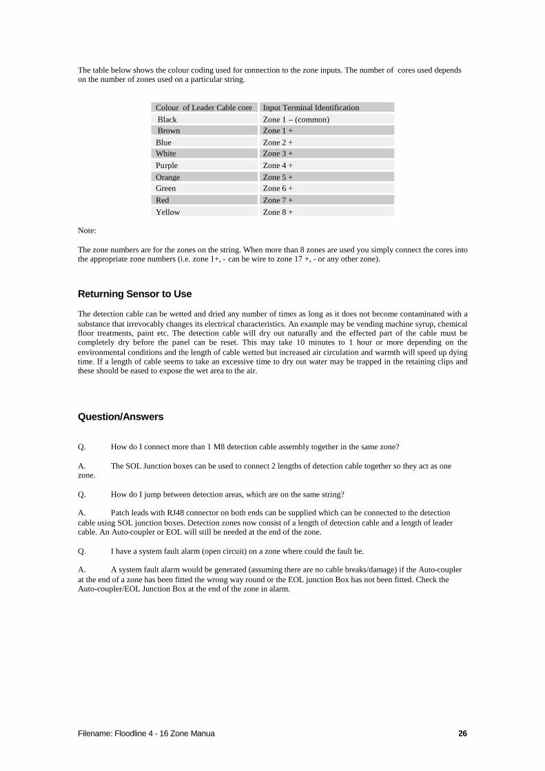
The table below shows the colour coding used for connection to the zone inputs. The number of cores used dependson the number of zones used on a particular string.
Colour of Leader Cable core Input Terminal IdentificationBlack Zone 1 – (common)Brown Zone 1 +Blue Zone 2 +White Zone 3 +Purple Zone 4 +Orange Zone 5 +Green Zone 6 +Red Zone 7 +Yellow Zone 8 +
Note:
The zone numbers are for the zones on the string. When more than 8 zones are used you simply connect the cores intothe appropriate zone numbers (i.e. zone 1+, - can be wire to zone 17 +, - or any other zone).
Returning Sensor to Use
The detection cable can be wetted and dried any number of times as long as it does not become contaminated with asubstance that irrevocably changes its electrical characteristics. An example may be vending machine syrup, chemicalfloor treatments, paint etc. The detection cable will dry out naturally and the effected part of the cable must becompletely dry before the panel can be reset. This may take 10 minutes to 1 hour or more depending on theenvironmental conditions and the length of cable wetted but increased air circulation and warmth will speed up dyingtime. If a length of cable seems to take an excessive time to dry out water may be trapped in the retaining clips andthese should be eased to expose the wet area to the air.
Question/Answers
Q. How do I connect more than 1 M8 detection cable assembly together in the same zone?
A. The SOL Junction boxes can be used to connect 2 lengths of detection cable together so they act as onezone.
Q. How do I jump between detection areas, which are on the same string?
A. Patch leads with RJ48 connector on both ends can be supplied which can be connected to the detectioncable using SOL junction boxes. Detection zones now consist of a length of detection cable and a length of leadercable. An Auto-coupler or EOL will still be needed at the end of the zone.
Q. I have a system fault alarm (open circuit) on a zone where could the fault be.
A. A system fault alarm would be generated (assuming there are no cable breaks/damage) if the Auto-couplerat the end of a zone has been fitted the wrong way round or the EOL junction Box has not been fitted. Check theAuto-coupler/EOL Junction Box at the end of the zone in alarm.
Filename: Floodline 4 - 16 Zone Manua 27
Point Sensors (Horizontal and Vertical)
Introduction
Floodline Point Sensors are designed to operate in areas where detection cable/tape could be damaged or where somedamp, minor wetting or spillage is expected or of little concern e.g. plant room, basement or tunnel. Water must touchthe point sensor probes to activate the alarm. Point Sensors are normally used in conjunction with a powder-coatedsteel Floodline Guard Plate which gives heavy-duty physical protection and assists fixing and adjustment. The pointsensor can be used singly in one zone or in-groups with a number of sensors being connected together and acting asone zone.
Dimensions - 71mm high x 44mm wide x 25mm deep.(when mounted in the Guard Plate) - 110mm high x 102mm wide x 30mm deep (viewedvertically).
Fixing
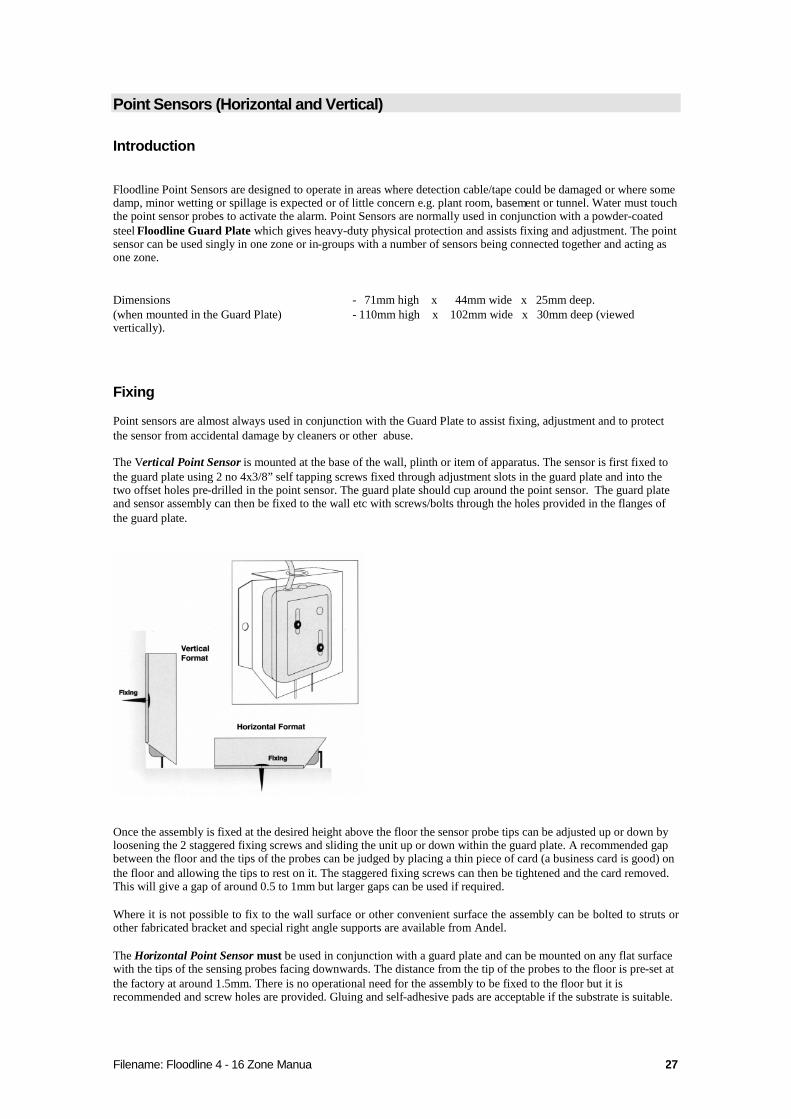
Point sensors are almost always used in conjunction with the Guard Plate to assist fixing, adjustment and to protectthe sensor from accidental damage by cleaners or other abuse.
The Vertical Point Sensor is mounted at the base of the wall, plinth or item of apparatus. The sensor is first fixed tothe guard plate using 2 no 4x3/8” self tapping screws fixed through adjustment slots in the guard plate and into thetwo offset holes pre-drilled in the point sensor. The guard plate should cup around the point sensor. The guard plateand sensor assembly can then be fixed to the wall etc with screws/bolts through the holes provided in the flanges ofthe guard plate.
Once the assembly is fixed at the desired height above the floor the sensor probe tips can be adjusted up or down byloosening the 2 staggered fixing screws and sliding the unit up or down within the guard plate. A recommended gapbetween the floor and the tips of the probes can be judged by placing a thin piece of card (a business card is good) onthe floor and allowing the tips to rest on it. The staggered fixing screws can then be tightened and the card removed.This will give a gap of around 0.5 to 1mm but larger gaps can be used if required.
Where it is not possible to fix to the wall surface or other convenient surface the assembly can be bolted to struts orother fabricated bracket and special right angle supports are available from Andel.
The Horizontal Point Sensor must be used in conjunction with a guard plate and can be mounted on any flat surfacewith the tips of the sensing probes facing downwards. The distance from the tip of the probes to the floor is pre-set atthe factory at around 1.5mm. There is no operational need for the assembly to be fixed to the floor but it isrecommended and screw holes are provided. Gluing and self-adhesive pads are acceptable if the substrate is suitable.

Filename: Floodline 4 - 16 Zone Manua 28
Connecting to the Floodline Panel
All types of Point Sensor will be connected to the zone input terminals of the Floodline control panel via 2 core(minimum) leader cable. The minimum specification of the leader cable from the panel to the point sensor isstandard PVC/PVC 7/0.2mm multi-core alarm/comms type cable or similar. LSF or other light cables can besubstituted if required. A zone can consist of a single point sensor or any number of point sensors connected as a“string” or “daisy-chain”. Input and output terminals are provided in each point sensor to allow for this purpose.
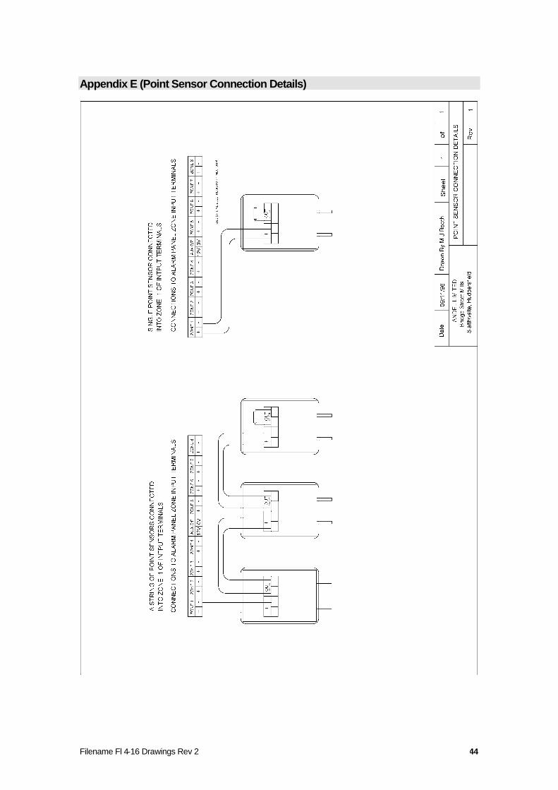
A diagram of the connection details for the point sensors is presented in Appendix E
Once the point sensor, or last sensor in a string has been connected to the leader cable the 1M“sleeper” resistor,from the zone input terminals in the control panel, should be fitted to the output terminals of the point sensor.
Returning Sensor to Use
Point sensors can be wetted and dried any number of times and require no attention after activation unless the wholeunit is immersed. In the event of immersion prompt and thorough drying out will allow immediate return to normaloperating status.
Filename: Floodline 4 - 16 Zone Manua 29
Flexi–Pad Sensor
Introduction
The Floodline Flexi- Pad Sensors have been specifically designed for laying in narrow voids (too small for pointsensors), or wrapped around pipes at valves or joints where leaks are more likely to occur. The flexi- pad sensor canbe used singly in one zone or in groups with a number of sensors being connected together and acting as one zone.
The flexi-pad sensors are made of a tough, flexible plastic sheet 400mm x 300mm x 1mm. A removable fabric coverassists absorption and protects the sensor surface.
Fixing
The sensor can be laid on any flat surface or tie wraps can be used to loosely hold the sensor around a pipe etc.
Connecting to the Floodline Panel
The Flexi-pad sensor/s are connected to the zone input terminals of the Floodline control panel via 2 core (minimum)leader cable. The minimum specification of the leader cable from the panel to the point sensor is standard PVC/PVC7/0.2mm multi-core alarm/comms type cable or similar. LSF or other light cables can be substituted if required. Azone can consist of a single flex-pad sensor or any number of sensors connected as a “string” or “daisy-chain”. Inputand output terminals are provided in each point sensor to allow for this purpose.
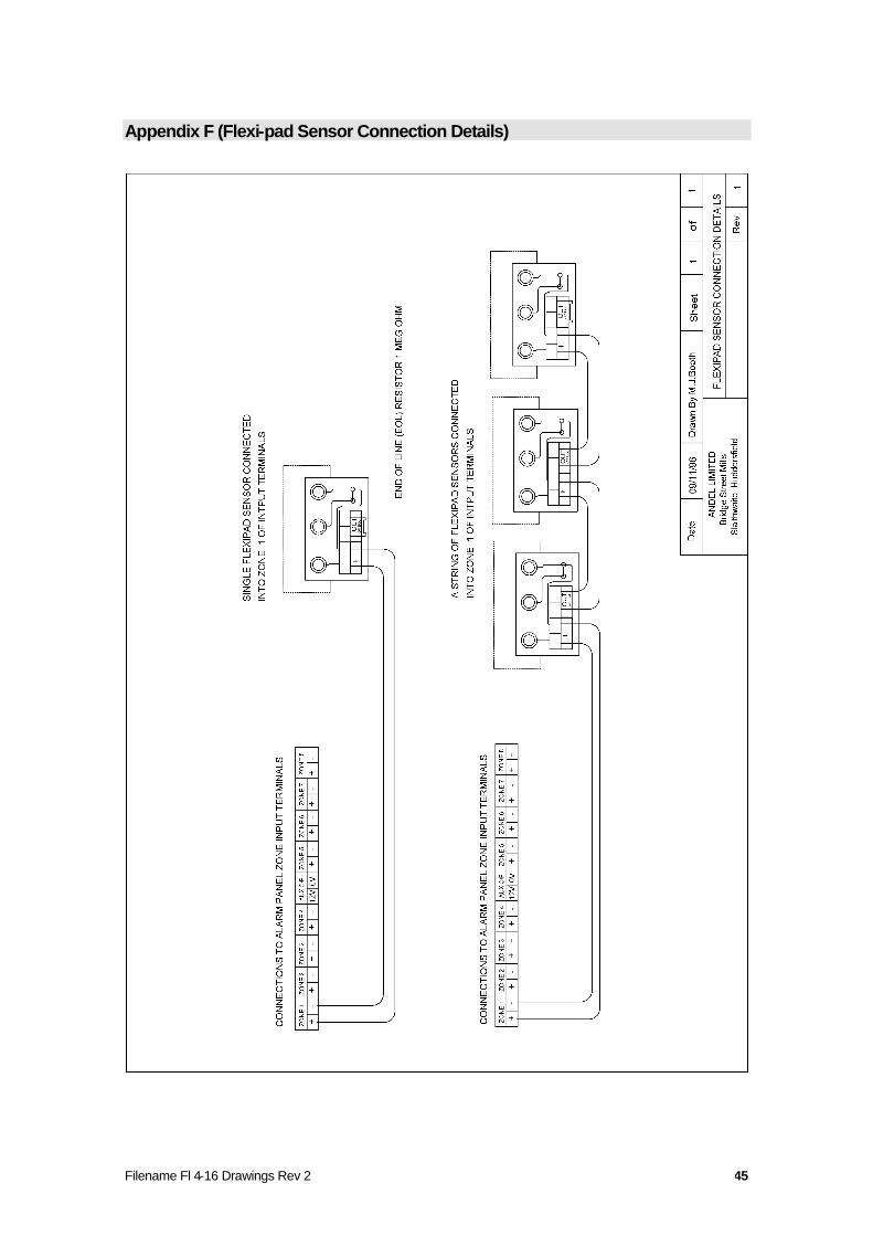
A diagram of the connection details for the flexi-pad sensors is presented in Appendix F
Once the flex- pad sensor, or last sensor in a string has been connected to the leader cable the 1M“sleeper”resistor, from the zone input terminals in the control panel, should be fitted to the output terminals of the point sensor.
Returning Sensor to Use
Flexi-pad sensors can be wetted and dried any number of times provided the sensor element/ fabric cover is notcontaminated with a substance that irrevocably changes its electrical characteristics. An example may be vendingmachine syrup, chemical floor treatments paint etc. After activation the fabric cover can be replaced with a spare orremoved for drying. This would allow the sensor to be returned to use quickly. The sensor can be allowed to drynaturally but this can take some time depending on the environmental conditions and the amount of wetting thatoccurred.
Filename: Floodline 4 - 16 Zone Manua 30
Pipe-in-Pipe Sensor
Introduction
The Floodline Pipe-in Pipe, or double containment, sensor has been specifically designed for use with double skinnedpipes, tanks or other vessels.
The pipe-in-pipe sensors are encapsulated in a high-density plastic body and are fitted with a 5m 4-core leader cable.Dimensions: - 70mm long x 30mm diameter threaded at the base to fit a ½” BSP. Two stainless detection probesprotruded from the threaded base and water contacting these probes activates an alarm. The device can also be usedas a warning “tell -tale” in an overflow pipe.
Fixing
The pipe-in-pipe sensor should be mounted in a pre-drilled and threaded hole in the outer pipe or tank, design toaccept the ½” BSP thread or other suitable flange or boss.
Connecting to the Floodline Panel
The pipe-in-pipe sensor is connected to the zone input terminals of the Floodline control panel via the encapsulated 4-core leader cable. The leader cable to the pipe-in-pipe sensor can be extended using any 2-core PVC/PVC 7/0.2mmalarms/comms type cable. LSF or other light cables can be substituted if required. A zone can consist of a singlesensor but it is possible to connect more than one device to a single zone.
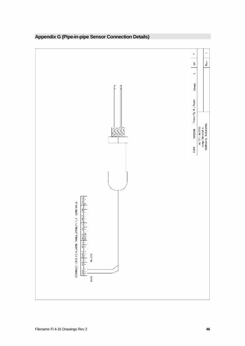
A diagram of the connection details for the pipe-in-pipe sensor is presented inAppendix G
Returning Sensor To Use
The pipe-in-pipe sensors can be wetted and dried any number of times and requires no attention after activation.
Filename: Floodline 4 - 16 Zone Manua 31
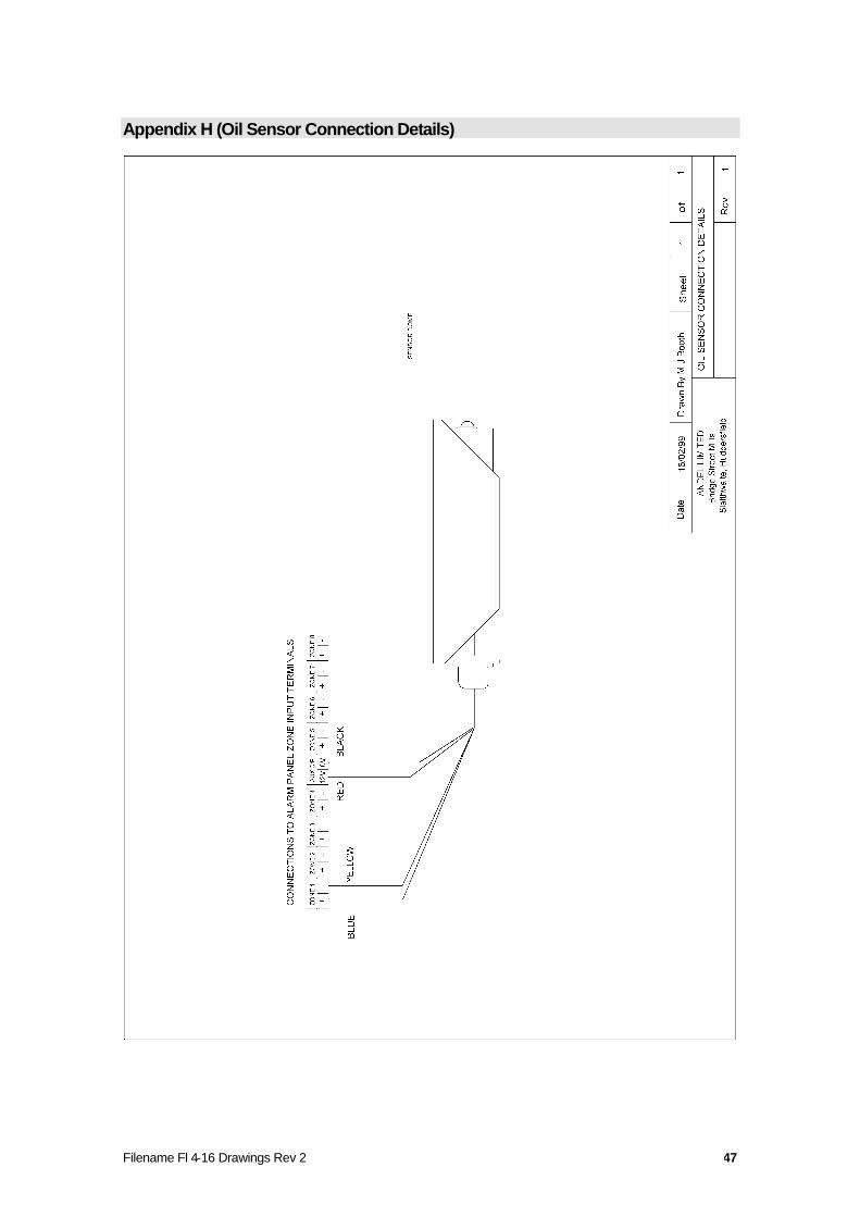
Oil Sensor
Introduction
The Floodline oil sensors can be used with a Floodline Control Panel to provide a dedicated oil leak alarm system oras part a larger water leak detection system. The oil sensor is usually mounted vertically and activates when oil (orany other liquid) touches the infra-red sensing dome at its base. Typical applications include plant rooms where notonly water leaks are possible but also oil and in bunded areas around generator fuel tanks etc. Unlike other Floodlinesensors the Oil Sensor is a powered device which limits the number which can be used with a standard Floodlinecontrol panel. The oil sensor can be used alone or up to a maximum of four can be used in parallel in any one zonewith a maximum of 8 per panel.
The oil sensor is encapsulated and fitted with 5m of 4-core leader cable. It is normally used in conjunction with asteel powder coated Floodline guard plate to give heavy-duty physical protection and assist fixing and adjustment.Dimensions:- 80mm high x 51mm wide x 27mm deep - when mounted in its guard plate -110mm high x 102mmwide x 30mm deep.
Fixing
The oil sensor is mounted at the base of the wall, plinth or item of apparatus. Sensors are fixed to the guard plateusing 2 no 4x3/8” self tapping screws fixed through the adjustment slots into the two holes pre-drilled in the sensor.The guard plate should cup around the oil sensor. The whole assembly can then be fixed to the wall etc withscrews/bolts through the holes in the guard plate flanges.
Once the assembly is fixed at the desired height above the floor the sensor dome tip can be adjusted up or down byloosening the fixing screws and sliding the unit up or down within the guard plate. The dome tip but a small gap canbe judged by placing a thin piece of card (a business card is good) on the floor and allowing the dome to rest on it.The staggered fixing screws can then be tightened and the card removed. This will give a gap of around 0.5 to 1mm.
The area under the dome must be free form debris as if a small amount of moisture oroil builds up in the debris it could cause unwanted activation of the sensor.
Connecting to the Floodline Panel
The oil sensor/s are connected to both the zone input terminals and aux. output terminals within the Floodline multi-zone control panel via the encapsulated 4-core leader cable. The leader cable to the oil sensor can be extended usingany 4-core PVC/PVC 7/0.2mm alarms/comms type cable. LSF or other light cables can be substituted if required. Azone can consist of a single oil sensor or up to 4 sensor can be connected in the same zone (with sensitivity set at200k).
A diagram of the connection details for the oil sensor is presented in Appendix H
Up to a maximum of 8 sensors can be connected to one multi-zone panel. If more are required then an additionalpower supply will have to be supplied.
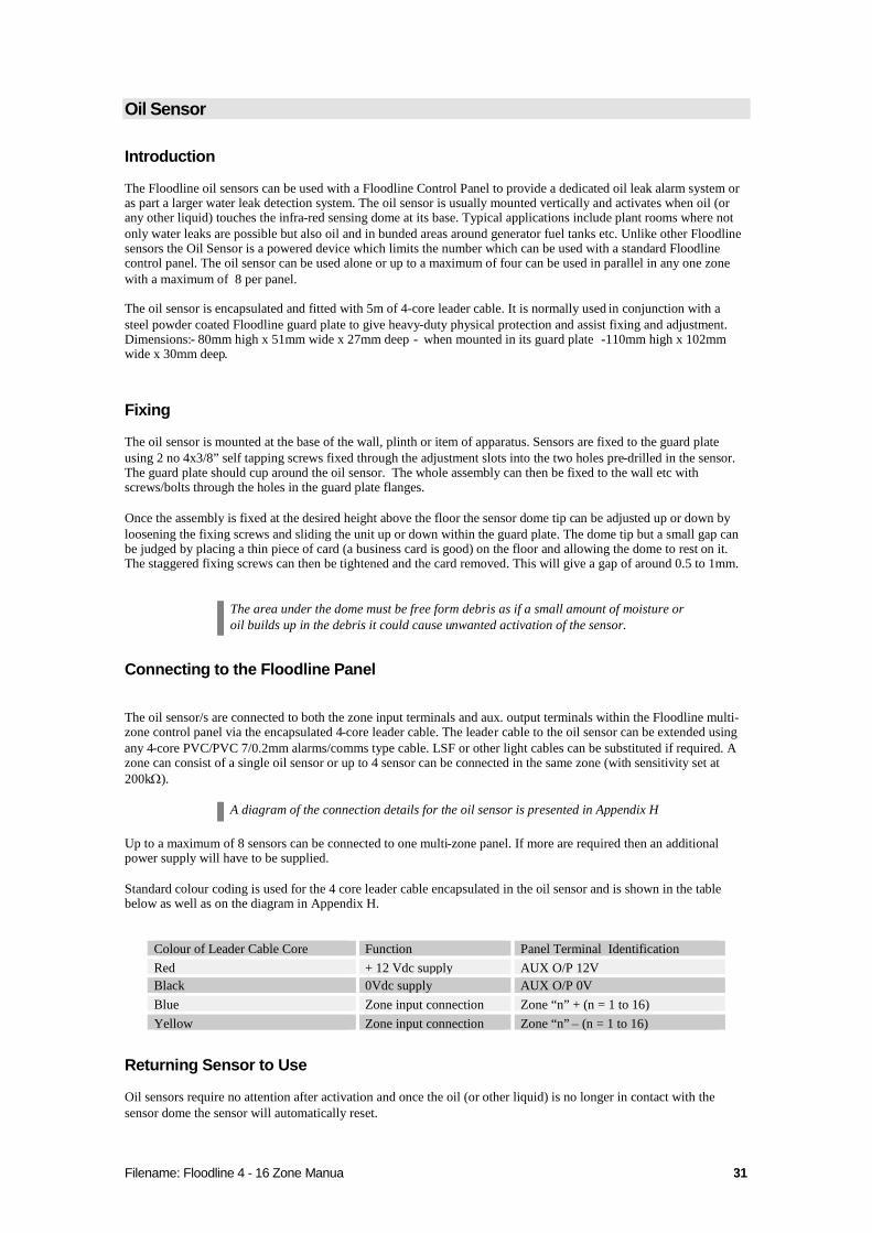
Standard colour coding is used for the 4 core leader cable encapsulated in the oil sensor and is shown in the tablebelow as well as on the diagram in Appendix H.
Colour of Leader Cable Core Function Panel Terminal IdentificationRed + 12 Vdc supply AUX O/P 12VBlack 0Vdc supply AUX O/P 0VBlue Zone input connection Zone “n” + (n = 1 to 16)Yellow Zone input connection Zone “n” – (n = 1 to 16)
Returning Sensor to Use
Oil sensors require no attention after activation and once the oil (or other liquid) is no longer in contact with thesensor dome the sensor will automatically reset.
Filename: Floodline 4 - 16 Zone Manua 32
Using other, non-liquid, types of sensors with the Floodline system
The flexibility of Floodline allows certain types of detection devices other than water/liquid sensors to be connectedto the system. These could be temperature or humidity sensors and some smoke detectors etc. There are certainrestrictions which must be observed such as not exceeding the available power and the ability to latch, or hold, a setof clean contacts for sufficient length of time for the Floodline Control Panel to recognise the alarm. Separateinstallation details will be issued as an addition to this manual should any “alien” devices be supplied as part of thesystem. Due consideration must also made to any regulations or standards which may pertain to other types ofsensing devices.
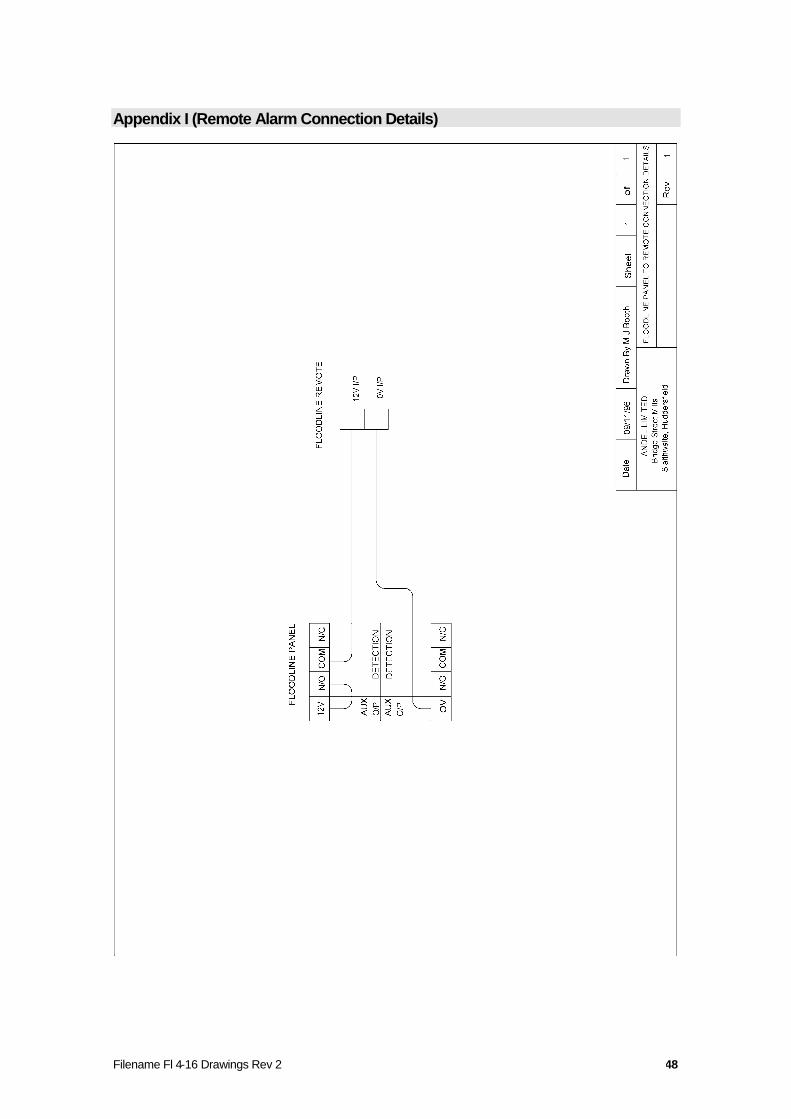
Remote Alarm
Introduction
Remote Alarm units are used to provide an alarm to a location distant from the control panel. This might be asecondary monitoring position, security office, reception desk etc The standard remote alarm is housed in a standardsurface mounted, white plastic, “ 2 gang” pattress box - dimensions 150mm wide x 85mm high x 45mm deep and hasthe following indicators and controls.
10mm red flashing LEDBuzzer -Key-switch – to disable the buzzer.
The unit receives a 12Vdc supply from the Floodline multi-zone panel when a leak (and/or system fault) alarm isactive. Special mounting or functions (i.e. delayed reactivation of audible alarm) can be offered as required.
Fixing
The remote alarm should be wall/surface mounted at a convenient level so that the visual alarms can be seen easilyand the key-switch can be accessed.
Connecting to Floodline Multi Zone Panel
The connection to the remote is via 2 core (minimum) PVC/PVC 7/0.2 alarm/comms type cable or similar and 2terminals are provided in the remote for connection to the Floodline multi-zone panel outputs.
A diagram of the connection details is found in Appendix I
Resetting The Remote
The remote alarm will reset when the main Floodline multi-zone panel is reset. It is not good practice to leave thekey-switch in the “buzzer disabled” position. The key should always be removed and this can only happen in the“buzzer enabled” position.

Filename: Floodline 4 - 16 Zone Manua 33
Troubleshooting
In any alarm condition please note carefully the affected zone number and whether thealarm is a leak or system fault.
On any occasion a LEAK alarm should be treated seriously and the affected zoneinspected immediately.
If there is only a minor leak, or undetectable drip (the causes of which are discussed below) then it may take sometime to verify that there has been a genuine leak and find its location - however – little or no damage will beoccurring and there will be less time pressure.
A major leak will be more immediately damaging but it will also be easy to verify and locate.
Power Problems
Important note:- isolate mains power before opening control panel and attempting tocheck/change fuses.
All fuses are carried on the main circuit board in the rear of the panel.
Mains indicator (green LED) not lit Battery indicator (red LED) lit - check mains power supply / external fuse /internal fuse FS1 (panel may be working but only on battery - rectify condition as soon as possible)
Low Battery indicator (red LED) lit (will be accompanied by intermittent bleeping)- battery may be discharged aftera long period without mains power or check internal battery charging fuse FS2.
DC Fuse indicator (green LED) not lit - panel will be dead. (Complete Power Failure relay will have de-activated.)Check main system fuse FS4.
Refer to manufacturer if fuse blows again - may be major circuit fault.
Remote Alarm/Auxiliary devices fail to function - check Auxiliary Power fuse.
Display Problems
All indicators go out, come back on in sequence then briefly flash together along with buzzer - repeats periodically –main system fuses FS4 for FS1 may be loose. - Isolate power, remove fuse and nip fuse carriers together to re-establish a firm grip. Check all other fuses at the same time.
Zone indicator(s) light and/or buzzer sounds but leak or system fault indicators do not light and panel will not reset -circuit failure, refer to manufacturer.
Leak or system fault indicator lights and/or buzzer sounds but Zone indicator(s) do not light and panel will not reset -circuit failure refer to manufacturer.
Filename Fl 4-16 Drawings Rev 2 34
“Spurious” Alarms or Alarms for No Apparent Reason
Almost without exception nearly all reported “spurious” alarms can be attributed to actual detection of water ordampness. The primary function of the system is to react to water (or other liquids) in whatever quantity or amount.
Sensors may be wrongly applied. The design of the installation and the choice of sensing devices should have takenaccount of site conditions and the importance placed by the end user on the sensitivity required. For example, atanked or bunded plant room may only require basic, low sensitivity, detection to warn of a flood whereas a computerroom may require comprehensive coverage using high sensitivity detection to warn of the earliest small leak. If highsensitivity detection is used in an area requiring only basic flood coverage then there will be a likely risk of unwantedalarms. The type of sensors may have to be changed.
Maintenance
User Maintenance - Day To Day
It is important to ensure that the complete power failure relay output is connected onwards to the BMS to provideconstant monitoring of the control panel’s operational status.
The correct functioning of the system can be verified on a day to day basis by observation of the two green indicatorsfor mains and dc fuse. Both indicators must be lit for correct operation.
Note must be taken of any system fault alarms or indicators and any other red indicators i.e. battery or low battery.The manufacturer or installer must be informed immediately of any of these latter events.
Filename Fl 4-16 Drawings Rev 2 35
Appendix A (Floodline Panel Base Board Layout)
Filename Fl 4-16 Drawings Rev 2 36
Appendix B (Single Zone Tape Connection Details)
Filename Fl 4-16 Drawings Rev 2 37
Appendix C (Multi –4-Zone Detection Cable Connection Details)
Filename Fl 4-16 Drawings Rev 2 38
Filename Fl 4-16 Drawings Rev 2 39
Appendix D (Multi –8-Zone Detection Cable Connection Details)
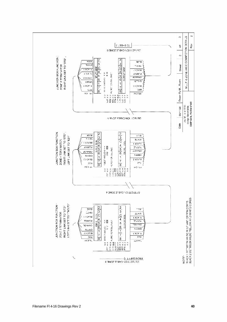
Filename Fl 4-16 Drawings Rev 2 40
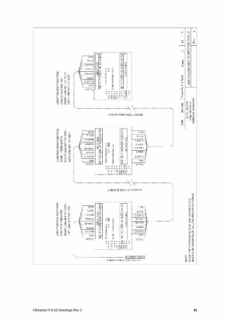
Filename Fl 4-16 Drawings Rev 2 41
Filename Fl 4-16 Drawings Rev 2 42
Appendix D-1 Multi-8-Zone Plug & Play
PATCH LEADER CABLE
Auto CouplerWhiteIn-flushOut-projects
Auto CouplerWhiteIn-flushOut-projects
Auto CouplerWhiteIn-flushOut-projects
Auto CouplerWhiteIn-flushOut-projects
Auto CouplerWhiteIn-flushOut-projects
Auto CouplerWhiteIn-flushOut-projects
Zone 8 M8-Detection CableZone 7 M8-Detection Cable
Zone 6 M8-Detection Cable
Zone 5 M8-Detection Cable
Zone 2 M8-Detection Cable
Zone 4 M8-Detection Cable
Zone 1 M8-Detection Cable
EOL (End Of Line)WhiteIn-FlushOut-None
Auto CouplerWhiteIn-flushOut-projects
SOL (Start Of Line)BlackIn,Out-FlushNot Polarised
EOL
ZONE
STRING REFERENCE
ZONE
FLOODLINE JUNCTION BOX
FLOODLINE JUNCTION BOX
ZONE
STRING REFERENCE
ZONE
SOL
CONNECTIONS TO ALARM PANEL Z0NE/SENSOR INPUT TERMINALSB
ROW
NZ1
+
BLA
CK
Z1-/C
OM
BLU
EZ
2+
WH
ITE
Z3+
PUR
PLE
Z4+
OR
AN
GE
Z5
+
GR
EEN
Z6
+
RED
Z7+
YEL
LOW
Z8
+
FLOODLINE JUNCTION BOX
ZONE
STRING REFERENCE
ZONE
Auto- CouplerFLOODLINE JUNCTION BOX
ZONE
STRING REFERENCE
ZONE
Auto- Coupler
FLOODLINE JUNCTION BOX
ZONE
STRING REFERENCE
ZONE
Auto- CouplerFLOODLINE JUNCTION BOX
ZONE
STRING REFERENCE
ZONE
Auto- CouplerFLOODLINE JUNCTION BOX
ZONE
STRING REFERENCE
ZONE
Auto- Coupler
FLOODLINE JUNCTION BOX
ZONE
STRING REFERENCE
ZONE
Auto- CouplerFLOODLINE JUNCTION BOX
ZONE
STRING REFERENCE
ZONE
Auto- Coupler
Filename Fl 4-16 Drawings Rev 2 43
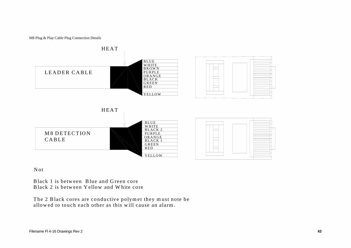
M8 Plug & Play Cable Plug Connection Details
B L U EW H IT EB R O W NPU R PL EO R A N G EB L A C KG R E ENR E D
Y E L L O W
L E A D E R C A B L E
H E A TSH R IN K
N oteB lack 1 is betw een B lue and G reen coreB lack 2 is betw een Y ellow and W hite core
T he 2 B lack cores are conductive polym er they m ust note beallow ed to touch each other as th is w ill cause an alarm .
H E A TSH R IN K
M 8 D E T E C T IO NC A B L E
Y E L L O W
B L A C K 1
PU R PL EB L A C K 2
G R E ENR E D
O R A N G E
W H IT EB L U E
Filename Fl 4-16 Drawings Rev 2 44
Appendix E (Point Sensor Connection Details)
Filename Fl 4-16 Drawings Rev 2 45
Appendix F (Flexi-pad Sensor Connection Details)
Filename Fl 4-16 Drawings Rev 2 46
Appendix G (Pipe-in-pipe Sensor Connection Details)
Filename Fl 4-16 Drawings Rev 2 47
Appendix H (Oil Sensor Connection Details)
Filename Fl 4-16 Drawings Rev 2 48
Appendix I (Remote Alarm Connection Details)