floor standing condensing boilers
TRANSCRIPT

EN 50
70
90
11
5 12
5 15
0 ULTRABOX
ULTRABOX 1000 ULTRABOX 1125
INSTALLATION AND USER MANUAL
FLOOR STANDING CONDENSING BOILERS
CONTENTS
1
1 Meanings of the Symbols and Safety 2 11 Meanings of the Symbols 2 12 General Warnings 2 13 Safety Instructions 2 14 Standards and Regulations 3 2 General 4 21 Purpose of Design 4 22 Introduction of the Product 4 23 Boiler Room and Ventilation 5 24 Warning Label 6 25 Packaging Label 6 26 Information Label 6 3 Technical Specifications 7 31 Dimensions 7 32 Contents 8 33 Technical Table 9 4 Installation Introductions 9 41 Installation 9 411 Packaging 9 412 Carrying 10 413 Mounting 11 414 Water Quality and Treatments 11 42 Hydraulic Connections 11 421 Expansion Tank 12 422 Safety Valve 12 423 Condensation Water Drain 12 424 Hydraulic Separator 12 425 Plate Heat Exchanger 13 426 Automatic Air Relief Valve 13 427 Deposit and Dirt Separator 13
428 Air Inlet Filter 14 429 Pump 14 43 Flue Connections 15 431 Flue Types 15 44 Electrical Connections 15 441 Wiring Diagram 16 442 Outdoor Temperature Sensor 21 5 Installation Examples 22 6 Operation 25 61 General 25 62 Display and Buttons 25 63 Operating Mode Selection 27 64 Programming 28 65 Main Functions 29 66 BMS ndash Boiler 0-10V Management 30 7 Parameters 31 71 End User Parameters 31 8 Error Fault Codes 32 9 Cascade 32 10 Combustion Adjustments 33 101 Emission Setpoints 33 102 Nominal Load Emission Settings 34 103 Minimum Load Emission Settings 34 104 Gas Pressure Switch 35 11 Maintenance 35 111 Maintenance Process 35 12 Energy Saving Recommendations 37 13 Disposal 37 14 Product Fiche 38 15 Trouble Shooting 39 16 Boiler Room Application Recommendations 40
IMPORTANT PLEASE READ INSTRUCTIONS BELOW CAREFULLY BEFORE THE INSTALLATION AND USAGE
1 THIS MANUAL IS AN INSEPARABLE PART OF THE BOILER AND HAS TO BE STORED TOGETHER WITH THE
BOILER IF THIS MANUAL DAMAGED OR LOST CONTACT GASSERO FOR A NEW COPY 2 THE INFORMATION AND INSTRUCTIONS THAT ARE SPECIFIED IN THIS USERS MANUAL APPLY ONLY FOR THE
BOILER MODELS SPECIFIED IN PAGE 3 3 THE INSTALLATION OF THIS BOILER MUST BE MADE IN ACCORDANCE WITH THE CE DIRECTIVES AND THE
LOCAL GAS ORGANIZATIONSrsquo INSTRUCTIONS BY AUTHORIZED SERVICES 4 SPECIFIED GAS MUST BE SUPPLIED BY AUTHORIZED GAS ORGANIZATIONS BEFORE THE COMMISSIONING OF
THE BOILER 5 COMMISSIONING OF THE BOILER MUST BE MADE BY GASSEROrsquoS AUTHORIZED SERVICES OTHERWISE
BOILER WARRANTY WILL BE CANCELLED 6 THE MANUFACTURER IS NOT THE RESPONSIBLE OF THE DAMAGE DUE TO WRONG OR IMPROPER
INSTALLATION OF THE BOILER 7 SOME PARTS OF THE PURCHASED BOILER COULD BE DIFFERENT THAN SHOWN BOILER PARTS IN THIS
MANUAL 8 MANUFACTURER (GASSERO) RESERVES THE RIGHT TO CHANGE THIS USERS GUIDE WITHOUT NOTICE 9 LIFE TIME OF THE BOILER IS 10 YEARS IF ALL OF THE INSTRUCTIONS FOLLOWED ACCORDING TO THIS USER
MANUAL 10 BOILER MAINTENANCE MUST BE MADE AT LEAST ONCE IN A YEAR
1 MEANINGS OF THE SYMBOLS AND SAFETY
11 MEANINGS OF THE SYMBOLS
The symbols which are used in this document and their meanings are as follows
WARNING Danger of material damage or damage to the environment
ELECTRICAL HAZARD Danger of death or serious injury due to electric shock
DANGER Actions that are certainly not to be done Material damage and severe personal damage may occur
Refers to the Information Recommendations to be considered by the user
12 GENERAL WARNINGS
Your boiler must be used in accordance with the instructions and purposes specified in the user manual The manufacturer cannot be held liable for damage to the people animals and property due to improper installation subsequent repairs and modifications
Boiler may not be used by persons with inadequate physical mental and perceptual capacity and without experience and knowledge
13 SAFETY INSTRUCTIONS
IF GAS SMELLS Do not open or close the power switches do not
touch the plugs or sockets Do not smoke Do not use your phone Close the gas valve immediately Ventilate the space by opening the doors and
windows Notify everyone in the building Call the emergency service of the gas distribution
company you are connected to Do not allow anyone to enter the boiler room until the emergency service arrives
If there is a sealing due to gas leakage do not disassemble the seal contact the gas distribution company to disassemble the seal after necessary repair
The smell of the waste gas formed after burning with natural gas may resemble each other Never use the boiler in the event of a leak in the waste gas system
2
3
IF WATER LEAKAGE OCCURS IN THE BOILER Switch off the electrical and water connections of
the boiler and notify the authorized service Condensation water formed after combustion is
corrosive and corrosive In case of leakage or leakage of this water inform the authorized service
IF ELECTRICAL LEAK OCCURS IN THE BOILER Never touch the boiler Lower the main switch on the board and notify the
authorized service Do not touch the pipes or the chimneys (there may
be a ground fault) Do not cut pull or bend the cables even if the
switch is lowered and the power cut off
DONrsquoT TOUCH THE BOILER WHEN YOUR HANDS ARE WET OR STEPPING ON A WET AREA
14 STANDARTS AND REGULATIONS
This boiler is manufactured in accordance with the following directives and standards EN 15502-1+A1 EN 15502-2-1+A1 (EU) 2016426 Gas Appliances Regulation (GAR) 201430EU Electromagnetic Compatibility (EMC) 201435EU Low Voltage Directive (LVD) 9242EEC Boiler Efficiency
These installation and maintenance instructions are prepared for the Floor Standing condensing boilers specified below
ULTRABOX 1000 ULTRABOX 1125
CE LABEL This boiler complies with the essential requirements of the relevant European directives The CE marking certifies that the products meet the essential requirements of the applicable regulations in accordance with the type of label Manufacturer can be consulted for the declaration of conformity
4
Gassero ULTRABOX Floor Standing Condensing Boilers with Premix Burners are designed for heating purposes only For hot water use the boiler must also be connected to the DHW tank Boiler can be used with in a cascade system or stand alone Maximum 16 boilers can work together in cascade systems Multi-purpose heating values can be achieved with cascade systems
Examples of stand alone and cascade systems are shown in the SAMPLE INSTALLATION DIAGRAMS section For cascade systems special cascade accessories such as mounting frame horizontal flue elements connection pipes between the boilers main gas pipe and hydraulic mixer (balance vessel) have been developed Such accessories make the cascade system easier to install with less effort For more detailed information on cascade systems please contact your dealer or manufacturer
This boiler is not suitable for industrial purposes The manufacturer cannot be held responsible for the problems caused by the usege except of the design purpose
22 INTRODUCTION OF THE PRODUCT
ULTRABOX is a condensing boiler which is modulated with a stainless steel heat exchanger and pre-mix burner for central heating and (optional) hot water production BASIC FEATURES OF SUPERBOX BOILERS 107 boiler efficiency through premix burner (See the technical
table) Through intelligent electronic control panel it has 13 safety
systems and 3 separate zone control options Room thermostat and outside temperature sensor provide
comfortable economic heating Besides the ease of operation via smart digital panel it provides
fault and error detection Web server provides remote control of the boiler Solar systems and pool temperature can be operated on the same
control panel
21 PURPOSE OF DESIGN
WARRANTY PERIOD AND LIFE TIME Warranty is 2 years from the date of invoice Service life of the boiler is 10 years (this period can be change according to the installation water quality and other environmental conditions)
CONSUMER RIGHTS Consumers can apply for complaints and appeals to consumer courts and consumer arbitration committees In case of defective goods a) Withdraw from the contract by stating that it is ready to returnthe product b) If all costs incurred do not incur excessive coststo request free repair of the product c) Requesting the replacement of the product with a non-defectiveproduct One of the rights can be used
5
ULTRABOX MODEL BOILERS ARE DESIGNED TO WORK ONLY WITH NATURAL GAS They cannot be used with LPG
23 BOILER ROOM AND VENTILATION
This boiler provides IPX4D electrical protection class Check that the place where the boiler is located complies with this protection class
Boilers must be placed 200 mm away from flammable materials with flammability class B C1 C2
Boilers must be placed 400 mm away from the easily flammable materials of the C3 class which can be ignited by themselves or by ignition sources
Never switch off the power supply of the boiler when the air temperature falls below 0degC against the risk of freezing Read the FROST PROTECTION section
ULTRABOX condensing boilers must be installed in spaces that have the necessary ventilation openings according to current standards and applicable regulations
Do not modify the ventilation openings ventilation ducts ventilation vents and do not block them after the commissioning
Never use the boiler in places where excessive amounts of dust are stored where barber shops corrosive explosive chemicals are stored or used
If the boiler receives the combustion air from the environment there should not be any low pressure due to other systems boilers in the boiler room
The boiler must be installed in accordance with the electrical voltages gas and water pressures specified in the technical table
Grounding of the electrical line is mandatory Never switch off the mains when the boiler is in operation
Such behavior may cause abnormal heat build-up and damage the heat exchanger and other units of the system
6
A B C D E F G H I
1000 105886 2400 11582 99889 1128 96786 12323 105886
1125 111642 2650 11582 106986 1128 103736 12323 111642
24 WARNING LABEL
WARNINGS Read the technical instructions and
user manual carefully before the commissioning
Commissioning must be made by an authorized Gassero service
The boiler must be located in a
location that is separate from the living quarters and only in accordance with the ventilation legislation
25 PACKAGING LABEL
26 INFORMATION LABEL
7
ULTRABOX 1000 - 1125
W 935 mm
L 2030 mm
H 1875 mm
AD Oslash200
M 4
R 4
G 2 frac12
F Oslash250
3 TECHNICAL SPECIFICATIONS
31 ULTRABOX DIMENSIONS
8
1 - Fan 2 - Gas Valve 3 - Control Panel 4 - Heat Exchanger 5 - İonisation Electrode 6 - Ignition Elekctrode 7 - Ignition Transformer 8 - Limit Thermostat 9 - Water Pressure Sensor 10 - Flow NTC Sensor 11 - Return NTC Sensor
12 - Automatic Airvent 13 - Flue Sensor 14 - Flue Outlet 15 - Syphon 16 - Water Outlet Connection 17 - Water Inlet Connection 18 - Gas Inlet 19 - Air Inlet 20 - Syphon Sensor 21 - Pressure Safety Valve
32 CONTENTS
9
min max min max
Compatible Chimney Types TipNominal Heat Input Qn kW 1158 9989 1158 10699
Nominal Heat Power Pn (80-60⁰C) kW 1129 9679 1129 10374
Nominal Heat Power Pn (50-30⁰C)10485791048579 kW 1232 10589 1232 11164
Working Pressure bar 08 6 08 6
Maximum Working Temparature ˚CLimit Temperature ˚CMinimum Efficiency Qmin (80-60⁰C) 9747 9689 9747 9696
Minimum Efficiency Qmin (50-30⁰C) 10719 10625 10719 10615
Partial Load Return 30degC Flue Gas Temperature (80-60) oC ˚C 6132 6181 6132 6301
Flue Gas Temperature (50-30) oC ˚C 3053 3122 3053 3361
CO2 Emissions (G20) 91 94 92 94
Modulation RatioNOx Class ClassNOx Value mgkWhFlue Gas Mass gsec 87 440 87 471
Water Flow (8060˚C) msup3h 4771 48585 4771 48585
Water Flow (5030˚C) msup3h 5069 46195 5069 49695
Hydraulic Loss kPaGas flow (80-60⁰C) msup3h 12033 10378 12033 111155
Gas flow (5030⁰C) msup3h 11965 109607 11965 109607
Maximum Gas Supply Pressure G20 mBarMinimum Gas Supply Pressure G20 mBarFlue Pressure PaFlue Gas Pipe Diameter mmNet Weight kg
17100
Oslash250897
196
4800
27
21
ULTRABOX 1125
9095
1074
B23-C43-C53-C63-C83
Oslash250897
ULTRABOX 1000
9095
10735
21
196
4100
27
17100
Ultrabox boilers are shipped on pallets as they are completely assembled tested and protected against damage by wooden frame and nylon PACKAGE INCLUDED bull User manual Warranty certificate bull Outdoor sensor bull Immersion type temperature sensor bull DHW sensor (optional) bull Air inlet filter (optional)
At any stage should not put anything else on the boiler stacking should not be done
When the boiler is unpacked check the contents of the package contact the dealer if there is any damage or missing components
4 INSTALLATION INTRODUCTIONS
41 INSTALLATION
411 PACKAGING
33 TECHNICAL TABLE
10
The boiler can be moved with a fork-lift or pallet truck as shown In such transports the boiler must be properly fixed and secured
The boiler must not be shaken or laid on its side during transport
The boiler can also be moved on its own wheels after being lowered
The wheels must always be secured and fixed when the transport is finished
During the transportation safety rules must be followed and care must be taken against injuries and crushing The manufacturer cannot be held liable for damage to people animals or property due to transportation faults
412 CARRYING
MINIMUM DISTANCES Gaps required for the installation service and maintenance are indicated left side bull The installation and chimney pipes must be connected in
such a way that they do not interfere with the service and maintenance operations
bull If the chimney connections are at the top of the boiler the detachability of the boilersrsquo top covers should be checked
bull The gas regulator must be installed at least 1 meter away from the boiler
In order to protect the boiler from water it is recommended to place the boiler on a base with 10cm high and suitable width for the boiler
413 MOUNTING
100 mm 100 mm
R E S E T
500 mm 500 mm500 mm 500 mm
11
414 WATER QUALITY AND TREATMENTS Paying attention to the following issues related to water quality will greatly reduce the problems that may arise during the life time of the boiler and ensure the continuity of the working efficiency Piping and installation components must be cleaned
before installation In old installations iron oxide sludge sediment and
similar deposits should be cleaned The water in the system should be analyzed in terms of
hardness pH iron content and conductivity
Total Hardness degd
pHIron
(Not Diluted)Conductivity
STAINLESS EXCHANGER 100 75-95 lt10ppm le2000microScm
ALUMINUM EXCHANGER 100 65-85 lt10ppm le2000microScm
Gassero Water Specification
If all or a part of the heating installation is to be operated by UNDERFLOOR HEATING SYSTEM PLATE HEAT EXCHANGER should be used and the system should be separated from each other as primary and secondary
Faults that may arise if the water conditions are not in accordance with the values specified in the table boiler will be considered out of warranty
DYNAMIC AND CHEMICAL WASHING FLUSHING In the newly established systems to aviod the possible substances in the installation (metal shavings some oils residues of construction wastes etc) flushing treatment is a mandatory Likewise it is a mandatory to apply the flushing treatment without water given to the boiler in conversion of older systems The methods of washing flushing are described in detail in the manual GASSERO DYNAMIC AND CHEMICAL WASHING FLUSHING Neutral-based non-acidic non-alkaline registered products can be used to clean the installation or keep the water conditions at desired levels You can get information from GASSERO for cleaner preservative or inhibitor type (stopper preventive) products or you can contact with SENTINEL or FERNOX companies
12
42 HYDRAULIC CONNECTIONS
According to the current legislation total heating capacity of the boiler or cascade system must be calculated to meet the buildings heat demand All necessary components must be installed and supplied correctly in the installation in a manner to perform their duty Protective and safety devices must be used in the heating system as described in the current legislation
In order to separate the boiler from the installation two ball valves should be placed on the supply and the return lines
421 EXPANSION TANK
ULTRABOX boilers do not have an expansion tank So the capacity of the expansion tank should be selected according to the capacity of the heating system and the static pressure
It is recommended to place the expansion tank on the turn of the central heating system
422 SAFETY VALVE
ULTRABOX boilers are equipped with a safety valve The hose of this safety valve must be connected to a drain Manufacturer cannot be held liable for damages caused by water flow into the boiler or on the ground when excessive pressure is generated in the heating installation
Safety valve must not be used as a means of draining water from the system
Draining water of the safety valve can be very hot Beware of scalding
423 CONDENSATION WATER DRAIN
Condensation water which is generated during to the combustion transfers to the water drain connection by the syphon and drain hose Condensation water is acidic and corrosive (approx 2 ph) So all of the connections which are made for condensation water must be made with PP type pipes Condensation water must be transferred to the drain with the shortest way possible For health and environmental reasons it mustnrsquot transfer such places near people animals and plants Condensation water must not be connected to rain drain
systems The condensate drain line must have a slope of at least 3 A neutralization tank should be used for condensate water
occurring in systems with a total power of 200 kW and above It is mandatory to comply with the relevant local regulations for
the discharge of condensate water
Syphon Sensor
423 YOĞUŞMA SUYU TAHLİYESİ
Yanma sırasında kazanda oluşan yoğuşma suyu bir sifon ve drenaj hortumu vasıtası ile atık su bağlantısına iletilir Yoğuşma suyu asidik ve koroziftir( Yaklaşık 2 ph ) Dolayısıyla bağlantıların tamamı PP plastik boru ile yapılmalıdır Yoğuşma suyu muumlmkuumln olan en kısa yoldan atık su
giderine verilmelidir Sağlık ve ccedilevresel nedenlerle insanların hayvanların ve bitkilerin bulunduğu ortamlara zeminlere verilmemelidir
Yoğuşma suyu yağmur tahliye sistemlerine bağlanmamalıdır
Yoğuşma suyunun korozif etkisi nedeniyle metal malzemeden imal edilmiş borular kullanılamaz
Yoğuşma suyu tahliye hattı en az 3 eğime sahip olmalıdır
Toplamda 200 kW ve uumlzeri guumlce sahip sistemlerde meydana gelen yoğuşma suları iccedilin noumltralizasyon tankı kullanılmalıdır
Noumltralizasyon kutusu dondan ve diğer atmosferik şartlardan etkilenmeyecek bir yere konumlandırılmalıdır (+1 ˚C ile +40 ˚C arası)
424 DENGE KABI
Birden fazla pompanın veveya ısıtma devresinin kullanıldığı sistemlerde basınccedil farklılıklarını dengelemek kazan giriş ve ccedilıkış su sıcaklıkları arasındaki aşırı farkı ortadan kaldırmak ve kazanda oluşacak ısıl gerilmeleri oumlnlemek iccedilin kullanılırlar bull Boyutları giriş ve ccedilıkış mesafeleri doğru seccedililmelidir bull Uumlzerlerine koyulacak bir sensoumlr yardımıyla sistemin genel
sıcaklığı denge kabı uumlzerinden tespit edilir bull Denge kabı uumlzerinde mutlaka otomatik hava alma purjoumlruuml
olmalıdır
Sistemdeki suyun ccedilok kirli kireccedilli veya korozif olduğu durumlarda DENGE KABI yerine PLAKALI EŞANJOumlR kullanılmalıdır
13
14
425 PLATE HEAT EXCHANGER
Plate heat exchangers are hydraulic equipments that separates the boiler and the installation (primary and secondary zones) Unlike the hydraulic separator circulating water in the plate heat exchanger never interfere with the water goes through the boiler and the water goes through the installation Only heat transfer occurs here Preferred for many purposes If the water in the system is very dirty chalky or corrosive If the working pressure of the system exceeds the working
pressure of the boiler If a part or all of the system is required to operate with lower
temperature values (eg underfloor heating systems)
The plate heat exchanger must be used in the following cases and the system must be separated into primary and secondary -Heating systems which are consist of partly of fully floor heating -Used older systems -Systems that are dirty corrosive bacterial and calcareous water
Periodic inspection and maintenance of the plate heat exchanger is highly important for the efficiency of the system
426 AUTOMATIC AIR RELIEF VALVE
ULTRABOX boilers have an automatic relief valve for the evacuation of the air accumulated in the heat exchanger However for the evacuation of the air that may occur in the installation it is necessary to place one or more automatic air relief valves in the appropriate places of the installation Local regulations must be followed in this regard
To remove the dirt and particles form the water a strainer or deposit and dirt separator must be placed on the return line of the boiler When the dirt particles and similar deposits in the system water are not cleaned The efficiency of the system decreases Installation equipments (pumps valves plate heat exchanger
etc) may be damaged due to overheating A boiler damage may occur due to heat exchanger clogging
Manufacturer cannot be held liable for damages that may occur in such cases
Strainers or deposit and dirt sepertors on the system should be checked frequently and cleaned if necessary
427 DEPOSIT AND DIRT SEPARATOR
429 POMPA
15
428 AIR INLET FILTER (OPTIONAL)
If ULTRABOX boilers will be used in to a dirty air environment they must be supported with the air inlet filters This optional filter must be checked regularly When the air inlet filter becomes dirty Emission values would be deteriorated and efficient
combustion wouldnrsquot be achieved The accumulation of soot occurs in the heat exchanger Loud ignition and combustion occurs Overheating leakage and deformation would be observed
in the flue system
Manufacturer cannot be held liable for damages caused by dirty combustion air Donrsquot block the air filter partially or totally
min max mwc
ULTRABOX 1000 5069 46195 6
ULTRABOX 1125 5069 49695 6
WATER FLOW (msup3h)Pumps arenrsquot included in ULTRABOX model boilers The primary pumps which are determined according to the hydraulic pressure losses of the boiler are offered by Gassero as an option If a different primary pump is to be used pump must be selected in accordance with the values given in the table on the left
The use of an unsuitable primary pump can result an uneconomic uncomfortable operation and damage to your boiler and your installation The manufacturer is not liable for damages that may arise from such situations
The primary pump must be mounted on the return line (See INSTALLATION EXAMPLES)
Installation of primary and secondary pumps to the installation and wiring of the power supply cables are in responsibility of the installation mechanical electrical teams
The power supplies of all primary and secondary pumps are provided via the boilersrsquo electrical panel The switch-on signal to the contactors in the electrical panel is sent by the signal cable from the terminals Q1-Q2-Q3 located on the back of the boilers (See ELECTRICAL CONNECTION EXAMPLES)
220 V PUMP CONNECTION EXAMPLE 400 V PUMP CONNECTION EXAMPLE
16
Flue and chimney connections must be carried out in accordance with applicable regulations and relevant standards Materials which are used for the flue and chimney must be resistant to the temperature corrosive effect of condensation water and mechanical stresses and must be gas-tight
Never use the new boiler with the flues which are used for solidliquid fuel boilers or shunt chimneys
Chimney system and the condensation drainage systems connected to it should be checked once a year and cleaned if necessary
431 FLUE TYPES
43 FLUE CONNECTIONS
B23 ndash It is a flue system that takes the combustion air from the environment and throws flue gas to the outside
C43ndash It is a flue system that takes the combustion air from the outside and throws flue gas to the outside with seperate flue pipes
C83ndash It is a flue system which takes the combustion air from the outside with horizontal flue pipes and throws flue gas to the self contained (negative pressure) chimney
C53ndash It is a flue system that takes the combustion air from the outside and throws flue gas to the outside with the vertical and horizontal concentric flue pipe system
The flue types that are valid in Ultrabox model boilers are given below
17
44 ELECTRICAL CONNECTIONS
For the operation of the boiler a grounded electrical supply 230 VAC 50Hz is required (tolerance must be between -15 ve +10 )
Electric supply of the boiler must be cut off via a fuse during the maintenance Electrical operations must be made by authorized technical personal in accordance with regulations and
standards Cables should not be passed close to hot surfaces (such as hot water pipes) L (phase) N(neutral) and grounding connections must be made properly All cables must be fitted with a ferrule
The manufacturer cannot be held liable for damages caused by negligence or incorrect operation in the earthing of the boiler
441 WIRING DIAGRAM
CABLE SECTION
CONNECTION EXPLANATION
BROWN
YELLOWGREEN
BLUE
BROWN
YELLOWGREEN
BLUE
BROWN
YELLOWGREEN
BLUE
BROWN
YELLOWGREEN
BLUE
Using for PRIMARY CIRCULATION PUMP 2 X 15 cable has to be connected to PRIMARY CIRCULATION PUMP contactors phase terminal on the electrical panel Electrical panel connections will be made by the installation services Boiler connections from the electrical panel will be made by authorized Gassero service
Using for DHW pump control via Master boiler 2 X 15 cable has to be connected to DHW PUMP contactors phase terminal on the electrical panel Electrical panel connections will be made by the installation services Boiler connections from the electrical panel will be made by authorized Gassero service
3 X 15Q2 SYSTEM PUMP
CABLE
Using for system pump control via master boiler 2 X 15 cable has to be connected to SYSTEM PUMP contactors phase terminal on the electrical panel Electrical panel connections will be made by the installation services Boiler connections from the electrical panel will be made by authorized Gassero service
3 X 15Q3 DHW PUMP
CABLE
BOILER SIDE CONNECTIONS
3 X 15 SUPPLY CABLEBROWN= PHASE BLUE = NEUTRAL YELLOW = GROUND has to be connected to a 6A fuse
3 X 15 Q1 BOILER PUMP
CABLE SECTION
PICTURE CONNETION EXPLANATION
RED
REDBLACK
BLACK
BLACKWHITE
YELLOW
YELLOWBLACK
BROWN
BROWNBLACK
BLUE
BLUEBLACK
PURPLE
GREY
YELLOW
GREEN
PUMP PWM CONTROL
0 - 10 V
It connects to frequency controlled (modulating) primary pumps 0-10 terminal It controls the modulation of the pump
2x15
Immersion Type Cascade
Temperature Sensor
Cascade Module
0 - 10 V INPUT
Room Thermostat
Outside Sensor
Immersion Type DHW
Temperature Sensor
Connects to the supply collector the hydraulic seperator or the plate heat exchanger Measures the flow temperature It operates from 0 deg C to 95 deg C (with + 05 -05 deg C tolerance)
It provides communication between boilers in cascade systems 16 boilers can be communicate with each other
Used for to connect Remote Control Systems
Room comfort setting and operation mode can be adjusted Maximum 50 m length connection is possible
Boiler or cascade system operates according to the outside air temperature Maximum 50 m length connection is possible It operates in the range of -50 deg C to 70 deg C (with + 1 -1 tolerance)
Measures the DHW tank temperature It can operate from 0 deg C to 95 deg C (with + 05 -05 deg C tolerance)
BOILER SIDE CONNECTIONS
2x15
2x15
2x15
2x15
2x15
2x15
18
19
20
21
442 OUTSIDE TEMPERATURE SENSOR
When an outside temperature sensor installed boiler will adjust supply temperature according to the outside temperature in order to provide energy saving without compromise the comfort Outside Temperature Sensor must be Installed - north or north-west direction of outside of the building - at a height of minimum 25m from the ground - not exposed to direct sunlight - straight side of the wall - in a place away from doors windows chimneys and
vents Open the sensor housing cover by turning it
counterclockwise to access the sensor connection terminal and the wall fixing holes
Mark the fixing points on the wall and drill the wall using the storage box as a template
Secure the box to the wall using the two anchors provided
Connect the two-wire cable from the boiler to the terminal box (nonpolar)
Tighten the nut in the housing box to ensure water-tightness of the cable connection
Maximum length between the control panel and the outside temperature sensor is 50 meters
Sensor cable has to be used as a single cable as possible Aware of multiple additions as far as possible
H
H2
1
NN-W
min
25
m
22
5 INSTALLATION EXAMPLES
MEC
HA
NIC
AL
SCH
EME
(WIT
H H
YDR
AU
LIC
SEP
ERAT
OR
)In
stal
latio
n of
2 F
LOO
R S
TAN
DIN
G C
ON
DEN
SIN
G B
OIL
ERS
in c
asca
de w
ith 1
RAD
IATO
R C
IRC
UIT
- Wat
er S
ofte
ner U
nit m
ust b
e us
ed in
the
syst
em
- A n
eutra
lizat
ion
tank
sho
uld
be u
sed
for c
onde
nsat
e w
ater
occ
urrin
g in
sys
tem
s w
ith a
tota
l pow
er o
f 200
kW
and
abo
ve
Pum
p
Expa
nsio
nTa
nk
Safe
ty V
alve
Air S
eper
ator
Dep
osit
and
Dirt
Sep
erat
or
Out
door
Sen
sor
Wat
er S
ofte
ner
UN
it
Tem
pera
ture
Se
nsor
Glo
be V
alve
Term
omet
erM
anom
eter
Non
-Ret
urn
Valv
e
Hyd
raul
ic
Sepe
rato
r
Gas
Reg
ulat
or
Stra
iner
Neu
traliz
atio
n Ta
nk
WAT
ER S
OFT
ENER
U
NIT
HYD
RAU
LIC
SEP
ERAT
OR
RAD
IATO
R C
IRC
UIT
Air
Rel
ief V
alve
23
M
MEC
HA
NIC
AL
SCH
EME
(WIT
H H
YDR
AU
LIC
SEP
ERAT
OR
)In
stal
latio
n of
2 F
LOO
R S
TAN
DIN
G C
ON
DEN
SIN
G B
OIL
ERS
in c
asca
de w
ith 1
RAD
IATO
R C
IRC
UIT
+ 1
DH
W C
IRC
UIT
RAD
IATO
R
CIR
CU
ITD
HW
C
IRC
UIT
HYD
RAU
LIC
SEPE
RAT
OR
WAT
ER S
OFT
ENER
U
NIT
- Wat
er S
ofte
ner U
nit m
ust b
e us
ed in
the
syst
em
- A n
eutra
lizat
ion
tank
sho
uld
be u
sed
for c
onde
nsat
e w
ater
occ
urrin
g in
sys
tem
s w
ith a
tota
l pow
er o
f 200
kW
and
abo
ve
Pum
p
Expa
nsio
nTa
nkSa
fety
Val
ve
Air S
eper
ator
Dep
osit
and
Dirt
Sep
erat
or
Out
door
Sen
sor
Wat
er S
ofte
ner
UN
it
Tem
pera
ture
Se
nsor
Glo
be V
alve
Term
omet
erM
anom
eter
Non
-Ret
urn
Valv
e
Hyd
raul
ic
Sepe
rato
r
Gas
Reg
ulat
or
Stra
iner
Neu
traliz
atio
n Ta
nk
Air
Rel
ief V
alve
MMM
M 3-W
ay
Mot
oriz
ed V
alve
24
PLAT
E H
EAT
EXC
HAN
GER
MMMM
Pum
p
Expa
nsio
nTa
nkSa
fety
Val
ve
Air S
eper
ator
Dep
osit
and
Dirt
Sep
erat
or
Out
door
Sen
sor
Wat
er S
ofte
ner
UN
it
Tem
pera
ture
Se
nsor
Glo
be V
alve
Term
omet
erM
anom
eter
Non
-Ret
urn
Valv
eG
as R
egul
ator
Stra
iner
Neu
traliz
atio
n Ta
nk
Air
Rel
ief V
alve
M 3-W
ay
Mot
oriz
ed V
alve
Plat
e H
eat
Exch
ange
r
RAD
IATO
R
CIR
CU
ITD
HW
C
IRC
UIT
FLO
OR
HEA
TİN
GC
IRC
UIT
MEC
HA
NIC
AL
SCH
EME
(WIT
H P
LATE
HEA
T EX
CH
AN
GER
)In
stal
latio
n of
2 F
LOO
R S
TAN
DIN
G C
ON
DEN
SIN
G B
OIL
ERS
in c
asca
de w
ith 1
FLO
OR
HEA
TIN
G C
IRC
UIT
+ 1
RAD
IATO
R C
IRC
UIT
+ 1
DH
W C
IRC
UIT
WAT
ER S
OFT
ENER
U
NIT
- Wat
er S
ofte
ner U
nit m
ust b
e us
ed in
the
syst
em
- A n
eutra
lizat
ion
tank
sho
uld
be u
sed
for c
onde
nsat
e w
ater
occ
urrin
g in
sys
tem
s w
ith a
tota
l pow
er o
f 200
kW
and
abo
ve
- Pla
te H
eat E
xcha
nger
mus
t be
used
in F
LOO
R H
EATI
NG
SYS
TEM
S
25
6 OPERATION
61 GENERAL
ULTRABOX boilers Controls 3 heating zones It could be increase with
placing additional zone modules Calculates exact temperatures for each zone via sensors
and outside temperature sensor Saves and display the fault and error history Integrated with cascade control system to work with
multiple boilers according to heat demand equally Integrated with frost and legionella protection systems Can be control via internet or BMS systems with
addtional modules
All comissioning installation maintenance etc must be performed by authorized personnel
Improper interventions may cause loss of life and property increased fuel consumption and deterioration in safe and comfortable operation
Manufacturer cannot be held liable for any problems caused by incorrect adjustments and interventions
Display symbols Comfort setting for heating
Reduced heating setting for heating
Frost protection setting for heating
In progress ndash Please wait
Change the battery
Burner on
Info menuuml activated
Programming menu activated
ECO funtion activated
Holiday function activated
Heating referance
Maintenance mode
Error
62 DISPLAY AND BUTTONS
XxxxxxxxxxxxxxxxxxxxxxxxxXxxxxxxxxxxxxxxxxxxxxxxxx
Xxxxxxxxxxxxxxxxxxxxxxxxx
A CB D E
H
G
F
I
J
26
DISPLAY (G) Backlight display automatically turn off without operation Push any button to turn it on again Screen displays information settings below - Operation modes - Temperatures - Parameters - Faults errors
HEATING MODE BUTTON (H) Used for to choose and select 4 different heating modes
DHW MODE BUTTON (I) Used for to turn on or off the DHW mode
NAVIGATION AND ADJUSTMENT KNOB (B) Changes comfort temperature setting Additionally it also used for increase decrease temperatures choose and select sub menus Change the settings
OK BUTTON (C) Used for to apply selected value or setting In the parameters section this button is used for the further menu options HEATING MODE SELECTION Press the appropriate button to select between different heating modes
CANCEL BUTTON ndash ESC (A) Used for to cancel the settings and return to upper menu section
MANUAL CONTROL BUTTON (D) Used for to run to boiler manually During the manual operation all pumps will be ran but mixing valves wouldnrsquot be operated Burner temperature will be held at adjusted temperature while the commissioning Pushing to this button more than 3sec will be opareted the air relief function During this function burner will held into standby mode pumps will be energised periodically mixing valves ran into middle position This function will be turned off automatically after the cycle
FLUE FUNCTION (E) Used for flue gas emission measuring During this function boiler will be operated according to maximum adjusted temperature until it reach the exact value Then this function will be turned off automatically
INFO BUTTON (F) Used for the display boiler information such as temperatures operating modes error codes etc
RESET BUTTON (J) Used for to reset any fault and error which caused to stop the boiler
Auto Boiler will be operated according to adjusted time program Comfort Temperature Boiler will be operated according to adjusted comfort temperature permanently Reduced Temperature Boiler will be operated according to adjusted reduced temperature permanently Standby Heating will be turned off but frost protection still activated unless the power supply is disconnected
DHW MODE SEELECTION When the corresponding button is used the boiler is switched on to operate synchronously with the units that produce hot water (DHW tank plate heat exchanger etc) This function can be switched off or on Pressing the button once will be activate the boiler to heat the DHW tank Pressing it again disables DHW tank heating Pressing the button for 3 seconds activates the Quick Water Heating Mode for faster hot water production
27
28
ADJUSTING THE ROOM TEMPERATURE The temperature (comfort value) of the room which is heated by the heating circuit-1 is set by the Navigation Button The boiler will be activated and keep the room temperature constant to the set temperature To adjust Turn the Navigation Knob in any direction Set the desired room temperature and press OK (Factory setting is 20degC)
ADJUSTING OTHER HEATING CIRCUITS If there is more than one heating circuit in the system the comfort temperature can be set separately for each circuit To adjust Press OK Turn the Navigation Knob to select Heating circuit-2 and press OK Adjust the desired room temperature and press OK Press ESC button to return upper menu and adjust other heating circuits
REDUCED TEMPERATURE A temperature limit for the room temperature When the room temperature falls below the set temperature the boiler will be activated and keep the room temperature constant (Factory setting is 10 degC) To adjust Press OK Turn the Navigation Knob and select Heating circuit-1 by pressing OK Turn the navigation Knob and select Heating circuit-1 Reduced setting temperature by pressing OK Adjust the desired Reduced setting temperature and press OK Press ESC button to return upper menu and adjust other heating circuits
63 OPERATING MODE SELECTION
FROST PROTECTION It will be activated when the temperature of the water in the boiler falls below 4degC and activates the primary circulation pump In order for the frost protection mode to be active boilers electrical switch must be switched on and the system water must be full
64 PROGRAMMING
If there is no other control panel (cascade control unit etc) in the system all personalized settings parameters fault resets will be made via the control panel Eg Date and time adjustment Push OK button Select laquoTime of day and dateraquo then push OK button again Push OK button for adjusment Push OK button to adjust hour and minute settings Turn the adjusment knob one click and set mounth and day with pushing OK button Push OK button to adjust the year as a final step Push ESC button to return the home secreen
Frost Protection function is valid only for boiler can not protect the installation
29
65 MAIN FUNCTIONS
Button Action Procedure Display Function
Actuate rotary knob leftright Comfort setpoint with blinking temperatureTurn rotary knob Confirm with OK button Blinking temperature in 05 degC steps from 10 to 30 degCor wait 5 sec Comfort setpoint savedor press Comfort setpoint cancelled
- after 3 sec Main menu appearsSet room temperature for Zone 2 independent from zone 1 Choose heating zonezone 1 or zone 2 Actuate rotary knob leftright Heating zone is chosen
Confirm with OK button Blinking temperature in 05 degC steps from 10 to 30 degCActuate rotary knob leftrightConfirm with OK buttonor wait 5 sec Comfort setpoint savedor press Comfort setpoint cancelled
- after 3 sec Main menu appearsSwitch on off DHW operation Press button DHW mode on off
(see indication below DHW symbol)- On DHW mode by time programm- Off no DHW operation- Safety functions activated
Factory setting Automatic mode on with- Heating by time programm- Temperature setpoint by heating programm- Safety functions activated- SummerWinter automatic switching activated- ECO-functions activated(see indication below operation symbol)
Press button 1x Continuous COMFORT heating on with- Heating without time programm by comfort setpoint- Safety functions activated
Press button 1x again Continuous REDUCED heating on with- Heating without time programm by reduced setpoint- Safety functions activated- SummerWinter automatic switching activated- ECO-functions activated
Press button 1x again Safety mode on with- Heating off- Temperature by frost protection- Safety functions activated
Controller Stop Mode Press button gt 3 sec 304 Controller Stopp mode insert setpointPress button gt 3 sec again after 3 sec Main menu appearsPress button 1x INFO Segment displayedPress button 1x again - Status Boiler - room temperaturePress button 1x again - room temperature minimumhellip - Status DHW - room temperature maximum
- Status zone 1 - outside temperatureInfo display - Status zone 2 - outside temperature minimum
Time Date - DHW temperature 1- Error indication - Boiler temperature- Maintenance indication - Flow temperature(Info display depends on configuration)
Press button 1x Back to main menu INFO Segment disappearsOperation by manual Press button 1x Manual mode on (spanner symbol appears)setpoint - Haeting by fixed setpointChange factory setting Press button (factory setting = 60 degC)boiler temperature Press button 301 Manual mode insert setpoint
Turn rotary knob -+ blinking temperaturePress button set valuePress button Status boilerPress button Manual mode off (spanner symbol disappears)
Deaeration Press button gt 3 sec 312 Deaeration onPress button gt 3 sec again Deaeration off
Activate chimney sweeper Press button (lt 3 sec) Chimney sweeper mode onmode Press button again (lt 3 sec) Chimney sweeper mode off
Temporary reduction of Press button Heating by reduced setpointreduced temperature on QAA75 Press button again Heating by comfort setpointReset button Press button (lt 3 sec) Boiler manually blocked no release
Press button again gt 3 sec Boiler released Alarm symbol disappearsRESET
Change heating operationmode
Zone 1 and zone 2
Set room temperature
30
66 BMS ndash BOILER 0-10V MANAGEMENT
31
1) H3 output could use for 0-10V management After cable connection 5960 parameter should set lsquoConsumer Request CC1 10Vrsquo from configuration menu 2) 5963-64-65-66 parameter should set for heat and value assignment 3) Heating Circuit 5710 and 5715 parameter should set lsquoOFFrsquo from configuration menu 4) DHW (Domestic Hot Water) Circuit sensor should be cancelled from boiler
Due to incorrect adjustments energy saving operation may not be observed and the whole system or some parts of the units may be damaged
Manufacturer cannot be held liable for malfunctions and damages resulting from incorrect settings made by unauthorized persons
71 END USER PARAMETERS
7 PARAMETERS
Parameters of ULTRABOX boilers are divided into 4 groups according to their level END USER PARAMETERS COMMISSIONING ENGINEER OEM
32
MENU LINE NO OPERATING LINE UNIT MIN MAX FACTORY SETTINGS1 Hours Minutes hhmm 0000 2359 ----2 Day Month ttMM 101 3112 ----3 Year jjjj 2004 2099 ----
29 Birimler - ˚C bar500 Preselection - Mo-Su501 Mo-Su 1 Phase On hhmm 0000 2400 0600502 Mo-Su 1 Phase Off hhmm 0000 2400 2200503 Mo-Su 2 Phase On hhmm 0000 2400 ----504 Mo-Su 2 Phase Off hhmm 0000 2400 ----505 Mo-Su 3 Phase On hhmm 0000 2400 ----506 Mo-Su 3 Phase Off hhmm 0000 2400 ----516 Default values - No 520 Preselection - Mo-Su521 Mo-Su 1 Phase On hhmm 0000 2400 0600522 Mo-Su 1 Phase Off hhmm 0000 2400 2200523 Mo-Su 2 Phase On hhmm 0000 2400 ----524 Mo-Su 2 Phase Off hhmm 0000 2400 ----525 Mo-Su 3 Phase On hhmm 0000 2400 ----526 Mo-Su 3 Phase Off hhmm 0000 2400 ----536 Default values - No 560 Preselection - Mo-Su561 Mo-Su 1 Phase On hhmm 0000 2400 0600562 Mo-Su 1 Phase Off hhmm 0000 2400 2200563 Mo-Su 2 Phase On hhmm 0000 2400 ----564 Mo-Su 2 Phase Off hhmm 0000 2400 ----565 Mo-Su 3 Phase On hhmm 0000 2400 ----566 Mo-Su 3 Phase Off hhmm 0000 2400 ----576 Default values - No 641 Preselection - Period 1642 Period Start Day Month ttMM 0101 3112 ----643 Periode End Day Month ttMM 0101 3112 ----648 Operating level - Frost protection651 Preselection - Period 1652 Period Start Day Month ttMM 0101 3112 ----653 Periode End Day Month ttMM 0101 3112 ----658 Operating level - Frost protection661 Preselection - Period 1662 Period Start Day Month ttMM 0101 3112 ----663 Periode End Day Month ttMM 0101 3112 ----668 Operating level - Frost protection710 Comfort setpoint degC Value from Line no 712 35 20712 Reduced setpoint degC 4 Value from Line no 710 16714 Frost protection setpoint degC 4 Value from Line no 712 10720 Heating curve slope - 01 4 15730 Summerwinter heating limit degC ---8 30 20
1010 Comfort setpoint degC Value from Line no 1012 35 201012 Reduced setpoint degC 4 Value from Line no 1010 161014 Frost protection setpoint degC 4 Value from Line no 1012 41020 Heating curve slope - 01 4 151030 Summerwinter heating limit degC ---8 30 201600 DHW operating mode - On1610 Nominal setpoint ˚C Value from Line no 1612 Value from Line no 1614 551612 Reduced setpoint ˚C 8 Value from Line no 1610 402055 Pool setpoint solar heating degC 8 80 262056 Pool sepoint boiler heating degC 8 80 22
Boiler 2214 Setpoint manual control degC 10 90 806705 SW Diagnose Code - - - Indication only6706 Burner ctrl phase lockout pos - - - Indication only
Time program HC 2 (When activated)
Mo-Su Mo-Fr Sa-Su MoTuWeThFrSaSu
Yes No
Time of day and date
Operator section 20 Language - English Deutsch Francais Italiano Dansk Nederlands Espantildeol Česky Slovenskyacute Tuumlrkccedile
English
˚C bar˚F PSITime program HC 1
Mo-Su Mo-Fr Sa-Su MoTuWeThFrSaSu
Yes No
Holidays HC1
Period 1 2 3 4 5 6 7 8
Frost protection Reduced
Time program 4DHW Mo-Su Mo-Fr Sa-Su MoTuWeThFrSaSu
Yes No
Fault
Holidays HC2 (When activated)
Period 1 2 3 4 5 6 7 8
Frost protection ReducedHolidays HC3 (When activated)
Period 1 2 3 4 5 6 7 8
Frost protection ReducedHC1
HC2(When activated)
DHW On Off Eco
Swimming pool
8 ERROR FAULT CODES
ULTRABOX boilers are equipped with a fault diagnosis system When a malfunction code is displayed on both the Master and Slave boilers the red light on the bottom of the control panel flashes with the no flame sign Malfunction codes are given below
Error Code Error Description Error
Code Error Description Error Code Error Description
10 Outside temperature sensor error 130 Flue gas temperature limit exceeded 328 146 Mixing group same function20 Boiler temperature 1 sensor error 132 GP or LP error 329 146 Extension modulemixing group same 26 Common flow temperature sensor error 133 No flame during safety time 330 Sensor BX1 no function28 Flue gas temperature sensor error 146 Configuration error collective message 331 Sensor BX2 no function30 Flow temperature 1 sensor error 151 Internal error 332 Sensor BX3 no function38 Flow temperature primary controller sensor error 152 Parameterization error 333 Sensor BX4 no function40 Return temperature 1 sensor error 153 Unit manually locked 335 Sensor BX21 no function (EM1 EM2 or EM3)46 Return temperature cascade sensor error 160 Fan error 336 Sensor BX22 no function (EM1 EM2 or EM3)47 Common return temperature sensor error 162 LP error does not close 339 Collector pump Q5 not available50 DHW temperature 1 sensor error 164 Error heating circuit flow switch 340 Collector pump Q16 not available52 DHW temperature 2 sensor error 166 LP error does not open 341 Solar Collector sensor B6 not available54 DHW primary controller sensor error 169 Sitherm Pro system error 342 DHW sensor B31 not available57 DHW circulation temperature sensor error 170 Error water pressure sensor primary side 343 Solar integration not available60 Room temperature 1 sensor error 171 Alarm contact H1 or H4 active 344 Solar controlling element buffer K8 not available65 Room temperature 2 sensor error 172 Alarm contact H2 (EM1 EM2 or EM3) or H5 active 345 Solar ctrl element swimming pool K18 not 70 Buffer storage tank temperature 1 sensor error 173 Alarm contact H6 active 346 Solid fuel boiler pump Q10 not available71 Buffer storage tank temperature 2 sensor error 174 Alarm contact H3 or H7 active 347 Solid fuel boiler comparison sensor not available72 Buffer storage tank temperature 3 sensor error 176 Water pressure 2 too high 348 Solid fuel boiler address error73 Collector temperature 1 sensor error 177 Water pressure 2 too low 349 Buffer return valve Y15 not available78 Water pressure sensor error 178 Limit thermostat heating circuit 1 350 Puffer address sensor82 LPB address collision 179 Limit thermostat heating circuit 2 351 Primary controller system pump address error83 BSB wire short-circuit 183 Unit in parameterization mode 352 Pressureless header address error84 BSB address collision 195 Maximum duration of the refill per charging 353 Common flow sensor B10 not available85 BSB RF communication error 196 Maximum duration of the refill per week exceeded 371 Flow temperature 3 (heating circuit 3) supervision91 EEPROM error lockout information 209 Fault heating circuit 372 Limit thermostat heating circuit 398 Extension module 1 error (collective error) 214 Monitoring of motor 373 Extension module 3 error (collective error)99 Extension module 2 error (collective error) 215 Fault fan air diverting valve 374 169 Sitherm Pro calculation100 2 clocktime masters (LPB) 216 Fault boiler 375 169 BV stepper motor102 Clocktime master without reserve (LPB) 217 Fault sensor 376 169 Drift test limit value103 Communication error 218 Pressure supervision 377 169 Drift test prevented105 Maintenance message 241 Flow sensor solar sensor error 378 151 Internal repetition109 Boiler temperature supervision 242 Return sensor solar sensor error 382 129 Repetition speed110 STB lockout 243 Swimming pool temperature sensor error 384 151 Extraneous light111 TW cutout 260 217 Flow temperature 3 sensor error 385 151 Mains under-voltage117 Water pressure too high 270 Limit function 386 Fan speed has lost valid range118 Water pressure too low 317 Mains frequency outside permissible range 387 129 Air pressure tolerance119 Water pressure switch has cut out 320 DHW charging temperature sensor error 388 DHW error no function121 Flow temperature 1 (HC1) supervision 321 217 DHW outlet temperature sensor error 426 Feedback flue gas damper122 Flow temperature 2 (HC2) supervision 322 218 Water pressure 3 too high 427 Configuration flue gas damper125 Pump supervision error 323 218 Water pressure 3 too low 429 218 Dynamic water pressure too high126 DHW charging supervision 324 BX same sensors 430 218 Dynamic water pressure too low127 Legionella temperature not reached 325 BX extension module same sensors 431 Sensor primary heat exchanger128 Loss of flame during operation 326 BX mixing group same sensors 432 Functional earth not connected129 Fan error or LP error 327 Extension module same function 433 Temperature primary heat exchanger to high
33
34
min maks min maksCO2 emisyonu 91 94 92 94Gaz Debisi m3 h 1203 10378 1203 11115Baca Gazı Debisi gsec 87 440 87 471
ULTRABOX 1000
ULTRABOX 1125G20
ULTRABOX boilers can be used as a single boiler or as cascade for up to 16 boilers Particularly during the season passes the heat requirement of the system may be very low Cascade systems run only 1 boiler to meet this low heat requirement and provide efficient operation In the same way cascade systems can activate all of the boilers when heat demand increased saves energy by operating in a wide range of modulation Boilers in the cascade system share the heat load evenly Master Boilers EQUAL AGING function ensures that each boiler works evenly ensuring high efficiency and long life time In cascade systems one of the boilers is used as MASTER (LEADER) others are used as SLAVES (FOLLOWERS) While all settings of the cascade system are done via the MASTER boiler SLAVE boilers work under the control of the MASTER boiler
9 CASCADE
10 COMBUSTION ADJUSTMENTS
These combution settings mentioned below must be issued by authorized GASSERO services
Flue gas analyzer must be used during to the combustion adjustments
ULTRABOX boilers are offer to sale after all required combusiton efficiency and safety controls Emission settings mustnrsquot be changed which are made by GASSERO However if there is a deviation in the values which are given below emission settings should be changed by GASSERO authorized service
101 EMISSION SETPOINTS
Maximum gas flow adjustment screw
Minimum gas flow adjustment screw
Gas Pressure Switch
35
Connect the Flue Gas Analyzer probe to the sampling point on the flue adapter
Make sure that the Flue Gas Analyzer which will be used to adjust the combustion settings is calibrated and functioning correctly
To run the boiler at nominal load Press and hold Heating Mode button for 3 sec laquoController Stop Function Onraquo will be mentioned on the
screen Modulation rate will be displayed in by pressing the Info
button Press OK button and change the modulation rate to 100
by turning the Adjusment Knob Press OK button to apply
Turn the Nominal Gas Flow Adjustment Screw (A) clockwise to increase the CO2 value If you turn it counterclockwise the gas flow rate will decrease and therefore the CO2 value will decrease
Before operating the boiler at nominal load ensure that the valves in the system are open the condensate drain line is open the flue connections are gas-tight and the pumps are running
Due to the danger of burning and scalding be careful of the boiler and plumbing pipes which will become very hot
103 MINIMUM LOAD EMISSION SETTINGS
Minimum load emission setting is done by measuring the CO2 value in the flue gas The following steps should be followed for this instant measurement on a boiler operating at minimum capacity To run the boiler at minimum load Press and hold Heating Mode button for 3 sec laquoController Stop Function Onraquo will be mentioned on the
screen Modulation rate will be displayed in by pressing the Info
button Press OK button and change the modulation rate to 0 by
turning the Adjusment Knob Press OK button to apply
Turn the Minimum Gas Flow Adjustment Screw (D) clockwise to increase the CO2 value If you turn it counterclockwise the gas flow rate will decrease and therefore the CO2 value will decrease
102 NOMINAL LOAD EMISSION SETTINGS
36
Ultrabox boilers are equipped with Gas Pressurestat as a measure against high gas pressure This value is adjusted to 50 mbar for Dungs Gas valves and 40 mbar for Honeywell gas valves In cases where the mains pressure is higher than the set value the gas pass is stopped and 132 (Safety Shutdown of Gas Processor) error code will be displayed on the control panel This error code can only be reset by performing a reset operation
104 GAS PRESSURE SWİTCH
Do not remove or change the gas pressurestat
It is the responsibility of the operator user to keep the place where the boiler is clean and tidy If you clean the surface of the boiler - Cut the boiler electrical supply via fuse - Do not use abrasive or chemical products to clean painted and
plastic parts - Avoid water or liquid contact to the control panel and cables
Maintenance must be made by authorized GASSERO services Malfunctions resulting from unauthorized interventions will be considered out of warranty
11 MAINTENANCE Ultrabox boilers are equipped with Gas Pressurestat as a measure against high gas pressure This value is adjusted to 50 mbar for Dungs Gas valves and 40 mbar for Honeywell gas valves In cases where the mains pressure is higher than the set value the gas pass is stopped and 132 (Safety Shutdown of Gas Processor) error code will be displayed on the control panel This error code can only be reset by performing a reset operation
111 MAINTENANCE PROCESS
Life time of the boiler installation and environment must be take into account information error fault histories should be evaluated Issues such as fault history operating times can be displayed via the display or PCB interface Faults that may occur in the boiler can be determined by the service history This information should be added to the information provided by the consumer and the service history of the boiler should be established Authorized Gassero service responsible should inform the consumer about the defects in the installation or location and advise on the solution of these defects Water inside the boiler will be drained Do not use safety valve for
drainage purposes except the drain valve Results should be analyzed in terms of water quality by taking samples from the water inside the boiler (read the WATER QUALITY AND OPERATIONS section) Boiler filter will be cleaned This filter is located at the bottom of the boiler Cleaning of large filters in secondary system is the responsibility of installation mechanical services
37
Water temperature and safety sensors on the supply and return line of the boiler will be removed cleaned and replaced if necessary Control of the sensors can be done by checking the temperature resistance tables to detect that sensors are working properly
Burner and Heat Exchanger will be cleaned Burner and heat exchanger surfaces pores can be cleaned with a non-metal brush or compressed air The burner gasket or heat exchanger cap gasket (fuse) will be checked and has to be replaced if deformed
Siphon will be cleaned and the drain line will be checked Once the condensate siphon has been cleaned it must be filled with water again If there is a congestion in the drainage line the slope has to be checked
Ignition and ionization electrodes of the boiler will be removed and cleaned if necessary replaced Distances between the electrodes and the burner are very important in terms of ignition and flame detection
Distances which are shown below must be observed when adjusting the electrode distances
Electrodes with cracks in the ceramic parts must be replaced Electrode gasket must be replaced if the electrode is cleaned or
replaced Gas pressure of the expansion tank will be checked and if there is
an issue responsible will be warned about the completion of the gas (expansion tank is the responsibility of the installation mechanical service)
When filling the boiler with water check that the water treatment units are running and active A sample should be taken from the water filled in the boiler and the results of the analysis will be written to the service document
Water gas air chimney and electrical connections will be checked Gas leakage control will be made For gas leakage control a gas
detector or leakage detection sprays may be used Chimney connections will be checked for leakage of gas or
condensation water If there is an air inlet filter in the boiler it will be checked and
replaced if necessary Electrical connections sockets grounding terminals will be
checked Automatic air relief valves thermometers manometers or similar
control devices in the system will be checked if any issues detected installation mechanical service will be warned
After the boiler has been switched on the burner must be checked with the analyzer and the emission settings will be re-made if necessary
Time holiday settings which are made according to the requests of the consumer will be checked
Emission values (CO2 and O2) will be written to the service document by operating the boiler at nominal minimum and partial load
Boiler submission After all maintenance operations are carried out the boiler will be submitted in a working position or stand-by position according to the request of the consumer Display reminder for the next maintenance period will be programmed
Creating a maintenance file A file should be created to remember the maintenance date replacement parts recommendations and warnings about the boiler and store with the service documents
38
12 ENERGY SAVING RECOMMENDATIONS
INSULATION Building insulation is one of the most important steps of energy saving Insulated building allows you to get more energy using less fuel
ADJUSTING RIGHT TEMPERATURE VALUES Selecting COMFORT and REDUCED TEMPERATURE values will save energy Excessively selected COMFORT temperature will increase the energy consumption To save more energy use REDUCED TEMPERATURE function more often
CORRECT PROGRAMMING Selecting the correct operation ranges for automatic mode will save energy
INSTALLATION INSULATION Insulation of pipes collectors boilers storage tanks and chimneys in the boiler room saves energy Installation pipes which will pass through unused spaces must also be insulated
WATER QUALITY Water treatment will keep the water conditions under constant control and saves energy
REGULAR MAINTENANCE Maintenance of the boiler once a year and reviewing the system periodically is also important for energy saving
13 DISPOSAL When ULTRABOX boilers have to be disposed of the procedures
determined by the local authorities must be followed Such wastes must be treated in accordance with the applicable regulations
Similarly local regulations will be followed for the packaging wastes
Leaving the non-functional units spare parts and packaging materials in the environment and leaving them accessible to children can be dangerous Such wastes must be treated in accordance with the applicable regulations
Ignoring this warning may harm people animals and may cause property damage Manufacturer is not liable for damages that may arise in such cases
39
15 TROUBLE SHOOTING
Gassero is strictly advising to use water softening unit before commissioning process for long term usage Otherwise system could harm because of undesirable substances It is strictly advising to use plate heat exchanger if there is floor heating system on line The devices that are commissioned outside of the required conditions could be out of warranty
Water Condition Range
Total Hardness
degd
pH (Aluminium)
pH (Stainless)
Iron (Not Diluted)
Condunctivity Flushing
1 65-85 75-95 lt10ppm le2000microScm It is mandatory to comply with BSRIA 7593 (See Gassero Flushing Process)
Nitrite protection should not be used in boilers with aluminum heat exchangers
As GASSERO we recommend flushing in the system to prolong the life of system and boilers No acid-based products should be used during flushing
The boiler must be serviced annually All this maintenance should be made by authorized service water values and the water softening unit (resin salt etc) values should be measured and maintained by service
Depending on the water conditions specified in the table the problems that may occur in the boiler heat exchanger could make out of warranty
The water used in the installation must be city-water Never use well-water
Assembly and installation should made according to Gassero sample schemes
Boiler (primary) pump must be selected to in accordence with the required pressure and flow rate
The boiler (primary) pump must be in the direction of the installation return line to the boiler
The system operating pressure should match with the working pressure of boiler Sales Engineers could give consultancy
All heat exchanger manufacturers recommends to use of plate exchanger instead of the hydraulic separator for seperate the primary circuit and the secondary circuit
Domestic waste system could be used for condensate water In system with a total power of 200 KW and above a neutralization tank must be used
Boiler output and input diameters must be strictly followed other equipment should be selected according to the this diameters In order to install other equipment the diameter of the boiler out should not be reduced
It is mandatory to use a suitable diameter filter and check valve to the boiler return line pipe at each boiler turn
Please contact our service department about detail of collector connection in installation of floor type boiler
Additional zone control modules and sensors must be requested if there are equipment such as three-way valves and boilers that must be checked on the heating collector Please contact our Sales Engineer for more information
Must use air separator and dirt separator with hydraulic separator
In case the plate heat exchanger is used instead of the hydraulic separator as the system separator expansion tank must be placed in the primary circuit
If an automatic filling valve is used in the system a water meter must be used for following how much water is added to the system
In cascade systems the sensor housing must be placed on the hydraulic separator or on the secondary flow line If the system is separated by a plate heat exchanger place the sensor housing on the secondary circuit flow line
6A fuses must be used for the power supply of the boilers The electrical system must be grounded
Chimney connections must be made in accordance with the chimney types and regulations
The flue gas analysis measuring probe (probe hole) must be opened by the flue company for each boiler
Boiler chimneys should be extended by a minimum 1 meter from the boiler flue outlet direction and then connected to the chimney collector without elbows or with elbows
If the chimney connections passes over the boiler the connections should be checked properly and water tightening should be provided Water in the chimney due to leaks may cause the system out of warranty Adequate ventilation should be provided for the boiler room
The operating pressure of the boilers in the natural gas installation is 21 Mbar Therefore it is necessary to use a regulator in the gas line There should be a minimum distance of 1-2 meters between the regulator and the boiler gas flange There should be discharge line after regulator for discharge of the excess air
In order to control the gas pressures the manometer must be fitted before and after the regulator
Gassero boilers are manufactured for heating and domestic water Not suitable for industrial purposes GASSERO shall not be held responsible for any problems arising out of the design purpose
16 BOILER ROOM APPLICATION RECOMMENDATIONS
40
WAT
ER C
ON
DIT
ION
S H
YDRA
ULI
C
ELEC
TRIC
AN
D F
LUE
GAS
AN
D O
THER
2001
1250
09ndash
1207
2019
Tech
nica
l mod
ifica
tion
right
s res
erve
d
MANUFACTURER Gassero Isi Teknolojileri Sanayi Limited Sirketi İstanbul Enduumlstri ve Ticaret Serbest Boumllgesi 4SokakNo8 34957 Tuzla Istanbul TURKEY Phone +90 216 394 09 85 -86 -87 Fax +90 216 394 24 91 wwwgasserocom
- Slayt Numarası 1
- Slayt Numarası 2
- Slayt Numarası 3
- Slayt Numarası 4
- Slayt Numarası 5
- Slayt Numarası 6
- Slayt Numarası 7
- Slayt Numarası 8
- Slayt Numarası 9
- Slayt Numarası 10
- Slayt Numarası 11
- Slayt Numarası 12
- Slayt Numarası 13
- Slayt Numarası 14
- Slayt Numarası 15
- Slayt Numarası 16
- Slayt Numarası 17
- Slayt Numarası 18
- Slayt Numarası 19
- Slayt Numarası 20
- Slayt Numarası 21
- Slayt Numarası 22
- Slayt Numarası 23
- Slayt Numarası 24
- Slayt Numarası 25
- Slayt Numarası 26
- Slayt Numarası 27
- Slayt Numarası 28
- Slayt Numarası 29
- Slayt Numarası 30
- Slayt Numarası 31
- Slayt Numarası 32
- Slayt Numarası 33
- Slayt Numarası 34
- Slayt Numarası 35
- Slayt Numarası 36
- Slayt Numarası 37
- Slayt Numarası 38
- Slayt Numarası 39
- Slayt Numarası 40
- Slayt Numarası 41
- Slayt Numarası 42
-
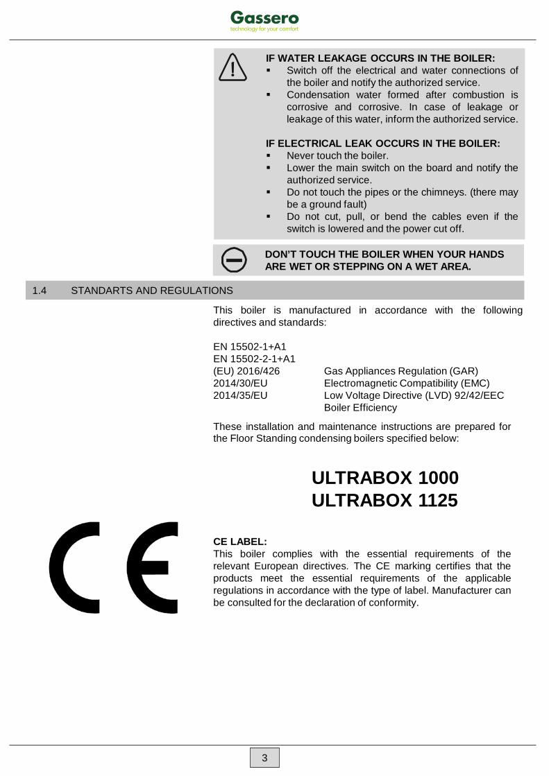
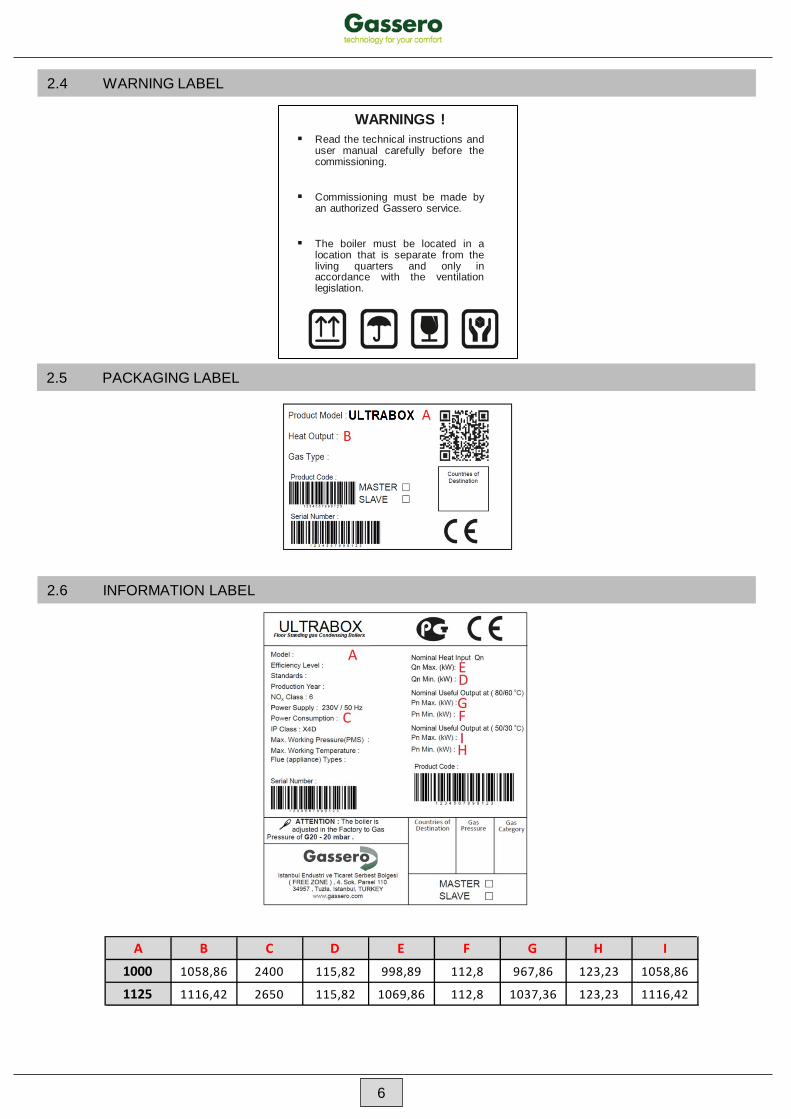
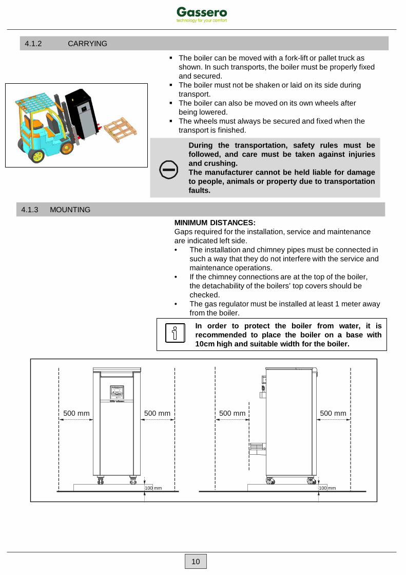
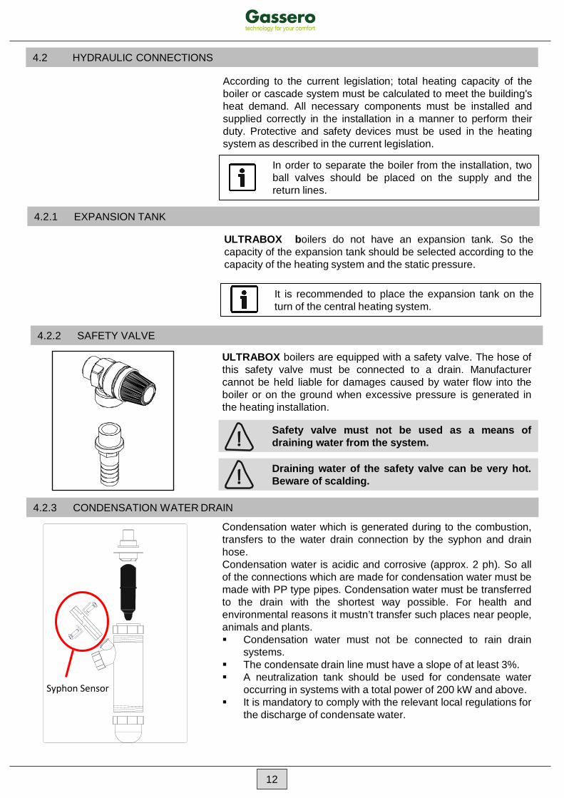
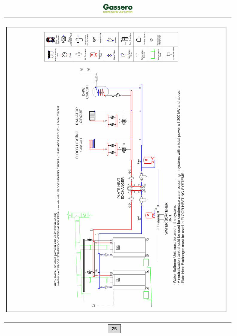
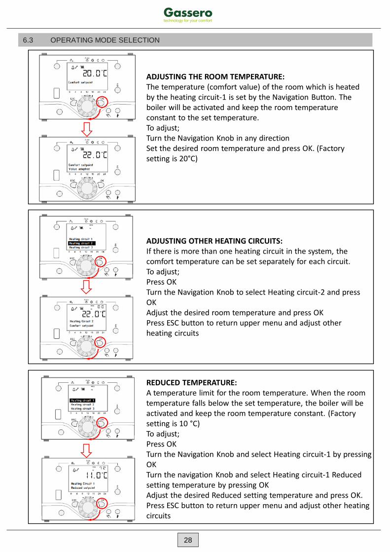
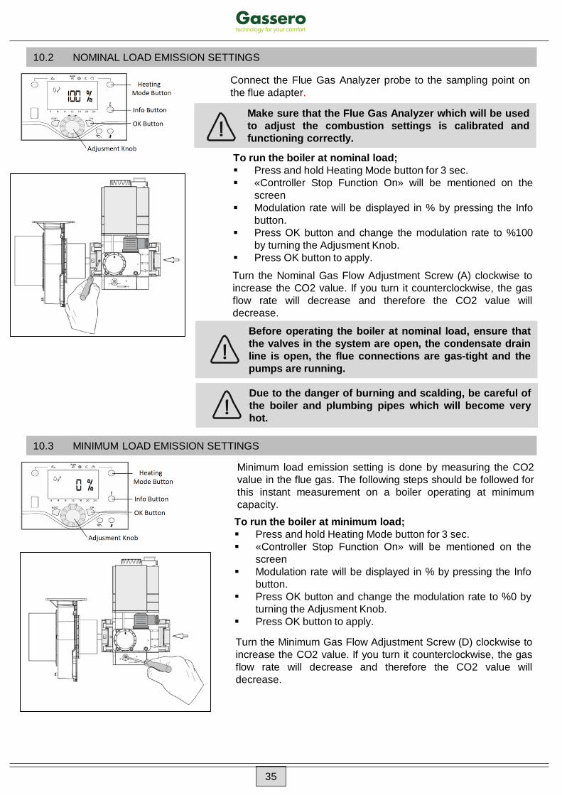