florida power and light company attn: mr. j. a. … · december 5, 2002 florida power and light...
TRANSCRIPT

December 5, 2002
Florida Power and Light CompanyATTN: Mr. J. A. Stall, Senior Vice President
Nuclear and Chief Nuclear OfficerP. O. Box 14000Juno Beach, FL 33408-0420
SUBJECT: ST. LUCIE NUCLEAR PLANT - NRC INSPECTION REPORT50-335/02-07 AND 50-389/02-07
Dear Mr. Stall:
On October 25, 2002, the NRC completed an inspection regarding your application for licenserenewal for your St. Lucie Nuclear Plant Units 1 and 2. The enclosed report documents theinspection findings, which were discussed on October 25, 2002, with Mr. D. Jernigan and othermembers of your staff in an exit meeting open for public observation at the St. Lucie site.
The purpose of this inspection was an examination of activities that support your application fora renewed license for the St. Lucie facilities. The inspection consisted of a selectedexamination of procedures and representative records, and interviews with personnel regardingthe process of scoping and screening plant equipment to select equipment subject to an agingmanagement review. For a sample of plant systems, inspectors performed visual examinationof accessible portions of the systems to observe any effects of equipment aging.
The inspection concluded that the scoping and screening portion of your license renewalactivities were conducted as described in your License Renewal Application and thatdocumentation supporting your application is in an auditable and retrievable form. With theexception of the items identified in this report, your scoping and screening process was successful in identifying those systems, structures, and components required to be consideredfor aging management.
In accordance with 10 CFR 2.790 of the NRC’s "Rules of Practice," a copy of this letter and itsenclosure will be available electronically for public inspection in the NRC Public Document Roomor from the Publicly Available Records (PARS) component of NRC’s document system (ADAMS). ADAMS is accessible from the NRC Web site at http://www.nrc.gov/reading-rm/adams.html (thePublic Electronic Reading Room).

FP&L 2
Should you have any questions concerning this letter, please contact us.
Sincerely,
\RA\
Harold O. ChristensenDeputy DirectorDivision of Reactor Safety
Docket Nos. 50-335, 50-389License Nos. DPR-67, NPF-16
Enclosure: Inspection Report 50-335/02-07, 50-389/02-07w/attachment
cc w/encl: (See page 3)

FP&L 3
cc:Senior Resident Inspector St. Lucie Plant U.S. Nuclear Regulatory CommissionP.O. Box 6090Jensen Beach, Florida 34957
Craig Fugate, DirectorDivision of Emergency PreparednessDepartment of Community Affairs2740 Centerview Drive Tallahassee, Florida 32399-2100
M. S. Ross, Attorney Florida Power & Light CompanyP.O. Box 14000Juno Beach, FL 33408-0420 Mr. Douglas Anderson County Administrator St. Lucie County2300 Virginia Avenue Fort Pierce, Florida 34982 Mr. William A. Passetti, ChiefDepartment of HealthBureau of Radiation Control2020 Capital Circle, SE, Bin #C21Tallahassee, Florida 32399-1741
Mr. Donald E. Jernigan, Site Vice PresidentSt. Lucie Nuclear Plant 6501 South Ocean Drive Jensen Beach, Florida 34957 Mr. R. E. RosePlant General Manager St. Lucie Nuclear Plant 6501 South Ocean Drive Jensen Beach, Florida 34957
Mr. J. T. VoorheesActing Licensing ManagerSt. Lucie Nuclear Plant6501 South Ocean DriveJensen Beach, Florida 34957
Mr. Don MothenaManager, Nuclear Plant Support ServicesFlorida Power & Light Company P.O. Box 14000Juno Beach, FL 33408-0420
Mr. Rajiv S. KundalkarVice President - Nuclear EngineeringFlorida Power & Light CompanyP.O. Box 14000Juno Beach, FL 33408-0420
Mr. J. KammelRadiological Emergency Planning AdministratorDepartment of Public Safety6000 SE. Tower DriveStuart, Florida 34997
Attorney GeneralDepartment of Legal AffairsThe CapitolTallahassee, Florida 32304
Mr. Steve HaleSt. Lucie Nuclear PlantFlorida Power and Light Company6351 South Ocean Drive Jensen Beach, Florida 34957-2000
Mr. Alan P. NelsonNuclear Energy Institute1776 I Street, N.W., Suite 400Washington, DC [email protected]
David LewisShaw Pittman, LLP2300 N Street, N.W.Washington, D.C. 20037
Mr. Stan Smilan5866 Bay Hill Cir.Lake Worth, FL 33463

U. S. NUCLEAR REGULATORY COMMISSION
REGION II
Docket Nos: 50-335, 50-389
License Nos: DPR-67, NPF-16
Report No: 50-335/02-07, 50-389/02-07
Licensee: Florida Power and Light Company (FPL)
Facility: St. Lucie Nuclear Plant, Units 1 & 2
Location: 6351 South Ocean DriveJensen Beach, FL 34957
Dates: October 21 - 25, 2002
Inspectors: R. Moore, Reactor InspectorM. Scott, Reactor InspectorK. Van Doorn, Reactor InspectorS. Vias, Reactor InspectorH. Wang, Operations Engineer, NRR
Approved by: Caudle Julian Team LeaderDivision of Reactor Safety

TABLE OF CONTENTS
Summary of Findings . . . . . . . . . . . . . . . . . . . . . . . . . . . . . . . . . . . . . . . . . . . . . . . . . . . IReport Details . . . . . . . . . . . . . . . . . . . . . . . . . . . . . . . . . . . . . . . . . . . . . . . . . . . . . . . . 1
Inspection Scope . . . . . . . . . . . . . . . . . . . . . . . . . . . . . . . . . . . . . . . . . . 1Findings . . . . . . . . . . . . . . . . . . . . . . . . . . . . . . . . . . . . . . . . . . . . . . . . . 1A. Evaluation of Scoping and Screening of Mechanical Systems . . . . . 1
1. Reactor Coolant System (RCS) . . . . . . . . . . . . . . . . . . . . . . . 22. Chemical and Volume Control System (CVCS) . . . . . . . . . . . 23. Containment Spray System (CS) . . . . . . . . . . . . . . . . . . . . . . 34. Safety Injection System (SI) . . . . . . . . . . . . . . . . . . . . . . . . . . 35. Instrument Air System (IA) . . . . . . . . . . . . . . . . . . . . . . . . . . . 36. Primary Makeup Water . . . . . . . . . . . . . . . . . . . . . . . . . . . . . 47. Extraction Steam . . . . . . . . . . . . . . . . . . . . . . . . . . . . . . . . . . 48. Containment Airborne Radioactivity Removal System (Unit 1 only) . . . . . . . . . . . . . . . . . . . . . . . . . . . . . . . . . . . . . . . . . . . . . 49. Component Cooling Water System (CCW) . . . . . . . . . . . . . . 410. Containment Isolation . . . . . . . . . . . . . . . . . . . . . . . . . . . . . 511. Intake Cooling Water System (ICW) . . . . . . . . . . . . . . . . . . 512. Spent Fuel Pool Cooling System (SFPC) . . . . . . . . . . . . . . . 513. Cathodic Protection (CP) . . . . . . . . . . . . . . . . . . . . . . . . . . . 614. Turbine Cooling Water (TCW), Unit 1 Only . . . . . . . . . . . . . 715. Containment Cooling (CC) . . . . . . . . . . . . . . . . . . . . . . . . . . 716. Emergency Cooling Canal (ECC) . . . . . . . . . . . . . . . . . . . . . 717. Service Water System (SW) . . . . . . . . . . . . . . . . . . . . . . . . 718. Containment Post Accident Monitoring . . . . . . . . . . . . . . . . 819. Auxiliary Feedwater and Condensate System . . . . . . . . . . . 820. Sampling System . . . . . . . . . . . . . . . . . . . . . . . . . . . . . . . . . 821. Waste Management System . . . . . . . . . . . . . . . . . . . . . . . . 822. Ventilation (HVAC-Plumbing and Draining Leak Detection System) . . . . . . . . . . . . . . . . . . . . . . . . . . . . . . . . . . . . . . . . . 823. Diesel Generators and Support Systems . . . . . . . . . . . . . . . 924. Main Feedwater and Steam Generator Blowdown Systems . 925. Air Blower . . . . . . . . . . . . . . . . . . . . . . . . . . . . . . . . . . . . . 10
B. Evaluation of Scoping and Screening of Electrical Systems . . . . . . 10C. Evaluation of Scoping and Screening of Structural Components . . 12
1. Component Cooling Water Areas . . . . . . . . . . . . . . . . . . . . 122. Condensate Storage Tank Enclosure . . . . . . . . . . . . . . . . . 133. Diesel Oil Equipment Enclosure . . . . . . . . . . . . . . . . . . . . . . 134. Emergency Diesel Generator Building . . . . . . . . . . . . . . . . . 145. Fire Rated Assemblies . . . . . . . . . . . . . . . . . . . . . . . . . . . . . 146. Fuel Handling Buildings . . . . . . . . . . . . . . . . . . . . . . . . . . . . 147. Fuel Handling Equipment . . . . . . . . . . . . . . . . . . . . . . . . . . . 158. The Unit 1 Fire House . . . . . . . . . . . . . . . . . . . . . . . . . . . . . 159. Intake Velocity Caps . . . . . . . . . . . . . . . . . . . . . . . . . . . . . . 1610. The Intake and Discharge Pipelines . . . . . . . . . . . . . . . . . . 1611. Intake, Discharge, and Emergency Cooling Canals . . . . . . 1612. Ultimate Heat Sink Dam (Barrier Wall) . . . . . . . . . . . . . . . . 1713. Intake Structures . . . . . . . . . . . . . . . . . . . . . . . . . . . . . . . . 17
2
14. Reactor Auxiliary Buildings . . . . . . . . . . . . . . . . . . . . . . . . . 1815. Reactor Containment Buildings . . . . . . . . . . . . . . . . . . . . . 1816. Steam Trestle Areas . . . . . . . . . . . . . . . . . . . . . . . . . . . . . 1917. Turbine Building . . . . . . . . . . . . . . . . . . . . . . . . . . . . . . . . . 1918. Switch Yard . . . . . . . . . . . . . . . . . . . . . . . . . . . . . . . . . . . . 19
D. Evaluation of Scoping and Screening of Fire Protection Systems . . . . . . . 20E. Visual Observations of Plant Equipment in Containment (Unit 1) . . . . . . . . 20F. Inspection Items From NRR Staff Review . . . . . . . . . . . . . . . . . . . . . . . . . . 22
Attachment 1 Supplemental Information Partial List of Persons Contacted . . . . . . . . . 26List of Documents Reviewed . . . . . . . . . . . . . . . . . . . . . . . . . . . . . . . . . . . . . . . . . . . . 27Attachment 2 St. Lucie Nuclear Plant License Renewal Inspection Plan . . . . . . . . . . 31Attachment 3 List of Acronyms Used . . . . . . . . . . . . . . . . . . . . . . . . . . . . . . . . . . . . . . 35

I
SUMMARY OF FINDINGS
IR 05000335-02-07, IR 05000389-02-07; 10/21-25 /2002; Florida Power and Light Company,St. Lucie Nuclear Plant, Units 1 & 2. License Renewal Inspection Program, Scoping andScreening.
This inspection of License Renewal (LR) activities was performed by four regional officeengineering inspectors, and one staff member from the office of Nuclear Reactor Regulation. The inspection program followed was NRC Manual Chapter 2516 and NRC InspectionProcedure 71002. This inspection did not identify any “findings” as defined in NRC ManualChapter 0612.
Documentation from the Scoping and Screening process was of good quality, detailed,thorough, and understandable. Minor exceptions were the following.
The inspectors noted that the applicant had omitted an air reservoir from the detailed list of LRin-scope components in the Main Feedwater screening summary report PSL-ENG-LRSC-00-035. The applicant took prompt corrective action to revise the Main Feedwater screeningsummary report to include this component. See paragraph II.A.24.
During the review, the inspectors found some inconsistencies in the structural screening reportPSL-ENG-LRSC-00-050. Thermo-lag fire barriers were listed in five table entries as not beingin scope when they should have been. The applicant made prompt changes to correct theseinconsistencies. See paragraph II.C.5.
NRC inspectors examined a substantial portion of plant safety related equipment. The NRC’soverall conclusion was the material condition of the plant was being adequately maintained.
Attachment 1 of this report lists the applicant personnel contacted and the documents reviewed. Attachment 2 lists the plant systems selected for inspection. A list of acronyms used in thisreport is provided in Attachment 3.

1
Report Details
I. Inspection Scope
This inspection was conducted by NRC Region II inspectors and members of the NRR staff tointerview applicant personnel and to examine a sample of documentation which supports thelicense renewal application (LRA). This inspection reviewed the results of the applicant’sscoping of plant systems and screening of components within those systems to identify the listof components that need evaluation for aging management. The team selected a sample ofplant systems, structures, and components (SSC) from the LRA scoping results to verify theadequacy of the applicant’s scoping and screening documentation and implementationactivities. For the selected in-scope systems/structures, the associated boundary drawings,and the active/passive and short/long lived determinations of the selected SSCs were reviewedto confirm the accuracy of the applicant’s results. In addition to the in-scope systems andstructures, some systems that the applicant had determined not to be in scope for licenserenewal were selected for inspection. The team reviewed supporting documentation andinterviewed applicant personnel to confirm the accuracy of the LRA conclusions. The SSCsselected for review during this inspection are listed in Attachment 2 to this report. For a sampleof plant systems, inspectors performed visual examination of accessible portions of the systemsto observe any effects of equipment aging.
II. Findings
A. Evaluation of Scoping and Screening of Mechanical Systems
The inspectors evaluated the applicant’s scoping and screening process for mechanicalcomponents by reviewing a number of plant systems that the applicant determined to be withinthe scope of license renewal. The applicant performed scoping and screening in two phases. The first phase (plant level scoping) was performed by listing all plant systems and structuresand identifying those that met one or more of the criteria of 10 CFR 54.4 for being in the scopeof license renewal (LR). The second phase (screening), to determine which componentsrequired aging management, consisted of: (1) for systems considered in-scope, identifyingintended functions of the system required to meet a criteria of 10CFR 54.4, (2) developingboundary drawings for each in-scope system identifying the portions of the system and thepassive components required to perform the intended functions, and (3) identifying which of therequired components were long-lived. Scoping and screening results were documented inapplicant’s scoping reports and License Renewal Screening Results Summary Reports for eachsystem.
The inspectors reviewed the applicant’s methodology for inclusion of non-safety-related (NSR)mechanical systems/components in scope which could affect safety-related (SR) systems. Theapplicant described their approach in a letter, L-2002-139, Response to NRC Request forAdditional Information, dated September 26, 2002. Essentially, for high and moderate energypiping, the applicant considered the affects of leakage, spray and physical interactions such asfalling, pipe whip, and jet impingement. For low energy piping, spray and leakage wereconsidered. Failure of air/gas systems was not considered credible. The applicant determinedall areas where NSR and SR systems were located together, conducted reviews of layout

2
drawings and piping detail drawings, and conducted walkdowns of areas to confirm locationsand portions of systems which needed to be added to the LR scope. Some areas did notrequire additional portions of systems to be added to the scope. For example, in containment,all high/moderate energy piping was designed as SR and equipment is designed to beprotected from leakage and spray. In some areas, the applicant’s systems are in an outdooratmosphere and equipment such as electrical enclosures are designed to withstand leakageand spray. The inspectors reviewed the applicant’s engineering evaluation, revieweddocumentation of the portions of systems added to LR scope, reviewed selected layout markupdrawings, discussed the process with responsible personnel, and walked down areas of theplant which did not contain additional in scope systems and areas where some additionalsystems were added. These areas included Emergency Diesel Generator (EDG) rooms, theintake structure, the AB switchgear rooms, the Unit 2 mechanical penetration room, the ReactorAuxiliary Building (RAB) -.5 elevation hallway, Safety Injection System (SI) and ContainmentSpray System (CS) areas in the RAB, and the Fuel Handling Buildings. The applicant’sprogram for identifying systems to be added to the LR scope for potential interactions of NSRwith SR equipment was thorough and the inspectors did not identify additional equipment whichshould be in scope. Additional walkdowns are also planned during an upcoming inspection.
The following systems/structures were reviewed:
1. Reactor Coolant System (RCS)
The RCS consists of systems and components designed to contain and support the nuclearfuel, contain the reactor coolant, and transfer the heat from the reactor to the steam and powerconversion system. For each unit, the system consists of four heat transfer loops connectedin parallel to the reactor vessel (RV). Each loop is connected to one of two steam generators,and contains a pump, loop piping, and instrumentation. Piping connections are provided in theRCS piping for auxiliary systems, such as safety injection (SI) and chemical and volume control(CVCS). For licensee renewal, the applicant included the following components in the LRA forthe RCS: reactor coolant loop pumps, piping, and components; presssurizer; RV (including thepressure boundary of the control element drive mechanisms); RV internals; and steamgenerators. All of the major passive components and associated piping, includinginstrumentation piping were considered in scope by the applicant. The inspectors reviewed theUpdated Final Safety Analysis Report (UFSAR), LR boundary drawings, selected steamgenerator drawings, and scoping and screening documents for the system. The inspectorsconcluded that the applicant had appropriately scoped and screened this system and identifiedthe components and their functions that were subject to aging management consistent with theSt. Lucie LRA and the rule.
2. Chemical and Volume Control System (CVCS)
The CVCS consists of components and systems required to provide a continuous feed andbleed for the RCS; maintain proper water inventory, chemistry, and purity in the RCS, includingmakeup for leakage; adjust concentration of boron for reactivity control; inject concentratedboric acid upon a safety injection; provide seal water for RCS pump shaft seals; provideauxiliary pressurizer spray; and provide an alternate charging path to the RCS. The systemcontains piping and valves and the following major components: boric acid makeup tanks,demineralizers, a volume control tank, boric acid makeup pumps, three charging pumps, andletdown and regenerative heat exchangers. The applicant considered all of the major

3
components and essentially all of the associated SR piping, including instrumentation piping, inscope for license renewal. The inspectors reviewed the UFSAR, LR boundary drawings, andscoping and screening documents for the system. The inspectors concluded that the applicanthad appropriately scoped and screened this system and identified the components and theirfunctions that were subject to aging management consistent with the St. Lucie LRA and therule.
3. Containment Spray System (CS)
The CS functions to remove sufficient heat to maintain the containments below their designpressure and temperature limits following design basis events. In addition, chemicals areinjected into the suction lines to control PH in the containment sump and for iodine absorption. The systems consists of two pumps that take suction from the refueling water tank (RWT) andspray water from nozzles located near the top of the containment. When the RWT is empty,the pump suction is switched to the containment sump and the shutdown cooling heatexchangers are used to remove heat. Unit 1 has a sodium hydroxide chemical addition tank. Unit 2 has hydrazine pumps and a hydrazine storage tank. Unit 2 also has trisodium phosphatedodecahydrate stainless steel mesh baskets near the containment sump for PH control whichare screened with civil/structural components. The applicant included all of the safety-relatedportion of the system in scope for LR. The inspectors reviewed the system scoping andscreening documents, LRA boundary drawings, and the UFSAR, and walked down portions ofthe system. The inspectors concluded that the applicant had appropriately scoped andscreened this system and identified the components and their functions that were subject toaging management consistent with the LRA and the rule.
4. Safety Injection System (SI)
The safety injection system provides emergency core cooling and reactivity control during andfollowing design basis accidents. The SI contains both high pressure and low pressureportions. Portions of the SI are also used for shutdown cooling and containment spray cooling. The system includes two high pressure and two low pressure pumps, heat exchangers, safetyinjection tanks, and associated valves, piping and components. The applicant included all ofthe SR portion of the system in scope except a section of the high pressure portion which isabandoned in place. The inspectors reviewed the system scoping and screening documents,reviewed LRA boundary drawings, reviewed the UFSAR and performed field walkdowns of theaccessible portions of the system. The inspectors concluded that the applicant hadappropriately scoped and screened this system and identified the components and theirfunctions that were subject to aging management consistent with the LRA and the rule.
5. Instrument Air System (IA)
The IA system provides a dry, oil-free source of air for instrumentation, controls, and pneumaticvalves. The system contains four compressors for each Unit and associated valves,instruments, piping, orifices, tubing, fittings, receivers, accumulators, filters, strainers, and heatexchangers. The applicant considered the SR portions of IA and portions which support stationblackout (SBO) and fire events in scope. Differences in original design commitments resultedin two of four compressors in Unit 1 being in scope and all four Unit 2 compressors in scope. The applicant screened the Service Air System with IA and considered portions associated withcontainment penetrations in scope. The applicant also screened the Bulk Gas Systems with IA

4
and considered a portion of the hydrogen supply line to the RAB for Unit 2 in scope. Theinspectors reviewed the UFSAR, LR boundary drawings, and scoping and screening documentsfor IA. The inspectors concluded that the applicant had appropriately scoped and screened thissystem and identified the components and their functions that were subject to agingmanagement consistent with the LRA and the rule.
6. Primary Makeup Water
This system functions to provide treated, demineralized water for makeup to various systemsthroughout the plant. The system contains tanks, pumps, valves, piping, and associatedcomponents. The applicant considered SR portions of the system, although the system doesnot perform any safety related functions, and portions whose failure could affect SR equipmentto be in scope. Also, for Unit 2, portions which were part of environmentally qualified equipmentand portions which supported response to fire events were considered in scope. Theinspectors reviewed LR boundary drawings, a plant fire fighting procedure, plant drawings, theUFSAR, and scoping and screening documents for the system. The inspectors concluded thatthe applicant had appropriately scoped and screened this system and identified thecomponents and their functions that were subject to aging management consistent withe LRAand the rule.
7. Extraction Steam
This system functions to extract steam from the main turbine for heating of main feedwater. NoSR functions are performed by this system. The applicant concluded that this system was inscope for LR. The inspectors reviewed the UFSAR and plant drawings for the system. Theinspectors found the applicant’s conclusion acceptable.
8. Containment Airborne Radioactivity Removal System (Unit 1 only)
This system contains two units of fans and filters which function to remove airborne radioactivityin particulate and iodine form in containment. The system does not perform a safety relatedfunction. The applicant concluded that this system was not in scope for LR. The inspectorsreviewed the UFSAR and plant drawings for the system. The inspectors found the applicant’sconclusion acceptable.
9. Component Cooling Water System (CCW)
The CCW system is a closed loop cooling water system that provides a heat sink for safety-related and non-safety-related components during normal and emergency operation. Some ofthe more important cooling loads are: the shutdown cooling heat exchangers; safety-relatedpump seal and bearing coolers; control room cooling units; the spent fuel pit heat exchanger;and the emergency containment coolers. Typical loads are described in Table 9.2-5 of the Unit1 UFSAR. Heat from these systems and components is transferred to the intake cooling water(ICW) system at the CCW heat exchangers’ interface. The major components included arethree CCW pumps, two CCW heat exchangers, a CCW surge tank, two redundant coolantloops, and associated piping, valves and instrumentation. The inspectors reviewed the UFSAR,LR boundary drawings, and scoping and screening documents for the system. The applicantconsidered most of the CCW system in LR scope, but did exclude several non-safety relatedcomponents such as the chemical addition tank and the non-essential header for the non-safety

5
loads. The inspector did not consider the omissions a problem; the non safety subsections areautomatically isolated or can be isolated from the remainder of the system in emergencyconditions. An inspector performed a field walkdown of accessible portions of the system andfound it to be in good condition. The inspectors found that the applicant had performed scopingand screening for this system in accordance with the methodology described in the St. LucieLRA and the rule.
10. Containment Isolation
Containment isolation is an engineered safety feature that provides for the automatic closure ofcontainment penetrations upon accident signal to prevent leakage of radioactive material to theenvironment. Containment isolation is described in UFSAR section 6 and had been placed inLRA scope. UFSAR Tables 6.2-16 and 6.2-52 (Unit 1 and 2, respectively) list the mechanicalpenetrations. The electrical penetrations are addressed under separate LRA sections (2.4 and2.5 instead of the mechanical section 2.3.2.3) and are also in scope. The inspectors walkeddown several of the penetration areas finding them in adequate condition. The inspectorsconcluded that the applicant had appropriately scoped and screened these systems andidentified the mechanical components and their functions that were subject to agingmanagement consistent with the LRA and the rule.
11. Intake Cooling Water System (ICW)
The ICW system provides cooling water to remove heat from the CCW system, steamgenerator open blowdown (SGOBD), and the Turbine Cooling Water (TCW) system. Thesystem for each unit consists of three pumps, two redundant piping headers, and associatedvalves and instrumentation. Flow from the ICW enters the tubes of the CCW and non-safetyheat exchangers. ICW piping to the non-safety TCW and SGOBD exchangers is not in scopeand is automatically isolated by valves under various emergency conditions. The ICW pumpstake suction from the salt water of the unit common intake canal at the combined intakestructure for ICW and Circulating Cooling Water (main turbine exhaust steam cooling). Afterremoving heat at the heat exchangers, the flow is returned to a common discharge canal. Theinspectors reviewed the UFSAR Section 9.2.1; LR boundary drawings; and scoping andscreening documents for the ICW system. The inspectors also walked down portions of thesystem on both units finding them in generally adequate condition. Large segments of the ICWpiping are beneath ground and subject to routine internal inspection (see cathodic protectiondiscussion). The applicant concluded that the portions of the system, which assure coolingwater to the CCW system were in scope for LR. The inspectors concluded that the applicanthad performed scoping and screening for the ICW system in accordance with the methodologydescribed in the St. Lucie LRA and the rule.
12. Spent Fuel Pool Cooling System (SFPC)
The SFPC system removes stored spent fuel decay heat from the spent fuel pool and filtersand demineralizes the water in the pool. Each unit has a spent fuel pool and SFPC systemwhich consists of two recirculation pumps, a purification pump, a pool, a pool liner, a skimmer,purification filter, ion exchanger, two strainers, one (or two as in the case of Unit 2) heatexchanger, and associated piping, valves, and instrumentation. The inspectors reviewed theUFSAR, Section 9.1; LR boundary drawings; and scoping and screening documents for theSFPC system. The recirculation pumps, heat exchangers, pool, associated recirculation piping,

6
and associated instrumentation were in scope. The inspectors performed a walkdown of theassociated structures and components finding them in adequate condition. The inspectorsconcluded that the applicant had performed scoping and screening for the SFPC system inaccordance with the methodology described in the St. Lucie LRA and the rule.
13. Cathodic Protection (CP)
The CP schemes for the units were not placed in scope by the applicant. This excluded theelectrical ground mat system, which is in scope. The basis for this decision resides in theapplicant’s responses to NRC Requests for Additional Information (RAIs) in FPL letters L-2002-157 and L-2002-166 referenced in this report. The 157 letter text reads in part:
NRC Question
“Referring to Section 3.5.2.2.2 of the LRA, discuss St. Lucie’s operating experienceregarding the effectiveness of its application of the impressed current cathodicprotection system to prevent the corrosion of carbon steel in fluid structural componentsthat are exposed to raw water. Is the impressed current cathodic protection systemused for items other than the sheet piling? If yes, briefly discuss the operatingexperience with respect to the effectiveness of these applications.
FPL Response
Inspection of the accessible portions of the sheet piling revealed no significant loss ofmaterial. The below groundwater portions of the sheet piling are not accessible. However,since bare steel within the submerged and subsoil zones has corrosion rates that aresimilar to, or lower than, corrosion rates for atmospheric conditions, the undergroundportions of the sheet piling are considered to be in similar condition.
The impressed current cathodic protection systems that protect the discharge canal nosesheet piling and the ultimate heat sink dam sheet piling do not protect any other items.There are additional impressed current cathodic protection systems for other componentsand structures (e.g., barge slip, condenser water boxes, turbine cooling water heatexchangers, etc.). Based on St. Lucie plant-specific operating experience, these systemshave proven to be effective in providing corrosion protection.”
As clarified in FPL Response to RAI B3.2.14-2 (see FPL letter L-2002-166):
“As described in LRA Appendix B, Section 3.2.14 (page B-58), the Systems and StructuresMonitoring Program (SSMP) employs the visual inspection method. Structures andstructural commodities are visually inspected on an area basis, and system commoditiesand components are visually inspected on a system basis. Conditions documented andevaluated via the Corrective Action Program may employ other methods, such asvolumetric examination and computed radiography, to determine the extent of degradation.SSMP will be enhanced to include monitoring of interior surfaces.”
These positions that the CP system does not need to be in LR scope have been accepted by theNRC in this case and for Turkey Point LRA. The inspectors will review preventive maintenanceand surveillance programs (section 3.2.11 in the LRA) and SSMP implementation during the next

7
inspection period. The inspectors concluded that the applicant had performed scoping andscreening for the CP systems in accordance with the methodology described in the St. Lucie LRAand the rule.
14. Turbine Cooling Water (TCW), Unit 1 Only
TCW is a non-safety related closed-loop system used to remove heat from the main turbine andother components in the secondary, including the instrument air (IA) compressors. TCW isdiscussed in Section 9.2.4 of the UFSAR. TCW components associated with IA on Unit 1 havebeen addressed in the LRA. Unit 2 IA is not credited in station blackout (SBO) scenarios as it ison Unit 1. Specifically, the Unit 1 atmospheric dump valves (ADV) are air operated and to operatein a SBO event require IA compressors to be powered from the Unit 2 emergency diesel generatorsvia a SBO electrical cross connect. Thus, the Unit 1 TCW manually isolated piping segment isrequired to be operable during an SBO event cooling the compressor(s). The ADVs on Unit 2 areDC powered. The inspectors reviewed the UFSAR, Section 6; LR boundary drawings; and scopingand screening documents for the TCW system. The inspectors concluded that the applicant hadperformed scoping and screening for the TCW system in accordance with the methodologydescribed in the St. Lucie LRA and the rule.
15. Containment Cooling (CC)
CC is a subsystem in the CCW flow path. The four per unit CC air to fluid heat exchangers giveup containment heat to the CCW flow for removal in normal and accident conditions. All of thesubsystem’s components were in scope. The inspectors reviewed the UFSAR; LR boundarydrawings; and scoping and screening documents for the CC system. The inspectors concludedthat the applicant had performed scoping and screening for the CC system in accordance with themethodology described in the St. Lucie LRA and the rule.
16. Emergency Cooling Canal (ECC)
The safety-related ICW system normally draws salt water from the Atlantic Ocean via three largepipes that fill the intake canal. The canal water is the ultimate heat sink for the plants. Located onthat same canal is an ultimate heat sink dam that separates the canal from the intercoastalwaterway (a sound locally called the Indian River). For whatever reason, should the normal waterflow be unavailable, two valves in the dam can be opened to provide flow from the waterway to thecanal. The mechanical components of the dam are in scope. The inspectors reviewed the UFSARSection 9.2.7; LR boundary drawings; Table 3.3-5 of the LRA and scoping and screeningdocuments for the ECC system. The inspectors concluded that the applicant had performedscoping and screening for the ECC system in accordance with the methodology described in theSt. Lucie LRA and the rule.
17. Service Water System (SW)
Service water supports Fire Protection and supplies water to the plant washdown stations,decontamination facilities, and potable water system. The SW is a pressure boundary at interfacepoints for the FP system, its tanks contain the FP water source, and runs in areas were NSR/SRpotential interaction conditions have been identified by the applicant. The inspectors walked downportions of the SW and FP systems finding them in adequate condition. The inspectors reviewedthe UFSAR Section 9.5A; LR boundary drawings; Table 3.3-13 of the LRA and scoping and

8
screening documents for the SW system. The inspectors concluded that the applicant hadperformed scoping and screening for the SW system in accordance with the methodologydescribed in the St. Lucie LRA and the rule.
18. Containment Post Accident Monitoring
This system includes the subsystems of Containment Hydrogen Monitoring, Post AccidentSampling (Unit 2 only), and Containment Atmosphere Radiation Monitoring. The mechanicalcomponents included in the LR scope for aging management review included piping, valves, flexhoses, tubing, sample vessels, and bolting. The inspectors reviewed the system scoping andscreening documents, design basis information, and the applicable UFSAR sections. Theinspectors concluded that the applicant had performed scoping and screening for this system inaccordance with the LRA and the Rule.
19. Auxiliary Feedwater and Condensate System
This system supplies feedwater to the steam Generators when normal feedwater sources are notavailable. The components included in the LR scope for aging management review included theCondensate Storage Tanks (CST) as the water source, piping, valves, and pumps to provide a flowpath from the CST to the Steam Generators. The inspectors reviewed the system scoping andscreening documents, design basis information, LR boundary drawings, and the applicable UFSARsections. The inspectors concluded that the applicant had performed scoping and screening forthis system in accordance with the LRA and the Rule.
20. Sampling System
This system provides a means to obtain samples from the Reactor Coolant System and auxiliarySystems during all modes of operation for chemical and radiological analysis. The systemcomponents subject to aging management review included piping, tubing, valves, and bolting. Theinspectors reviewed the system scoping and screening documents, design basis information, LRboundary drawings and the applicable UFSAR sections. The inspectors concluded that theapplicant had performed scoping and screening for this system in accordance with the LRA andthe Rule.
21. Waste Management System
This system collects, monitors, and processes potentially radioactive reactor plant wastes prior torelease or removal from the plant site. This system includes three subsystems: liquid, gaseous,and solid waste management. It also include safeguards pump room drains and equipment andfloor drainage. Waste Management components within the LR scope for aging managementreview include valves, strainers orifices, clean-out plugs, piping and fittings. The inspectorsreviewed the system scoping and screening documents, design basis information, LR boundarydrawings and the applicable UFSAR sections. The inspectors concluded that the applicant hadperformed scoping and screening for this system in accordance with the LRA and the Rule.
22. Ventilation (HVAC-Plumbing and Draining Leak Detection System)
Ventilation provides for heating, ventilation and air conditioning to various buildings androoms/areas throughout the plant. Ventilation includes the following subsystems: Control Room

9
Air Conditioning, Emergency Core Cooling Systems Area Ventilation, Fuel handling buildingVentilation (Unit 2 only), Intake Structure Ventilation (Unit 2 only), Miscellaneous Ventilation (Unit1 only), Reactor Auxiliary Building Electrical and Battery room ventilation, Reactor Auxiliary BuildingMain Supply and Exhaust, and Shield Building Ventilation. Ventilation mechanical componentsidentified in the LR scope for aging management review include valves, filter housings, heatexchangers, flexible connections, ducts, demisters, thermowells, orifices, structural supports, tubingand piping. The inspectors reviewed the system scoping and screening documents, design basisinformation, LR boundary drawings and the applicable UFSAR sections. The inspectors concludedthat the applicant had performed scoping and screening for this system in accordance with the LRAand the Rule.
23. Diesel Generators and Support systems
The diesel generators provide emergency AC power to the onsite electrical distribution systemupon loss of normal electrical supply to assure the capability for a safe and orderly plant shutdown.The diesel generator support systems include the Air Intake and Exhaust System, Air Start System,Fuel Oil System, Lube Oil System, and the Cooling Water System. Mechanical componentsidentified in the LR scope for aging management review include pumps, valves, heat exchangers,silencers, tanks, flame arrestors, filters, strainers, flexible hoses, expansion joints, orifices,thermowells, piping, tubing and fittings. The inspectors reviewed the system scoping andscreening documents, design basis information, LR boundary drawings and the applicable UFSARsections. The inspectors concluded that the applicant had performed scoping and screening forthis system in accordance with the LRA and the Rule.
24. Main Feedwater and Steam Generator Blowdown Systems
These systems provide sufficient water flow to the steam generators to maintain an adequate heatsink for the Reactor Coolant System during normal operation, provide for Main Feedwater andSteam Generator Blowdown isolation following a postulated LOCA or steam line break event, andassist in maintaining stream generator water chemistry. The mechanical components identified inthe LR scope for aging management review included hydraulic accumulators and components forthe fast closure of the Main Feedwater Isolation valves, and valves, piping, tubing and fittingsnecessary for isolation of the Steam Generators’ Main Feedwater lines and Blowdown lines. Theinspectors reviewed the system scoping and screening documents, design basis information, LRboundary drawings and the applicable UFSAR sections. The LR boundary for the SteamGenerator Blowdown System included normally open valves as boundary valves. The inspectorsverified that station procedures provided direction to close the valves in a fire event, for which thosevalves were included in the LR scope. The inspectors concluded that the applicant had performedscoping and screening for this system in accordance with the LRA and the Rule. One minorexception was noted.
The inspectors noted that the applicant had omitted a mechanical passive component from thedetailed list of LR in-scope components in the Main Feedwater screening summary report (PSL-ENG-LRSC-00-035). This component was an air reservoir on the pneumatic-hydraulic actuationsystem for fast closure of the Unit 2 Main Feedwater Isolation valves. This component was shownon Anchor/Darling Valve Co. drawing W8020821 F, Schematic for Anchor/Darling Self-ContainedHydraulic Actuator Non-Redundant, revision F. The applicant’s prompt corrective action was torevise the summary report to include this component. The inspectors were shown the correcteddocument prior to the end of this inspection.

10
25. Air Blower
This system/equipment functions in conjunction with the Steam Generator Blowdown TreatmentSystem to agitate the resin in the spent resin tank prior to transfer of resin from the tank. Thesystem/equipment provides no safety related function, is not required to mitigate the effects of apostulated event, nor supports the regulated events included in LR Rule. The inspectors reviewedthe UFSAR and Steam Generator Blowdown System drawing and concluded there was adequatebasis for exclusion of this system/equipment from the LR scope.
B. Evaluation of Scoping and Screening of Electrical Systems
The inspectors observed that the scoping and screening of electrical systems employedsignificantly different methods than the mechanical or structural disciplines. During this inspectionthe inspectors reviewed an Engineering Evaluation report PSL-ENG-LRSC-00-052, Rev. 2, 8/29/02,License Renewal Screening Results for Electrical/I&C Component Commodity Groups. Theprocedure described how the applicant accomplished scoping and screening of electricalcommodities to determine those needing an aging management review.
The method used to determine which electrical and I&C components are subject to an agingmanagement review was organized based on component commodity groups. The primarydifference in this method versus the one used for mechanical systems and structures is the orderin which the component scoping and screening steps are performed. This method was selectedfor use with the electrical and I&C components since most electrical and I&C components areactive, thus, the applicant concluded that this method provided the most efficient means fordetermining electrical and I&C components that require an aging management review. The methodis consistent with the industry guidance documented in NEI 95-10.
Electrical/I&C component commodity groups associated with electrical, I&C, and mechanicalsystems within the scope of license renewal were identified. This step included a complete reviewof design drawings and electrical/I&C component commodity groups in the plant componentdatabase. A description and function for each of the electrical/I&C component commodity groupswere identified. The electrical/I&C component commodity groups that perform an intended functionwithout moving parts or without a change in configuration or properties [screening criterion of 10CFR 54.21(a)(1)(i)] were identified. For the resulting passive electrical/I&C component commoditygroups, component commodity groups that are not subject to replacement based on a qualified lifeor specified time period [screening criterion of 10 CFR 54.21(a)(1)(ii)] were identified as requiringan aging management review. Electrical and I&C component commodity groups included in the10 CFR 50.49 Environmental Qualification Program were considered to be subject to replacementbased on qualified life, and thus eliminated from the list. Next certain passive, long-livedelectrical/I&C component commodity groups that do not support license renewal system intendedfunctions were eliminated. Finally the in-scope equipment identified as requiring an agingmanagement review were compared to the NRC’s Generic Aging Lessons Learned report to ensurethat differences are valid and justified. The resulting list of electrical and I&C componentcommodity groups subject to an aging management review was:
Cables and Connections (including insulated cables and connections, uninsulated groundconductors, splices, and terminal blocks not included in the Environmental Qualification Program.

11
The inspectors found the methodology and the conclusions reached by the applicant to besatisfactory.
By a letter dated April 1, 2002, the NRC issued a staff position to the NEI, which described that theoffsite power system, which is used to connect the plant to the offsite power source and would beused to recover from a Station Blackout (SBO), should be included within the scope of licenserenewal. In RAI 2.1-2 NRC asked FPL to address the staff position and describe what additionalequipment would be brought into LR scope for recovery from a SBO. In their response to the RAI,FPL contended that restoration of offsite power is not relied on to meet the requirements of theSBO Rule for St. Lucie. However, FPL performed an evaluation to determine the additionalelectrical and structural components that are in the scope of license renewal for restoration ofoffsite power at St. Lucie. For those electrical and structural components determined to be withinthe scope of license renewal and requiring an aging management review (AMR), an AMRevaluation was performed. The results of that evaluation were that the following passive electricalcomponents are in the scope of LR.
DC control and power (lead sheath) cables
All Aluminum Alloy Conductor (Type AAAC) transmission conductors between the StartupTransformers and circuit breakers
High voltage insulators associated with the transmission conductors
Switchyard bus and connections between the Startup Transformers and circuit breakers
Nonsegregated-phase bus between the Startup Transformers and the non safety-related 4.16 kV switchgear
The cables were included in the AMR for non-EQ cable. The AMR evaluation concluded that theremaining electrical transmission equipment located outdoors has shown no history of deteriorationand thus there are no aging effects requiring management.
In their RAI response FPL stated that consistent with the NRC position, the additional structuralcomponents included in the scope of license renewal as meeting the scoping criteria of 10 CFR54.4(a)(3) for restoration of offsite power are as follows:
Switchyard
Startup Transformer circuit breaker foundations
Covered cable trenches
Electrical component supports
Switchyard control building
DC electrical enclosures
Cable trays
Startup Transformer circuit breaker electrical enclosures
Transmission towers

12
Transmission tower foundations
Turbine Buildings
Switchgear rooms
Switchgear enclosures
Switchgear supports
Nonsegregated-phase bus supports
Yard Structures
Transmission towers
Nonsegregated-phase bus supports
Nonsegregated-phase bus foundations
Startup Transformer foundations
4.16 kV Switchgear foundations
Transmission tower foundations
Electrical duct banks and manholes
An AMR evaluation of these components based on AMRs of St. Lucie structural components of thesame materials exposed to the same environments yields the result that electrical componentssupports, DC electrical enclosures, cable trays, and transmission towers have no aging effectsrequiring management. The other structural components will be included in the Systems andStructures Monitoring Program aging management program.
C. Evaluation of Scoping and Screening of Structural Components
1. Component Cooling Water Areas
The Units 1&2 component cooling water areas (CCWA) house the safety related componentcooling water pumps and heat exchangers , therefore, the Units 1&2 CCWA structures andstructural components are within the scope of license renewal. The CCWA is designed to seismicClass 1 requirements. Table 1-1 of Attachment 1, “Component Cooling Water Areas,” Revision1, 10/17/01 to PSL-ENG-LRSC-00-050, “St Lucie Units 1 & 2 License Renewal Screening Results -Structures and Structural Components,” Revision 3, 9/20/02 lists the screening results of theCCWA. The only component that was considered not to need aging management review is theUnit 2 CCWA trolley hoist. The inspectors agreed with this assessment.

13
2. Condensate Storage Tank Enclosure
The condensate storage tank (CST) enclosures of both units are cylindrical reinforced concretestructures designed to seismic class 1 requirements. They are primarily used for horizontal tornadogenerated missile protection of the tanks. The structures are supported on reinforced concretemat. The top of the Unit 1 CST enclosure is open but enclosed with steel framing and grating. Thetop of the Unit 2 enclosure is closed with a shallow 5 inches thick precast concrete dome roof,overlaid with an additional 19 inches of reinforced concrete. All the enclosure structures andstructural components are within the scope of license renewal as listed in Table 2-1 of Attachment2, “Condensate Storage Tank Enclosure,” Revision 1, 10/20/01 to PSL-ENG-LRSC-00-050. Bothenclosures have 3 feet thick reinforced concrete foundation mat and 2 feet reinforced concretewalls. The steel mesh door of the Unit 2 enclosure is screened out of license renewal because itdoes not perform any safety related intended function(s). The door is installed to keep birds out.
In response to RAI 2.4.2.3-1, the applicant stated that concrete above groundwater and componentsupports are within the scope of license renewal. The staff was concerned that bolts, base mat andstructural fills are not identified as in scope. The applicant responded to the inspectors that allconcrete of the CST enclosure are above groundwater level and bolts are considered to becomponent supports. The structural fills are fills that are between the CST and the base matenclosed by the concrete ring walls, therefore, they are inaccessible. The inspectors walked downthe CST enclosure and found they are in good shape. The steel anchor bolts are tightly securedand the concrete is in good condition. Figures 2.4-17 and 2.4-18 of the Unit 1 UFSAR shows theaverage ground water level is about +6' and elevation of the bottom of the CST enclosurefoundation is at +10', therefore, all concrete components are above the ground water table. Theinspectors considered the applicant’s determination acceptable.
3. Diesel Oil Equipment Enclosure
Attachment 3, “Diesel Oil Equipment Enclosure,” Revision 1, 10/22/01 to PSL-ENG-LRSC-00-050describes that the Unit 1 diesel oil transfer pumps are completely enclosed and protected byreinforced concrete walls designed to seismic class 1 requirements. The Unit 1 diesel oil storagetanks are located outdoors on concrete foundations surrounded by a 5-foot 6-inch highoverflow/rupture protection reinforced concrete containment wall.
The Unit 2 diesel oil transfer pumps and diesel oil storage tanks are located within a fully enclosedreinforced concrete seismic class 1 structure. The entire enclosures of Units 1&2 are within thescope of license renewal. The screening results are listed in Table 3-1 of Attachment 3 to PSL-ENG-LRSC-00-050. The inspectors had no concerns with the results.

14
4. Emergency Diesel Generator Building
The emergency diesel generator (EDG) buildings of both units are seismic class 1 reinforcedconcrete structures, housing duplicate diesel generating units separated by reinforced concretewalls. The diesel generators are supported on reinforced concrete mats. Both EDG buildings arewithin the scope of license renewal.
The screening results of the EDG buildings are listed in Table 4-1 of Attachment 4, “EmergencyDiesel Generator Building,” Revision 1, 10/21/02 to PSL-ENG-LRSC-00-050. Except itemsscreened in other documents and active components, all structural components are determinedto need aging management review. Figures 4-1 and 4-2 of Attachment 4 show the evaluationboundaries of the EGD buildings of Units 1&2, respectively. The inspectors agreed with theapplicant’s results.
5. Fire Rated Assemblies
Fire rated assemblies are found throughout the plant. They include fire barriers, fire doors, firedampers, and penetration seals. In order to ensure that safe shutdown capability is not impairedin the event of a single fire, essential components are separated by fire barriers, radiant energyshields, flame impingement shields, conduit fire wrap, and conduit plugs.
Fire doors are provide at fire area boundaries in accordance with 10 CFR 50, Appendix Rrequirements. Fire dampers are provided to prevent the spread of fire through HVAC penetrations.Penetration seals are provided to maintain the integrity of fire barriers at barrier penetrations. Allfire rated assemblies are within the scope of license renewal.
Table 5-1 of Attachment 5, entitled “Fire Rated Assemblies,” Revision 2, 2/15/02 to PSL-ENG-LRSC-00-050 lists the screening results of the fire rated assemblies. During the review, theinspectors found some inconsistencies. There are thermo-lag 330-1 and 770-1 fire barriers listedin Table 5-1 with different aging management review results. All thermo-lag barriers are in LRscope and require an aging management review. The applicant agreed with the inspectors andmade prompt changes to correct these inconsistencies in Revision 4 to the document PSL-ENG-LRSC-00-050. The inspectors agreed with the corrected assessment.
6. Fuel Handling Buildings
Attachment 6, “Fuel Handling Buildings,” Revision 2, 2/15/02 to PSL-ENG-LRSC-00-050describes that the fuel handling buildings are seismic class 1 reinforced concrete structures. Thestructures house the spent fuel pool which is a cast-in-place steel lined reinforced concrete tankstructure. The fuel handling buildings also house heating and ventilating equipment, fuel pool heatexchanger, fuel pool filters, fuel pool pumps, and fuel pool purification pumps. In addition, the fuel

15
handling buildings provide space for the storage of new fuel and decontamination area for spentfuel casks and other equipment. The fuel handling buildings provide support to safety related andnon-safety related equipment and systems as well as protection from the environment, such asearthquake and tornado, etc. Both fuel handling buildings are within the scope of license renewal.
Section 5.0 of this attachment indicates that the Unit 1 airtight door and seal are not in scope. Thescreening results listed in Table 6-1 of this attachment also indicates that certain components donot require an aging management review. License renewal application Table 2.1-1 indicate thatfor a Unit 1 fuel handling accident, the releases are well within the 10CFR100 limits. Theinspectors agreed with this assessment.
7. Fuel Handling Equipment
The fuel handling equipment is an integrated system of equipment for refueling the reactor. Itprovides for handling and storage of fuel assemblies from receipt of new fuel to storage of spentfuel. Major components of the system are the refueling machine, the fuel transfer equipment, thespent fuel handling machine, the new fuel elevator, and the new fuel crane.
The refueling machine moves fuel assemblies into and out of the core and between the core andthe transfer equipment. The fuel transfer equipment moves the fuel between reactor containmentbuilding and the fuel handling buildings via the transfer tube. The spent fuel handling machinemoves fuel between the transfer equipment, the fuel storage racks in the spent fuel pool, the spentfuel shipping cask and the new fuel elevator.
All fuel handling equipment components are evaluated as part of the containment buildings and thefuel handling buildings. Pages 2&3 of Attachment 7, “Fuel Handling Equipment,” Revision 1,10/15/01, to PSL-ENG-LRSC-00-050 lists all the major components and concludes that the fuelhandling equipment is in the scope of license renewal. The inspectors agreed with this conclusion.
8. The Unit 1 Fire House
The Unit 1 fire house is a concrete block structure with concrete foundation. The structure islocated near the Unit 1 CST enclosure. The fire house is used as a storage room to store firefighter’s equipment, such as clothing, oxygen bottles and other breathing apparatus. Theinspectors walked down the structure and found it is located sufficiently far away from any safetyrelated structures or systems and it does not perform any safety related intended functions asdescribed in 10 CFR54.4, therefore, the inspectors agreed that this structure is not within the scopeof license renewal.

16
9. Intake Velocity Caps
The intake velocity caps are attached to the end of the intake pipe located in the Atlantic Ocean,approximately 1200 feet from the shore. Drawing 2998-G-663-S01 shows the location and Drawing8770-G-664-2 shows the details of the caps. The caps consist of a flat plate supported verticallyby steel columns. Water flows horizontally through the spaces between the vertical columns intothe intake pipe. This arrangement reduces the velocity of the intake flow to minimize fishentrapment and to avoid damaging marine life. In case the caps are damaged, cooling water canbe brought in from the Indian River via the Ultimate Heat Sink Dam through the emergency coolingcanal to supply cooling water to the essential systems. The inspectors agreed that the intakevelocity caps are not within the scope of license renewal.
10. The Intake and Discharge Pipelines
Section 9.2.3.1 of the Unit 1 UFSAR indicates that the intake pipelines are 12 foot and 16 footdiameter prestressed concrete pipes commencing some 1200 feet offshore and are buried fromthe intake point for a distance of about 1600 feet to the intake canal. In case these pipelines aredamaged or plugged, cooling water can be brought in through the emergency cooling water canalto the intake pumps.
The discharge pipelines are 12 foot and 16 foot ID concrete pipes connecting to the dischargecanal through a outfall structure and terminated 1550 feet and 3375 feet offshore, respectively.The 12’ pipe is terminated into a y-type high velocity jet discharge. The last 1600 ft of the 16’diameter discharge line is the multi-port diffuser section composed of 58 equally spaced 17-3/4inch ports. Drawing 2998-G-663-S01 depicts the intake and discharge pipelines. In case thedischarge pipes are damaged, the discharge canal is equipped with a spillway which will dischargewater to a mangrove detention pond and eventually to the Atlantic Ocean.
The intake and discharge pipelines have redundant equipment to perform any intended functions,so the inspectors agreed that they are not within the scope of license renewal.
11. Intake, Discharge, and Emergency Cooling Canals
The intake canal, which takes water from the Atlantic Ocean via underground concrete water pipes,serves as the plant heat sink. In the unlikely event of blockage of the intake canal, emergencycooling water will be available from the Indian River through the emergency cooling water canal tosupply cooling water to the power plant. The cooling water flows into the discharge canal and thento the Atlantic Ocean via concrete discharge pipes. The intake, discharge, and emergency coolingwater canals are all within the scope of license renewal.

17
12. Ultimate Heat Sink Dam (Barrier Wall)
The Ultimate Heat Sink Dam, as described in Attachment 16 to PSL-ENG-LRSC-00-050, alsocalled the Emergency Cooling Water System Barrier Wall, is a reinforced concrete buttressedretaining wall that extends across the emergency cooling water canal. The main structures of thedam consist of a concrete barrier wall, the concrete buttresses, the concrete mat foundation, andthe seismic class 1 equipment room. A steel sheet piling cut-off wall is driven below the dam, forthe full length of the dam, to prevent under seepage below the dam. The applicant assesses thatthe entire dam, including the cut-off wall are within the scope of license renewal.
The screening results, as listed in Table 16-1 0f Attachment 16, indicates that the hurricaneprotection piles and stop logs are not in scope. The applicant indicates that the piles are there toprotect the earth bank from erosion by hurricane and wave action. The stop logs are used formaintenance of the gates. The inspectors agreed with this assessment.
13. Intake Structures
The intake structures, as described in Attachment 10, “Intake Structures,” Revision 2, 2/15/02 toPSL-ENG-LRSC-00-050 are seismic class 1 reinforced concrete structures containing the safetyrelated intake cooling water pumps and the non safety related circulating water pumps, in additionto a variety of other components. The entire structure is within the scope of license renewal.
The intake structure screening results, as listed in Table 10-1 of this attachment, states that trashracks are not in scope. In the response to RAI 2.3.3-10, the applicant stated that “Stationary andtraveling screens were determined not to be within the scope of license renewal because they donot perform or support any license renewal system intended functions that satisfy the scopingcriteria of 10CFR54.4(a). These components support normal plant power operation, but theirfailure does not affect the safety related function of intake cooling water (ICW)..... In comparisonto the circulating water pumps, the safety related ICW pumps draw a small amount of cooling waterthrough the intake. Any significant degradation or failure of the screens during power operationwould be evident and detected by plant operators far in advance of a complete failure. Even in thecase of total failure, floating or heavy debris would not affect ICW pump operation due to the lowvelocities at the suction of the ICW pumps.”
The inspectors walked down the intake structure and found that the material condition is adequate.The inspectors noted that there is an obvious vertical crack in a concrete wall near a corneralongside a steel insert plate in a lower level of the structure. The inspectors asked the applicantif this crack had been noted before. The applicant stated that the crack had been recognized inthe past and a condition report (CR) was issued to address this crack. The applicant provided theinspectors with the CR. Similarly, the inspectors noted several cracks in the concrete pedestalsfor the ICW pumps. The applicant produced a CR which addressed these cracks and proposeda repair plan to be implemented in the future. Inspectors will review these CRs further during afuture inspection.

18
14. Reactor Auxiliary Buildings
Attachment 12, “Reactor Auxiliary Buildings,” Revision 2, 2/15/02 to PSL-ENG-LRSC-00-050describes that the reactor auxiliary buildings (RAB) are seismic class 1 reinforced concretestructures with cast in place exterior walls, which are supported on a reinforced concrete mat. Theintended functions are stated in Section 2.0 of this attachment and the screening results are listedin Table 12-1. The RAB houses the waste treatment facilities, engineered safety features,mechanical and electrical equipment, laboratories, offices, and the control rooms. Further, thebuildings provide protection to the electrical cable and piping penetration areas of the reactorcontainment building. The building’s exterior walls, floor, roof, and interior partitions are designedto provide plant personnel with the necessary biological radiation shielding and to protect theequipment inside from the effects of adverse atmospheric conditions including tornados hurricanes,high winds, missiles, and external flooding. The entire building is determined to be within thescope of license renewal. The inspectors agreed with the applicant’s assessment.
15. Reactor Containment Buildings
Each of the reactor containment buildings consist of the steel containment vessel (SCV), thereactor containment shield building (RCSB), and the reactor containment internal structures. TheRCSB surrounds the SCV to form a secondary containment. The major concrete components ofthe containment interior are the primary and secondary shield walls, the refueling cavity, theoperating floor, and the enclosures around the pressurizer and the steam generators. The majorsteel components of the containment interior are the reactor coolant system supports, the refuelingcavity liner, steel framing, miscellaneous platforms, piping, pipe supports and whip restraints,HVAC, electrical conduit and cable tray supports.
The SCV is a circular cylinder with a 2 inch thick wall, a 1 inch thick hemispherical dome, and a2 inch thick ellipsoidal bottom. The major components of the SCV are the mechanical andelectrical penetrations, air locks and hatches, and the fuel transfer tube.
The RCSB is a reinforced concrete right cylinder structure with a shallow dome roof surroundingthe SCV. The cylindrical portion of the RCSB is 3 foot thick and the thickness of the dome is 2 footand 6 inches. The RCSB and SCV are supported on a 10 foot thick circular concrete foundationmat. The entire building is assessed to be within the scope of license renewal.
The reactor containment buildings house many systems and components. Table 13-1 ofattachment 13, “Reactor Containment Buildings,” Revision 2, 2/15/02 to PSL-ENG-LRSC-00-050lists all the components evaluated under this attachment. The only components that do not requirean aging management review are those that are either active or short lived. The inspectors agreedwith the assessment.

19
16. Steam Trestle Areas
The Steam Trestle Areas (2 for each unit) consists of braced steel structure supported on areinforced concrete foundation. Each trestle area contains safety relate SSCs from the mainsteam, feedwater, and auxiliary feedwater systems. The steam trestle areas are located betweenthe reactor containment building and the turbine building. Each trestle contains a main steam line,a main steam isolation valve, main steam safety valves, a feedwater line, main feedwater isolationvalve(s), atmospheric dump valve(s), and auxiliary feedwater pump(s). All trestle areas are withinthe scope of license renewal.
Table 14-1 of Attachment 14, “Steam Trestle Areas,” Revision 1, 10/17/01 to PSL-ENG-LRSC-00-050 lists the screening results indicating that all components in the steam trestle areas are needingan aging management review except the steel sheet piling, located along the north side of the Unit2 trestle structure. The Unit 2 sheet piling, originally provided during construction of the Unit 2steam trestle, served to protect the Unit 1 safety related equipment. As such, the sheet piling wasprimarily a construction feature that currently performs no license renewal intended functions. Theinspectors agreed with the assessment.
17. Turbine Building
The Turbine Buildings of both units are non seismic class 1 structures. However, they wereseismically analyzed and are found to maintain their structural integrity for the seismic loadingcondition. The turbine buildings are essentially open steel frame structures built on reinforcedconcrete mat foundations. The turbine generators are supported separately on concrete pedestals.The evaluation boundary of the turbine building is the exterior walls of the building. The electricalduct banks located beneath the steam trestle areas are associated with the Yard Structures andare screened with those structures.
The Unit 2 turbine building does not contain any safety related components, but the Unit 1 turbinebuilding does have certain safety related components associated with the main feedwater isolationvalves. Table 15-1 of Attachment 15, “Turbine Buildings,” Revision 3, 9/19/02 to PSL-ENG-LRSC-00-050 lists the screening results of the turbine buildings. The turbine buildings are assessed tobe within the scope of license renewal.
18. Switch Yard
The Switch Yard, also called the St Lucie Substation, was originally determined to be not within thescope of license renewal. In response to RAI 2.1-2, the applicant decided to include certainelectrical components located in the switch yard to satisfy the station blackout (SBO) requirements.With the inclusion of those components, the switch yard is assessed to be within the scope oflicense renewal.

20
The four bay 230kv switch yard provides switching capacity for two main generator outputs, fourstart-up transformers, three outgoing transmission lines, and one distribution substation. Section2.0 of Attachment 19 to PSL-ENG-LRSC-00-050 states that the switch yard provides structuralsupport of essential equipment required for the restoration of off-site power following a SBO event.The screening results are listed in Table 19-1 of Attachment 19 and only the components that aresupporting the essential equipment needed for the restoration of off-site power during SBO are inthe scope of license renewal.
The inspectors walked down the switch yard. During the tour, inspectors looked at yard drainage,yard elevation above height of plant, concrete foundations, isolation switches, ground strapping,insulators, breakers, relay house, relay batteries in the house, bus and transmission supports andfasteners. The inspectors found that the cable trenches were dry and free from moisture, theswitch gear in the relay house are in good shape, and the material condition of the steel structuralsupports to the essential lines are rust free.
D. Evaluation of Scoping and Screening of Fire Protection Systems
The LRA states that fire Protection protects plant equipment to ensure safe plant shutdown in theevent of a fire. Fire Protection consists of fire suppression water distribution and spray, reactorcoolant pump oil collection, and reactor auxiliary building cable spreading room Halon (Unit 1 only).Fire rated assemblies, fire barriers, and structural components required to ensure adequate Halonconcentrations (if actuated) are included in the civil/structural screening. Fire detection wasincluded in the electrical/I&C screening.
Fire Protection components subject to an aging management review include pumps and valves(pressure boundary only), tanks, flame arrestors, sprinkler heads, nozzles, sightglasses,enclosures (reactor coolant pump oil collection), filters, vortex breakers, hydrants, flexible hoses,drip pans, orifices, piping, tubing, and fittings. The intended functions for Fire Protectioncomponents subject to an aging management review include pressure boundary integrity, throttling,fire spread prevention, filtration, vortex prevention, and spray.
The inspectors examined boundary diagrams listed in Table 2.3-3 of the LRA which show theevaluation boundaries for the portions of Fire Protection systems that the applicant concluded arewithin the scope of license renewal. The inspectors found no significant discrepancies in the FireProtection boundary drawings.
E. Visual Observations of Plant Equipment in Containment (Unit 1)
On October 2-3, 2002, during the St. Lucie Unit 1 refueling outage, NRC inspectors performedwalkdown inspections of accessible portions of plant systems, components, and structures insidethe containment, including the free standing steel containment and shield building to observematerial condition and inspect for aging conditions that might not have been recognized and

21
accounted for in the LRA. The observations of general material conditions included: inspection ofpiping components for evidence of leaks or corrosion, inspection of coatings (piping, tanks, andstructural components), and inspection of electrical cable including electrical cable trays andconduits for deterioration. In general, material condition was adequate and no aging managementissues were identified. The inspectors observed minor deficiencies including spots of corrosion onequipment and structures around the Quench tank and on tops of various galvanized electricalboxes, peeling paint on various structural steel and general pitting in concrete coatings. Alldeficiencies were previously identified by the applicant and documented in the corrective actionprogram.
The following is a partial list of equipment observed:
Steam Generators
Reactor Coolant pumps
maintenance hatch
personnel hatch
biological shield wall
RCP oil collection tank
reactor drain tank
penetrations
regenerative heat exchanger
pressurizer, including piping and valves
instrument air receiver
instrument air compressors
instrument air dryers
electrical tunnel access pit
safety injection tanks
containment cooling units
quench tank
hydrogen recombiner
escape airlock
hydraulic power pack
construction hatch

22
F. Inspection items from NRR staff review
The NRR staff reviewed the St. Lucie, Units 1 and 2, license renewal application and theassociated responses to requests for additional information (RAIs). The staff requested that theinspection team inspect, confirm or verify certain items that it had identified during its reviews. Thefollowing items are in response to the staff’s request.
1. The inspection team was asked to provide a summary of the integrated leak rate tests (ILRTs)conducted at St. Lucie, Units 1 and 2. The inspectors reviewed six ILRT reports for Unit 1 and fourILRT reports for Unit 2. The inspectors confirmed that the reported results of the ILRTs were withinthe acceptance criteria. The inspectors noted that the reported containment leak rates increaseddue to a change in the methodology for reporting the results of the ILRTs. The reported leak ratesresulting from the new methodology showed a greater variation than the leak rates previouslyreported. The applicant explained that the increased variation was due to the new methodologythat includes the results of local leak rate tests (LLRTs) in the results of the ILRTs. On the basisof LLRT results, the licensee conducted maintenance to reduce individual component leak rates,which directly affected the ILRT results.
2. The inspection team was asked to review the potential for clogging of the recirculating sumpscreens, since past operating experience with clogging from peeling paint or any debris should beinspected as well as any aging management programs used to ensure effectiveness of coatingsduring the period of extended operation. The inspectors reviewed operating experience from thelast sump surveillance that was conducted on April 23, 2002, and found it acceptable.
The inspectors reviewed maintenance procedure MSP 100.01, which provides directions fortracking and trending findings associated with peeling paint and debris in the containment. Theprocedure was implemented in response to Generic Letter 98-04, “Potential for Degradation of theEmergency Core Cooling System and the Containment Spray System after a Loss-of-CoolantAccident Because of Construction and Protective Coating Deficiencies and Foreign Material inContainment,” and is in compliance with EPRI TR-109937 (March 1998), which is endorsed byRegulatory Guide 1.54, “Service Level I, II, and II Protective Coatings Applied to Nuclear PowerPlants.” The Containment Closeout Inspections and Special Provisions for Uncoated or PartiallyCoated Surfaces (SPEC-C-034 App B) was reviewed by the inspectors and found sufficient forensuring the effectiveness of coatings during the period of extended operation.
3. The inspection team was asked to review the acceptance criteria established for the extent ofcorrosion of the containment shell. The inspectors reviewed Engineering Evaluation JPN-PSL-SEMS-92-010, revision 0, “Evaluation of Pitting On Containment Vessel Exterior at 23’ Elevation,St. Lucie Unit 2.” The minimum required wall thickness for the containment vessel cylindricalsection is 1.918 inches in accordance with requirements stated in ASME Section III, paragraph NE-3324.3. The average wall thickness in the pitted area was 1.921 inches. Additional calculationswere performed to confirm primary stresses induced by internal pressure, distributed live loads, andcertain bending stresses did not need to be considered.

23
On the basis of the evaluation, the applicant determined that there is sufficient margin between theas-found wall thickness in the pitted location and the calculated code allowable wall thickness. Theevaluation determined that the probable root cause for the localized corrosion is water entering thecontainment through the annulus access doors and maintenance hatch during refueling outages.To prevent further deterioration of the containment vessel, the identified pitted areas were coated.To prevent reoccurrence of this damage, a periodic inspection and maintenance scheduled wasimplemented. The inspectors concluded that the applicant had established an inspectionprocedure and acceptance criteria for evaluating corrosion of the containment shell.
4. The inspection team was asked to confirm that the applicant had properly identified thecomponents and commodity groups associated with the condensate polisher building that shouldbe within the scope of license renewal. The inspectors walked down the condensate polisherbuilding and held discussions with the applicant. The condensate polisher building was built afterUnit 1 was initially licensed. The purpose of the structure is to house the condensate polishersystem, which is outside the scope of license renewal. In addition, the building contains lighting,domestic water, ventilation, communication, crane, and fire protection systems. The applicantidentified the fire protection systems as the only equipment in the building being within the scopeof license renewal in accordance with 10 CFR 55.4(a)(iii) for regulated events. The inspectorsconcluded that the applicant had properly identified the structures and components that are withinthe scope of license renewal.
5. Hatches in the floors of the Unit 1 and 2 reactor auxiliary buildings are used to move equipmentand materials between floors. A 1/4 inch thick carbon steel hatch cover is installed when the hatchis not in use. The hatch cover is credited for providing fire resistance between fire areas. Theinspection team was asked to evaluate whether the degradation of these 1/4 inch carbon steelhatch covers would invalidate the fire protection system exemption that relies on the hatch covers.The inspectors walked down the installation of one of the hatch covers and reviewed Table 12-1,“Screening Results for Reactor Auxiliary Building,” in Engineering Evaluation PSL-ENG-LRSC-00-050, Attachment 12. The steel hatch covers are included in the category of miscellaneous steeland are within the scope of license renewal. Table 3.5-12 on page 3.5-75 of the license renewalapplication indicates that the Systems and Structures Monitoring Program (SSMP) manages theaging effects associated with the miscellaneous steel commodity group. The inspectors concludedthat the SSMP would adequately manage any degradation of the steel hatch covers that wouldinvalidate the basis for the exemption.
6. The inspection team was asked to verify how the hydrogen recombiners were mounted in thecontainment and whether all the associated supports and housings are within scope and subjectto an aging management review. The inspectors reviewed the St. Lucie Plant, Unit 1, EquipmentQualification Document Package, drawing No 8770-A-451-28.2 and the St. Lucie Plant, Unit 2,Equipment Qualification Document Package, drawing No 2998-A-451-61.0 and verified that thehydrogen recombiners were environmentally qualified by being tested as integral units. Theinspectors reviewed drawings Nos. 8870-7169-R0 and 8870-G-541 and verified that theWestinghouse hydrogen recombiners are bolted to a concrete pad with no additional supports orhousings. The recombiners are within the scope of license renewal and were subjected to an agingmanagement review.

24
7. The inspection team was asked to verify that specific containment heating, ventilation, and air-conditioning (HVAC) components were within the scope of license renewal and were subjected toan aging management review. The inspectors reviewed Engineering Evaluation PSL-ENG-LRSC-00-048, concerning scoping and screen of containment components, and Engineering EvaluationPSL-ENG-LRAM-00-085, revision 1, concerning the aging management reviews of containmentcomponents. The inspectors verified that the blowout panels, ring duct, risers and drum typeoutlets are grouped in the “duct” component group. The associated aging management reviewidentified a susceptibility of the component group to aggressive chemical attack from boric acidwastage. The inspectors confirmed that aging effects for the duct component group are managedby the boric acid wastage surveillance program.
8. The staff requested an examination of maintenance procedures and records for St. Lucie, Unit1, component cooling water (CCW) and intake cooling water (ICW) motor operated valves andpump motors that are located outdoors to verify that the housings for the CCW and ICW valveoperators and pump motors are integral components of the valves and motors. These componentsare considered active components and therefore are excluded from the scope of license renewal.The inspectors reviewed the St. Lucie electrical maintenance procedure for the PreventiveMaintenance of Motors (EMP-100.02) and Maintenance and Repair of Limitorque valve ActuatorsType SMB/SB-00 (EMP-80.08), and reviewed the St. Lucie, Unit 1, electrical maintenanceprocedure for the inspection of Component Cooling Water Pump Motors CCW 1A, 1B, 1C (1-EMP-14.01) and for the Overhaul of Component Cooling Water Pump Motors 1A, 1B, 1C (1-EMP-14.02)for a sampling of specific motors. The procedures indicate that the housings for the CCW and ICWvalve operators and pump motors are integral components of the valves and motors and areserviced whenever the pump motors and valves are serviced. The maintenance procedures anda sample of records indicate that the pumps and valves are serviced every 18 months (1-EMP-14.01) and replaced every 36 months (1-EMP-14.02). The inspectors concluded that since thevalve and pump motors are active components that are inspected and overhauled on a routinebasis they are not within the scope of license renewal.
9. The inspection team was asked to confirm that the applicant had properly identified thecomponents in the halon fire suppression system. The inspectors reviewed drawing 8770-10742for the halon system piping; Engineering Evaluation PSL-ENG-LRSC-00-041, Attachment 5.1.6,“Screening Results for the RAB Cable Spread Room Halon System;” Engineering Evaluation PSL-ENG-LRSC-00-050, Attachment 12, “Reactor Auxiliary Buildings, Structure No. 77E;” andEngineering Evaluation PSL-ENG-LRAM-00-073 concerning the aging management reviews ofhalon system components. The inspectors confirmed that the halon components listed on thedrawing had been evaluated as individual components or as part of component groups such as flexhoses, tanks, or component supports. These components are within the scope of license renewaland were subjected to aging management reviews.
10. The inspection team was asked to verify that the St. Lucie, Unit 1, air compressor jacketcoolers are integral parts of the air compressors. The inspectors reviewed the MechanicalMaintenance Guideline No. 1-MMG-18.01, “Instrument Air Compressors 1A and 1B Disassembly,Inspection, and Reassembly,” and walked down the instrument air compressors. The water jacketconsists of concentric cylinders around the piston cylinder. The cooling water enters the waterjacket at the top of the cylinders and exits at the bottom. The inspection procedure requires
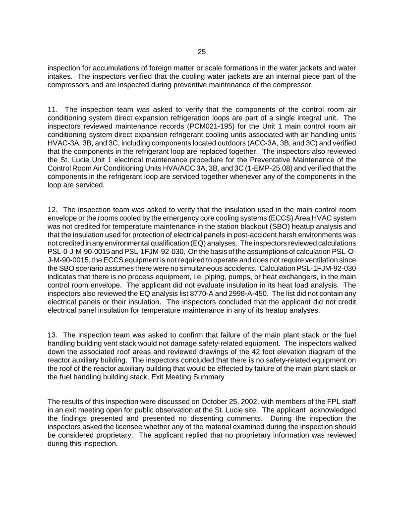
25
inspection for accumulations of foreign matter or scale formations in the water jackets and waterintakes. The inspectors verified that the cooling water jackets are an internal piece part of thecompressors and are inspected during preventive maintenance of the compressor.
11. The inspection team was asked to verify that the components of the control room airconditioning system direct expansion refrigeration loops are part of a single integral unit. Theinspectors reviewed maintenance records (PCM021-195) for the Unit 1 main control room airconditioning system direct expansion refrigerant cooling units associated with air handling unitsHVAC-3A, 3B, and 3C, including components located outdoors (ACC-3A, 3B, and 3C) and verifiedthat the components in the refrigerant loop are replaced together. The inspectors also reviewedthe St. Lucie Unit 1 electrical maintenance procedure for the Preventative Maintenance of theControl Room Air Conditioning Units HVA/ACC 3A, 3B, and 3C (1-EMP-25.08) and verified that thecomponents in the refrigerant loop are serviced together whenever any of the components in theloop are serviced.
12. The inspection team was asked to verify that the insulation used in the main control roomenvelope or the rooms cooled by the emergency core cooling systems (ECCS) Area HVAC systemwas not credited for temperature maintenance in the station blackout (SBO) heatup analysis andthat the insulation used for protection of electrical panels in post-accident harsh environments wasnot credited in any environmental qualification (EQ) analyses. The inspectors reviewed calculationsPSL-0-J-M-90-0015 and PSL-1FJM-92-030. On the basis of the assumptions of calculation PSL-O-J-M-90-0015, the ECCS equipment is not required to operate and does not require ventilation sincethe SBO scenario assumes there were no simultaneous accidents. Calculation PSL-1FJM-92-030indicates that there is no process equipment, i.e. piping, pumps, or heat exchangers, in the maincontrol room envelope. The applicant did not evaluate insulation in its heat load analysis. Theinspectors also reviewed the EQ analysis list 8770-A and 2998-A-450. The list did not contain anyelectrical panels or their insulation. The inspectors concluded that the applicant did not creditelectrical panel insulation for temperature maintenance in any of its heatup analyses.
13. The inspection team was asked to confirm that failure of the main plant stack or the fuelhandling building vent stack would not damage safety-related equipment. The inspectors walkeddown the associated roof areas and reviewed drawings of the 42 foot elevation diagram of thereactor auxiliary building. The inspectors concluded that there is no safety-related equipment onthe roof of the reactor auxiliary building that would be effected by failure of the main plant stack orthe fuel handling building stack. Exit Meeting Summary
The results of this inspection were discussed on October 25, 2002, with members of the FPL staffin an exit meeting open for public observation at the St. Lucie site. The applicant acknowledgedthe findings presented and presented no dissenting comments. During the inspection theinspectors asked the licensee whether any of the material examined during the inspection shouldbe considered proprietary. The applicant replied that no proprietary information was reviewedduring this inspection.
26
ATTACHMENT 1
SUPPLEMENTAL INFORMATION
PARTIAL LIST OF PERSONS CONTACTED
Applicant
T. Abbatiello License Renewal Environmental Lead
B. Beisler, License Renewal Civil Lead
R. Curtis, President IBEW LU 627
K. Getty, Sr. QA Engineer
S. Hale, FPL License Renewal Manager
D. Jernigan, Site Vice President
D. Joy, License Renewal Mechanical Lead
F. Prieto, License Renewal Electrical/I&C Lead
T. Menocal, License Renewal Technical Lead
H. Onorato, License Renewal Design Basis
R. Scott, Nuclear Communications Manager
V. Spencer, FPL Energy Encounter
NRC
K. Corp, NRR Staff Member
H. Christensen, Deputy Division Director
K. Clark, NRC Sr. Public Affairs Officer
N. Dudley, Sr. Project Manager, NRR
T. Ross, Senior Resident Inspector
Public
N. Deajon, TV News 12
E. Modzelewski, Fort Pierce Tribune
F. Porter, Photographer, TV New 12
J. Roberts, WQCS Radio
D. Sells, Florida Municipal Power Authority

27
LIST OF DOCUMENTS REVIEWED
Engineering Documents
PSL-ENG-LRNS-02-020, Resolution of Scoping Issue Regarding Non-Safety-Related PipingInteractions with Safety-Related Components for St. Lucie Units 1 and 2 License RenewalApplication, Rev. 2
PSL-ENG-LRSP-00-030, License Renewal System/Structure Scoping Report St. Lucie Unit 1, Rev.4
PSL-ENG-LRSP-00-031, License Renewal System/Structure Scoping Report St. Lucie Unit 2, Rev.3
PSL-ENG-LRSC-00-050, “St Lucie Units 1&2 License Renewal Screening Results - Structures andStructural Components,” Rev. 3, 9/20/02 and Rev. 4, 10/24/02
PSL-ENG-LRSC-00-052, License Renewal Screening Results for Electrical/I&C ComponentCommodity Groups, Rev. 2.
ENG-QI 5.3, License Renewal System/Structure Scoping Report, Rev. 4
ENG-QI 5.4, License Renewal Screening, Rev. 3,
DBD-SLI-IFLO-1, Design Basis Document for Internal Flooding Criteria, Rev. 1
PSL-0-J-M-90-0015, St. Lucie Units 1 and 2 Station Blackout Safe Shutdown Equipment, Rev. 4
Condition Report 01-1081, Containment coatings closeout inspection (required per Spec -C-034)performed on 4/20/01.
Licensing Documents
Application For Renewed Operating License - St. Lucie Nuclear Plant Units 1 & 2
FP&L Letter, L-2002-157, dated September 26, 2002
FP&L letter L-2002-166, dated September 26, 2002
St. Lucie Unit 1 Updated Final Safety Analysis Report, Amendment 18
St. Lucie Unit 2 Updated Final Safety Analysis Report, Amendment 13
PSL-ENG-LRAM-00-0084, License Renewal Aging Management Review - Diesel Generator AirSystem, Rev. 2
License Renewal Screening Results Summary Reports
PSL-ENG-LRSC-00-033, Reactor Coolant & Control Element Drive Mechanism Systems, Rev. 3
PSL-ENG-LRSC-00-043, Chemical and Volume Control System, Rev. 4

28
PSL-ENG-LRSC-00-040, Containment Spray System, Rev. 3
PSL-ENG-LRSC-00-042, Safety Injection System, Rev. 2
PSL-ENG-LRSC-00-034, Primary Makeup Water System, Rev. 4
PSL-ENG-LRSC-00-032, Intake Cooling Water, Rev. 3
PSL-ENG-LRSC-00-036, Component Cooling Water, Rev. 4
PSL-ENG-LRSC-00-041, Fire Protection System, Rev. 5
PSL-ENG-LRSC-00-046, Fuel Pool System, Rev. 2
PSL-ENG-LRSC-00-047, Instrument Air and Miscellaneous Gas Systems, Rev. 3
PSL-ENG-LRSC-00-049, Turbine Cooling Water, Rev. 1
PSL-ENG-LRSC-00-0035, Unit 1&2 - Main Feedwater System, Rev.3
PSL-ENG-LRSC-00-0045, Unit 1&2 - Diesel Generator System, Rev. 3
PSL-ENG-LRSC-00-0037, Unit 1&2 - Waste Management System, Rev 3
PSL-ENG-LRSC-00-0044, Unit 1&2 - Auxiliary Feedwater System, Rev. 3
PSL-ENG-LRSC-00-0048, Unit 1&2 - HVAC Plumbing Drainage/Leak Detection System, Rev. 3
PSL-ENG-LRSC-00-0038, Unit 1&2 - Miscellaneous Systems, Rev. 2
License Renewal Boundary Drawings
Reactor Coolant, 1/2-RCS-01 through 06, 2-RCS-07 through 09
Chemical and Volume Control, 1/2-CVCS-01 through 04
Containment Spray, 1/2-CS-01 & 02
Safety Injection, 1/2-SI-01 through 04
Instrument Air, 1/2-IA-01 through 05 and 1-IA-06
Component Cooling Water, 1/2-CCW-01 through 3
Intake Cooling Water, 1/2-ICW-01 & 02
Turbine Cooling Water, 1/2-TCW-01
Spent Fuel Pool, 1/2-SFP-01
Diesel Generators and Support Systems,1/2-EDG-01 through 07
Sampling, Containment Post Accident Monitoring, 1/2-SAMP-01 through 03
Ventilation, 1/2-HVAC-01 through 03
Waste Management, 1/2-WM-01 through 03
Main Feedwater and Steam Generator Blowdown,1/2-FW-01 through 02, 1/2-SGBD-01
Auxiliary Feedwater and Condensate, 1/2-AFW-01 through 02

29
Primary Water, 1/2-PW-01 and 2-PW-02
Fire Protection, 1-FP-01 through 1-FP-05, 2-FP-01and 2-FP-02
Plant Drawings
FP&L drawing 3509-G-117, Flow Diagram, Steam Generator Blowdown Miscellaneous Systems,Rev. 21
EBASCO drawing W8020821, Schematic for Anchor/Darling Self-contained Hydraulic Actuator,Non-redundant, (Main Feedwater Isolation valve) Rev. F
Terry drawing 103392D, Terry Turbine Schematic - Oil Piping, Rev.8
8770-13348, Steam Generator General Arrangement, Rev. 1
8770-13217, Feedwater Header Pipe, Rev. 0
8770-13216, Feedwater Header Pipe (Ordering), Rev. 0
8770-13281, Support Ring Slotting, Rev. 0
2998-16330, Feedwater Piping Details Steam Generator, Rev. 1
2998-G-084, Sheets 1 & 2; Flow Diagram Domestic and Make-Up Water Systems; Rev. 33
8770-G-084, Sheets 1A, 1B, & 1C; Flow Diagram Fire Water, Domestic, and Make-Up Systems;Rev. 44
8770-G-079, Sheets 3 & 4; Flow Diagram Extraction Steam System; Rev. 31
2998-G-079, Sheets 3 & 4; Flow Diagram Extraction Steam System; Rev. 20
8770-G-862, HVAC-Air Flow Diagram, Rev. 28
8770-G-879, HVAC-Control Diagrams-Sheet 2, Rev. 34
Plant Procedures
Specification No. SPEC–034, Protective Coatings for Service Level I Applications Inside ReactorContainment Building, Rev. 2.
1-ONP-100.01, St. Lucie Unit 1, Response to Fire, Rev. 14B
2-1800023, Unit 2 Fire Fighting Strategies, Section K-32, Rev. 23
Design Basis Documents
DBD-HVAC-1/2, Safety Related HVAC Systems, Rev. 0
DBD-C/F-1/2, Condensate and Feedwater System, Rev. 0

30
DBD-AFW-1/2, Auxiliary Feedwater System, Rev. 0
DBD-EDG-1/2, Emergency Diesel Generator System, Rev. 0
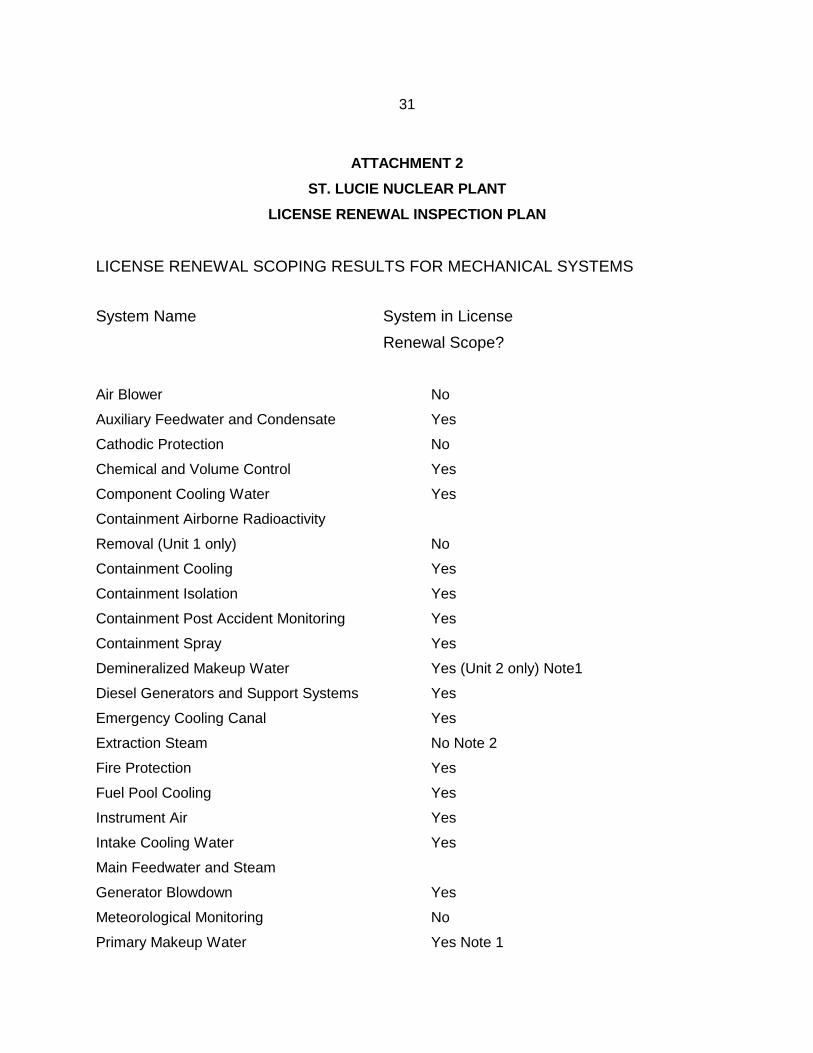
31
ATTACHMENT 2
ST. LUCIE NUCLEAR PLANT
LICENSE RENEWAL INSPECTION PLAN
LICENSE RENEWAL SCOPING RESULTS FOR MECHANICAL SYSTEMS
System Name System in License
Renewal Scope?
Air Blower No
Auxiliary Feedwater and Condensate Yes
Cathodic Protection No
Chemical and Volume Control Yes
Component Cooling Water Yes
Containment Airborne Radioactivity
Removal (Unit 1 only) No
Containment Cooling Yes
Containment Isolation Yes
Containment Post Accident Monitoring Yes
Containment Spray Yes
Demineralized Makeup Water Yes (Unit 2 only) Note1
Diesel Generators and Support Systems Yes
Emergency Cooling Canal Yes
Extraction Steam No Note 2
Fire Protection Yes
Fuel Pool Cooling Yes
Instrument Air Yes
Intake Cooling Water Yes
Main Feedwater and Steam
Generator Blowdown Yes
Meteorological Monitoring No
Primary Makeup Water Yes Note 1

32
Reactor Coolant Yes
Safety Injection Yes
Sampling Yes Note 1
Service Water Yes Note 1
Turbine Cooling Water Yes (Unit 1 only) Note 1
Ventilation Yes
Waste Management Yes Note 1
NOTES: 1. Although this system is not evaluated in the GALL Report, it was determined toperform a system intended function that satisfies the scoping criteria of 10 CFR 54.4(a).
2. Although this system is evaluated in the GALL Report, it was determined to not performa system intended function that satisfies the scoping criteria of 10 CFR 54.4(a) and thusis not within the scope of license renewal.

33
ST. LUCIE NUCLEAR PLANT
LICENSE RENEWAL INSPECTION PLAN
LICENSE RENEWAL SCOPING RESULTS FOR STRUCTURES
System Name Structure in License
Renewal Scope?
Component Cooling Water Areas Yes
Condensate Storage Tank Enclosures Yes
Containments Yes
Diesel Oil Equipment Enclosures Yes
Emergency Diesel Generator Buildings Yes
Fire House No
Fire Rated Assemblies Yes
Fuel Handling Buildings Yes
Fuel Handling Equipment Yes
Intake and Discharge Pipelines No
Intake, Discharge, and Emergency
Cooling Canals Yes
Intake Structures Yes
Intake Velocity Caps No
Reactor Auxiliary Buildings Yes
St. Lucie and Hutchinson Island Substations No
Steam Trestle Areas Yes
Switchyard No
Turbine Buildings Yes
Ultimate Heat Sink Dam Yes
Yard Structures Yes

34
ST. LUCIE NUCLEAR PLANT
LICENSE RENEWAL INSPECTION PLAN
LICENSE RENEWAL SCOPING RESULTS FOR ELECTRICAL/I&C SYSTEMS
System Name System in License
Renewal Scope?
120/208V Electrical Yes
120V Vital AC Yes
125V DC Yes
4.16kV Electrical Yes
480V Electrical Yes
6.9kV Electrical Yes
Communications Yes
Computer Process and Reactivity No
Containment Electrical Penetrations
(conductor, non-metallic,
and non-pressure boundary portions) Yes
Data Acquisition Remote Terminal Unit Yes
Generation and Distribution
(includes Main, Auxiliary, and Start-up
Transformers and the Switchyard) No
Miscellaneous (includes EQ commodities) Yes
Nuclear Instrumentation Yes
Reactor Protection Yes
Safeguards Panels Yes
Station Grounding Yes

35
ATTACHMENT 3
LIST OF ACRONYMS USED
ADV Atmospheric Dump Valves
AFW Auxiliary Feedwater System
AMR Aging Management Review
CC Containment Cooling
CCW Component Cooling Water
CCWA Component Cooling Water Areas
CP Cathodic Protection System
CR Condition Report
CS Containment Spray System
CST Condensate Storage Tank
CVCS Chemical and Volume Control System
ECC Emergency Cooling Canal
ECCS Emergency Core Cooling Systems
EDG Emergency Diesel Generator
EQ Environmental Qualification Program
FPL Florida Power and Light Company
HVAC Heating Ventilation and Air Conditioning
IA Instrument Air
ICW Intake Cooling Water System
ILRT Integrate Leak Rate Test
LLRT Local Leak Rate Test
LR License Renewal
LRA License Renewal Application
NSR Non Safety Related
NRR NRC Office of Nuclear Reactor Regulation
RAB Reactor Auxiliary Building
RAI Request for Additional Information
RCS Reactor Coolant System
RCSB Reactor Containment Shield Building
RV Reactor Vessel

36
RWT Refueling Water Tank
SBO Station Blackout Event
SCV Steel Containment Vessel
SFPC Spent Fuel Pool Cooling System
SGOBD Steam Generator Open Blowdown System
SI Safety Injection
SR Safety Related
SSC Systems, Structures, and Components
SSMP Systems and Structures Monitoring Program
SW Service Water System
TCW Turbine Cooling Water
UFSAR Updated Final Safety Analysis Report