florida state university department of computer · pdf fileflorida state university department...
TRANSCRIPT

Florida State University
Department of Computer Science
Knowledge Base for Intrusion Detection System -Nikhil M Patel
Project submitted to Department of Computer Science
in partial fulfillment of the requirements for the
Master of Science degree (M.S)

2
Acknowledgements
I would like to thank my advisor Dr. Alec Yasinsac, who mentored me during the
completion of this project; it would not have been possible to finish this project without
his help and guidance. I would also like to thank my team members, Sachin Goregaoker
and Alex Melendez for their support. Lastly I would like to dedicate this project to my
parents, who have been my guiding light.

3
Table of Contents Knowledge Base for Intrusion Detection System ............................................................... 1 1 Introduction ...................................................................................................................... 4
1.1 Security Protocols ..................................................................................................... 4 1.2 Overview of Detecting Intrusions in secure environment......................................... 5 1.3 SEADS ...................................................................................................................... 5
2 Intrusion Detection........................................................................................................... 6
2.1 Behavior Based Detection......................................................................................... 7 2.1.1 Models used in behavior based detection........................................................... 7
2.2 Knowledge based intrusion detection ....................................................................... 8 2.2.1 Models used in knowledge based detection ....................................................... 9
3 Scope of Project ............................................................................................................... 9
3.1 Role of Knowledge Base in SEADS....................................................................... 10 3.2 Functionality of Knowledge Base ........................................................................... 11
4 Attack Detection Methodology ...................................................................................... 12
4.1 Forming Signatures of Attack ................................................................................. 12 4.2 Signature representation.......................................................................................... 16
4.2.1 Signature Format .............................................................................................. 17 4.3 Finite State Machine Representation Of Signature ................................................. 19 4.4 Classification Of Attacks ........................................................................................ 20
4.4.1 Single Session Attacks ..................................................................................... 20 4.4.2 Multiple Session Attacks.................................................................................. 21
5 Design Of Knowledge Base ........................................................................................... 23
5.1 Identifying The Operations ..................................................................................... 23 5.2 Signature Formation In Knowledge Base ............................................................... 24 5.3 Module Explosion ................................................................................................... 26
6 Testing............................................................................................................................ 30 7 Conclusions .................................................................................................................... 31 8 Appendix ........................................................................................................................ 32

4
1 Introduction With security of communication on the Internet becoming an important issue, the need
for an intrusion detection system becomes inherent. This need is heightened in the case of
high assurance data being put on the communication channel. Presently secure
communication uses cryptography to provide security and integrity of data, but in order
to do so communicating parties have to follow security protocols to establish
communication. In such an environment detecting intrusion without looking into the
payload of the message is a novel idea, as many of the systems presently used in industry
detect attacks by analyzing the payload of the message.
The idea of attack detection by using meta- information about the packets on the network
was introduced in [1]. The author details three components of such a system: The
Monitor, the Intrusion Detection Engine and the Knowledge Base. This project
implements the knowledge base and designs the signature that can be used in an intrusion
detection system operating in an environment that uses security protocols to establish the
communication between the involved parties.
1.1 Security Protocols
Protocols are rules that govern interactions between communicating parties.
Authentication, the act of determining the identity of a principal, is a basic necessity of
any security system. Because of this, and because of its complexity and potential for
error, authentication methods have been topic of intense research.
Research in authentication protocols is aimed at identifying potential threats to
authentication and to devising interaction that cannot be broken, i.e., that the successful

5
execution of the authentication protocol does indeed provide strong evidence as to the
identity of the subject(s). “Cryptography is very useful for this purpose”. There is no
doubt that the introduction of keys into cryptographic systems was a revolutionary
change that gave cryptographers a decided advantage over the intruders, at least for a
while. It also introduced the problem of key distribution into cryptographic systems.
Security protocols are aimed at solving the problem of key distribution.
Even security protocols that look relatively straightforward have subtle flaws, which a
sophisticated intruder can exploit in order to defeat the protocol and compromise the
security. This led to the idea of intrusion detection in secure environments, which is
described next.
1.2 Overview of Detecting Intrusions in secure environment
A secure environment can be described as an enclave where trusted parties communicate
with each other with the use of cryptography enabled by security protocols. The
communication channel itself may not be secure and an intruder may be able to exploit
the channel for malicious purposes. A model described in [7] shows the way to develop
intrusion detection system for such an environment. “Secure Enclave Attack Detection
System”, described in next section uses the same model.
1.3 SEADS
“SEADS” is an acronym for “Secure Enclave Attack Detection System” SEADS has
three major components to it viz: -

6
i) Monitor
ii) Detection Engine
iii) Knowledge Base
The roles played by these components in implementation of SEADS are described in
the subsequent sections, with detailed explanation of their functionality. Knowledge
Base is the focus of this project.
2 Intrusion Detection Intrusion detection technology has been an area of intense research over past few years.
Due to this research various methodologies have been suggested. Denning gives an
outline for the model that can be used for intrusion detection in [4]. “Common Intrusion
Detection Framework” (CIDF), which suggests the use of monitor, knowledge base and a
detection engine described in [7]. This model is used to develop the idea of SEADS.
Based on the type of detection methodology used, the knowledge base can contain
various types of information, which is described next. Generic detection techniques can
be classified into either
•= Behavior based detection.
Or
•= Knowledge based detection.

7
2.1 Behavior Based Detection
The behavior based detection technique focuses on characteristics of normal network
traffic and normal user behavior in the target environment. Historical data is tracked and
modeled by statistical measures to establish profiles, which form a baseline against which
to compare new activities. The system beacons when it finds abnormal activity on the
network that is not listed in the profile.
2.1.1 Models used in behavior based detection
The following models are commonly employed for detection of attacks:
a) Statistical Modeling
b) Expert Systems
c) Neural Networks.
Statistical Modeling
This model is widely used for behavior based detection systems. The system gathers user
activities over a period of time and stores them as the user profiles. The period is not
fixed and can vary from just a few hours to months. The idea is to gather a
comprehensive set of user activities, so that the user profile correctly represents “normal”
user behavior. Some common parameters may include login frequency, commands being
regularly issued by the user, resource consumption, etc. The system then monitors the
activity of this user and beacons when it finds something that is not listed in the profile.

8
Expert Systems
Denning has described a prototype of such a system in [4]. This prototype monitors the
target system by comparing the audit records generated by the target environment to its
store of profiles. These profiles are always changing and reflect the user behavior closely.
The profiles themselves are dynamic and the expert system adapts to these changes.
Neural Networks
Intelligent systems are the latest addition to the methodology of intrusion detection.
These systems are still in the developmental stages and few instances are listed in the
literature. The idea behind this concept is that the system can be trained to deduce the
normal behavior of the user so it can easily identify if any malicious activities are taking
place in the target environment. However, this technique is computationally intensive and
is not widely used.
2.2 Knowledge based intrusion detection
In knowledge based approach, the intrusion detection system (IDS) accumulates bad
actor signatures and monitors the target environment for the pre-defined malicious
activities listed in the knowledge base, in the form of signatures. Knowledge-based
systems beacon when they recognize activity that is in their knowledge base. It is also
sometimes termed as misuse detection or detection by appearance, as the detection
methodology is based on matching the events of the network with the events listed in the
knowledge base.

9
2.2.1 Models used in knowledge based detection
2.2.1.1 Finite State Machines
The signature can be represented as a finite state machine. As a result, the detection
engine can spawn a finite state machine every time a new user wants to communicate and
keep track of all the events that take place between the user and other parties involved in
the communication. As soon as any of the finite state machines that were spawned by the
system reaches the final state the system can beacon an attack. This is the method
adopted in this project.
2.2.1.2 Colored Petri Nets
Another way of representing signatures of attacks on encrypted traffic is by the use of
Petri Nets. Petri Nets depict the signature in a graphical form, which makes representing
complex signatures easy and lucid. Petri Nets offer the advantage when it comes to
representing signatures in a generic manner.
3 Scope of Project The intrusion detection system implemented uses knowledge-based detection
methodology to detect attacks in a secure enclave. The following sections describe the
role of knowledge base in SEADS, as well as the constraints and assumptions used to
implement the knowledge base.

10
3.1 Role of Knowledge Base in SEADS
Secure Enclave Attack Detection system is based on the CIDF model [7]. It detects
attacks in real time in the secure environment that uses security protocols to establish the
keys between the communicating parties. SEADS uses meta-information of the packet on
the network and dynamically analyzes the ongoing activity with the knowledge base to
determine the nature of activity, legal or malicious. In order to do so, SEADS utilizes the
signatures represented in the knowledge base, so the knowledge base a crucial component
of the system. Figure1 is a model of the SEADS. It reflects the interaction of knowledge
base with other the components of SEADS.
Intruder
AA
B
C
S
Monitor
IDE
Knowledge base
Figure 1: SEADS

11
Figure 1 shows the three components of SEADS, namely,
1. Monitor: - The principals of the enclave communicate with the monitor,
informing it of all the messages exchanged between the parties involved. In a way
monitor keeps track of the activities going on in the network. The monitor passes
on this information to the detection engine.
2. Detection Engine: - The detection engine checks the sequence of events it
receives from the monitor with the sequence listed in the knowledge base. If a
match is found, the detection engine raises an alert for an attack. So the detection
engine has to interact with the monitor and the knowledge base.
3. Knowledge Base: - The knowledge base has record of all the protocol signatures
being executed in the enclave. Based on these signatures, the detection engine
analyzes the network activity to detect attacks on the protocols.
3.2 Functionality of Knowledge Base
The knowledge base is like a database of signatures, so it has to have functional
capability of any other database. Among its tasks we must be able to:
a. Add signatures to the database.
b. Delete signatures from the database.
c. Modify the existing signatures from the database.
d. Read existing signatures.
Apart from this, it was found during the research that there has to be a provision for
adding protocol ids, which is described in the later section and provision to regulate
access to valid users only. Therefore, these capabilities are also added to the above set:
a. Add protocol id to the database.
b. Provide password protection.

12
c. Since the user must enter the signature manually, above functionality needs a
neat user interface to manipulate the signatures. A Graphical User Interface
(GUI) is provided to achieve this purpose.
d. The knowledge base has to interface with the IDE, so the database is
represented as a “Flat File”. The use of flat file structure is done to provide a
simple Application Program Interface (API) to the IDE.
4 Attack Detection Methodology The intrusion detection system developed is knowledge based detection system; that is it
looks up the sequence of malicious activities for the protocol being executed from the
knowledge base and compares them with the sequence occurring in the monitored
network. As described section 2.2.1 finite state machine analysis technique is used to
detect attacks. The signatures are represented as finite state machines in this approach of
attack detection.
4.1 Forming Signatures of Attack
Signatures of attack have to be derived from the protocol description. The IDS does not
depend upon the payload information of the messages exchanged between principals
during protocol sessions. It rather uses the meta-information of the packet to analyses the
possibility of attack.
As an example, consider famous security protocol called Needham and Schroeder
Conventional Key Protocol (NSCKP) described in [5]. This protocol has three principals:
A, B and S, where S is a trusted third party server S. The protocol is used to establish a

13
secret key Kab that is to be used by the principals A and B to encrypt their future
exchanges.
The protocol in discussion is as follows:
1) A � S : A, B, Na
2) S � A : E(Kas: Na, B, Kab, E(Kbs : Kab, A))
3) A � B : E(Kbs : Kab, A)
4) B � A : E(Kab : Nb)
5) A � B : E(Kab : Nb-1)
The stepwise explanation of the above protocol is given below.
Step1: Principal A requests trusted server S for a key to be used for secure
communication with principal B. The message that A sends to the server S is shown
above after “:” includes the name of the sending and the receiving principal and a random
number generated by A called nonce Na, used to know the freshness of message.
Step 2: This is most important step wherein server S on receiving the request generates
the message to be sent to principal A which contains the requested key Kab (shared by A
and B only). The message that S sends to A is encrypted by the key, which S shares with
A, so that only A can decrypt the message. The message generated here contains the
secret key that A and B would be using for exchanging messages among themselves.
Step 3: On receiving the message from S, A decrypts it with the key it shares with S and
sends the part of the message encrypted with key Kab to B. This way B would also come
to know the key it would be sharing for the communication with A.

14
At the end of protocol both the parties A and B are sure that they are communicating with
the intended parties and not anyone else. The protocol achieves the purpose of
authentication and integrity.
However the intrusion detection system does not use all the information the protocol
provides about the encryption and hence in the representation of the protocol for the
intrusion detection system, all that information can be stripped off. Thus the protocol can
be represented by send and receive events is as shown below:
1) A � S 6) B ���� A
2) S ���� A 7) B � A
3) S � A 8) B ���� A
4) A ���� S 9) A � B
5) A � B 10) B ���� A
The above signature has ten steps instead of 5, which were in the original protocol, the
reason being that each step in the original protocol has a send event only, the signature
represented above has a receive event for every send event.
Steps 2, 4, 6, 8 and 10 represent the receive event which are not listed in the protocol but
are taken to be implicit operations.
Each step of the protocol is called an event. There are two types of events, namely send
and receive. Whenever a principal executes any of the two events it informs the monitor
about the event. Thus the monitor knows exactly what each principal is doing at any
given time. But the exchange of the messages between the principals take place on an
insecure network channel so there is a possibility of lost messages, in which case the

15
monitor will not know whether the send event was completed, so it becomes necessary to
include a receive event.
The protocol just described is a normal or the legitimate run of the protocol. Although it
looks straightforward, it nevertheless has subtle flaws that can be exploited by the
intruder for malicious purposes. Illustration of one such attack is given in [6].
Consider step 3 of the above protocol. Although B decrypts this message and assumes
legitimately that is created by the server S, there is nothing in the message to indicate that
the message was actually created by S as a part of current run of protocol.
Suppose that the intruder Z was monitoring the network and has got hold of a previously
distributed key K’ab, and is able to break it (say by cryptanalysis). Now Z can fool B into
accepting the key as a legitimate key for the current run of protocol in following manner:
3) Z(A) � B : E(Kbs: K’ab, A)
4) B � Z(A) : E( K’ab: Nb)
5) Z(A) � B : E(K’ab: Nb –1)
Note: Z(A) means Z masquerading as A.
Now, at the end of the protocol B believes that A is the other party in session. Thus the
protocol is attacked.
The signature that can detect the above attack is shown below.
1) B � A
2) B � A
3) B � A

16
The above signature comprises of only three events, two receives and a send event. Since
the malicious intruder is not the part of secure enclave it cannot communicate with the
monitor and so the monitor will not record any send events on the part of intruder, which
is masquerading as A. Thus the above attack signature will consist only of events,
reported by B, to the monitor.
4.2 Signature representation
The IDS implements the knowledge based detection technique. It uses finite state
machine analysis to detect the attack on the security protocol. In this model the signature
is represented as a finite state machine. Therefore, each time IDE receives an event
corresponding to the first event of a new protocol, it looks up in the knowledge base and
constructs a finite state machine corresponding to the signature of the protocol being
executed. Each time IDE receives an event particular to a protocol, it changes the state of
corresponding finite state machine.

17
4.2.1 Signature Format
The signature of a protocol is sequence of events occurring in the protocol. An event as
represented in the knowledge base can either be a send or receive event. The general
representation of event is as shown in figure 2.
Figure 2: Event Representation. All the attributes used in event representation are explained below.
•= Cur_state: Indicates the current state of finite state machine. It also indicates the
state the machine was before the event occurred. (ss: start state, s1: state1..Etc)
•= Principal_1 / Principal_2: Indicates the principals involved in the communication.
(A, B, C…S: Single letter identifier of principals)
•= Send / receive: Indicates the kind of event. (send: “�”, receive: “�”)
•= Next_state: Indicates the state of machine after the event takes place. (fs: final
state, s1: state1…etc.)
•= Message #: Indicates the sequence number of the message being exchanged.
•= Session #: Indicates the session number of the protocol between the
communicating parties. This field is unused as of now in this implementation and
always set to 1. This field may be used in future as needed.
An example of event is shown below:
Cur_State Principal_1 send/receive Principal_2 next_state Message_# Session_#
s3 A � B s4 1 1

18
Now that the structure of event is known, we can represent a signature in a generic
manner as shown in figure 3.
begin Protocol_ID Signature_ID Type
Event # 1
Event #2
:
:
:
Event # n
end
Figure 3: Signature Representation.
The first line of the signature gives information about the protocol for which the signature
is written (Protocol_id), the number of the signature (signature_id) [there can be more
than one attack on a protocol] and the type of attack the signature represents (Type).
Finally let us consider an actual signature of attack on “Needham and Schroeder
Conventional Key Protocol” (NSCKP) discussed in section 4.1.
begin NSCKP 0 S
ss B ���� A s1 1 1
s1 B ���� A s2 2 1
s2 B ���� A fs 3 1
end

19
4.3 Finite State Machine Representation Of Signature
The above signature can be represented as a finite state machine in following way:
Current State Event Next State Message Number
SS B ���� A S1 1
S1 B ���� A S2 2
S2 B ���� A FS 3
We can represent the finite state machine from the above table graphically as shown
below:
The IDE spawns this machine when it gets the first event of the signature of the attack.
Initially, the machine is in the start state “ss”. As the events come, the IDE compares
them with the events in the signature of the attack and advances the machine state
accordingly. When the machine reaches the final state “fs”, the IDE signals an attack on
the protocol. This way all that the IDE has to do is to spawn the finite state machines
corresponding to the signature and keep track of the state of the machine. If any of the
machines corresponding to the protocol reach a final state, an attack can be signaled.
Since there can be more than one attack on a protocol, the number of finite state
machines for a protocol can vary from one to many. But as soon as any of them reach a
final state, the IDE can signal an attack on that protocol. This is true for machines that
represent the attack signatures only, as stated earlier, the knowledge base has the
signature of normal run of protocol in it, so the IDE has to spawn finite state machine for
s1
ss s2
B � A B � A
B � Afs

20
it too. But if that machine reaches final state then it only means that a legitimate session
has executed between the involved parties and the IDE does not signal an attack.
4.4 Classification Of Attacks
In order to aid the successful detection of attacks on protocols, attacks are classified into
categories, these categories are not necessarily the ones followed in literature. It was
found out during research that the categorization followed in literature made it hard for
SEADS to detect all possible attacks on the protocols. Each category has a distinct
characteristic that can be used for detecting an attack. Broadly speaking, the attacks are
classified into two categories:
1. Single session attacks
2. Multiple session attacks
4.4.1 Single Session Attacks
These types of attacks are carried out on current run of the protocol, i.e. they may or may
not use information from the previous session of the protocol, like the secret keys or the
encrypted message itself. The attack on Needham and Schroeder Conventional Key
Protocol described earlier is a canonical example of Replay Attack as listed in the
literature. The attack uses the information that was used in the previous run of the
protocol, this run could have taken place few hours back or a even few years back and the
detection engine would have to keep track of that information. This is not possible in
SEADS, as the concept of infinite memory to store such data is not practical. Thus the
information that is visible to SEADS, which may be couple of sessions old, can be used
for detection purpose. Therefore we have categorized such attacks, which use information
visible in a single session as “Single Session Attacks”. Hence the categorization of attack
on Needham and Schroeder protocol as a Single Session attack. The detection of such
attack is straight forward, in the sense, all that IDE has to do is to follow the finite state
machine for the signature and when that reaches the final state, attack is detected. These
types of attacks are generally carried out on protocols that do not employ timestamps in
the messages to check for the freshness of the message. This is evident from the

21
Needham and Schroeder protocol described earlier. All that it uses to check the freshness
of the message is the randomly generated nuances. This type of attack is listed as a
Replay attack in the literature but according to our categorization, these attacks fall under
single session attacks.
4.4.2 Multiple Session Attacks
These types of attacks are carried out using information from two or more runs of the
same protocol. These attacks are further classified into two categories, based on the
information they use to subvert the protocol.
1. Replay Attacks
2. Parallel Session Attacks
4.4.2.1 Replay Attacks
As the name suggest, these attacks are carried out by replaying information from the
previous run of the same protocol. The information that is replayed has to be fresh, i.e.
the information has to be replayed within a time limit or else it would become invalid.
The time limit for such attacks is generally the longest network delay a packet can suffer
when transmitted from the sender to receiver. This time limit is calculation is described in
[6]. These attacks are carried out on protocols that use timestamps to check the freshness
of the message.
To detect such attacks the IDE would not have to follow the finite state machine
corresponding to the signature but it would also have to keep track of the timing
characteristic of the message. That is the IDE will have to check whether the message
delivered was within the stipulated time period that the protocol uses. If the message
were delivered after the time limit, it would be considered as a suspicious activity. The
IDE will then follow the finite state machine corresponding to the signature of the
protocol and would detect an attack as soon as the machine reaches its final state.
4.4.2.2 Parallel Session Attacks
Parallel session attacks are carried out when two or more runs of the protocols are
executed simultaneously and the information from one run is used in the other run to

22
subvert the protocol. These attacks have the characteristic of the replay attack in them,
i.e. the information being replayed has to be fresh in order to be valid.
Again the detection of such attacks involves monitoring of concurrent sessions of the
same protocol as well as the timing characteristics of the transmitted message. These
attacks are carried out by concurrently initiating a session using the same protocol, with
same principals and then replaying the information from one session in another session.

23
5 Design Of Knowledge Base This section gives complete and comprehensive design of knowledge base. It discusses
the evolution of all the functionality there is to the knowledge base and the design
decisions taken with the justification for them. It highlights the modules, their
functionality and interconnection. The basic functionalities of the knowledge base will be
a good starting point to design the modules.
5.1 Identifying The Operations
From the topmost level, the following operations are performed on the knowledge base:
��Adding signatures.
��Reading signatures.
��Modifying signatures.
��Deleting signatures.
Figure 4 shows these operations schematically.
Figure 4: ADD, READ, UPDATE & DELETE are the basic operations that can be performed on the
knowledge base.
Knowledge Base ADDManual
Operator
READ
MODIFY
DELET
Knowledge Base Manual
Operator
Knowledge Base Manual
Operator
Knowledge Base Manual
Operator

24
From Figure 4, it can be gathered that the knowledge base is designed taking above
operations that it has to support as a design criteria. Representing the above diagram as a
structure chart condenses the entire picture.
Figure 5: Structure Chart
From the above two diagrams it is quite clear that the knowledge base provides for
signature taxonomy which facilitates the four basic operations imperative to its efficient
functionality. This knowledge base pivots around the security protocols. The most
prominent security protocols include Needham Schroeder Protocol, Denning Saco
Protocol and Otway Rees Protocol. The knowledge base is designed to store signatures
for such protocols.
Under each security protocol there may be more than one signature that represent
malicious activity. The knowledge base serves as a repository for these signatures. This
repository refers to a file, which contains all the signatures that are generated from the
input information supplied by the manual operator.
5.2 Signature Formation In Knowledge Base
Figure 6 depicts the Data Flow Diagram for the Knowledge Base. The flow is mapped by
the number increasing monotonically, which determines the flow of data and/or the
execution of each function performed by the knowledge base. The legend explains the
detailed process of signature formation in the knowledge base.
Knowledge Base
ADD Signature
READ Signature
MODIFY
DELETE

25
Figure 6: Data flow diagram.
Signature File
Literature Menu Screen Literature/Experience Literature
Manual Entry for adding
Signature formed from the input.
24
Manual Entry for modifying
5
6
Manual Deletion of
signatures
Signature matched
8
7
Detection Engine
10
3 9
1

26
Legend
Action
Sequence
Related Action
1 Gathering information from literature.
2 Feeding the gathered information as a signature.
3 The signature file is opened only if there are no read
operations on it
4 The signatures can be read from the signature file.
5 This option is used for modifying the existing signature.
6 Access the signature record from the knowledge base and
then update it.
7 A signature is found to be invalid or obsolete.
8 Look for the signature record. If present then go to the next
step. Else inform the manual operator.
9 Delete the signature from the file.
10 The detection engine shall access the signature file for
Starting its recognizers.
This is how a signature evolves in the knowledge base (and finally, may even expire).
But this is not a rigid scenario. For some signatures the highest evolvement may be just
steps 1 – 4.
5.3 Module Explosion
For the basic operations
��ADD a new signature to the knowledge base
��READ signatures from the knowledge base
��UPDATE signatures that are present in the knowledge base
��DELETE signatures present in the knowledge base
Figure 7 shows the detailed module explosion.

27
Figure 7: Module Explosion diagram
1. ADD
1.1 Gather information into a template and get conformation for signature .
1.2 Open the signature file and write the signature into it.
2. READ
2.1 Get the contents of the respective signature and display it in the user interface.
3. MODIFY
3.1 Get the signature ID and the protocol ID from the manual operator.
3.2 Display the corresponding signature contents in editable mode.
4. DELETE
4.1 Get the signature ID and protocol ID form the manual operator.
4.2 Display the corresponding signature Delete the signature.
MODULE EXPLOSION
5. RECOVERY
5.1 Whenever the file is updated a backup copy of the file is created.
Legend
6. INITIALIZE
6.1 Initialize the data members, when the knowledge base is being loaded.
7. MENU
7.1 This module acts as an interface between ADD, DELETE, READ and MODIFY modules.
Decomposition

28
5.4 Functionality Of Modules
1. Add: - This module allows the user to enter the protocol id and the signature into a
temporary buffer. Once this information is entered it waits for the user to confirm
the entry. The signature that is generated is then put in a specific format described
in section 4.2.1.The signature file is checked for write permission and if it has the
write permission it is written into the file.
2. Read: - This module searches the signature based upon the protocol id and the
signature id selected by the user. The matching signature is displayed in the user
interface in non-editable mode.
3. Modify: - This module searches the signature based upon the protocol id and the
signature id selected by the user. The matching signature is displayed in the user
interface in editable mode. The corresponding signature can be updated by
accessing the individual components of the signature. Once the signature is
updated, it is written back into the file.
4. Delete: - Based upon the signature’s unique ID, the signature will be matched. If
such a signature does not exist, then the manual operator will be informed about
the absence of the record. When the signature is matched, the entire signature can
be deleted.
5. Recovery: - Each and every time an ADD, MODIFY or DELETE operation is
done on the knowledge base, a backup file is updated.
6. Initialize: - This module initializes all the needed variables. The control is then
passed to the menu module.
7. Menu: - This module acts as an interface for ADD, DELETE, MODIFY and
READ modules.

29
Module Interaction Diagram
M A I N
I NI T I A L I Z E
M E N U
ADD
READ
DELETE
MODIFY
R E C O V E R Y
Legend
X Y
Y module is called by menu when X terminates.
Interacts or call to the module
The module interaction diagram explains the sequence of calls to themodules. Knowledge base execution starts with a call to the MAINmethod, which creates the objects and calls the INITIALIZE module.Then it calls the MENU module. Once the MENU module startsexecuting, it controls the complete execution of ADD, READ,MODIFY, and DELETE modules. Invocation of methods like ADD isfollowed by RECOVERY module. Once the RECOVERY moduleterminates, execution passes to MENU module. This process continuesuntil the execution of the knowledge base terminates.
Figure 8

30
All the class diagrams for the classes used along with the method associated with them
are given in the appendix section of this report. It gives detailed view of the classes used.
6 Testing The most important part of testing was to check the correctness of the signatures of attack
listed in the knowledge base. This part was accomplished by executing each types of
signature on SEADS. SEADS was able to detect all types of attacks namely, Single
Session, Replay and Parallel Session.
Testing of user interface
•= Add module was tested to add the signature with wrong format. The interface
does not write the signature in the file. It tells the user to change the format
accordingly by popping a dialog box on the screen.
•= Add protocol id module was tested to add protocol ids already present in the
knowledge base. The module does not write the protocol id but tells the user that
there is a protocol id with same id already present in the knowledge base.
•= Read module was tested to read signatures which did not have entries in the
knowledge base by giving false protocol ids. The user is informed that the
signature is not present in the system.
•= Delete modules was tested again to delete the signature not present in the
knowledge base by giving false protocol id. The user is informed that the
signature is not present in the knowledge base.
•= Recovery Module was tested by recovering the signature.txt file continuously and
then the file was checked to see if it was recovered by checking it in the windows
explorer. The file was always recovered.

31
7 Conclusions
I have designed the signature format for the attacks on the security protocols and
implemented the interface needed to manipulate the signatures in the knowledge base.
The interface aids the user in entering the signatures in an efficient and error free way.
Extensive research on different attack types and their characteristics led to the
development of the knowledge base and the signatures present in it. The characterization
of attacks into different categories aided the detection of almost all the attacks listed in
the literature.
Since the signatures have to be entered in a specific format, it would have been
cumbersome and error-prone procedure for the user without the interface provided. The
interface makes it easy for a layperson to enter, read and manipulate the signatures once
provided with the format.

32
8 Appendix
A. Resources Used
The project was developed in the Windows network environment, using
Microsoft Visual C++ 6.0. All code was written in C++. The Microsoft
Foundation Classes were used to code the Graphical User Interface.
B. Lessons from this project
It was because of this project that my interest in network security grew, I was able
to enhance my knowledge of security protocols and understand the subtleties
involved in an attack on security protocols.
In implementing the knowledge base, I was able to learn a lot about the Visual
C++ development environment and was able to appreciate the Foundation Classes
provided by Microsoft for graphical user interface programming.

33
C. Class Diagram
SEADS_Signature Class
String Protocol_ID // Stores protocol_ID for the given signature.
Integer Signature_ID //Identification of signatures for each protocol.
String Signature_Buffer //Stores entire signature before updating in file.
File signature.txt //File which consists of all signatures.
Vector[] Num_of_Signatures //Vector consisting of # of signatures.
Vector[] Protocol_Name //Vector consisting of all protocol names.
Void ADD_Generate_Signature()
Void ADD_Write_Signature()
Bool READ_Find_Signature()
Bool MODIFY_Match_Signature ()
Bool MODIFY_Modify_Signature ()
Bool DELETE_Match_Signature()
Bool DELETE_delete_Signature()
Void RECOVERY_Copy_To_Backup_File()
Void INITIALIZE_Defaults()
Void MENU()
34
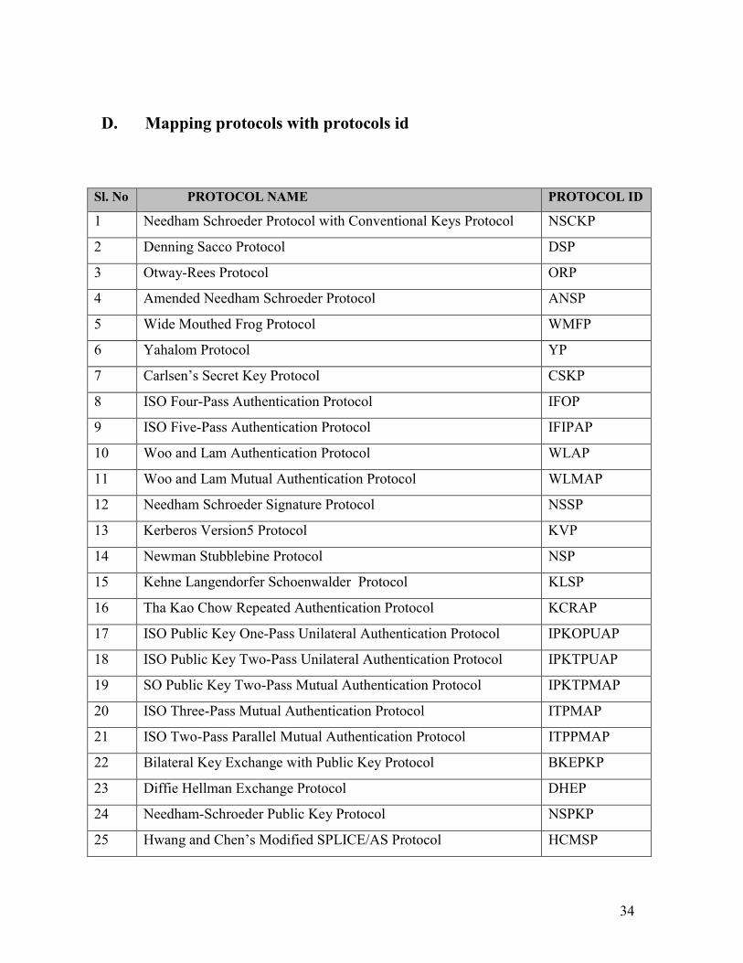
Sl. No PROTOCOL NAME PROTOCOL ID
1 Needham Schroeder Protocol with Conventional Keys Protocol NSCKP
2 Denning Sacco Protocol DSP
3 Otway-Rees Protocol ORP
4 Amended Needham Schroeder Protocol ANSP
5 Wide Mouthed Frog Protocol WMFP
6 Yahalom Protocol YP
7 Carlsen’s Secret Key Protocol CSKP
8 ISO Four-Pass Authentication Protocol IFOP
9 ISO Five-Pass Authentication Protocol IFIPAP
10 Woo and Lam Authentication Protocol WLAP
11 Woo and Lam Mutual Authentication Protocol WLMAP
12 Needham Schroeder Signature Protocol NSSP
13 Kerberos Version5 Protocol KVP
14 Newman Stubblebine Protocol NSP
15 Kehne Langendorfer Schoenwalder Protocol KLSP
16 Tha Kao Chow Repeated Authentication Protocol KCRAP
17 ISO Public Key One-Pass Unilateral Authentication Protocol IPKOPUAP
18 ISO Public Key Two-Pass Unilateral Authentication Protocol IPKTPUAP
19 SO Public Key Two-Pass Mutual Authentication Protocol IPKTPMAP
20 ISO Three-Pass Mutual Authentication Protocol ITPMAP
21 ISO Two-Pass Parallel Mutual Authentication Protocol ITPPMAP
22 Bilateral Key Exchange with Public Key Protocol BKEPKP
23 Diffie Hellman Exchange Protocol DHEP
24 Needham-Schroeder Public Key Protocol NSPKP
25 Hwang and Chen’s Modified SPLICE/AS Protocol HCMSP
D. Mapping protocols with protocols id

35
26 CCITT X.509 Protocol CXP
27 Shamir Rivest Adelman Three Pass Protocol SRATPP
28 Gong Mutual Authentication Protocol GMAP
29 Encrypted Key Exchange –EKE Protocol EKE
30 Davis Swick Private Key Certificates Protocol DSPKCP
31 ISO Symmetric Key One-Pass Unilateral Authentication Protocol ISKOPUAP
32 ISO Symmetric Key Two-Pass Unilateral Authentication Protocol ISKTPUAP
33 ISO Symmetric Key Three-Pass Mutual Authentication Protocol ISKTPMAP
34 Using Non-reversible Functions Protocol UNRFP
35 Andrew Secure RPC Protocol ASRPCP
36 ISO One-Pass Unilateral Authentication with CCFs Protocol IOPUACP
37 ISO Two-Pass Unilateral Authentication with CCFs Protocol ITPUACP
38 ISO Two-Pass Mutual Authentication with CCFs Protocol ITWPMACP
39 ISO Three-Pass Mutual Authentication with CCFs Protocol ITHPMACP
E User Manual and Installation Instructions
This manual is intended for those who are working in SEADS research group and
want to populate the knowledge base with either signatures or protocol activities. The
intended readers should have a little knowledge about the security protocols and their
usage. This manual comes up with a detailed and graphical description of the
knowledge base that makes it easy for the user to understand and use.
1) Installation Instructions
The knowledge base comes with an executable called:
•= KB.exe
The folder first_try has the “KB.exe” stored in Debug folder. The file containing the
signature is called “signature.txt”, all the protocol ids are stored in a file called
“protocol_id.txt”, backup files for both the signature and the protocol ids are stored in
the file “backup_signature.txt” and “backup_protocolid.txt” respectively. These files

36
have to be in the folder where the KB.exe is placed. If these files are moved else
where the application will not execute as it needs to read data from these files.
User can copy all the files from the first_try folder to any other folder and still
execute the Knowledge Base.
2) Explanation of Screens
There are in total 7 screens, this section provides explanation on their usage and
relevancy. Seven screens are:
•= Login Window (Password protected)
•= Main Menu
•= Add Signature
•= Read Signature
•= Delete Signature
•= Modify Signature
•= Add Protocol Id
Login Window
This is the entry point in the program and it regulates the access of knowledge base to
privileged users only. The user has to enter the password inorder to get past this
screen, if the password entered is incorrect the program exits. The password is case
sensitive and is called “seads”. The following screen shot shows the window.
*****

37
Main Menu
Once past the login window, the Main Menu is displayed, this is where all the
functionality of the knowledge base is displayed. The buttons show the operations that
can be performed on the knowledge base by the user. The “Quit” button quits the
application.
“Add Signature” pops the screens where the user can enter a new signature. To add a new
protocol id, the “Add Protocol” button is used, which brings up the screen to add a new
protocol. “Recover the signature file” button is used for recovery of the signature file, this
option is used whenever the file “signature.txt” is corrupted.

38
AddSignature
This screen comes up when Add Protocol button is clicked by the user, the screen
asks the user to enter the protocol id, signature id and all the relevant parts that make
up the signature. The screen makes use of drop down boxes, which are automatically
filled by the application, so all that the user has to do is to select the necessary filed
values and the signature can be created as desired. If for some reason the signature
has errors in it, which the user wants to correct, the editable display on the side can be
used to make changes to the signature.

39
Delete Signature
To delete a signature the user has to choose the protocol id and the signature id of the
signature. There are dropdown boxes to choose these fields. The boxes are filled up
automatically when the screen is displayed to the user. Once the fields are chosen the
signature is displayed in the window, clicking the Delete Signature button pops a
confirm changes box, which asks user whether the signature should really be deleted,
if the user decided against it cancel is clicked the control goes back to the Delete
Signature screen.

40
Read Signature
To read signature from the knowledge base, Read Signature screen is called. User has
to enter the Protocol Id and the Signature Id, which can be chosen from the dropdown
box. Once the fields are selected clicking the Show Signature button displays the
signature on the window.
Add Protocol Id
To add new protocol id in the knowledge bas, Add Protocol Id screen is used. The
user simply has to enter the protocol id in the box, the id is converted to all capital

41
letters and checked for duplication in the protocol id file. If there is already protocol
id present then the user is informed about the duplicates and asked to enter another id.
Modify Signature
To modify an existing signature the Modify Signature screen is used, the user has to
choose the protocol id and the signature id of the signature to be modified from the
dropdown boxes. The corresponding signature is displayed in the editable window. A
signature can then be modified and saved. Once there is any modification done on the
signature the user is asked to confirm the change before the signature is saved. To
cancel the change cancel button can be clicked when the application asks to save
changes in the signature file.

42
Recovery of signatures
This feature is implemented for robustness of the application and to keep SEADS
going on in the event of a loss of the signature file. By clicking the “Recover the
signature file” button, the backup signature file is copied to the original file. The
backup file has the latest changes done to the original signature file.
Clicking Recover button to recover file.

43
8. References
[1] Alec Yasinsac, “Detecting Intrusions in Security Protocols”, Proceedings of first
workshop on Intrusion Detection Systems, in the 7th ACM Conference on Computer
and Communications Security, June 2000, pp.5-8.
[2] John Clark and Jeremy Jacob, “Attacking Authentication Protocols”, High
Integrity Systems, August 1996, pp.465-474.
[3] Dorothy Denning and G.Sacco, “Timestamp in Key Distribution Protocols”,
Communications of ACM, 24(8), August 1981, pp. 533-534.
[4] Dorothy Denning, “An Intrusion Detection Model”, From 1986 IEEE computer
Society Symposium on Research in Security and Privacy.
[5] Roger Needham and Michael Schroeder, “ Using Encryption for Authentication in
Larger Networks of Computers”, Communications of ACM, 21(12), December 1978,
pp. 994-995.
[6] Paul Syverson, “A Taxonomy of Replay Attacks,” Proceedings of the
Computer Security Foundations Workshop VII, Franconia NH, 1994 IEEE CS Press
(Los Alamitos, 1994)
[7] CIDF, Common intrusion detection framework. http://gost.isi.edu/cidf.