flow boiling heat transfer on micro pin fins entrenched in ... · flow boiling heat transfer on...
TRANSCRIPT
1
eepamhmwswaodpho
sdbltn�ttndtbtadmic
N
rS
J
Downloa
Santosh Krishnamurthy
Yoav Peles
Department of Mechanical, Aerospace, andNuclear Engineering,
Rensselaer Polytechnic Institute,Troy, NY 12180
Flow Boiling Heat Transfer onMicro Pin Fins Entrenched in aMicrochannelFlow boiling of 1-methoxyheptafluoropropane (HFE 7000) in 222 �m hydraulic diam-eter channels containing a single row of 24 inline 100 �m pin fins was studied for massfluxes from 350 kg /m2 s to 827 kg /m2 s and wall heat fluxes from 10 W /cm2 to110 W /cm2. Flow visualization revealed the existence of isolated bubbles, bubbles in-teracting, multiple flow, and annular flow. The observed flow patterns were mapped as afunction of the boiling number and the normalized axial distance. The local heat transfercoefficient during subcooled boiling was measured and found to be considerably higherthan the corresponding single-phase flow. Furthermore, a thermal performance evalua-tion comparison with a plain microchannel revealed that the presence of pin fins consid-erably enhanced the heat transfer coefficient. �DOI: 10.1115/1.4000878�
Keywords: micro pin fins, heat transfer coefficient, flow maps
IntroductionThe level of device integration and the clock speed of micro-
lectronic devices have been steadily increasing over the last sev-ral decades. This has resulted in a continuous increase in theower density of electronic devices, giving rise to the need forggressive and effective cooling solutions. The recent develop-ent in microfabrication technology has enabled a new class of
eat sinks for high heat flux applications made of microelectro-echanical system �MEMS� based microchannel. Microchannelsith micro pin fins have been receiving attention because they can
ignificantly enhance the performance of heat sinks comparedith plain microchannels. As a result, a research on flow boiling
nd single-phase flow in micro-pin fin heat sinks has been carriedut by several groups �1–12�. It is well known that heat transferuring subcooled flow boiling can be significantly enhanced com-ared with single-phase liquid flow. However, very limited studiesave been performed to elucidate the heat transfer characteristicsf subcooled boiling in micro pin fin configurations.
In conventional scale, subcooled flow boiling has been exten-ively studied for in-tube systems and various models have beeneveloped to predict the heat transfer rates. These methods can beroadly classified into three categories, namely: empirical corre-ations to predict the wall heat flux �13–17�, empirical correlationso predict the partitioning of wall heat flux �14,18,19�, and mecha-istic correlations for the total heat flux and their partitioning20–22�. Warrier and Dhir �23� provided a detailed review onhese various methods and concluded that mechanistic correla-ions give a better physical insight into subcooled boiling phe-omenon and proposed the use of submodels to define the bubbleynamics. Literature review reveals that boiling in crossflow sys-ems has been extensively studied, but very limited studies haveeen reported in subcooled boiling regime for these configura-ions. Huang and Witte �24,25� studied the effect of liquid flownd high subcooling across a bank of horizontal tube bundles andeveloped a correlation for the heat transfer coefficient using theethodology by Chen �26� developed for saturated nucleate boil-
ng. Shah �27� compared his correlation for heat transfer coeffi-ient around a single-tube, developed for highly subcooled liquid,
Contributed by the Heat Transfer Division of ASME for publication in the JOUR-
AL OF HEAT TRANSFER. Manuscript received November 24, 2008; final manuscripteceived September 30, 2009; published online February 19, 2010. Assoc. Editor:
atish G. Kandlikar.ournal of Heat Transfer Copyright © 20
ded 19 May 2010 to 128.113.217.15. Redistribution subject to ASM
with various correlations developed for low subcooled liquid andfound good agreement. Cornwell �28� studied saturated nucleateflow boiling in tube bundles and attributed the enhancement inheat transfer rates to sliding bubbles. Gupta �29� attributed theenhancement in the heat transfer coefficient during nucleate boil-ing to the turbulence caused by the presence of bubbles on thesurface.
It has been shown that reduction in length scale has a consid-erable affect on the bubble dynamics and flow characteristics dur-ing flow boiling. For subcooled flow boiling this is especiallyimportant since the heat transfer mechanism is very dependent onthe bubble nucleation process. For example, Lee et al. �30� andKuo et al. �31� examined the bubble dynamics for water in amicrochannel and observed considerable differences comparedwith conventional scale systems. Cognata et al. �5� performed avisual study on flow pattern in staggered square micro pin fins andobserved bubbly, slug, and annular flows. Krishnamurthy and Pe-les �3� investigated flow boiling heat transfer of water acrossdensely packed staggered micro pin fins—primarily focusing onsaturated flow boiling—and found that convective boiling was thedominant heat transfer mechanism.
Based on previous studies, it can be concluded that knowledgeabout bubble characteristics in diminishing length scales is impor-tant to elucidate heat transfer mechanisms. In the current manu-script, flow boiling across a single row of inline micro pin finsentrenched in a microchannel is presented. The microdevice con-sists of five 200 �m wide and 243 �m deep microchannels, eachequipped with an inlet orifice, consisting of 24 columns of100 �m diameter circular pin fins, with pitch-to-diameter ratio of4. This study aims to elucidate the local heat transfer coefficient,to identify flow patterns, and to decipher the heat transfer mecha-nisms. Additionally, the performance of the pin fin device wascompared with a plain microchannel device.
2 Device DesignA computer aided design �CAD� schematic of the microdevice,
consisting of five 200 �m wide and 243 �m deep microchannelsentrenched in a 1800 �m wide channel, is shown in Fig. 1. Eachmicrochannel encompassed 24 inline 100 �m diameter micro pinfins with a pitch-to-diameter ratio of 4. Pressure taps were placedat the inlet and the exit of the microchannel array to enable pres-sure measurements. A micro-orifice, 400 �m long and 20 �m
wide, was fabricated upstream of each microchannel to suppressAPRIL 2010, Vol. 132 / 041007-110 by ASME
E license or copyright; see http://www.asme.org/terms/Terms_Use.cfm

flcspdrfl
3
wttd
Ta
U
FVCACCDMAPHLLAARB
a
p
ow
0
Downloa
ow oscillations. A heater was deposited on the backside of thehannel-pin fin section excluding the orifice to provide the requi-ite heat flux. A thermistor 10 �m wide and 300 �m long waslaced 3.33 mm from the channel inlet. A Pyrex cover sealed theevice from the top and allowed flow visualization. For detailsegarding the experimental set up and microfabrication processow, please refer to Ref. �3�.
Data ReductionThe voltage and current were used to calculate the input power,
hile the local temperature from the thermistor was obtained fromhe calibration curve. Assuming 1D steady state conductionhrough the silicon block, the local surface temperature of theevice was obtained by
Tx,s = Tthermistor −�P − Qloss�ts
ksAp�1�
he local quality was calculated from the known mass flow rateccording to
Table 1 Uncertainty of variables
ncertainty variable Measurement range Error
low rate, Q a 0–18 ml/min 2%oltage, V 0–40 V 0.5%urrent, I 0–5 A 0.5%mbient temperature, Tamb NA �1°Channel width, w NA 1%hannel height, H NA 0.67%ensity of liquid, �l NA 0.5%ass flux, G NA 3.4%verage surface temperature, Tr NA �0.5°Cressure, p 0–1379 kPa 3.5 kPaeat flux, qw� NA 3%ocal thermal resistance Rconv NA 12–16%ocal heat transfer coefficient, hx NA 12–16%verage heat transfer coefficient, h NA 10–15%verage Nusselt number, Nu NA 10–15%eynolds number, ReD NA 3.4%oiling number, Bo NA 11%
The manufacturer provided the flow rate range for water, while experiments were
Fig. 1 Device overview sh
erformed with HFE-7000. The flow meter was calibrated prior to experiments.
41007-2 / Vol. 132, APRIL 2010
ded 19 May 2010 to 128.113.217.15. Redistribution subject to ASM
x =�P − Qloss��Lx/Lo� − mcp�Tsat − Ti�
mhfg
�2�
The local heat transfer coefficient for the microchannel with pinfins was calculated according to
Fig. 2 Images showing: „a… isolated bubble region „I…, „b…bubble interacting „BI…, „c… multiple flow region „M…, and „d…
ing the device dimensions
annular flow „A…
Transactions of the ASME
E license or copyright; see http://www.asme.org/terms/Terms_Use.cfm

wt
T
w
twc
J
Downloa
hx =P − Qloss
At�Tx,s − T1��3�
here T1=Tmx if x�0 and T1=Tsat if x�0. The mean local fluidemperature �Tmx� was obtained through an energy balance
Tmx = Tmi + �P − Qloss
mCp
Lx
L� �4�
he total surface area of the channel is given by
At = Nf� fAs,f + Ab + Np�pAs,p �5�
here
� f =tanh�mfH�
mfH, mf =�hx�2�W + L��
ksWL,
�p =tanh�mpH�
mpH, mf =�hx��DH�
ks��D2
4�
The above equations �Eqs. �3� and �5�� were solved iterativelyo obtain the local heat transfer coefficient. Similar methodologyas adopted to obtain the heat transfer coefficient for the plain
Fig. 3 Flow maps based on wall heat flux for all the m=689 kg/m2 s, and „d… G=827 kg/m2 s
hannel, but the total surface area was calculated as
ournal of Heat Transfer
ded 19 May 2010 to 128.113.217.15. Redistribution subject to ASM
At,plain = Nf� fAs,f + At − NfAs,f �6�
The convective resistance used to evaluate the thermal perfor-mance is
Rconv =1
hxAt�7�
The statistical average value of the heat transfer coefficients hxand the corresponding Nusselt numbers over all heat fluxes for afixed Reynolds number in the single-phase region was obtained by
hx =1
M �i=1
M
hx,i �8�
Nux =1
M �i=1
M
Nux,i �9�
The uncertainties associated with the measured values were ob-tained from the manufacturers’ specification sheets �Table 1�while the uncertainties associated with the derived quantities wereobtained by using the propagation of uncertainty analysis, and are
s fluxes: „a… G=350 kg/m2 s, „b… G=564 kg/m2 s, „c… G
asalso given in Table 1.
APRIL 2010, Vol. 132 / 041007-3
E license or copyright; see http://www.asme.org/terms/Terms_Use.cfm

4
pamnritlc2pvpaEawpwssflmwaufctlFt
tdctflvhTw
Fc
0
Downloa
Results and Discussion
4.1 Flow Pattern. In order to determine the dominant flowatterns in the device, images were taken at 10 different locationslong the length of the channel. The flow patterns were thenanually classified into bubbly flow, multiple flow �M�, and an-
ular flow �A�. The bubbly flow was further categorized into twoegions: isolated bubbles �I� and bubbles interacting �BI�. Thesolated bubble region extends over a relatively small section ofhe channel, where bubbles nucleated and departed without coa-escing with bubbles from neighboring sites �Fig. 2�a��. With in-reasing nucleation site density, bubbles began to coalesce �Fig.�b��, and formed larger bubbles with diameter smaller than thein in diameter. Further downstream, these bubbles grew and de-eloped into vapor slugs, which were intermittently sheared by thein fins and broken into bubbles again. This region where bubblesnd vapor slugs coexisted was termed multiple flow �Fig. 2�c��.ventually, the vapor slugs merged and the flow transitioned tonnular flow, where liquid traversed through the channel walls,hile vapor propagated through the core—nucleation was sup-ressed �Fig. 2�d��. In the channel inlet, only liquid single-phaseas present. As expected, for a given mass flux, all flow patterns
hifted upstream with increasing heat flux. Figures 3�a�–3�d�how a flow maps for all mass fluxes as a function of wall heatux and normalized axial distance. The hatch regions on the flowap indicate flow transition regions. Visualization measurementsere repeated three times to obtain a meaningful statistical aver-
ge transition zone. In order to obtain a more general flow mapsing all mass fluxes and heat fluxes, an attempt to collapse theour flow maps into a single map using the boiling number wasarried out. This was done by first plotting the above flow maps inerms of the boiling number and normalized axial distance, fol-owed by fitting the data points with a best curve fit, as shown inig. 4. 90% of the transition data points fell within �12% of the
ransition lines, as shown by the dotted lines in the figure.
4.2 Heat Transfer Coefficient. The local single-phase heatransfer coefficient is shown as a function of the wall heat flux forifferent mass fluxes in Fig. 5�a�. The heat transfer coefficientharacteristics followed similar trend to those observed in conven-ional scale tube bundle systems, i.e., independent of wall heatux and increasing with mass fluxes. Figure 5�b� also shows theariation in the Nusselt number �Nuh�—defined based on channelydraulic diameter—as a function of the Reynolds number �ReD�.he local heat transfer coefficients during boiling as a function of
ig. 4 Flow map showing the different flow patterns along thehannel
all heat flux are shown for different mass fluxes in Figs.
41007-4 / Vol. 132, APRIL 2010
ded 19 May 2010 to 128.113.217.15. Redistribution subject to ASM
6�a�–6�d� �the exit pressure was maintained at 260 kPa�. For G=350 kg /m2 s, the heat transfer coefficient increased linearlywith wall heat flux for qw� �45 W /cm2, and subsequently de-creased. Similar decrease in the heat transfer coefficient was alsoobserved for G=564 kg /m2 s at qw� =80 W /cm2. For mass fluxesof 689 kg /m2 s and 827 kg /m2 s, the heat transfer coefficientincreased linearly with wall heat flux. Figure 7 shows the varia-tion in the heat transfer coefficient as a function of the local qual-ity for the four mass fluxes. The majority of the datum pointscorresponding to two-phase flow are in the subcooled boiling re-gime. Figure 7 also shows that the heat transfer coefficient duringsubcooled boiling is considerably higher compared with thesingle-phase heat transfer coefficient. Such an enhancement dur-ing heat transfer coefficient in nucleate boiling has been observedin both conventional scale channels and minichannels �32,33� andhas been attributed to various mechanisms, such as the evapora-tion of the microlayer beneath a growing bubble, transient con-duction through the cold liquid layer replacing the superheatedliquid layer carried away by the departing bubble �21�, and slidingbubbles �28�. The contribution of these mechanisms are addedlinearly to account for the total heat flux according to �21�
qt� = qev� + qtr� + qsp� �10�
where qt�, qev� , qtr�, and qsp� are the total heat flux, evaporative heat
Fig. 5 „a… The variation in single-phase heat transfer coeffi-cient as a function of wall heat flux and „b… variation in Nusseltnumber as a function of the Reynolds number
flux, quenching heat flux, and single-phase heat flux, respectively.
Transactions of the ASME
E license or copyright; see http://www.asme.org/terms/Terms_Use.cfm

To
5
t
Fl
J
Downloa
he contribution of the above mentioned mechanisms toward thebserved enhancement in the heat transfer is assessed below.
Heat Transfer Enhancement MechanismsEvaporative heat flux. The evaporative heat flux is defined as
he latent energy carried away by the bubbles per unit area and
Fig. 6 Heat transfer coefficients as a function of wall=689 kg/m2 s, and „d… G=827 kg/m2 s
ig. 7 The variation in heat transfer coefficient as a function of2
ocal quality „heat flux in W/cm in parenthesis…ournal of Heat Transfer
ded 19 May 2010 to 128.113.217.15. Redistribution subject to ASM
consists of two terms arising from the stationary and slidingbubbles
qev� = qev,st� + qev,sl� = fVd�vNahfg + f�Vl − Vd��vNahfg �11�
The stationary bubble heat flux is associated with the growth ofthe bubble nucleating on the surface, and the sliding bubble isassociated with the heat transfer during bubble growth while mov-ing along the surface. In Eq. �11�, the bubble departure frequencywas assumed to be equal to the bubble lift off frequency—anassumption that is based on observation of many bubbles. Assum-ing the departing bubble to be spherical, the volume of the depart-ing and lifting bubbles can be calculated as
Vd =�Dd
3
6, Vl =
�Dl3
6�12�
Quenching heat flux. As a bubble departs from a nucleation site,it displaces superheated liquid adjacent to the wall by cold liquidfrom the bulk flow. Han and Griffith �34� postulated that the de-parting bubble carries away with it liquid from an area—termedarea of influence—that is four times the projected area of thedeparting bubble. The quenching heat flux was obtained by fol-lowing the approach adopted by Mikic and Rohsenow �35� assum-ing pure conduction through the liquid in the area of influence.For any stationary bubble departing from the site, the total aver-
at flux: „a… G=350 kg/m2 s, „b… G=564 kg/m2 s, „c… G
heage heat flux over the area of influence is given by
APRIL 2010, Vol. 132 / 041007-5
E license or copyright; see http://www.asme.org/terms/Terms_Use.cfm
Issa
T
limntw
tstbcfcammtr
a
IoswRptdabadnti
33556688
0
Downloa
qtr,st� = 2���k�cp�l fDd2Na�Tw − Tl� �13�
n addition to the stationary bubbles, the bubbles sliding along theurface also displaced the liquid from the surface. Assuming tran-ient conduction through the displaced liquid layer, the total aver-ge heat flux over the area swept by the bubble is given by
qtr,st� = f0
t � k�Tw − Tl����t
AslNa�dt �14�
=2
����k�cp�l fAslNa�Tw − Tl� �15�
he sliding area for the bubbles was obtained as follows:
Asl = Davl =Dd + Dl
2l �16�
is the sliding distance, which was obtained through flow visual-zation. The bubble lift off diameter was found to be approxi-
ately four times the bubble departure diameter for bubblesucleating from the frontal stagnation point �=0 deg� and twicehe bubble departure diameter for bubbles departing from the side-alls.It should be noted that the use of Han and Griffith’s quenching
erm might not be entirely adequate to sliding bubbles since aliding bubble is merely moving the superheat liquid layer alonghe wall rather than displacing it from the surface. However, it cane argued that because of this the model should overpredict theontribution of a sliding bubble. The analysis about the heat trans-er mechanisms discussed in the paper will later show that theontribution of the quenching to the total heat flux is insignificantnd therefore, that quenching is not an important heat transferechanism in this study. In other words, the use of the quenchingodel by Han and Griffith �34� serves in this study to demonstrate
hat it is not an important mechanism rather than to obtain accu-ate measure of the quenching effect.
The total heat transfer through transient conduction can bedded linearly as
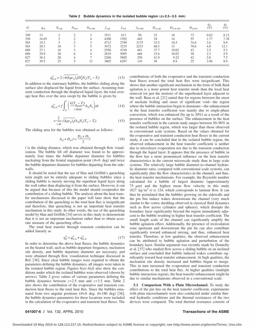
qtr� = qtr,st� + qtr,sl� �17�n order to determine the above heat fluxes, the bubble dynamicsn the heated wall, such as bubble departure frequency, nucleationite density, and bubble departure diameter are necessary, andere obtained through flow visualization technique discussed inef. �36�. Since clear bubble images were required to obtain thearameters defining the bubble dynamics, all images were taken inhe isolated bubble region. Figures 6�a�–6�d� also show the con-itions under which the isolated bubbles were observed �shown byrrows�. Table 2 gives values of various parameters defining theubble dynamics between z=2.5 mm and z=3.5 mm. Table 2lso shows the contribution of the evaporative and transient con-uction heat fluxes to the total heat flux. Since the bubbles ema-ated from two angular positions �=0 deg, =180 deg� �36�,he bubble dynamics parameters for these locations were included
Table 2 Bubble dynamics in the is
G qch Nwall N=0 N=180 fwall f=
50 13 2 2 3 3511 41350 16.05 5 2 4 4300 15965 19.2 5 2 3 4712 27965 20.3 10 3 5 3472 32389 27.1 16 3 4 2550 47489 29.9 20 6 4 2819 50927 36.2 20 4 7 2260 58827 39.5 25 5 12 3805 629
n the calculation of the evaporative and transient heat fluxes. The
41007-6 / Vol. 132, APRIL 2010
ded 19 May 2010 to 128.113.217.15. Redistribution subject to ASM
contributions of both the evaporative and the transient conductionheat fluxes toward the total heat flux were insignificant. Thisshows that another significant mechanism in the form of bulk fluidagitation is a more potent heat transfer mode than the local heatremoval �or just the motion� of the superheated layer adjacent tothe wall. Basu et al. �21� stated that for regions between the onsetof nucleate boiling and onset of significant void—the regionwhere the bubble interaction begin to dominate—the enhancementin the heat transfer coefficient was mainly due to single-phaseconvection, which was enhanced �by up to 30%� as a result of thepresence of bubbles on the surface. The enhancement in the heattransfer coefficient in the current study ranges between 50–90% inthe isolated bubble region, which was larger than those observedin conventional scale systems. Based on the values obtained forthe evaporative and transient conduction heat fluxes in the currentstudy, it can be concluded that in the isolated bubble region, theobserved enhancement in the heat transfer coefficient is neitherdue to microlayer evaporation nor due to the transient conductionthrough the liquid layer. It appears that the presence of bubble inthe flow has a more pronounced influence on the heat transfercharacteristics in the current microscale study than in large scalesystems. The relatively large bubble diameter-to-channel hydrau-lic diameter ratio, compared with conventional scale systems, cansignificantly alter the flow characteristics in the channel, and thus,the heat transfer mechanisms. For example, the Reynolds numbercalculated for a bubble of largest diameter �approximately75 �m� and the highest mean flow velocity in this study�827 kg /m2 s� is 124, which corresponds to laminar flow. It canthus be postulated that the bubbles growing on the sidewalls andthe pin fins induce wakes downstream the channel �very muchsimilar to the vortex shedding observed in classical fluid dynamicssuch as flow across cylinders and spheres�, which disrupts theboundary layer significantly beyond the region immediately adja-cent to the bubble resulting in higher heat transfer coefficient. Thesmall length scale of the channel can significantly amplify thebubble agitation effect. Additionally, the presence of recirculationzone upstream and downstream the pin fin can also contributesignificantly toward enhanced mixing, and thus, enhanced heattransfer. Therefore, at low qualities, the observed enhancementcan be attributed to bubble agitation and perturbation of theboundary layer. Similar argument was recently made by Donnellyet al. �37� who studied flow across a sliding bubble on an inclinedsurface and concluded that bubble induced wakes contribute sig-nificantly toward heat transfer enhancement. At high qualities, thenucleation site density increased and bubbles began to merge.This in turn increased the evaporation and transient conductioncontributions to the total heat flux. At higher qualities �multiplebubble interaction region�, the heat transfer enhancement might bedue to similar mechanisms observed in a conventional scale.
5.1 Comparison With a Plain Microchannel. To study theeffect of the pin fins on the heat transfer coefficient, experimentswith plain microchannels were also conducted under similar ther-mal hydraulic conditions and the thermal resistances of the two
ted bubble region „z=2.5–3.5 mm…
f=180 Dd,wall Dd,=180 Dd,=0
qev�%�
qtr�%�
50 32 18 72 0.62 8.12445 34 14 55 1.77 7.38
2175 32.5 18.5 74.6 2.6 8.92233 40.3 13 70.6 4.8 12.1481 37.7 10.02 43 2.5 5.2468 33.6 10.02 30 2.3 5.9250 41.9 9.22 42 2.8 7.5110 38 8.9 25 3.96 8.9
ola
0
2959557
devices were compared. The total thermal resistance consists of
Transactions of the ASME
E license or copyright; see http://www.asme.org/terms/Terms_Use.cfm

ctrs
Fm
J
Downloa
onductive resistance �Rcond� resulting from heat conduction fromhe base of the silicon block to the channel surface; sensible heatesistance due to heating of the liquid �Rheat�; and convective re-istance �Rconv� resulting from convection from the channel walls
ig. 8 Comparison of convective resistance as a function ofass flow rate for both devices
Fig. 10 Comparison of heat transfer coefficients for a mic2 2
mass fluxes: „a… Gch=282 kg/m s, „b… Gch=345 kg/m s, and „ournal of Heat Transfer
ded 19 May 2010 to 128.113.217.15. Redistribution subject to ASM
to the fluid. Since the experiments were conducted at similar massflow rates for both devices, the resistances due to sensible heatingwere the same. Likewise, the conductive resistance was the samefor the two devices. Thus, only the convective resistance was
Fig. 9 Enhancement in the single-phase Nusselt number fordifferent Reynolds numbers
hannel with pin fins and a plain microchannel for different2
roc
c… Gch=413 kg/m sAPRIL 2010, Vol. 132 / 041007-7
E license or copyright; see http://www.asme.org/terms/Terms_Use.cfm
evbwmtfiNbbtRtooetnehctetbm
0
Downloa
valuated and compared. Figure 8 compares the single-phase con-ective resistance �Eq. �7�� as a function of mass flow rate foroth microchannel systems. The convective resistance decreasesith increasing mass flow rate for both devices. The lower ther-al resistance of the microchannels with pin fins compared with
he plain microchannel is a result of the higher heat transfer coef-cient and larger surface area. Figure 9 compares the ratio of theusselt number—based on the channel hydraulic diameter—foroth devices as a function of Reynolds number �ReD definedased on hydraulic diameter of the channel�. The enhancement ofhe heat transfer coefficient increased from 1.3 to 3 when theeynolds number increased from 84 to 197. Therefore, in addition
o the surface area enhancement �Apin=1.25 Aplain�, the presencef pin fins significantly affects the hydrodynamic characteristicsf the flow resulting in increased heat transfer coefficient. Thenhancement increase with the Reynolds number can be attributedo the wake interaction between the pin fins. At low Reynoldsumber, the wake interaction is less rigorous, and thus, a lowernhancement in the heat transfer coefficient was observed. But atigher Reynolds number, the interaction between the wakes in-reased, promoting advection �mixing�, and thus, reducing thehermal resistance. Figures 10�a�–10�c� show the heat transfer co-fficient as a function of mass quality for both devices. The heatransfer coefficient followed similar trend with respect to quality,ut was quantitatively lower for the plain microchannel for all
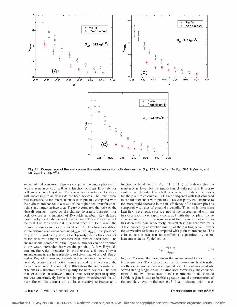
Fig. 11 Comparison of thermal convective resistances for„c… Gch=413 kg/m2 s
ass fluxes. The comparison of the convective resistance as a
41007-8 / Vol. 132, APRIL 2010
ded 19 May 2010 to 128.113.217.15. Redistribution subject to ASM
function of local quality �Figs. 11�a�–11�c�� also shows that theresistance is lower for the microchannel with pin fins. It is alsoevident that the rate at which the convective resistance decreasesfor the plain microchannel is higher compared with that observedin the microchannel with pin fins. This can partly be attributed tothe more rapid decrease in the fin efficiency of the micro pin finscompared with that of channel sidewalls. Thus, with increasingheat flux, the effective surface area of the microchannel with pinfins decreased more rapidly compared with that of plain micro-channel. As a result, the resistance of the microchannel with pinfins decreases more moderately. Nevertheless, the heat transfer isstill enhanced by convective mixing of the pin fins, which lowersthe convective resistances compared with plain microchannel. Theenhancement in heat transfer coefficient is quantified by an en-hancement factor Ep defined as
Ep =hpin fin
hplain�18�
Figure 12 shows the variation in the enhancement factor for dif-ferent qualities. The enhancement in the two-phase heat transfercoefficient is smaller when compared with the enhancement ob-served during single-phase. As discussed previously, the enhance-ment in the two-phase heat transfer coefficient in the isolatedbubble region is due to bubble agitation and the perturbation of
h devices: „a… Gch=282 kg/m2 s, „b… Gch=345 kg/m2 s, and
botthe boundary layer by the bubbles. Unlike in channel with micro-
Transactions of the ASME
E license or copyright; see http://www.asme.org/terms/Terms_Use.cfm

partcctiea=
6
pmfi
A
u�
Fc
J
Downloa
in fins, where the presence of pin fins shadows the agitationffect, in plain microchannel, such agitation can affect extendedegions of the channel. As a result, the heat transfer coefficient forhe plain channel increases at a higher rate compared with micro-hannel with pin fins in the isolated bubble region. But with in-reasing heat flux, for the microchannel with pin fins in the mul-iple bubble interaction region, the heat transfer coefficientncreases significantly due to convective mixing aided by the pres-nce of the pin fins. It follows that the enhancement increasesfter reaching a minimum, which was observed for both Gch282 kg /m2 s and Gch=417 kg /m2 s.
SummarySubcooled and low quality saturated flow boiling across micro
in fins entrenched in a microchannel was studied for variousass fluxes and heat fluxes. The following summarizes the mainndings of this study.
• Flow visualization revealed the existence of isolatedbubbles, bubbles interacting, multiple flow pattern, and an-nular regions along the channel length. The observed flowpatterns were mapped as a function of the boiling numberalong the channel length.
• Single-phase heat transfer coefficient for the microchannelswith pin fins was found to be considerably higher comparedwith the plain wall channels. This was attributed to a com-bination of enhanced area and mixing.
• Considerable enhancement in the heat transfer coefficientduring subcooled boiling over the corresponding single-phase heat transfer coefficient was observed. In the isolatedbubbles region, this enhancement was attributed to the agi-tation of the liquid due to bubble protrusion and disruptionof the boundary layer.
• The heat transfer coefficient during subcooled boiling forthe microchannel with pin fins was higher than the corre-sponding value for plain microchannel. But the enhance-ment in the heat transfer coefficient was smaller in compari-son to that observed during single-phase flow, especially inthe isolated bubble region. This was attributed to the reduc-tion in fin efficiency.
cknowledgmentThis work is supported by the Office of Naval Research �ONR�
nder the Multidisciplinary University Research Initiative
ig. 12 Enhancement in the heat transfer coefficient for a mi-rochannel with pin fins as a function of mass quality
MURI� Award No. GG10919 entitled “System-Level Approach
ournal of Heat Transfer
ded 19 May 2010 to 128.113.217.15. Redistribution subject to ASM
for Multi-Phase, Nanotechnology-Enhanced Cooling of HighPower Microelectronic Systems.” The microfabrication was per-formed in part at the Cornell NanoScale Facility �a member of theNational Nanotechnology Infrastructure Network�, which is sup-ported by the National Science Foundation under Grant No. ECS-0335765, its users, Cornell University, and industrial affiliates.
NomenclatureAp platform area �m2�At total surface area �m2�
Asl sliding area swept by bubbles �m2�Bo boiling number �qch� /Ghfg�cp specific heat capacity �kJ /kg K�D diameter of pin fin �m�
Dh hydraulic channel diameter �m�Dd bubble departure diameter �m�Dl bubble lift off departure diameter �m�Ep enhancement factor
f bubble departure frequency �Hz�G mass flux �kg /m2 s�
hfg latent heat of vaporization �kJ/kg�hx local heat transfer coefficient �W /m2 K�H height of microchannel �m�I current �A�
ks substrate thermal conductivity �W /m K�L length of the channel �m�m mass flow rate �kg/s�
Na nucleation site densityNf number of finsNp number of pin fins
Nux local Nusselt number based on characteristiclength scale �hD /kf ;hDh /kf�
P power �W�qev� evaporative heat flux �W /m2�
qev,st� stationary bubble evaporative heat flux�W /m2�
qev,sl� sliding bubble evaporative heat flux �W /m2�qtr,st� stationary bubble quenching heat flux �W /m2�qtr,sl� sliding bubble quenching heat flux �W /m2�Qloss heat loss �W�ReD Reynolds number based on channel hydraulic
diameter �GDh /��Rconv thermal convective resistance �K/W�Rcond thermal conductive resistance �K/W�Rheat resistance due to sensible heating of fluid
�K/W�Tl liquid temperature �K�
Tmx local fluid temperature �K�Tmi inlet fluid temperature �K�Tsat saturation temperature �K�Tx,s local surface temperature �K�
Tthermistor temperature of thermistor �K�ts substrate thickness �m�V voltage �V�W width of rectangular pin fin �m�x vapor quality
Symbol� f fin efficiency�p pin fin efficiency�v vapor density radial angle
References�1� Qu, W., and Siu-Ho, A., 2008, “Liquid Single-Phase in an Array of Micro-Pin-
Fin—Part I: Heat Transfer Characteristics,” ASME J. Heat Transfer, 130�12�,
APRIL 2010, Vol. 132 / 041007-9
E license or copyright; see http://www.asme.org/terms/Terms_Use.cfm

0
Downloa
p. 122402.�2� Qu, W., and Siu-Ho, A., 2008, “Liquid Single-Phase in an Array of Micro-Pin-
Fin—Part II: Pressure Drop Characteristics,” ASME J. Heat Transfer,130�12�, p. 124501.
�3� Krishnamurthy, S., and Peles, Y., 2008, “Flow Boiling of Water in a CircularStaggered Micro-Pin Fin Heat Sink,” Int. J. Heat Mass Transfer, 51�5–6�, pp.1349–1364.
�4� Siu-Ho, A., Qu, W., and Pfefferkorn, F., 2007, “Experimental Study of Pres-sure Drop and Heat Transfer in a Single-Phase Micropin-Fin Heat Sink,”ASME J. Electron. Packag., 129�4�, pp. 479–487.
�5� Cognata, T. J., Hollingsworth, K. D., and Witte, L. C., 2007, “High-SpeedVisualization of Two-Phase Flow in a Micro-Scale Pin-Fin Heat Exchanger,”Heat Transfer Eng., 28�10�, pp. 861–869.
�6� Prasher, R. S., Dirner, J., Chang, J.-Y., Myers, A., Chau, D., He, D., and Prstic,S., 2007, “Nusselt Number and Friction Factor of Staggered Arrays of LowAspect Ratio Micropin-Fins Under Cross Flow for Water as Fluid,” ASME J.Heat Transfer, 129�2�, pp. 141–153.
�7� Kosar, A., and Peles, Y., 2006, “Convective Flow of Refrigerant �R-123�Across a Bank of Micro Pin Fins,” Int. J. Heat Mass Transfer, 49, pp. 3142–3155.
�8� Krishnamurthy, S., and Peles, Y., 2007, “Gas-Liquid Two-Phase Flow Across aBank of Micro Pillars,” Phys. Fluids, 19�4�, p. 043302.
�9� Kosar, A., and Peles, Y., 2007, “Boiling Heat Transfer in a Hydrofoil-BasedMicro Pin Fin Heat Sink,” Int. J. Heat Mass Transfer, 50�5–6�, pp. 1018–1034.
�10� Kosar, A., and Peles, Y., 2007, “Micro Scale Pin Fin Heat Sinks ParametricPerformance Evaluation Study,” IEEE Trans. Compon. Packag. Technol.,30�4�, pp. 855–865.
�11� Siu-Ho, A. M., Qu, W., and Pfefferkorn, F. E., 2006, “Pressure Drop and HeatTransfer in a Single-Phase Micro-Pin-Fin Heat Sink,” ASME Paper No. IM-ECE2006 14777.
�12� Krishnamurthy, S., and Peles, Y., 2008, “Two-Phase Flow Pattern TransitionAcross Micropillars Size Scale Effect at the Micro Scale,” Phys. Fluids, 2, p.023602.
�13� Bjorg, R. W., Hall, G. R., and Rohsenow, W. M., 1982, “Correlation of ForcedConvection Boiling Heat Transfer Data,” Int. J. Heat Mass Transfer, 25, pp.753–757.
�14� Bowring, R. W., 1962, “Physical Model Based on Bubble Detachment andCalculation of Steam Voidage in the Subcooled Region of a Heated Channel,”Institutt for Atomenergi, Halden, Norway, Paper No. Hpr-10.
�15� Bergles, A. E., and Rohsenow, W. M., 1964, “The Determination of ForcedConvection, Surface Boiling Heat Transfer,” ASME J. Heat Transfer, 86, pp.365–372.
�16� Kutateladze, S. S., 1961, “Boiling Heat Transfer,” Int. J. Heat Mass Transfer,4, pp. 31–45.
�17� Kandlikar, S. G., 1998, “Heat Transfer and Flow Characteristics in PartialBoiling, Fully Developed Boiling, and Significant Void Flow Regions of Sub-cooled Flow Boiling,” ASME J. Heat Transfer, 120, pp. 395–401.
�18� Rouhani, S. Z., and Axelsson, E., 1970, “Calculation of Void Volume Fractionin the Subcooled and Quality Boiling Regions,” Int. J. Heat Mass Transfer, 13,pp. 383–393.
�19� Lahey, R. T., 1978, “A Mechanistic Subcooled Boiling Model,” Proceedings of
41007-10 / Vol. 132, APRIL 2010
ded 19 May 2010 to 128.113.217.15. Redistribution subject to ASM
the Sixth International Heat Transfer Conference, Vol. 1, Toronto, Canada, pp.292–297.
�20� Del Valle, V. H. M., and Kenning, D. B. R., 1985, “Subcooled Flow Boiling atHigh Heat Flux,” Int. J. Heat Mass Transfer, 28, pp. 1907–1920.
�21� Basu, N., Warrier, G. R., and Dhir, V. K., 2005, “Wall Heat Flux PartitioningDuring Subcooled Flow Boiling—Part I: Model Development,” ASME J. HeatTransfer, 127, pp. 131–140.
�22� Basu, N., Warrier, G. R., and Dhir, V. K., 2005, “Wall Heat Flux PartitioningDuring Subcooled Flow Boiling—Part II: Model Validation,” ASME J. HeatTransfer, 127, pp. 141–148.
�23� Warrier, G. R., and Dhir, V. K., 2006, “Heat Transfer and Wall Heat FluxPartitioning During Subcooled Flow Nucleate Boiling, A Review,” ASME J.Heat Transfer, 128, pp. 1243–1256.
�24� Huang, L.-D., and Witte, L., 2001, “Highly Subcooled Boiling in Crossflow,”ASME J. Heat Transfer, 123, pp. 1080–1085.
�25� Huang, H. L., and Witte, L. C., 1996, “An Experimental Investigation of theEffects of Subcooling and Velocity on Boiling of Freon-113,” ASME J. HeatTransfer, 118, pp. 436–441.
�26� Chen, J. C., 1966, “Correlation for Boiling Heat Transfer to Saturated Fluids inConvective Flow,” I&EC Process Des. Dev., 5�3�, pp. 322–329.
�27� Shah, M. M., 2005, “Improved General Correlation for Subcooled BoilingHeat Transfer During Flow Across Tubes and Tube Bundles,” HVAC&R Res.,11�2�, pp. 285–303.
�28� Cornwell, K., 1990, “The Influence of Bubbly Flow on Boiling From a Tube ina Bundle,” Int. J. Heat Mass Transfer, 33�12�, pp. 2579–2584.
�29� Gupta, A., 2005, “Enhancement of Boiling Heat Transfer in a 5�3 TubeBundle,” Int. J. Heat Mass Transfer, 48, pp. 3763–3772.
�30� Lee, P. C., Tseng, F. G., and Pan, C., 2004, “Bubble Dynamics in MicroChannels. Part I: Single Microchannel,” Int. J. Heat Mass Transfer, 47, pp.5575–5589.
�31� Kuo, C.-J., Kosar, A., Peles, Y., Virost, S., Mishra, C., and Jensen, M., 2006,“Bubble Dynamics During Boiling in Enhanced Surface Microchannels,” J.Microelectromech. Syst., 15�6�, pp. 1514–1527.
�32� Lie, Y., and Lin, T., 2006, “Subcooled Flow Boiling Heat Transfer and Asso-ciated Bubble Characteristics of R-134a in a Narrow Annular Duct,” Int. J.Heat Mass Transfer, 49, pp. 2077–2089.
�33� Martín-Callizo, C., Palm, B., and Owhaib, W., 2007, “Subcooled Flow Boilingof R-134a in Vertical Channels of Small Diameter,” Int. J. Multiphase Flow,33, pp. 822–832.
�34� Han, C., and Griffith, P., 1965, “The Mechanism of Heat Transfer in NucleatePool Boiling, Bubble Initiation, Growth and Departure,” Int. J. Heat MassTransfer, 8, p. 887904.
�35� Mikic, B. B., and Rohsenow, W. M., 1969, “A New Correlation of Pool-Boiling Data Including the Effect of Heating Surface Characteristics,” ASMEJ. Heat Transfer, 44�14�, pp. 245–250.
�36� Krishnamurthy, S., and Peles, Y., 2010, “Flow Boiling on Micropin Fins En-trenched Inside a Microchannel—Flow Patterns and Bubble Departure Diam-eter and Bubble Frequency,” ASME J. Heat Transfer, 132�4�, p. 041002.
�37� Donnelly, B., O’Donovan, T. S., and Murray, D. B., 2009, “Surface HeatTransfer Due to Sliding Bubble Motion,” Appl. Therm. Eng., 29�7�, pp. 1319–1326.
Transactions of the ASME
E license or copyright; see http://www.asme.org/terms/Terms_Use.cfm