flow rate indicator / totalizer with analog and … · the f110 is the most popular model in our...
TRANSCRIPT
Advantages• Robust IP67 (NEMA Type4X) field enclosure.
It is so rugged, you can even stand on it!• Intrinsically Safe available - ATEX and IECEx
approval for gas and dust applications.• Programming can be done by your own crew, with
the sensible menu-driven structure, saving costand irritation. Know one, know them all!
• Very diverse mounting possibilities: walls, pipes,panels or directly onto outdoor sensors!
Features• Displays instantaneous flow rate, total and
accumulated total.• Large 17mm (0.67") digit selection for flow rate or
total.• Selectable on-screen engineering units; volumetric
or mass.• Auto backup of settings and running totals.• Explosion/flame proof available.• Full Modbus communication RS232/485/TTL.• Loop or battery powered, 8 - 24V AC/DC or
115 - 230V AC power supply.• Sensor supply 3 / 8.2 / 12 / 24V DC.
Signal output• (0)4 - 20mA / 0 - 10V DC according to flow rate.• Scaled pulse output according to accumulated
total.
Signal inputFlow• Ability to process all types of flowmeter signals:
Reed-switch, NAMUR, NPN/PNP pulse, Sine wave(coil), Active pulse signals, (0)4 - 20mA.
Applications• The F-Series is your first and safest choice for field
mount indicators in safe and hazardous area applications. Especially in harsh weatherconditions like rain, snow, salty atmospheres andtemperatures between -40°C up to +80°C (-40°F up to 176°F).
• Liquid flow measurement where re-transmissionof the flow rate and/or totalizer functions orserial communication is required. Alternativebasic models: F010 - F011 - F012 - F014 or moreadvanced F112 - F113 - F118 or the D-Series DINpanel mount flow rate indicators.
DA
TAS
HE
ET
F11
0 -
FLO
W R
ATE
IN
DIC
ATO
R /
TO
TALI
ZE
R
1
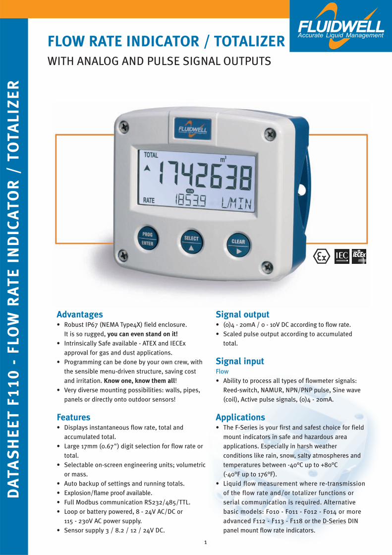
FLOW RATE INDICATOR / TOTALIZERWITH ANALOG AND PULSE SIGNAL OUTPUTS
General informationIntroductionThe F110 is the most popular model in our range of
flow rate / totalizers, complete with pulse and
analog output signals. Even demanding
applications are catered for with our base unit
configuration. A wide selection of options further
enhances the capabilities of this model, including
Intrinsic Safety and full Modbus communication.
DisplayThe display has large 17mm (0.67”) and 8mm
(0.31”) digits which can be set to show flow rate
and totals. On-screen engineering units are easily
configured from a comprehensive menu. The
accumulated total can register up to 11 digits and
is backed-up in EEPROM memory every minute.
For those applications where readability during
day and night is an issue, a white backlight is
available.
ConfigurationAll configuration settings are accessed via a
simple operator menu which can be password
protected. Each setting is clearly indicated with an
alphanumerical description, which avoids
confusing abbreviations and baffling codes. Once
familiar with one F-series product, you will be able
to program all models in the series without a
manual. All settings are safely stored in EEPROM
memory in the event of sudden power failure.
Analog output signalThe flow rate is re-transmitted with the (0)4-20mA
or 0 - 10V DC output signal. The output signal is
updated eight times per second with a filter functi-
on being available to smoothen out the signal if
desired.
The output value is user defined in relation to the
flow rate, e.g. 4mA equals to 15L/Hr and 20mA
equals to 2000L/Hr. The output signal can be
passive, active or isolated where the passive
output type will loop power the F110 as well.
Pulse outputThe scaleable pulse output, reflects the count on
the accumulated display. The pulse length is user
defined from 0.001 second up to 9.999 seconds.
The maximum output frequency is 500Hz.
The output signal can be passive NPN, active PNP
or an isolated electro-mechanical relay.
Signal inputThe F110 accepts most pulse and analog input
signals for volumetric flow or mass flow
measurement. The input signal type can be
selected by the user in the configuration menu
without having to adjust any sensitive mechanical
dip-switches or jumpers. The analog input is
available with lineair and square root calculation
and even as 4 - 20mA input loop powered.
CommunicationAll process data and settings can be read and
modified manually or through the Modbus
communication link (RS232 / RS485).
Full Modbus functionality remains available for the
Intrinsically Safe version (TTL).
Hazardous areasThis model has been ATEX and IECEx certified
Intrinsically Safe for gas and dust applications,
with an allowed ambient temperature of
-40°C to +70°C (-40°F to +158°F). A flame proof Ex d enclosure with ATEX certification is alsoavailable.
EnclosuresVarious types of enclosures can be selected, all
ATEX and IECEx approved. As standard the F110 is
supplied in an GRP panel mount enclosure, which
can be converted to an IP67 / NEMA Type4X GRP
field mount enclosure by the addition of a back
case. Most popular is our rugged aluminum field
mount enclosure with IP67 / NEMA Type4X rating.
Both European or U.S. cable gland entry threads
are available.
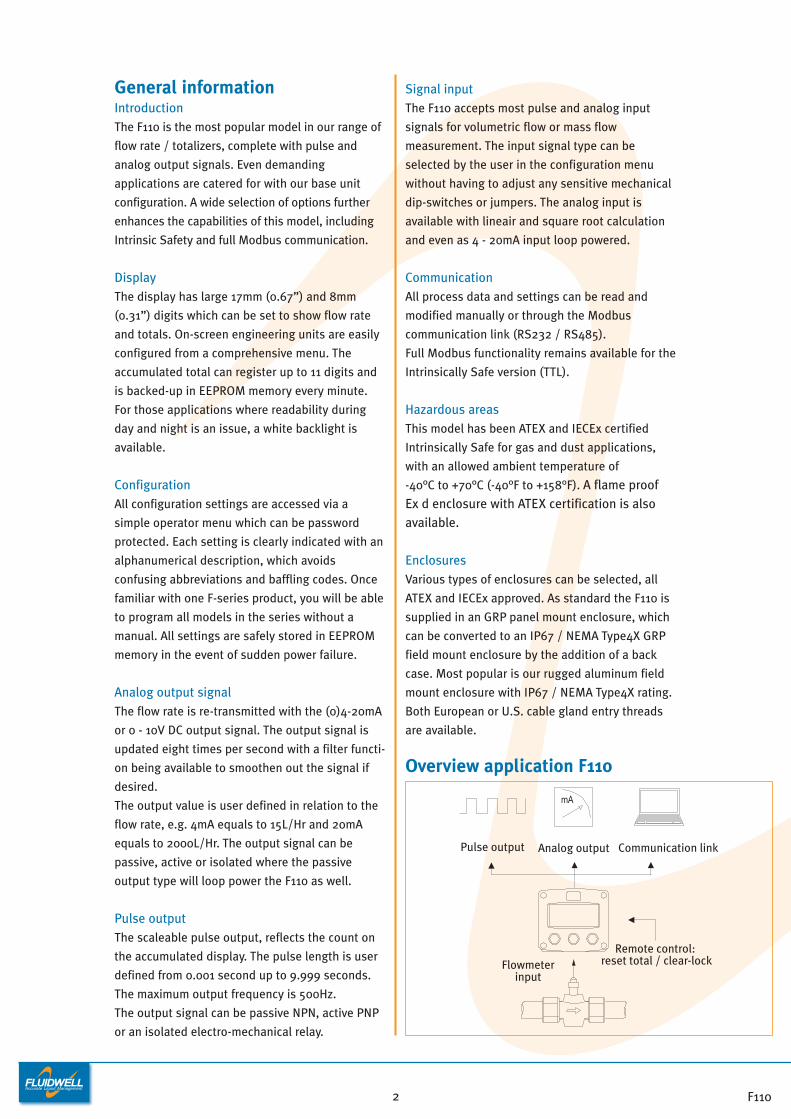
Overview application F110
Pulse output Analog output Communication link
Remote control: reset total / clear-lockFlowmeter
input
F1102
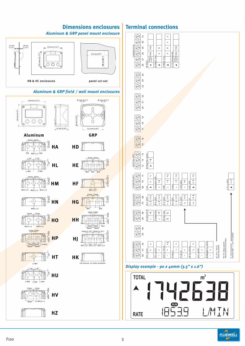
Dimensions enclosuresAluminum & GRP panel mount enclosure
Aluminum & GRP field / wall mount enclosures
Terminal connections
Display example - 90 x 40mm (3.5” x 1.6”)
CB:
RS2
32
CH
: RS4
85 -
2 w
ire
AB
YZ
RX
DTX
D
CT:
TTL
Intri
nsic
ally
Saf
e
P: re
ed s
witc
h / N
PN
P: c
oil
P: n
amur
P: P
NP
A: (0
)4 -
20m
A
P: a
ctiv
e si
gnal
-
+
==
0506
PULS
E O
UTP
UT
0102
POW
ER R
EQU
IREM
ENT
00 -+
PD: 8
- 24
V AC
PD: 8
- 24
V D
C
-+
PF: 2
4V A
C
PM: 1
15 -
230V
AC
PF: 2
4V D
C
PD-X
I: 16
- 30
V D
C
+-
+
OT:
pas
sive
tran
s.O
T:pa
ssiv
etra
ns.
OA:
act
ive
24V
DC
OA:
activ
e24
VD
C
OR
: mec
h. re
lay
OR
:mec
h.re
lay
++
====
0304
PULS
E O
UTP
UT
1011
FLO
WM
ETER
INPU
T
09
+
+ -+
+
+
AP: 4
- 20
mA
AA: 4
- 20
mA
AF: 4
- 20
mA
AU: 0
- 10
V
AI: 4
- 20
mA
AB: 0
- 20
mA
0708
ANAL
OG
OU
TPU
T
+II-
+I +U
I U
+II
+II-
+II
OT:
pas
sive
tran
s.
OA:
act
ive
24V
DC
OR
: mec
h. re
lay
+
++
+I
A - P
L: 4
- 20
mA
+I
IB: R
eset
tota
l + k
eylo
ck
1314
ADD
ITIO
NAL
INPU
T
1218
1917
1516
2728
CO
MM
UN
ICAT
ION
2623
2425
2122
2029
3031
DTR
+12V
CI:
RS4
85 -
4 w
ire
AB
RX
DTX
DD
TR+1
2V
+
-+
PX: 8
- 30
V D
C
-+
ZB: B
ackl
ight
: 12
- 30V
DC
AP -
PX: 8
- 30
V D
CO
utpu
t loo
p po
wer
ed
PB /
PC: b
atte
ry p
ower
edIn
tern
al lo
ng li
fe L
ithiu
m b
atte
ry
PL: i
nput
loop
pow
ered
(term
inal
s G
ND
- 1
- 2 a
re n
ot a
vaila
ble)
F110 3
130 mm (5.12")
120
mm
(4.7
2")
31 mm(1.22")
29 mm(1.14")
115 (4.53")
98
(3.8
6")
panel cut-outHB & HC enclosures
75 mm (2.95")
130 mm (5.12")
112 mm (4.40")
60 m
m (2
.36"
)
120
mm
(4.7
2")
M20 x 1,5PG9 PG9
30mm 30mm
22,5
0mm
M20 x 1,5M16 x 1,5 M16 x 1,5
30mm 30mm
22,5
0mm
M20 x 1,5
22,5
0mm
M20 x 1,5 M20 x 1,5
25mm 25mm
22,5
0mm
1/2"NPT
0.9"
1/2"NPT1/2"NPT 1/2"NPT
1.18" 1.18"
0.9"
HA
HM
HN
HO
HD
HP
HE
HT
HF
HU
HG
HV
HH
6 x M12
12mm 12mm
24mm24mm36mm36mm
14m
m17
mm
Ø12
12mm 12mm
24mm24mm36mm36mm
14m
m17
mm
HK
22,5
0mm
30mm 30mm
Ø16 Ø16Ø20
HJ
22,5
0mm
(0.9
")30mm (1.18") 30mm (1.18")
Ø22 ( 7/8") Ø22 ( 7/8")Ø22 ( 7/8")
22,5
0mm
(0.9
")
Ø22 ( 7/8")
22,5
0mm
25mm 25mm
Ø20 Ø20
Aluminum GRP
Flat bottom, no holes available.
4 x M20 x 1.5
15mm 15mm
HZ
16m
m15
mm
38mm
1/2"NPT 1/2"NPT
1.18" 1.18"
0.9"
HL
Ø 7mm (0.27") Ø 7mm (0.27")
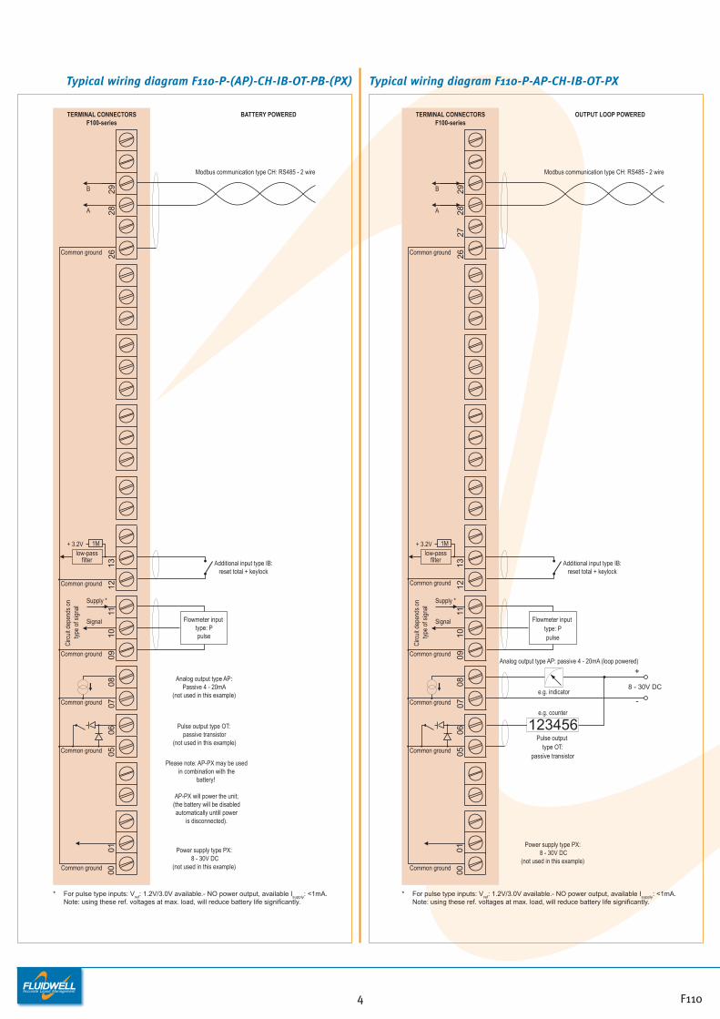
Typical wiring diagram F110-P-(AP)-CH-IB-OT-PB-(PX) Typical wiring diagram F110-P-AP-CH-IB-OT-PX
0910
1112
0605
13
Common ground
Signal
Supply *
Common ground
TERMINAL CONNECTORSF100-series
0708
Common ground
Flowmeter input type: Ppulse
Circ
uit d
epen
ds o
n ty
pe o
f sig
nal
2827
2629
8 - 30V DC
+
-
A
Common ground
B
Common ground
+ 3.2Vlow-pass
filter
1M
* For pulse type inputs: Vref: 1.2V/3.0V available.- NO power output, available Isupply: <1mA. Note: using these ref. voltages at max. load, will reduce battery life significantly.
123456e.g. counter
Additional input type IB:reset total + keylock
e.g. indicator
Analog output type AP: passive 4 - 20mA (loop powered)
Modbus communication type CH: RS485 - 2 wire
Pulse output type OT:
passive transistor
OUTPUT LOOP POWERED
Common ground 0001
Power supply type PX: 8 - 30V DC
(not used in this example)
0910
11
Common ground
Common ground
Signal
Supply *
TERMINAL CONNECTORSF100-series
0708
Common ground
Circ
uit d
epen
ds o
n ty
pe o
f sig
nal
2826
29
A
Common ground
B
* For pulse type inputs: Vref: 1.2V/3.0V available.- NO power output, available Isupply: <1mA. Note: using these ref. voltages at max. load, will reduce battery life significantly.
Flowmeter input type: Ppulse
Modbus communication type CH: RS485 - 2 wire
Analog output type AP:Passive 4 - 20mA
(not used in this example)
BATTERY POWERED
Additional input type IB:reset total + keylock
1213
+ 3.2Vlow-pass
filter
1M
0605Common ground
Please note: AP-PX may be used in combination with the
battery!
AP-PX will power the unit;(the battery will be disabled automatically untill power
is disconnected).
Pulse output type OT: passive transistor
(not used in this example)
Common ground 0001 Power supply type PX:
8 - 30V DC(not used in this example)
F1104
0001
0209
1011
1206
0513
Common ground
Signal
Supply *
Common ground
TERMINAL CONNECTORSF100-series
8 - 24V DC
+
-
0708
Common ground
Common ground
Main supply
2827
2629
Common ground
Common ground
+ 3.2Vlow-pass
filter
1M
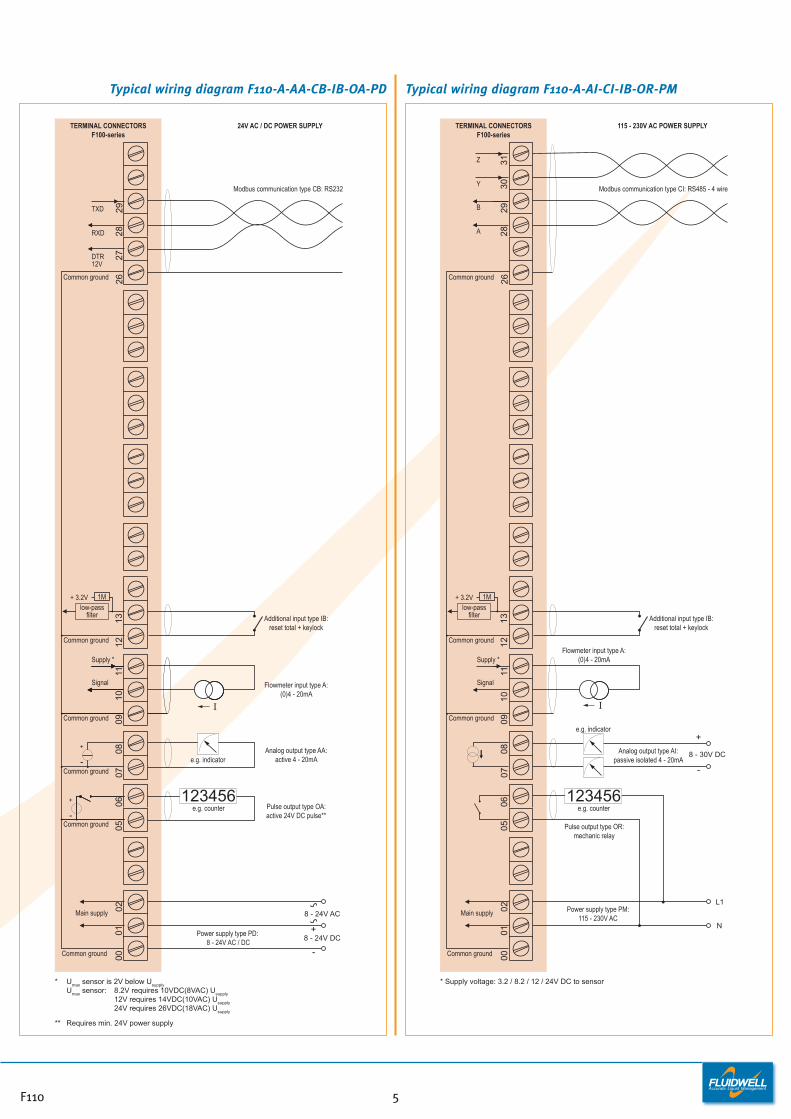
* Umax sensor is 2V below Usupply Umax sensor: 8.2V requires 10VDC(8VAC) Usupply 12V requires 14VDC(10VAC) Usupply 24V requires 26VDC(18VAC) Usupply
** Requires min. 24V power supply
RXD
TXD
DTR12V
8 - 24V AC
Pulse output type OA:active 24V DC pulse**
Analog output type AA:active 4 - 20mA
Flowmeter input type A:(0)4 - 20mA
e.g. indicator
+
-
+
- e.g. counter123456
Additional input type IB:reset total + keylock
Modbus communication type CB: RS232
Power supply type PD: 8 - 24V AC / DC
24V AC / DC POWER SUPPLY
0001
0209
1011
0605
TERMINAL CONNECTORSF100-series
N
0708
Common ground
Main supply
26
8 - 30V DC
+
-
Common ground
Common ground
Signal
Supply *
e.g. counter123456
L1
Flowmeter input type A:(0)4 - 20mA
Pulse output type OR:mechanic relay
e.g. indicator
1213
Common ground
+ 3.2V 1M
Additional input type IB:reset total + keylock
Power supply type PM:115 - 230V AC
Analog output type AI:passive isolated 4 - 20mA
2831
3029
Y
Z
A
B
Modbus communication type CI: RS485 - 4 wire
115 - 230V AC POWER SUPPLY
* Supply voltage: 3.2 / 8.2 / 12 / 24V DC to sensor
low-passfilter
F110 5
Typical wiring diagram F110-A-AA-CB-IB-OA-PD Typical wiring diagram F110-A-AI-CI-IB-OR-PM

Hazardous area applicationsThe F110-XI has been certified according ATEXand IECEx by DEKRA for use in Intrinsically Safeapplications with an ambient temperature of -40°C to +70°C (-40°F to +158°F). • The ATEX markings for gas and dust
applications are:II 1 G Ex ia IIB/IIC T4 GaII 1 D Ex ia IIIC T100 °C Da.
• The IECEx markings for gas and dustapplications are: Ex ia IIC/IIB T4 Ga and Ex ia IIIC T100 °C Da.
Besides the I.S. power supply for the pulseoutput, it is allowed to connect up to three I.S.power supplies in IIB/IIIC applications or one inIIC applications. Consult the certificate for themaximum input and output values of thecircuits. Full functionality of the F110 remainsavailable, including 4 - 20mA output, pulseoutput and Modbus communication (type CT).Power supply type PD-XI offers a 8.2V sensorsupply e.g. for one Namur sensor.An ATEX approved flame proof Ex d enclosure isavailable as well. Please contact your supplierfor further details.
Certificate of conformity KEMA 03ATEX1074 X• IECEx DEK 11.0042X
TERMINAL CONNECTORSF100-series
HAZARDOUS AREA SAFE AREA
0910
11
Common ground
Signal
Supply *
Circ
uit d
epen
ds o
n ty
pe o
f sig
nal
* For pulse type inputs: Vref: 1.2V/3.0V available.- NO power output, available Isupply: <1mA. Note: using these ref. voltages at max. load, will reduce battery life significantly.
Flow meter input type: Ppulse
Common ground 0708
RXD
Common ground
TXD
2826
29
Modbus communication type CT: TTLPossible for battery powered applications
(not used in this example).
Please note: communciation type CT is not allowed in IIC applications.
DTR+12V
27
Additional input type IB:reset total + keylock
Ci is negligiblysmall
1213
Common ground
+ 3.2V
low-passfilter
1M
0506
Common ground
Ci is negligiblysmall
Analog output type AP:passive 4 - 20mA
(not used in this example)
Please note: AP may be used in combination with the
battery!
AP will power the unit (output loop powered);
the battery will be disabled automatically untill power
is disconnected).
Pulse output type OT: passive transistor
(not used in this example)
Configuration example IIB /IIIC and IIC F110-P-(AP)-(CT)-IB-(OT)-PC-XI - Battery powered unit
F1106
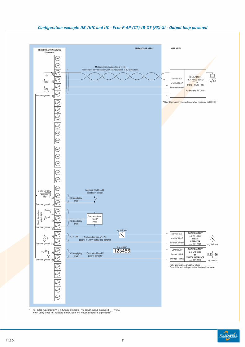
Configuration example IIB /IIIC and IIC - F110-P-AP-(CT)-IB-OT-(PX)-XI - Output loop powered
1011
Common ground
Signal
Supply *
Circ
uit d
epen
ds o
n ty
pe o
f sig
nal
Analog output type AP - PX:passive 4 - 20mA (output loop powered)
Common ground
123456
Ci = 17nF
Flow meter input type: Ppulse
Common ground
e.g. counter
+
-
POWER SUPPLYe.g. MTL 5525
and / or REPEATER
e.g. MTL 5541
Uo=max 30V
Io=max 100mA
Po=max 750mW
+
-
POWER SUPPLYe.g. MTL 5525
or SWITCH INTERFACE
e.g. MTL 5511
Uo=max 30V
Io=max 100mA
Po=max 750mWe.g. counter
123456
e.g. indicator
e.g. indicator
TERMINAL CONNECTORSF100-series
HAZARDOUS AREA SAFE AREA
Additional input type IB:reset total + keylock
Ci is negligiblysmall
1213
Common ground
RXD
Common ground
TXD
2826
29
DTR+12V
27
ISOLATOR:I.S. Certified Isolator
TTL to RS232 / RS422 / TTL
For example: MTL5051
Uo=max 30V
Io=max 250mA
Po=max 850mW
+
-
e.g. PC
+ 3.2V
low-passfilter
1M
Modbus communication type CT: TTLPlease note: communciation type CT is not allowed in IIC applications.
* For pulse type inputs: Vref: 1.2V/3.0V available.- NO power output, available Isupply: <1mA. Note: using these ref. voltages at max. load, will reduce battery life significantly
Pulse output type OT:passive transistor
Ci is negligiblysmall
Ci is negligiblysmall
* Note: Communication only allowed when configured as IIB / IIIC.
0907
0805
06
Note: above values are safety values.Consult the technical specification for operational values.
F110 7

Configuration example IIB / IIIC and IIC - F110-A-AF-(CT)-IB-OT-PD-XI - Power requirement 16 - 30V DC
Common ground
TOTAL Co OF ALL CONNECTEDANALOG APPARATUS IN IICAPPLICATIONS MAY NOT
EXCEED 66nF MINUS 17nF(17nF IS USED BY THE ANALOG
OUTPUT SIGNAL TERMINAL 7 + 8).
Main supply Power supply type PD: 16 - 30V DC (please note: PD and battery supply (type PC) is NOT allowed in IIC applications).
Common ground
123456
Ci = 17nF Analog output type AF:passive floating 4 - 20mA
1011
Common ground
Signal
Supply *
Circ
uit d
epen
ds o
n ty
pe o
f sig
nal
Ci is negligiblysmall
Flow meter input type: A(0)4 - 20mA
e.g. counter
+
-
POWER SUPPLY
For example MTL5525
Uo=max 30V
Io=max 100mA
Po=max 750mW
+
-
POWER SUPPLYe.g. MTL 5525
or SWITCH INTERFACE
e.g. MTL 5511
Uo=max 30V
Io=max 100mA
Po=max 750mWe.g. counter
123456
e.g. indicator
* Note power supply type PD: the supply voltage to pulse sensors is maximum 8.7V (Uo=max 8.7V Io=max 25mA Po=max 150mW) and to analog sensors as connected to terminal 1 (internally linked).
TERMINAL CONNECTORSF100-series
HAZARDOUS AREA SAFE AREA
Additional input type IB:reset total + keylock
Ci is negligiblysmall
1213
Common ground
RXD
Common ground
TXD
2826
29
DTR+12V
27
ISOLATOR:I.S. Certified Isolator
TTL to RS232 / RS422 / TTL
For example: MTL5051
Uo=max 30V
Io=max 250mA
Po=max 850mW
+
-
e.g. PC
+ 3.2V
low-passfilter
1M
Modbus communication type CT: TTLPlease note: communciation type CT is not allowed in IIC applications.
Pulse output type OT:passive transistor
Ci is negligiblysmall
Note: above values are safety values.Consult the technical specification for operational values.
0907
0805
06
00
01
* Note: Communication only allowed when configured as IIB / IIIC.
F1108
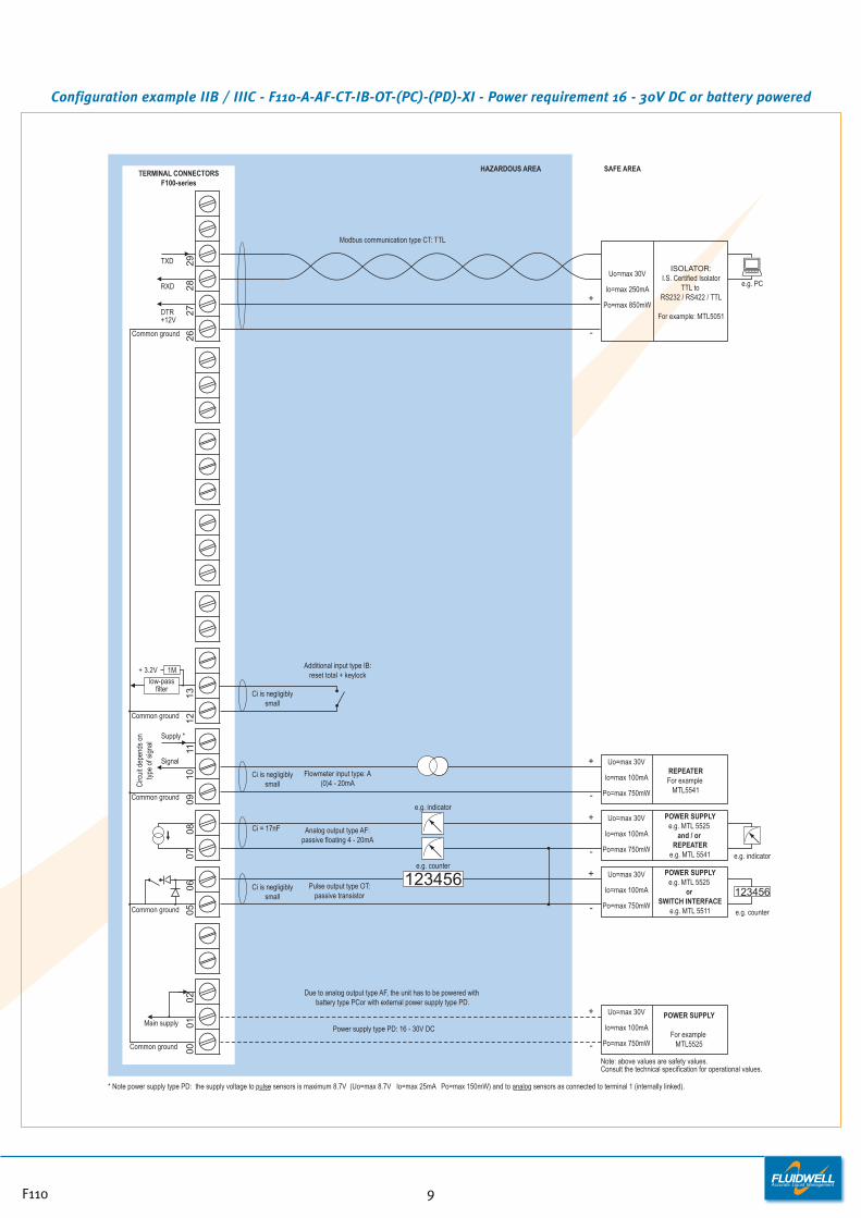
Configuration example IIB / IIIC - F110-A-AF-CT-IB-OT-(PC)-(PD)-XI - Power requirement 16 - 30V DC or battery powered
Ci = 17nF
0910
11
Common ground
Common ground
Signal
Supply *
Main supply
Circ
uit d
epen
ds o
n ty
pe o
f sig
nal
* Note power supply type PD: the supply voltage to pulse sensors is maximum 8.7V (Uo=max 8.7V Io=max 25mA Po=max 150mW) and to analog sensors as connected to terminal 1 (internally linked).
Power supply type PD: 16 - 30V DC
Analog output type AF:passive floating 4 - 20mA
0506
Common ground
0001
0207
08
123456
Flowmeter input type: A(0)4 - 20mA
e.g. counter
+
-
+
-
POWER SUPPLYe.g. MTL 5525
and / or REPEATER
e.g. MTL 5541
Uo=max 30V
Io=max 100mA
Po=max 750mW
Uo=max 30V
Io=max 100mA
Po=max 750mW
+
-
POWER SUPPLY
For example MTL5525
Uo=max 30V
Io=max 100mA
Po=max 750mW
+
-
POWER SUPPLYe.g. MTL 5525
or SWITCH INTERFACE
e.g. MTL 5511
Uo=max 30V
Io=max 100mA
Po=max 750mWe.g. counter
123456
e.g. indicator
e.g. indicator
TERMINAL CONNECTORSF100-series
HAZARDOUS AREA SAFE AREA
Additional input type IB:reset total + keylock
Ci is negligiblysmall
1213
Common ground
RXD
Common ground
TXD
2826
29
DTR+12V
27
ISOLATOR:I.S. Certified Isolator
TTL to RS232 / RS422 / TTL
For example: MTL5051
Uo=max 30V
Io=max 250mA
Po=max 850mW
+
-
e.g. PC
+ 3.2V
low-passfilter
1M
Modbus communication type CT: TTL
Due to analog output type AF, the unit has to be powered with battery type PCor with external power supply type PD.
Pulse output type OT:passive transistor
Ci is negligiblysmall
Ci is negligiblysmall
Note: above values are safety values.Consult the technical specification for operational values.
REPEATERFor example
MTL5541
F110 9
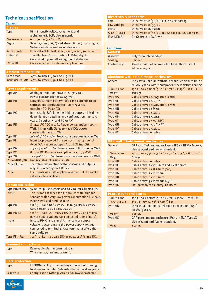
Technical specificationGeneralDisplayType High intensity reflective numeric and
alphanumeric LCD, UV-resistant.Dimensions 90 x 40mm (3.5” x 1.6”).Digits Seven 17mm (0.67") and eleven 8mm (0.31") digits.
Various symbols and measuring units.Refresh rate User definable: fast, 1sec , 3sec, 15sec, 30sec, off.Option ZB Transflective LCD with white LED-backlight.
Good readings in full sunlight and darkness. Note ZB Only available for safe area applications.
Ambient temperatureSafe areas -40°C to +80°C (-40°F to +176°F).Intrinsically Safe -40°C to +70°C (-40°F to +158°F).
Power requirementsType AP Analog output loop powerd, 8 - 30V DC.
Power consumption max 0.5 Watt.Type PB Long life Lithium battery - life-time depends upon
settings and configuration - up to 5 years.(requires PD, PL or PX)
Type PC Intrinsically Safe long life lithium battery - life-time depends upon settings and configuration - up to 5 years. (requires XI and PD or PX)
Type PD 8 - 24V AC / DC ± 10%. Power consumption max. 5 Watt. Intrinsically Safe: 16 - 30V DC; power consumption max. 1 Watt.
Type PF 24V AC / DC ± 10%. Power consumption max. 15 Watt.Type PL Input loop powered from sensor signal 4 - 20mA
(type “A”) - requires types AI and OT (not Xi).Type PM 115 - 230V AC ± 10%. Power consumption max. 15 Watt.Type PX 8 - 30V DC. Power consumption max. 0.75 Watt. Type ZB 12 - 30V DC ± 10%. Power consumption max. 1.5 Watt.
Note PB/PF/PM Not available Intrinsically Safe.Note PF/PM The total consumption of the sensors and outputs
may not exceed 400mA @ 24V.Note For Intrinsically Safe applications, consult the safety
values in the certificate.
Sensor excitationType PB/PC/PX 3V DC for pulse signals and 1.2V DC for coil pick-up.
Note This is not a real sensor supply. Only suitable for sensors with a very low power consumption like coils(sine wave) and reed-switches.
Type PD 1.2 / 3 / 8.2 / 12 / 24V DC - max. 50mA @ 24V DC.Umax sensor is 2V below Usupply
Type PD-XI 1.2 / 3 / 8.2V DC - max. 7mA @ 8.2V DC and mains power supply voltage (as connected to terminal 1).
Note In case PD-XI and signal A: the sensor supply voltage is according to the power supply voltage connected to terminal 1. Also terminal 2 offers the same voltage.
Type PF / PM 1.2 / 3 / 8.2 / 12 / 24V DC - max. 400mA @ 24V DC.
Terminal connectionsType Removable plug-in terminal strip.
Wire max. 1.5mm2 and 2.5mm2.
Data protectionType EEPROM backup of all settings. Backup of running
totals every minute. Data retention at least 10 years.Password Configuration settings can be password protected.
Directives & StandardsEMC Directive 2014/30/EU, FCC 47 CFR part 15.Low voltage Directive 2014/35/EURoHS Directive 2011/65/EUATEX / IECEx Directive 2014/34/EU, IEC 600079-0, IEC 60079-11.IP & NEMA EN 60529 & NEMA 250
EnclosureGeneralWindow Polycarbonate window.Sealing Silicone.Control keys Three industrial micro-switch keys. UV-resistant
silicone keypad.
Aluminum wall / field mount enclosuresGeneral Die-cast aluminum wall/field mount enclosure IP67 /
NEMA Type4X with 2-component UV-resistant coating.Dimensions 130 x 120 x 75mm (5.12" x 4.72" x 2.95") - W x H x D.Weight 1100 gr.
Type HA Cable entry: 2 x PG9 and 1 x M20. Type HL Cable entry: 2 x 1/2" NPT.Type HM Cable entry: 2 x M16 and 1 x M20. Type HN Cable entry: 1 x M20. Type HO Cable entry: 2 x M20. Type HP Cable entry: 6 x M12. Type HT Cable entry: 1 x 1/2" NPT.Type HU Cable entry: 3 x 1/2" NPT.Type HV Cable entry: 4 x M20. Type HZ Cable entry: no holes.
GRP wall / field mount enclosuresGeneral GRP wall/field mount enclosure IP67 / NEMA Type4X,
UV-resistant and flame retardant. Dimensions 130 x 120 x 75mm (5.12" x 4.72" x 2.95") - W x H x D.Weight 600 gr.
Type HD Cable entry: no holes.Type HE Cable entry: 2 x Ø 16mm and 1 x Ø 20mm.Type HF Cable entry: 1 x Ø 22mm (7/8").Type HG Cable entry: 2 x Ø 20mm. Type HH Cable entry: 6 x Ø 12mm. Type HJ Cable entry: 3 x Ø 22mm (7/8"). Type HK Flat bottom, cable entry: no holes.
Panel mount enclosuresDimensions 130 x 120 x 60mm (5.12" x 4.72" x 2.36") - W x H x D.Panel cut-out 115 x 98mm (4.53" x 3.86") L x H.
Type HB Die-cast aluminum panel mount enclosure IP65 / NEMA Type4X.
Weight 600 gr.Type HC GRP panel mount enclosure IP65 / NEMA Type4X,
UV-resistant and flame retardant.Weight 450 gr.
F11010
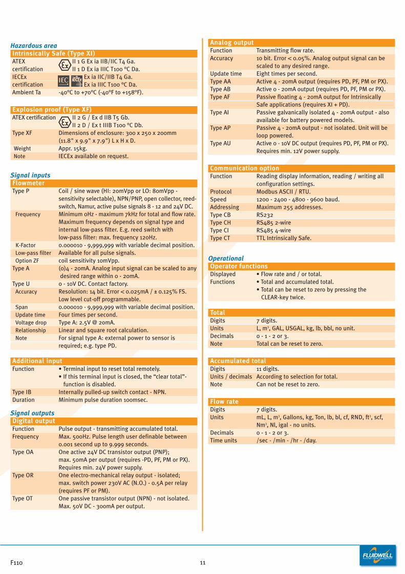
Hazardous areaIntrinsically Safe (Type XI)ATEX II 1 G Ex ia IIB/IIC T4 Ga.certification II 1 D Ex ia IIIC T100 °C Da.IECEx Ex ia IIC/IIB T4 Ga.certification Ex ia IIIC T100 °C Da.Ambient Ta -40°C to +70°C (-40°F to +158°F).
Explosion proof (Type XF)ATEX certification II 2 G / Ex d IIB T5 Gb.
II 2 D / Ex t IIIB T100 °C Db.Type XF Dimensions of enclosure: 300 x 250 x 200mm
(11.8" x 9.9" x 7.9") L x H x D.Weight Appr. 15kg.Note IECEx available on request.
Signal inputsFlowmeterType P Coil / sine wave (HI: 20mVpp or LO: 80mVpp -
sensitivity selectable), NPN/PNP, open collector, reed-switch, Namur, active pulse signals 8 - 12 and 24V DC.
Frequency Minimum 0Hz - maximum 7kHz for total and flow rate. Maximum frequency depends on signal type and internal low-pass filter. E.g. reed switch with low-pass filter: max. frequency 120Hz.
K-Factor 0.000010 - 9,999,999 with variable decimal position.Low-pass filter Available for all pulse signals.Option ZF coil sensitivity 10mVpp.
Type A (0)4 - 20mA. Analog input signal can be scaled to anydesired range within 0 - 20mA.
Type U 0 - 10V DC. Contact factory.Accuracy Resolution: 14 bit. Error < 0.025mA / ± 0.125% FS.
Low level cut-off programmable.Span 0.000010 - 9,999,999 with variable decimal position.Update time Four times per second.Voltage drop Type A: 2.5V @ 2omA.Relationship Linear and square root calculation.Note For signal type A: external power to sensor is
required; e.g. type PD.
Additional inputFunction • Terminal input to reset total remotely.
• If this terminal input is closed, the “clear total”-function is disabled.
Type IB Internally pulled-up switch contact - NPN.Duration Minimum pulse duration 100msec.
Signal outputsDigital outputFunction Pulse output - transmitting accumulated total.Frequency Max. 500Hz. Pulse length user definable between
0.001 second up to 9.999 seconds.Type OA One active 24V DC transistor output (PNP);
max. 50mA per output (requires -PD, PF, PM or PX).Requires min. 24V power supply.
Type OR One electro-mechanical relay output - isolated; max. switch power 230V AC (N.O.) - 0.5A per relay (requires PF or PM).
Type OT One passive transistor output (NPN) - not isolated. Max. 50V DC - 300mA per output.
Analog outputFunction Transmitting flow rate.Accuracy 10 bit. Error < 0.05%. Analog output signal can be
scaled to any desired range.Update time Eight times per second.Type AA Active 4 - 20mA output (requires PD, PF, PM or PX).Type AB Active 0 - 20mA output (requires PD, PF, PM or PX).Type AF Passive floating 4 - 20mA output for Intrinsically
Safe applications (requires XI + PD).Type AI Passive galvanically isolated 4 - 20mA output - also
available for battery powered models.Type AP Passive 4 - 20mA output - not isolated. Unit will be
loop powered. Type AU Active 0 - 10V DC output (requires PD, PF, PM or PX).
Requires min. 12V power supply.
Communication optionFunction Reading display information, reading / writing all
configuration settings.Protocol Modbus ASCII / RTU.Speed 1200 - 2400 - 4800 - 9600 baud.Addressing Maximum 255 addresses.Type CB RS232Type CH RS485 2-wire Type CI RS485 4-wireType CT TTL Intrinsically Safe.
OperationalOperator functionsDisplayed • Flow rate and / or total.Functions • Total and accumulated total.
• Total can be reset to zero by pressing the CLEAR-key twice.
TotalDigits 7 digits.Units L, m3, GAL, USGAL, kg, lb, bbl, no unit.Decimals 0 - 1 - 2 or 3. Note Total can be reset to zero.
Accumulated totalDigits 11 digits.Units / decimals According to selection for total.Note Can not be reset to zero.
Flow rateDigits 7 digits.Units mL, L, m3, Gallons, kg, Ton, lb, bl, cf, RND, ft3, scf,
Nm3, Nl, igal - no units.Decimals 0 - 1 - 2 or 3.Time units /sec - /min - /hr - /day.
F110 11
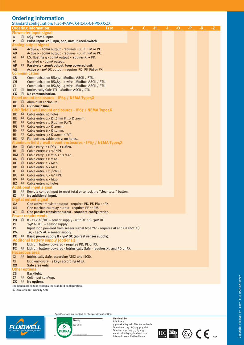
Ordering information Standard configuration: F110-P-AP-CX-HC-IX-OT-PX-XX-ZX.Ordering information: F110 -_ -A _ -C _ -H _ -I _ -O _ -P _ -X _ -Z _Flowmeter input signalA (0)4 - 20mA input.P Pulse input: coil, npn, pnp, namur, reed-switch.Analog output signalAA Active 4 - 20mA output - requires PD, PF, PM or PX.AB Active 0 - 20mA output - requires PD, PF, PM or PX.AF I.S. floating 4 - 20mA output - requires XI + PD.AI Isolated 4 - 20mA output.AP Passive 4 - 20mA output, loop powered unit.AU Active 0 - 10V DC output - requires PD, PF, PM or PX.CommunicationCB Communication RS232 - Modbus ASCII / RTU.CH Communication RS485 - 2-wire - Modbus ASCII / RTU.CI Communication RS485 - 4-wire - Modbus ASCII / RTU.CT Intrinsically Safe TTL - Modbus ASCII / RTU.CX No communication.Panel mount enclosures - IP65 / NEMA Type4XHB Aluminum enclosure.HC GRP enclosure.GRP field / wall mount enclosures - IP67 / NEMA Type4XHD Cable entry: no holes.HE Cable entry: 2 x Ø 16mm & 1 x Ø 20mm.HF Cable entry: 1 x Ø 22mm (7/8”).HG Cable entry: 2 x Ø 20mm.HH Cable entry: 6 x Ø 12mm.HJ Cable entry: 3 x Ø 22mm (7/8”).HK Flat bottom, cable entry: no holes.Aluminum field / wall mount enclosures - IP67 / NEMA Type4XHA Cable entry: 2 x PG9 + 1 x M20.HL Cable entry: 2 x 1/2”NPT.HM Cable entry: 2 x M16 + 1 x M20.HN Cable entry: 1 x M20.HO Cable entry: 2 x M20.HP Cable entry: 6 x M12.HT Cable entry: 1 x 1/2”NPT.HU Cable entry: 3 x 1/2”NPT.HV Cable entry: 4 x M20.HZ Cable entry: no holes.Additional input signalIB Remote control input to reset total or to lock the “clear total” button.IX No additional input.Digital output signalOA One active transistor output - requires PD, PF, PM or PX.OR One mechanical relay output - requires PF or PM.OT One passive transistor output - standard configuration.Power requirementsPD 8 - 24V AC/DC + sensor supply - with XI: 16 - 30V DC.PF 24V AC/DC + sensor supply.PL Input loop powered from sensor signal type “A” - requires AI and OT (not XI).PM 115 - 230V AC + sensor supply.PX Basic power supply 8 - 30V DC (no real sensor supply).Additonal battery supply (optional)PB Lithium battery powered - requires PD, PL or PX.PC Lithium battery powered - Intrinsically Safe - requires XI, and PD or PX.Hazardous areaXI Intrinsically Safe, according ATEX and IECEx.XF Ex d enclosure - 3 keys according ATEX.XX Safe area only.Other optionsZB Backlight. ZF Coil input 10mVpp.ZX No options.
The bold marked text contains the standard configuration.Available Intrinsically Safe.
Copy
righ
t: F
luid
wel
l bv
- 201
7 - F
110-
DAT
A-EN
-V17
27
12
Specifications are subject to change without notice.
Fluidwell bvP.O. Box 65460 AA - Veghel - The NetherlandsTelephone: +31 (0)413 343 786Telefax: +31 (0)413 363 443email: [email protected] Internet: www.fluidwell.com