fluid flow and heat transfer characteristics of jorge l
TRANSCRIPT

Hessam Taherian1
Department of Mechanical Engineering,
University of Alabama at Birmingham,
1720 2nd Avenue S,
Birmingham, AL 35294
e-mail: [email protected]
Jorge L. AlvaradoDepartment of Engineering Technology
and Industrial Distribution,
Texas A&M University,
3367 TAMU,
College Station, TX 77843
Kalpana TumuluriDepartment of Engineering Technology
and Industrial Distribution,
Texas A&M University,
3367 TAMU,
College Station, TX 77843
Curt ThiesThies Technology Inc.,
921 American Pacific Dr. Suite 309,
Henderson, NV 89014
Chan-Hyun ParkDepartment of Engineering Technology
and Industrial Distribution,
Texas A&M University,
3367 TAMU,
College Station, TX 77843
Fluid Flow and HeatTransfer Characteristics ofMicroencapsulated PhaseChange Material Slurryin Turbulent FlowMicroencapsulated phase change material (MPCM) slurry is consisted of a base fluid inwhich MPCM is dispersed. Due to apparent high heat capacity associated with phasechange process, MPCM slurry can be used as a viable heat transfer fluid (HTF) for tur-bulent flow conditions. Heat transfer and fluid flow properties of the slurry in turbulentflow (3000<Re< 6000) were determined experimentally. Dynamic viscosity of theMPCM slurry was measured at different temperatures close to the melting point of thematerial (20–30 �C). Pressure drop measurements under turbulent flow conditions wererecorded for 6 MPCM samples at various concentrations. The pressure drop of theMPCM slurry was comparable to that of water despite the higher viscosity of the slurry.The effect of heat flux, MPCM mass concentration, flow rate and the type of phase changematerial was investigated. The effective heat capacity of slurry at the location wherephase change occurs was found to be considerably higher than that of water. A nondi-mensional Nusselt number correlation was proposed in order to facilitate design of heattransfer loops with MPCM slurries as working fluid. [DOI: 10.1115/1.4026863]
Keywords: microencapsulated phase change material, turbulent flow, pressure drop,constant heat flux
1 Introduction
MPCMs offer a means of increasing the heat capacity of HTFsunder turbulent flow conditions thereby increasing the amount ofenergy that a specific volume of HTF can carry. Although phasechange materials (PCMs) have been studied for years, their useunder turbulent flow conditions has been limited due to concernsabout potential clogging of heat exchanger tubing caused by for-mation of PCM macro agglomerates or decreased heat transfercoefficients caused by PCM adhesion to the inner surface of heatexchanger tubing. Both of these problems could occur during therepeated melting/freezing cycle that a PCM experiences as a HTFpasses through the thermal cycle of a heat transfer unit. MPCMsare designed to overcome these problems. The continuous shell ofMPCMs isolates small PCM domains from each other in a HTF,and prevents direct PCM contact with the surface of heatexchanger tubing while still allowing phase change. Thus,MPCMs should enhance the performance of HTFs under turbulentflow conditions provided they remain intact as they are pumped.Little heat transfer and stability data under turbulent flow condi-tions for HTFs that contain MPCMs are currently available. Theprimary purpose of this study is to obtain such data for specificaqueous MPCM dispersions.
Mulligan et al. [1] tested several phase change materials in theform of MPCM slurries in a 1.0 m long double-pipe heatexchanger. Due to the heat exchanger’s relatively small size, themagnitude of heat transfer was limited to less than 100 W. They
showed that at this low heat rate the heat transfer coefficient ofMPCM slurry is considerably higher than that of water. The maxi-mum flow rate in their experiments was 0.04 kg s�1. Alvaradoet al. [2] used microencapsulated tetradecane in their experimentalstudy of turbulent flow heat transfer of MPCM slurries in circulartubes with constant heat flux. They found that the heat transfercoefficient of MPCM slurry is generally less than that of water forthe same flow velocity. They observed higher heat transfer coeffi-cient along the tube where a change of phase was happening.They also found that MPCMs made of 94% tetradecane and 6%tetradecanol with an average capsule size of 4.4 lm exhibitedminimum supercooling and better durability characteristics thanbigger microcapsules. Thermal capacity enhancement as high as70% was obtained at high mass fraction [2] when using tetrade-cane as phase change material. In the laminar regime, experimen-tal data by Chen et al. [3] for slurry containing 15.8 wt. % MPCMshowed substantial decrease in pumping power compared to waterat the same heat transfer rate. Kasza and Chen [4] state that for atypical source-sink heat exchanger system, utilizing phase changeslurry instead of conventional single-phase heat transfer fluid hasa great potential in reducing pumping power assuming both fluidsare subject to the same temperature rise in the heat exchanger.Yamagishi et al. [5] also performed a comprehensive experimen-tal study of MPCM slurries in turbulent flow. They used octadec-ane as the phase change material microencapsulated usingmelamine-formaldehyde as shell material. They found that theheat transfer coefficient of the MPCM slurry increases when theslurry undergoes phase change. However, the maximum heattransfer coefficient is still less than that of water at the same flowvelocity. This confirms the findings of Alvarado et al. [2]. It iswell known that turbulent flows are more beneficial for increasedheat transfer rates, though the associated pressure drop tends to be
1Corresponding author.Contributed by the Heat Transfer Division of ASME for publication in the
JOURNAL OF HEAT TRANSFER. Manuscript received June 12, 2013; final manuscriptreceived February 6, 2014; published online March 13, 2014. Assoc. Editor: WilsonK. S. Chiu.
Journal of Heat Transfer JUNE 2014, Vol. 136 / 061704-1Copyright VC 2014 by ASME
Downloaded From: http://heattransfer.asmedigitalcollection.asme.org/ on 03/18/2014 Terms of Use: http://asme.org/terms

higher. Studies have also shown that MPCM concentration in theslurry plays an important role in terms of pressure drop and heattransfer coefficient [2].
Zhang and Niu [6] studied microencapsulated paraffin slurry asa cooling storage media for building cooling application. Thesolid content of their slurry was about 23%. They state that inorder to take advantage of latent heat capacity of the PCM, somedegree of supercooling is required. This is probably to ensure thatthe phase change process is fully taken place. However, increasedsupercooling could reduce the coefficient of performance of thecooling storage system. Wang et al. [7] postulated two correla-tions for predicting the heat transfer performance of microencap-sulated 1-bromohexadecane (C16H33Br) with mass fraction ashigh as 27%. One correlation was for laminar and the other, as theauthors stated, was for slightly turbulent situation. Taherian et al.[8] studied heat transfer improvements by using octadecane-basedMPCM slurry in a heat transfer loop. In their study they foundthat MPCM slurries can perform well in turbulent heat transfer sit-uations. Recently, Tumuluri et al. [9] studied heat transferenhancement of a MPCM slurry which incorporated carbon nano-tubes in the base fluid of the slurry. MPCM slurries have alsobeen incorporated in air-conditioning systems equipment [10].Chamarthy and Utturkar [11] analyzed the performance of cool-ants containing MPCM for electronic cooling applications.
Numerical studies are generally limited to laminar flow(Refs. [12,13]). In a technical note by Alisetti and Roy [14], theexact nature of the phase change process in MPCM slurries wasnot found to be critical when modeling the overall heat transferprocess. They concluded that simpler mathematical functions canbe used with reasonable accuracy to predict the heat transferbehavior of MPCM slurries.
In the current study, the thermal performance of MPCM slurrieswhen used as a heat transfer fluid in laminar and turbulent flowinside a circular pipe has been characterized. The heat flux ratesapplied in this study are higher than those used by Yamagishiet al. [5].
2 Theoretical Background
In the analysis of experimental data of heat transfer fluids, it isuseful to make use of first principles (i.e., energy balance) todetermine important thermodynamic properties. After obtainingthe thermodynamic properties of interest, results can be presentedin a way that allows for direct comparison with other heat transferfluids. Furthermore, nondimensional heat transfer correlations canbe postulated which can be used in the design and analysis of ther-mal system where new fluids are being used.
To account for the effect of phase change on heat capacity, abasic heat balance equation (Eq. (1)) should be used.
Q ¼ _m cp;slurryDT þMFMPCM � k� �
(1)
Equation (1) can be solved for effective specific heat of theMPCM as shown in Eq. (2). Equation (2) should be used to deter-mine the effective specific heat of MPCM slurries when usingexperimental data.
cp;eff ¼Q
_mDT(2)
where DT is the difference between outlet and inlet temperaturesof the fluid.
As part of the study, other thermophysical properties of MPCMslurries were determined to be able to postulate extensive heattransfer correlations. Viscosity was measured directly by using arotating drum viscometer. However, density and thermal conduc-tivity of the MPCM slurry were calculated using Eqs. (3) and (4).Equation (4) is based on the Maxwell’s theory for thermal conduc-tivity of homogeneous mixtures. Equation (5) was used to
determine the Prandtl number of the MPCM slurries. Equation (6)was used to determine the convective heat transfer coefficient.Equation (7) was used to correlate Reynolds number (Re) andPrandtl number (Pr) to Nusselt number (Nu).
qslurry ¼1
MFw
qw
þMFMPCM
qMPCM
(3)
kslurry ¼ kw2kw þ kMPCM þ 2MFw kMPCM � kwð Þ2kw þ kMPCM � 2MFw kMPCM � kwð Þ
� �(4)
Pr ¼ cplk
(5)
Nu ¼ hD
k(6)
From the experimental data, the convective heat transfer coeffi-cient was determined as follows:
h ¼ q00
Ts � Tbð Þ (7)
where Tb and Ts were measured using the heat transfer loopsystem.
3 MPCM Characterization
Six MPCM samples were prepared for this study. A proprietarymaterial was the PCM in CT041709A. Methyl stearate was thePCM in the other five MPCM samples. All MPCM samplesevaluated were produced by the same proprietary encapsulationprocedure. Figure 1 is an optical photomicrograph of CT110209MPCMs dispersed in distilled water. They have a spherical geom-etry with at least one major buckle visible at 400� magnification.All MPCMs in this field of view are <5 lm. Figure 2 is a SEM ofCT111909 MPCMs dried at 22 �C on an aluminum stub from anaqueous slurry. These MPCMs appeared to have collapsed tosome degree during the SEM sample preparation drying step.They often have multiple buckles. The MPCM size distribution ofthis sample appears to be broader than that of sample CT110209,but none of the MPCMs in this field of view are >10 lm.
Table 1 summarizes thermal data for six MPCM samples usedin this study. These data were determined by differential scanningcalorimetry (DSC) using a Model 2910 Differential Scanning Cal-orimeter (TA Instruments, New Castle, DE) run at a constant5 �C/min. heating/cooling rate. Significantly, the onset meltingand freezing temperatures of the MPCM samples characterizeddiffered by 3.2 to 7.3 C. That is, the MPCM samples experienceda measurable degree of supercooling under the conditions used forthe DSC assays.
Table 2 contains physical property data for five MPCM samplesused in this study.
4 Experimental Setup
A heat transfer loop was constructed for measuring the convec-tive heat transfer coefficient and pressure drop of different fluidsunder turbulent flow and constant heat flux conditions. The heattransfer loop comprises of seven 1.5 m-long electrically heatedcopper tubes. Only 3 segments of the test section have been shownin Fig. 3 for brevity. The remaining segments of the test sectionare identical in arrangement to the ones that are shown. The cop-per tubes are heated by using wound nichrome wire as heating ele-ment. The nichrome wire was insulated with a thin sleeve offiberglass which was tightly wound around the copper tubes. Eachheat transfer section was balanced by using external resistanceheaters to ensure uniform and constant heat flux across all the sec-tions. The electric power supplied to the entire loop was adjustedusing two 30 A variable transformers. Each of the two
061704-2 / Vol. 136, JUNE 2014 Transactions of the ASME
Downloaded From: http://heattransfer.asmedigitalcollection.asme.org/ on 03/18/2014 Terms of Use: http://asme.org/terms

transformers supplied power to half of the length of the test sec-tion. A 3 cm thick aluminum foil-clad fiberglass insulation wasused to minimize heat losses to the ambient. The inner diameterof the pipes was 11 mm. Bulk and surface temperatures weremeasured at several locations along the pipe by means of T-typethermocouples connected to two Agilent 34970 A data acquisitionsystems. Bulk temperatures were measured inside the pipe at theend of each section were a tee was inserted to facilitate fluid tem-perature measurement. The fluid flow rate was measured by amagnetic flow meter. A 16 kW water chiller unit was used at theother end of the loop which was used to remove heat from the sys-tem by using a coil-in-shell cylindrical heat exchanger. The coil-
in-shell heat exchanger was consisted of 3 concentric helical cop-per coils of different diameters inside an 8-in copper pipe. At eachpower setting, a few minutes was given to achieve steady state af-ter the water chiller (the sink) was turned on. The heat exchangerlowered the temperature of the heated fluid to at least 5 �C belowthe PCM’s melting temperature. Pressure drop across each pipesection was measured using wet-wet differential pressure trans-ducers connected to the data acquisition system. Figure 3 shows aschematic diagram of the experimental set up. The flow rate wasvaried in the range 0.05–0.12 L s�1 and the heat flux was varied inthe range 11.5–15.5 kW m�2.
5 Uncertainty Analysis
Uncertainty calculations were performed for major quantities inthis study using the standard method proposed by Kline andMcClintock [15]. The uncertainty of temperature measurementswas determined at 0.2 �C based on sample calibration done. Withregards to the uncertainty due to possible heat loss, it was deter-mined that the heat loss was insignificant. This was due to the factthat the test location was in an air-conditioned space which madethe temperature difference between the bulk fluid and the sur-rounding air very small i.e.,< 2 �C. Considering the relativelythick layer of insulation around the pipe, the heat loss through thethick insulation across a small temperature difference is in factnegligible.
6 Results
6.1 Durability Tests. Before heat transfer experiments, thedurability of the MPCM slurries was evaluated using a separateloop consisting of a pump, flow meter, several ball valves andother pipe fittings. The slurries were pumped in the loop for thou-sands of pumping cycles at different flow velocities. The effectivespecific heat enhancement of the slurry was used as a measure toevaluate the durability of microcapsules by using Eqs. (1) and (2).Figure 4 indicates that even after several thousands of pumpingcycles, the effective specific heat (cp,eff) enhancement remainedabove 50% as expected. The figure also shows that cp,eff enhance-ment is sensitive to inlet and outlet temperatures since effectivespecific heat (cp,eff) depends directly on DT as stipulated inEq. (2).
Only four samples that passed the durability test were tested forheat transfer performance Table 1 presents some physical proper-ties of the PCM. For all MPCM slurry samples the carrier fluid isDI water.
MPCM size distribution and shape of the microcapsules is animportant factor that affects both supercooling and durability asdocumented by Alvarado et al. [2]. Figure 1 was used to estimatethe average size of the microcapsules reported in Table 2.
6.2 Viscosity of MPCM Slurries. Viscosity of the MPCMslurries was measured using a rotating drum viscometer. Figure 5
Fig. 1 Optical photomicrograph of MPCM sample CT110209A.Magnification: 4003.
Fig. 2 SEM of MPCM Sample CT111909 that contains methylstearate
Table 1 MPCM characterization data for samples MPCM samples evaluated in this study. All data were obtained by thermal (DSC)analysis.
MPCM Sample PCM content, wt. % Heating cycle Cooling cycle D (Heating-cooling)
Tonset,�C Emelt, J/g Tonset,
�C Efreeze, J/g DT, �C DE, J/g
CT041709A(3)a 80.8 22.9 148.6 19.0 154.2 3.9 �5.6CT110209 (1)a 71.6 35.2 176.9 31.3 172.8 3.9 4.1CT111909 (3)a 73.9 35.6 182.5 29.2 171.3 6.4 11.3CT042510A(3)a 71.8 35.6 177.3 32.3 168.7 3.3 8.6CT042610 (3)a 71.9 35.7 177.5 28.4 167.9 7.3 9.7CT060510 (3)a 74.2 35.9 183.3 32.7 176.5 3.2 6.6
aNumber of assays. Reported numerical data for samples subjected to multiple runs are average values.
Journal of Heat Transfer JUNE 2014, Vol. 136 / 061704-3
Downloaded From: http://heattransfer.asmedigitalcollection.asme.org/ on 03/18/2014 Terms of Use: http://asme.org/terms

shows the measured viscosity of the MPCM slurries at differenttemperatures in the range 17–35 �C at different mass fractions.The increased viscosity shown in Fig. 5 caused by increasing theconcentration of MPCMs dispersed in the continuous aqueousphase at constant temperature was expected. However, significantviscosity variations observed with different MPCM samplesrequire a more detailed rheological study. Larson [16] noted thatmechanical properties of the capsule shell and the PCM it carriesplay a role in determining visocity of MPCM dispersions. In thepresent case, all the MPCMs were formulated using the shell ma-terial ingredients and were expected to have the same or essen-tially the same shell, so differences in MPCM composition andstructure were not expected to have a major effect on rheologicalbehavior. The fact that two of the 6 samples tested did not passthe stability test indicates that there are significant differences inproperties of the different MPCM samples even though they wereproduced by the same encapsulation protocol. More quantitativeMPCM particle characterization and rheological data are neededin order to develop a valid explanation for the observed viscositydifferences reported in Table 3.
In a separate set of measurements where the viscometer’s spin-dle rotational speed was varied, it was determined that MPCM
slurries behave like a Newtonian fluid at mass fraction of 15% orless. The data in Table 3 indicate that the viscosity of the aqueousMPCM slurries used in this study behave like Newtonian fluids atmass fractions �15 wt. %. Figure 5 shows that slurry viscositydecreases slightly with increasing temperature.
6.3 Pressure Drop. Pressure drop measurements of the slur-ries are depicted in Fig. 6. It is interesting to note that pressuredrop per length of tube for CT041709A, a MPCM that containsthe proprietary PCM, is very close to that of water. The observeddifference in behavior suggests there may be a difference in me-chanical properties of the shell of these two MPCMs, but detailedcapsule mechanical property data will be needed to confirm thisconclusion. This can be attributed to a drag reducing effect thattakes place on the inner walls of the tubes in such a way that theresultant relative surface roughness of the tube becomes smaller.Similar findings were reported by Alvarado et al. [2]. The pressuredrop of methyl stearate MPCM slurries is higher than water, espe-cially at higher slurry velocities. This indicates that the effective
Table 2 Physical properties of MPCM samples used in heat transfer measurements
Samplenumber PCM
PCM meltdensity (kg/m3)
Meltingtemperature ( �C)
Liquid PCMspecific heat (J/kg�K)
Maximumcapsule size (lm)
CT041709A Proprietary n/a 28–30 2200 1CT111909 Methyl stearate 860 37–41 2140 7CT110209A Methyl stearate 860 37–41 2140 10CT042510A Methyl stearate 860 37–41 2140 4.5CT042610 Methyl stearate 860 37–41 2140 n/a
Fig. 3 Schematic diagram of the heat transfer test loop
Fig. 4 The specific heat enhancement of an aqueous MPCMslurry as a function of the number of flow cycles
Fig. 5 Measured apparent viscosity of MPCM slurries
061704-4 / Vol. 136, JUNE 2014 Transactions of the ASME
Downloaded From: http://heattransfer.asmedigitalcollection.asme.org/ on 03/18/2014 Terms of Use: http://asme.org/terms
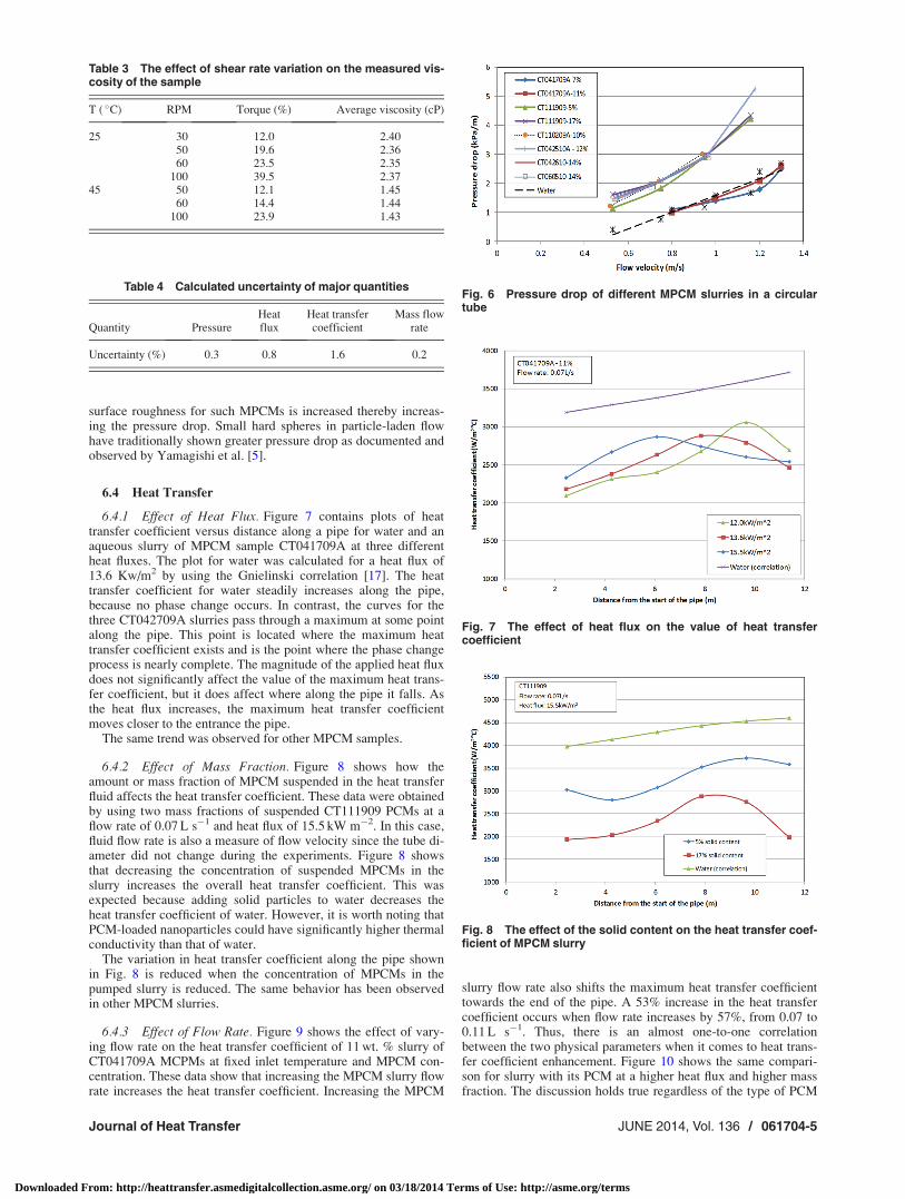
surface roughness for such MPCMs is increased thereby increas-ing the pressure drop. Small hard spheres in particle-laden flowhave traditionally shown greater pressure drop as documented andobserved by Yamagishi et al. [5].
6.4 Heat Transfer
6.4.1 Effect of Heat Flux. Figure 7 contains plots of heattransfer coefficient versus distance along a pipe for water and anaqueous slurry of MPCM sample CT041709A at three differentheat fluxes. The plot for water was calculated for a heat flux of13.6 Kw/m2 by using the Gnielinski correlation [17]. The heattransfer coefficient for water steadily increases along the pipe,because no phase change occurs. In contrast, the curves for thethree CT042709A slurries pass through a maximum at some pointalong the pipe. This point is located where the maximum heattransfer coefficient exists and is the point where the phase changeprocess is nearly complete. The magnitude of the applied heat fluxdoes not significantly affect the value of the maximum heat trans-fer coefficient, but it does affect where along the pipe it falls. Asthe heat flux increases, the maximum heat transfer coefficientmoves closer to the entrance the pipe.
The same trend was observed for other MPCM samples.
6.4.2 Effect of Mass Fraction. Figure 8 shows how theamount or mass fraction of MPCM suspended in the heat transferfluid affects the heat transfer coefficient. These data were obtainedby using two mass fractions of suspended CT111909 PCMs at aflow rate of 0.07 L s�1 and heat flux of 15.5 kW m�2. In this case,fluid flow rate is also a measure of flow velocity since the tube di-ameter did not change during the experiments. Figure 8 showsthat decreasing the concentration of suspended MPCMs in theslurry increases the overall heat transfer coefficient. This wasexpected because adding solid particles to water decreases theheat transfer coefficient of water. However, it is worth noting thatPCM-loaded nanoparticles could have significantly higher thermalconductivity than that of water.
The variation in heat transfer coefficient along the pipe shownin Fig. 8 is reduced when the concentration of MPCMs in thepumped slurry is reduced. The same behavior has been observedin other MPCM slurries.
6.4.3 Effect of Flow Rate. Figure 9 shows the effect of vary-ing flow rate on the heat transfer coefficient of 11 wt. % slurry ofCT041709A MCPMs at fixed inlet temperature and MPCM con-centration. These data show that increasing the MPCM slurry flowrate increases the heat transfer coefficient. Increasing the MPCM
slurry flow rate also shifts the maximum heat transfer coefficienttowards the end of the pipe. A 53% increase in the heat transfercoefficient occurs when flow rate increases by 57%, from 0.07 to0.11 L s�1. Thus, there is an almost one-to-one correlationbetween the two physical parameters when it comes to heat trans-fer coefficient enhancement. Figure 10 shows the same compari-son for slurry with its PCM at a higher heat flux and higher massfraction. The discussion holds true regardless of the type of PCM
Table 3 The effect of shear rate variation on the measured vis-cosity of the sample
T ( �C) RPM Torque (%) Average viscosity (cP)
25 30 12.0 2.4050 19.6 2.3660 23.5 2.35
100 39.5 2.3745 50 12.1 1.45
60 14.4 1.44100 23.9 1.43
Table 4 Calculated uncertainty of major quantities
Quantity PressureHeatflux
Heat transfercoefficient
Mass flowrate
Uncertainty (%) 0.3 0.8 1.6 0.2
Fig. 6 Pressure drop of different MPCM slurries in a circulartube
Fig. 7 The effect of heat flux on the value of heat transfercoefficient
Fig. 8 The effect of the solid content on the heat transfer coef-ficient of MPCM slurry
Journal of Heat Transfer JUNE 2014, Vol. 136 / 061704-5
Downloaded From: http://heattransfer.asmedigitalcollection.asme.org/ on 03/18/2014 Terms of Use: http://asme.org/terms

in the slurry. In Fig. 10, it also shows that the maximum heattransfer coefficient is delayed as the flow rate is increased, whichis in line with observations made by Alvarado et al. [2] and Yama-gishi et al. [5].
6.4.4 Effect of Phase Change Material. The effect of the typeof phase change material on the heat transfer coefficient ofMPCM slurry in a long straight pipe at constant heat flux is shownin Fig. 11. Comparison among different PCM has been made atequal fluid flow rate and heat flux. Comparison with water is alsoshown at the same flow rate. It can be seen from Fig. 11 that thematerial inside the capsules does not have an influence on the heattransfer coefficient of slurry as long as the latent heat of fusionvalue is relatively identical. This is in spite of the fact that thePCM inside the capsules has different melting temperatures forthe samples under comparison in Fig. 11. This was expected sincein general, the effect of adding micrometer sized particles to thebase fluid (water) almost always results in lower heat transfercoefficient values. Note that the CT060510 slurry shows no signif-icant heat transfer coefficient improvement even though it con-tains carbon nanotubes dispersed in the PCMs.
6.5 Effective Heat Capacity. The main advantage of usingphase change material in any heat transfer fluid is the increasedheat capacity inherent with it. Figure 12 is a comparison of theeffective heat capacity of water created by adding to aqueous slur-ries of methyl stearate MPCMs. Equations (1) and (2) were usedto calculate the plots shown. The slurry of CT111909 MPCMs
contained the highest MPCM concentration and requires moreenergy to complete the phase change process. Thus, its phase tran-sition was not complete in the pipe distance shown in Fig. 12. TheCT110209 MPCM slurry has the lowest MPCM concentration andthe smallest peak (8630 J/kg-K). However, this value is still 105%higher than that of water. At the other end of the spectrum,CT042610 and CT060510 behave exactly the same and show the
Fig. 9 The effect of slurry flow rate on the heat transfer coeffi-cient of a 11 wt. % slurry of CT042709A MPCMs
Fig. 10 The effect of slurry flow rate on the heat transfer coeffi-cient of a 17 wt. % CT111909 MPCM slurry
Fig. 11 The effect of the phase change material in the microcapsules on the heat transfer coefficient
Fig. 12 Effective heat capacity of aqueous MPCM slurrieswhere the MPCMs contain the same PCM (methyl stearate)
Fig. 13 Nu correlation for slurries of MPCMs containing as thePCM
061704-6 / Vol. 136, JUNE 2014 Transactions of the ASME
Downloaded From: http://heattransfer.asmedigitalcollection.asme.org/ on 03/18/2014 Terms of Use: http://asme.org/terms

highest peak value of effective specific heat at 28,300 J kg�1 K�1.This is 573% higher than that of water.
A significant increase in apparent heat capacity created by sus-pending MPCMs in a heat transfer fluid was predicted, in a nu-merical system analysis by Taherian and Alvarado [18]. Theycalculated that the effective heat capacity of a MPCM slurry con-taining octadecane could be as high as 21,000 J kg�1 K�1.
6.6 Nondimensional Correlations. Figure 13 is a plot of Nu/Pr0.4 against Re for all MPCM slurries with methyl stearate as theencapsualted PCM. It is an empirical correlation described byEq. (8) fitted by using all the available experimental data shownin Fig. 12 and Eqs. (3)–(6). Equation 8 can be used in the designand analysis of thermal systems where MPCM slurries could beused as heat transfer fluids.
Nu ¼ 0:038Re0:736Pr0:4 (8)
The correlation coefficient for this equation is 0.66 and is validin the range 2400<Re< 7000. The correlation is quite compara-ble with the commonly accepted correlation by Dittus and Boelter[17].
7 Conclusions
This publication summarizes results of durability tests, pres-sure drop measurements, and heat transfer measurementsmade with aqueous slurries of MPCMs under turbulent flowconditions. Durability tests revealed that several thousandcycles of pumping did not have a major detrimental effect onthe effective heat capacity enhancement of the MPCM slurriestested. The magnitude of the applied heat flux did not have asignificant effect on the value of the maximum heat transfercoefficient. Increasing the concentration of MPCMs in theaqueous reduced the value of the heat transfer coefficient ofthe slurry. Increased flow rate not only increased the heattransfer coefficient but also shifted the location of the maxi-mum heat transfer coefficient towards the downstream side ofthe flow. The type of the phase change material in the capsu-les seemed to have negligible effect on the magnitude of theheat transfer coefficient of the slurry as long as PCMs withsimilar mass fraction and latent heat of fusion values areused. In addition, experimental results obtained from thisstudy were used to postulate a Nusselt-based empirical corre-lation, which can be used for design and analysis of thermalsystems.
Nomenclature
cp ¼ specific heat of fluid, J kg�1 K�1
D ¼ tube diameter, mh ¼ heat transfer coefficient, W m�2 K�1
k ¼ thermal conductivity of fluid, W m�1 K�1
L ¼ tube length, m_m ¼ mass flow rate, kg s�1
MF ¼ mass fractionNu ¼ Nusselt numberPr ¼ Prandtl numberP ¼ pressure, kPaQ ¼ heat load, Wq00 ¼ heat flux, W m�2
Re ¼ Reynolds number
T ¼ temperature, K or �Ck ¼ latent heat of fusion, J kg�1
Greek Symbols
D ¼ difference or dropq ¼ density, kg m�3
l ¼ dynamic viscosity (Pa-s)
Subscripts
b ¼ bulks ¼ surface
w ¼ watereff ¼ effective
References[1] Mulligan, J. C., Colvin, D. P., and Bryant, Y. G., 1996, “Microencapsulated
Phase-Change Material Suspensions for Heat Transfer in Spacecraft ThermalSystems,” J. Spacecr. Rockets, 33(2), pp. 278–284.
[2] Alvarado, J. L., Marsh, C., Sohn, C., Phetteplace, G., and Newell, T., 2007,“Thermal Performance of Microencapsulated Phase Change Material Slurry inTurbulent Flow Under Constant Heat Flux,” Int. J. Heat Mass Transfer,50(9–10), pp. 1938–1952.
[3] Chen, B., Wang, X., Zeng, R., Zhang,Y., Wang, X., Niu, J., Li, Y., and Di, H.,2008, “An Experimental Study of Convective Heat Transfer With Microencap-sulated Phase Change Material Suspension: Laminar Flow in a Circular TubeUnder Constant Heat Flux,” Exp. Therm. Fluid Sci., 32(8), pp. 1638–1646.
[4] Kasza, K. E., and Chen, M. M., 1985, “Improvement of the Performance of So-lar Energy or Waste Heat Utilizations Systems by Using Phase-Change Slurryas an Enhanced Heat-Transfer Storage Fluid,” ASME J. Sol. Energy Eng., 107,pp. 229–236.
[5] Yamagishi, Y., Takeuchi, H., Pyatenko, A. T., and Kayukawa, N., 1999,“Characteristics of Microencapsulated PCM Slurry as a Heat-Transfer Fluid,”AIChE J., 45(4), pp. 696–707.
[6] Zhang, S., and Niu, J., 2010, “Experimental Investigation of Effects of Super-cooling on Microencapsulated Phase-Change Material (MPCM) Slurry ThermalStorage Capacities,” Sol. Energy Mater. Sol. Cells, 94(6), pp. 1038–1048.
[7] Wang, X., Niu, J., Li, Y., Zhang, Y., Wang, X., Chen, B., Zeng, R., and Song,Q., 2008, “Heat Transfer of Microencapsulated PCM Slurry Flow in a CircularTube,” AIChE J., 54(4), pp. 1110–1120.
[8] Taherian, H., Alvarado, J. L., and Thies, C., 2010, “Improving Heat TransferEfficiency With an Aqueous Slurry of Microencapsulated Phase Change Mate-rial Under Turbulent Flow Conditions,” 239th ACS National Meeting, SanFrancisco, CA.
[9] Tumuluri, K., Alvarado, J. L., Taherian, H., and Marsh, C., 2011, “Thermal Per-formance of a Novel Heat Transfer Fluid Containing Multiwalled CarbonNanotubes and Microencapsulated Phase Change Materials,” Int. J. Heat MassTransfer, 54(25–26), pp. 5554–5567.
[10] Wang, X., and Niu, J., 2009, “Performance of Cooled-Ceiling Operating WithMPCM Slurry,” Energy Convers. Manage., 50(3), pp. 583–591.
[11] Chamarthy, P., and Utturkar, Y., 2009, “Theoretical Evaluation and Experimen-tal Investigation of Microencapsulated Phase Change Materials (MPCM) inElectronics Cooling Applications,” 25th Annual IEEE SEMI-THERM, SanJose, CA.
[12] Charunyakorn, P., Sengupta, S., and Roy, S. K., 1991, “Forced ConvectionHeat Transfer in Microencapsulated Phase Change Material Slurries: Flow inCircular Ducts,” Int. J. Heat Mass Transfer, 34(3), pp. 819–833.
[13] Bai, F., and Lu, W., 2003, “Numerical Analysis of Laminar Forced ConvectionHeat Transfer in Microencapsulated Phase Change Material Suspensions,” J.Enhanced Heat Transfer, 10(3), pp. 311–322.
[14] Alisetti, E. L., and Roy, S. K., 1999, “Forced Convection Heat Transfer toPhase Change Material Slurries in Circular Ducts,” J. Thermophys., 14(1), pp.115–118.
[15] Kline, S. J., and McClintock, F. A., 1953, “Describing Uncertainties in Single-Sample Experiments,” Mech. Eng., 75(1), pp. 3–8.
[16] Larson, R. G., 1999, The Structure and Rheology of Complex Fluids, OxfordUniversity, New York.
[17] Bergman, T. L., Lavine, A. S., Incropera, F. P., and Dewitt, D. P., 2011, Intro-duction to Heat Transfer, 6th ed., John Wiley & Sons, Hoboken, NJ.
[18] Taherian, H., and Alvarado, J. L., 2010, “System Analysis of MPCM SlurryEnhanced With Carbon Nanotubes as Heat Transfer Fluid,” ASHRAE Trans.,26, AB-10-021.
Journal of Heat Transfer JUNE 2014, Vol. 136 / 061704-7
Downloaded From: http://heattransfer.asmedigitalcollection.asme.org/ on 03/18/2014 Terms of Use: http://asme.org/terms