fluid mechanics of liquid metal batteries · douglas h. kelley department of mechanical...
TRANSCRIPT

Douglas H. KelleyDepartment of Mechanical Engineering,
University of Rochester,
Rochester, NY 14627
e-mail: [email protected]
Tom WeierInstitute of Fluid Dynamics,
Helmholtz-Zentrum Dresden-Rossendorf,
Bautzner Landstr. 400,
Dresden 01328, Germany
e-mail: [email protected]
Fluid Mechanics of Liquid MetalBatteriesThe design and performance of liquid metal batteries (LMBs), a new technology for grid-scale energy storage, depend on fluid mechanics because the battery electrodes and elec-trolytes are entirely liquid. Here, we review prior and current research on the fluidmechanics of LMBs, pointing out opportunities for future studies. Because the technologyin its present form is just a few years old, only a small number of publications have so farconsidered LMBs specifically. We hope to encourage collaboration and conversation byreferencing as many of those publications as possible here. Much can also be learned bylinking to extensive prior literature considering phenomena observed or expected inLMBs, including thermal convection, magnetoconvection, Marangoni flow, interfaceinstabilities, the Tayler instability, and electro-vortex flow. We focus on phenomena,materials, length scales, and current densities relevant to the LMB designs currentlybeing commercialized. We try to point out breakthroughs that could lead to designimprovements or make new mechanisms important. [DOI: 10.1115/1.4038699]
1 Introduction
The story of fluid mechanics research in LMBs begins withone very important application: grid-scale storage. Electrical gridshave almost no energy storage capacity, and adding storage willmake them more robust and more resilient even as they incorpo-rate increasing amounts of intermittent and unpredictable windand solar generation. LMBs have unique advantages as a grid-scale storage technology, but their uniqueness also means thatdesigners must consider chemical and physical mechanisms—including fluid mechanisms—that are relevant to few other batterytechnologies, and in many cases, not yet well-understood. We willreview the fluid mechanics of LMBs, focusing on studies under-taken with that technology in mind, and also drawing extensivelyfrom prior work considering similar mechanisms in other con-texts. In the interest of promoting dialogue across this new field,we have endeavored to include the work of many differentresearchers, though inevitably some would have eluded oursearch, and we ask for the reader’s sympathy for regrettable omis-sions. Our story will be guided by technological application,focusing on mechanisms most relevant to LMBs as built for grid-scale storage. We will consider electrochemistry and theoreticalfluid mechanics only briefly because excellent reviews of bothtopics are already available in the literature. In Sec. 1, we providean overview and brief introduction to LMBs, motivated by thepresent state of worldwide electrical grids, including the varioustypes of LMBs that have been developed. We consider the historyof LMBs in more detail in Sec. 2, connecting to the thermallyregenerative electrochemical cells developed in the middle of thetwentieth century. Then, we consider the fluid mechanisms thatare most relevant to LMBs: thermal convection and magnetocon-vection in Sec. 3, Marangoni flow in Sec. 4, interface instabilitiesin Sec. 5, the Tayler instability in Sec. 6, and electro-vortex flowin Sec. 7. We conclude with a summary and reflection on futuredirections in Sec. 8.
A typical electrical grid spans a country or a continent, servingmillions of consumers by linking them to an intricate network ofhundreds or thousands of large generators. A grid can be under-stood as a single, gigantic machine, because all of its rotating gen-erators must spin in synchrony, and within a fraction of a percent
of their design speed, in order for the grid to function properly.Changes to any one part of the grid affect all parts of the grid. Theimplications of this interconnectedness are made more profoundby the fact that today’s grids have nearly zero storage capacity.When more electricity is being consumed than generated, the con-servation of energy requires that the kinetic energy of the spinninggenerators drops, so they slow down, quickly losing synchrony,damaging equipment, and causing brownouts or blackouts if leftunchecked. Conversely, when more electricity is being generatedthan consumed, generators speed up, risking all the same prob-lems. Fluctuations in demand are as old as electrical utilities andhave historically been managed by continually adjusting supplyby turning generators on and off. Now, grids must also accommo-date fluctuations in supply, as intermittent wind and solar genera-tion expand rapidly because of their plummeting costs and thelong-term imperative that humankind generate a significant shareof our energy using renewable sources [1]. Large-scale storage onelectrical grids would enable widespread deployment of renew-able generation [2,3] while maintaining stability [4]. Many tech-nologies for grid-scale storage have been proposed, includingpumped hydro (which accounts for the vast majority of existingstorage), pressurized air, thermal storage, flywheels, power-to-gas,and batteries. Liquid metal batteries (LMBs) are a particular grid-scale storage technology that comes with interesting fluid mechan-ical challenges.
Like any battery, a liquid metal battery discharges by allowingan energetically favorable chemical reaction to proceed in a con-trolled way. Control is maintained by separating the two reactants(the electrodes) with an electrolyte that prevents electrode materi-als from passing if they are neutral, but allows them to pass if theyare ionized. Thus, the reaction proceeds only if some other pathpasses matching electrons, which then recombine with the ionsand go on to react. The other path is the external circuit whereuseful work is done, thanks to the energy of the flowing electrons.The battery can later be recharged by driving electrons in theopposite direction, so that matching ions come along as well.
Battery electrodes can be made from a wide variety of materi-als, including liquid metals. For example, a liquid sodium nega-tive electrode (anode) can be paired with a sulfur positiveelectrode (cathode) and a solid b-alumina electrolyte. (Here andthroughout, we assign the names “anode” and “cathode” accord-ing to the roles played during discharge.) NajjS batteries operateat about 300 �C and have been deployed for grid-scale storage.ZEBRA batteries [5,6], named for the Zeolite Battery Research
Manuscript received September 14, 2017; final manuscript received November27, 2017; published online January 31, 2018. Assoc. Editor: J€org Schumacher.
Applied Mechanics Reviews MARCH 2018, Vol. 70 / 020801-1Copyright VC 2018 by ASME

Africa Project that developed them, use a NaAlCl4 negative elec-trode that allows them to operate at temperatures as low as245 �C. An electrolyte composed of Na-doped b-alumina conductsNaþ ions. Lower operating temperatures are possible with bat-teries in which a Na negative electrode is combined with a NiCl2positive electrode and a NaAlCl4 electrolyte, separated from thenegative electrode with b-alumina to prevent corrosion. AlloyingCs with the Na can substantially improve wetting to b-alumina,allowing battery operation at still lower temperatures [7]. Sumi-tomo has recently documented a battery design using a eutecticmix of potassium and sodium bis(fluorosulfonyl)amide salts alongwith electrodes made from unspecified sodium compounds [8,9].These battery designs and others like them involve liquid metalsbut require a solid separator between the layers.
As discovered at Argonne National Laboratory in the 1960s[10] and rediscovered at MIT recently [11], batteries can also bedesigned with liquid metal electrodes and molten salt electrolytes,requiring no separator at all. We shall use the term “liquid metalbatteries” to refer to those designs specifically. An example issketched in Fig. 1(a), and cross sections of two laboratory proto-types are shown in Fig. 2. The internal structure of the battery ismaintained by gravity, since the negative electrode materials typi-cally have lower density than electrolyte materials, which have
lower density than positive electrode materials. A solid metal pos-itive current collector contacts the positive electrode and usuallyserves as the container as well. A solid metal negative currentcollector connects to the negative electrode and is electricallyinsulated from the positive current collector.
Because the negative electrode is liquid and the positive currentcollector is also the battery vessel, some care is required to pre-vent shorts between them. It is possible to electrically insulate thepositive current collector by lining it with a ceramic, but ceramicsleeves are too expensive for grid-scale applications and are proneto cracking. Instead, typical designs separate the liquid metal neg-ative electrode from vessel walls with a metal foam, as shown inFig. 2. The high surface tension of the liquid metal provides suffi-cient capillary forces to keep it contained in the pores of the foam.The solid foam also inhibits flow in the negative electrode, whichis likely negligible at length scales larger than the pore size. Inmany designs, the foam is held in place by a rigid conductor, asshown, so that its height stays constant. However, as the batterydischarges and the positive electrode becomes a pool of two-partalloy, it swells. If the positive electrode swells enough to contactthe foam, a short occurs, so the foam height must be carefully cho-sen, taking into account the thickness of the positive electrode andthe density change it will undergo during discharge.
Fig. 1 Sketch of a liquid metal cell with discharge current and density profile for fully chargedstate and isothermal conditions (a) and schematic discharge process (b) from Ref. [12]
Fig. 2 Cross sections of prototype LMBs. Both are enclosed in a stainless steel casing that alsoserves as the positive current collector, and both have a foam negative current collector attachedto a copper conductor that exits the top of the battery. In the discharged state (left), the foam isnearly filled with electrolyte, and a dark Li–Bi intermetallic layer is visible at bottom. In the chargedstate (right), lithium metal is visible in the foam, and the positive electrode at bottom has beenrestored to nearly pure bismuth. Because these photographs were taken at room temperature, theelectrolyte does not fill the volume between the electrodes, but during operation, it would. Thespace above the negative current collector is filled with inert gas during operation. Adapted fromRef. [13], with permission.
020801-2 / Vol. 70, MARCH 2018 Transactions of the ASME

Most liquid metal cells are concentration cells. Their open cir-cuit voltage (OCV) is solely given by the activity of the alkalinemetal in the cathode alloy. The equations for the transfer reactionsat the two interfaces (see Fig. 1(b)) read
M! Mzþ þ ze� (1)
Mzþ þ ze� ! MðNÞ (2)
for the anode/electrolyte interface (1) and the electrolyte/cathodeinterface (2) during discharge. M denotes an alkali (z¼ 1) or anearth-alkali (z¼ 2) metal of the negative electrode, and N refers tothe heavy or half metal of the positive electrode. A variety ofchemistries have been demonstrated, including MgjjSb [14],LijjPb–Sb [15], LijjBi [13], Na|NaCl–CaCl2|Zn [16,17], andCa–MgjjBi [18,19]. (See Ref. [20] for a review.) The LijjPb–Sbchemistry has been studied most and is typically paired with atriple-eutectic LiF–LiCl–LiI electrolyte because of its relativelylow melting temperature (about 341 �C [10,21]). The equilibriumpotentials u0 of both half-cells can be written as
u0 1ð Þ ¼ u00 þRT
zFln
aMzþ
aM
(3)
u0 2ð Þ ¼ u00 þRT
zFln
aMzþ
aMðNÞ(4)
with the standard potential u00, the universal gas constant R, thetemperature T, the Faraday constant F, and the activity a of themetal in the pure (M), the ionic (Mzþ), and the alloyed (M(N))state. The difference of the two electrode potentials u0(2) andu0(1) is the cell’s OCV
EOC ¼ �RT
zFln aMðNÞ (5)
Only the activity of the alkali metal in the alloy aM(N) determinesthe OCV since the standard potentials of both half cells are identi-cal and the activity of the pure anode is one by definition. Undercurrent flow, only the terminal voltage E is available. It is thedifference of OCV and several terms describing voltage losses,i.e., polarizations (cf. [22] and Fig. 1(b)) occurring under current(I) flow
E ¼ EOC � IRE � gc;a � gc;c � ga;a � ga;c (6)
These voltage losses are due to the electrolyte resistance RE, theconcentration polarizations at the anode gc,a and cathode gc,c, andthe corresponding activation potentials ga,a and ga,c. Typically,ohmic losses dominate activation and concentration polarizationsby far, but mass transfer limitations may nevertheless sometimesoccur in the cathodic alloy.
Liquid metal batteries have advantages for grid-scale storage.Eliminating solid separators reduces cost and eliminates the possi-bility of failure from a cracked separator. Perhaps more impor-tantly, solid separators typically allow much slower masstransport than liquids, so eliminating solids allows faster chargeand discharge with smaller voltage losses. Liquid electrodesimprove battery life, because the life of Li-ion and other moretraditional batteries is limited when their solid electrodes aredestroyed due to repeated shrinking and swelling during chargeand discharge. Projections from experimental measurements pre-dict that LijjPb–Sb batteries will retain 85% of their capacity afterdaily discharge for ten years [15]. The LijjPb–Sb chemistry iscomposed of Earth-abundant elements available in quantities largeenough to provide many GWh of storage. Low cost is also criticalif a technology is to be deployed widely [23], and liquid metalbatteries are forecast to have costs near the $100/kWh targetset by the U.S. Advanced Research Projects Agency-Energy(ARPA-e). Their energy and power density are moderate, and
substantially below the Li-ion batteries that are ubiquitous in port-able electronics, but density is less essential than cost in stationarygrid-scale storage. Li-ion batteries today cost substantially morethan $100/kWh, but their costs have dropped continually overtime and will likely drop substantially more as the Tesla GigaFac-tory 1, the world’s largest Li-ion battery plant, continues toincrease its production. The energy efficiency of liquid metal bat-teries varies widely with current density, but at a typical designvalue of 275 mA/cm2 is 73% [15], similar to pumped hydrostorage.
Liquid metal batteries also present challenges. During dis-charge, LijjPb–Sb batteries provide only about 0.8 V [15].Despite variation with battery chemistry, all conventional liquidmetal batteries have voltage significantly less than Li-ion bat-teries. Lacking solid separators, liquid metal batteries are notsuitable for portable applications in which disturbing the fluidlayers could rupture the electrolyte layer, causing electricalshorts between the positive and negative electrodes and destroy-ing the battery. Rupture might also result from vigorous fluidflows even if the battery is stationary, such as the Tayler insta-bility (Sec. 6), interface instabilities (Sec. 5), Marangoni flow(Sec. 4), electro-vortex flow (Sec. 7), or their combination. Flowmechanisms may also interact, triggering instabilities more read-ily. The existing liquid metal battery chemistries require highoperating temperatures (475 �C for LijjPb–Sb). Little energy iswasted heating large batteries because Joule heating (losses toelectrical resistance) provides more than enough energy to main-tain the temperature. Still, high temperatures promote corrosionand make air-tight mechanical seals difficult. Finally, poor mix-ing during discharge can cause local regions of a liquid metalelectrode to form unintended intermetallic solids that can even-tually span from the positive to the negative electrode, destroy-ing the battery. Solid formation may well be the leading causeof failure in liquid metal batteries.
2 History and Past Work
2.1 Three-Layer Aluminum Refinement Cells. The centralidea at the heart of LMBs is the three-layer arrangement of liquidelectrodes and electrolyte. This seemingly simple idea (in fact soapparently simple that it is sometimes [24] questioned if itdeserves to be patented at all) did not originate with LMBs.Instead, using a stable stratification of two liquid metals inter-spaced with a molten salt for electrochemical purposes was firstproposed 1905 by Betts [25] in the context of aluminum purifica-tion (see Fig. 3(b)). However, Betts was not able to commercializehis process. Instead Hoopes, who had a more complicatedarrangement using a second internal vessel for aluminum electro-refining patented in 1901 [26] (Fig. 3(a)), developed later a water-cooled three-layer cell [27] (Fig. 3(c)) that could be successfullyoperated. According to Frary [28], Hoopes as well thought ofusing a three-layer cell around 1900. It can be seen from Table 1that even if the idea to use three liquid layers were a trivial one,its realization and transformation to a working process was highlynontrivial indeed.
The submerged vessel containing the negative electrode, ini-tially suggested by Hoopes [26] (Fig. 3(a)), is filled with moltenimpure aluminum and surrounded by a bath of fused cryolite. Cry-olite is less dense than the pure or impure Al. In the presence offlow, Al dissolves into the cryolite and deposits at the carbonwalls of the outer vessel, and pure Al can be collected at the bot-tom of the outer vessel. However, the current density is distributedvery inhomogeneously, concentrating around the opening of theinner vessel. This implies large energy losses and strong localheating rendering a stable operation over longer times impossible.
Betts [25,29] (Fig. 3(b)) alloyed the impure Al with Cu andadded BaF2 to the cryolite to increase the density of the salt mix-ture and to enable the purified Al to float on the fused salt. Thisthree-layer arrangement guaranteed the shortest possible current
Applied Mechanics Reviews MARCH 2018, Vol. 70 / 020801-3

paths and enabled homogeneous current density distributions.Additionally, the evaporation of the electrolyte was drasticallyreduced by the Al top layer. However, under the high operatingtemperatures the cell walls became electrically conducting, gotcovered with metal that short-circuited the negative and positiveelectrodes, and thus, prevented successful operation of the cell[29].
Only Hoopes’ sophisticated construction [27,28] (Fig. 3(c)) wasfinally able to operate for longer times. A key element of Hoopes’construction is the division of the cell into two electrically insu-lated sections. The joint between them is water cooled and therebycovered by a crust of frozen electrolyte providing electrical aswell as thermal insulation [30]. A similar idea was later applied toNajjBi galvanic cells by Shimotake and Hesson [31]. Addition-ally, instead of using a single electric contact to the purified Al atthe cells’ side as did Betts, Hoopes arranged several graphite cur-rent collectors along the Al surface that provided a more evenlydistributed current. However, the electrolyte used by Hoopes (seeTable 1) had a relatively high melting temperature and a tendencyto creep to the surface between the cell walls and the purifiedAl [28,32]. According to Eger [33] and Beljajew et al. [34] (see aswell Gadeau [35]), the complicated design of Hoopes’ cell, espe-cially the water cooled walls, prevented continuous use in produc-tion. It was not until 1934 that super-purity aluminum becamewidely available with Gadeau’s [36] three-layer refining processthat used a different electrolyte (see Table 1) according to a patentfiled in 1932. Its lower melting point allowed for considerablydecreased operating temperature. Gadeau’s cell was lined withmagnesite that could withstand the electrolyte attack without theneed of water cooling. However, the BaCl2 used in the electrolytemixture decomposed partially, so the electrolyte compositionhad to be monitored and adjusted during cell operation when
necessary. This difficulty was overcome by using the purelyfluoride-based electrolyte composition suggested by Hurter [37](see Table 1, S.A.I.A. process).
Aluminum refining cells can tolerate larger voltage drops thanLMBs, so the electrolyte layer is often much thicker. Valuesquoted are between 8 cm [34,39] that should be a good estimatefor current practice [40], 10 cm [32], 20 cm [41], and 25 cm [38].These large values are, on the one hand, due to the need for heatproduction. On the other hand, a large distance between the nega-tive and positive electrodes is necessary to prevent flow inducedintermixing of the electrode metals that would nullify refinement.It is often mentioned [28,32,38,42] that strong electromagneticforces trigger those flows. Unlike aluminum electrolysis cells(ACEs), refinement cells have been optimized little, and the tech-nology would certainly gain from new research [41]. Yan andFray [41] directly invoke the low density differences as a causefor the instability of the interfaces, discussed here in Sec. 5. Theyattribute the limited application of fused salt electrorefining to thepresent design of refining cells that does not take advantage of thehigh electrical conductivity and the very low thermodynamicpotential required for the process. Coupling optimized electrore-fining to carbon-free generation of electricity should, according toYan and Fray [41], result in “greener” metallurgy.
The application of three-layer processes was also proposed forelectronic scrap reclamation [43], removal of Mg from scrap Al[44–46], and electrorefining of Si [47–49]. Research on the fluidmechanics of current bearing three-layer systems can, therefore,potentially be useful beyond LMBs.
2.2 Thermally Regenerative Electrochemical Systems.After three-layer liquid metal systems were put to use for Al
Fig. 3 Aluminum refinement cells adapted from Hoopes [26] (a), Betts [25] (b), and Drossbach [24] (c)
Table 1 Characteristics of different three-layer aluminum refining processes (approximate values, adapted from Table I of Ref. [38]and Table 6 of Ref. [34])
Hoopes process Gadeau process S.A.I.A. process
Top layer Pure Al Pure Al Pure AlDensity/kgm�3 2290 2300 2300Melting point/�C 660 660 660Electrolyte AlF3–NaF–BaF2 AlF3–NaF–BaCl2–NaCl AlF3–NaF–BaF2–CaF2
Composition (mass%) 0.34–0.28–0.38 0.15–0.17–0.6–0.08 0.48–0.18–0.18–0.16Density/kgm�3 2500 2700 2500Melting point/�C 900 700 670Bottom layer Al–Cu Al–Cu–Other Al–CuComposition (mass%) 0.75–0.25 0.6–0.28–0.12 0.7–0.3Density/kgm�3 2800 3140 3050Melting point/�C 550 Unspecified 590Operating temperature/�C 950 800 750
020801-4 / Vol. 70, MARCH 2018 Transactions of the ASME

refining, a few decades passed before they were used to generateelectricity. In the meantime, related technologies were developed,including “closed cycle battery systems” (Yeager in Ref. [50]),“thermally regenerative fuel cells” or “(thermally) regenerativeelectrochemical systems (TRES)” as they were later subsumed byLiebhafsky [51], McCully et al. [52], and Chum and Osteryoung[53,54]. TRES combine an electricity delivering cell with a regen-eration unit as sketched in Fig. 4: reactants are combined at thelow cell temperature T2, and then the product is thermally decom-posed at the higher regenerator temperature T1. Thermal regenera-tion implies that the whole system efficiency is Carnot limited[55,56].
A variety of such systems were investigated in the U.S. dur-ing the period of 1958–1968 [53]. Later, Chum and Osteryoungclassified the published material on this topic according to sys-tem type and thoroughly reviewed it in retrospect [53,54]. LiH-based cells were building blocks of what were probably thefirst (1958, [53]) experimentally realized thermally regenerativehigh-temperature systems [57–59], which continue to be ofinterest today [60,61]. Almost at the same time a patent wasfiled in 1960 by Agruss [62], bimetallic cells were suggestedfor the electricity delivering part of TRES. Henderson et al.[63] concluded their survey of some 900 inorganic compoundsfor use in thermally regenerative fuel cell systems with the rec-ommendation to concentrate on minimizing electrochemicallosses, i.e., polarization and resistance losses, in order toincrease overall efficiency. Although unmentioned in Ref. [63],bimetallic cells with liquid metal electrodes and fused saltelectrolytes were deemed most suitable to fulfill those require-ments [64]. Governmental sponsored research on bimetalliccells followed soon after at Argonne National Laboratory(1961, [65]) and at General Motors (1962 [64,66]). Researchwas initially focused on the application of bimetallic cell basedTRES on space power applications [67], namely, systems usingnuclear reactors as heat sources. Several studies explored theparameters of concrete designs developed in the frame of“systems nuclear auxiliary power program” (SNAP), SNAP-2[67–71] and SNAP-8 [54].
Hydrodynamics naturally plays a vital role in the operation ofTRES due to the necessity to transport products and reactantsbetween the electricity producing and the thermal regenerationparts of the system. However, hydrodynamics of the transportbetween the cell and the regenerator is mainly concerned withthe task of pumping [69,71] and the subtleties of keeping aliquid metal flow through—while preventing electrical contactbetween—different cells [67]. Velocities typical for TRES aremuch lower than those found in conventional heat engines [72]and could even be achieved using natural circulation driven byheat [10]. Agruss et al. [67] emphasized that the solutal convec-tion should be taken into account when designing TRES cells andthe flow control is vital to obtain good long-term performance.Publications covering detailed investigations of cell specific fluidmechanics are unknown to the present authors, but the LMB
pioneers were obviously aware of its importance as can be seenby a variety of pertinent notes.
Cell construction determines to a large extent the influencehydrodynamics can have on cell operation. No mechanicalobstructions exist in “differential density cell” [54,67–69]sketched in Fig. 5. This is most likely the purest embodimentof an LMB: inside the cell, there are only the three fluid layersthat are floating on top of each other according to density.Early on, the vital role of stable density stratification wasclearly identified [54,69,73]. The interfaces of differential den-sity cells using a K|KOH–KBr–KI|Hg system were stableenough to allow for a mild Hg feed of a few milliliters perminute [67]. Cell performance depended on the flow distribu-tion, the volume flux, and, vicariously, on the temperature ofthe incoming Hg. Cairns et al. [10] presented a conceptualdesign for a battery of three Na|NaF–NaCl–NaI|Bi differentialdensity cells, stressed that the density differences are largeenough to clearly separate the phases, and mentioned in thesame breath that “hydrodynamic stability of the liquid streamsmust be carefully established.”
Restraining one or more of the liquid phases in a porousceramic matrix is a straightforward means to guarantee mechani-cal stability of the interfaces [22]. A direct mechanical separationof anodic and cathodic compartment is a necessity for space appli-cations that could not rely on gravity to keep the layers apart.Besides the solid matrix, another means to immobilize electrolyteswas to intermix them with ceramic powders, the so-called“fillers,” that resulted in paste electrolytes. Since both matrix andpowders had to be electric insulators, an overall conductivityreduction by a factor of about two to four [74,75] resulted evenfor the better paste electrolytes. Obviously, using mechanicallyseparated electrode compartments is a prerequisite for any mobileapplication of LMBs. Equally, for cells used as components incomplete TRES, the constant flow to and from the regenerator andthrough the cell necessitates in almost all cases a mechanical divi-sion of positive and negative electrodes. Examples include theflow through cell with sandwich matrix by Agruss and Karas [69],the earlier single cup cell of “flowing type” using an electrolyteimpregnated alumina thimble [68], and the paste electrolyte cellsdeveloped at Argonne National Laboratory [74,76].
A different purpose was pursued by encasing the negative elec-trode material into a retainer [77] made from stainless steel fibers[10], felt metal [78], or later, foam [13,15,19,79] as sketched inFig. 6. Those retainers allow electrical insulation of the negativeelectrode from the rest of the cell without resorting to ceramicsand restrict fluid mechanics to that in a porous body. The probablysimplest retainer used was an Armco iron ring [10,65] thatencased the alkaline metal, a configuration more akin to the differ-ential density cell than to a porous body. Arrangements similar tothe iron ring are sometimes used as well in molten salt electrolysiscells [27,33,80,81] to keep a patch of molten metal floating on topof fused salt while preventing contact with the rest of the cell. Inthe case of poorly conducting materials (especially Te and Se),the positive electrode had to be equipped with additional
Fig. 4 Closed cycle battery system suggested by Yeager in1957, adapted from Roberts [50]
Fig. 5 Sketch of a differential density cell
Applied Mechanics Reviews MARCH 2018, Vol. 70 / 020801-5

electronically conducting components to improve current collec-tion [22,76].
With view on the low overall efficiencies of TRES due toCarnot cycle limitations as well as problems of pumping, plumb-ing, and separation, research on thermally regenerative systemsceased after 1968 [54] and later LMB work at Argonne concen-trated on Li-based systems with chalcogen positive electrodes,namely, Se and Te. The high strength of the bonds in those sys-tems makes them unsuitable for thermal regeneration [22]. How-ever, in their review, Chum and Osteryoung [54] deemed itworthwhile to reinvestigate TRES based on alloy cells once asolar-derived, high temperature source was identified. Justrecently, a NajjS-based approach for solar electricity generationusing thermal regeneration was suggested [82].
2.3 Liquid Metal Batteries for Stationary Storage. Usingbimetallic cells as secondary elements for off-peak electricitystorage was already a topic in the 1960s [10,83]. The very power-ful LijjSe and LijjTe cells [75] mentioned above are, however,unsuitable for wide scale use because of the scarcity of the bothchalcogens [22,84,85]. In the late 1960s and early 1970s, researchat Argonne moved on to LijjS [22,85–87], thus leaving the area ofbimetallic cells.
LMB activities were reinvigorated at MIT in the first years ofthe 21st century by Donald Sadoway. The initial design conceivedin the fall of 2005 by Sadoway and Ceder and presented byBradwell [88] was one that combined Mg and Sb with a Mg3Sb2-containing electrolyte, decomposing the Mg3Sb2 on charge andforming it on discharge. This new cell design was later termed“Type A” or “ambipolar electrolysis LMB” [89] and not followedup later. Instead, bimetallic alloying cells (“Type B”) were inves-tigated using different material combinations whose selection wasnot hampered by the need of thermal regeneration. The MgjjSbsystem was among the first alloying systems studied at MIT. WithMgCl2–NaCl–KCl (50:30:20 mol%), it used a standard electrolytefor Mg electrolysis [90]. Thermodynamic data for the system areavailable from Ref. [91] and cell performance data were laterreported also by Leung et al. [92].
Right from the start, research at MIT focused on the deploy-ment of LMBs for large-scale energy storage [14] concentratingon different practical and economical aspects of utilizingabundant and cheap materials [18,23]. Initially, large cells withvolumes of a few cubic meters [93] and cross sections of(>2 m� 2 m) [88] were envisioned. Those cells would have afavorable volume to surface ratio translating into a small amountof construction material per active material and potentiallydecreasing total costs. In addition, in large cells, Joule heatingin the electrolyte could be sufficient to keep the componentsmolten [14].
The differential density cells employed for the initial MITinvestigations gave later way to cells that used metal foamimmersed in the electrolyte to contain the negative electrode[13,15,19,79,94].
Successful scaling on the cell level from 1 cm diameter to15 cm diameter was demonstrated by Ning et al. [13]. Commercialcells produced by the MIT spin-off Ambri have square cross sec-tions of 10 cm and 20 cm edge length [95]. Thus, state-of-the-artcells are moderately sized, but the quest for large-scale cells isongoing. Recently, Bojarevics and coworkers [96,97] suggested toretrofit old aluminum electrolysis potlines into large-scale LMBinstallations ending up with cells of 8 m by 3.6 m cross sectionand about 0.5 m total liquid height.
It should be stressed that LMBs form a whole category ofbattery systems comprising a variety of material combinations.Consequently, depending on the active materials and the electro-lyte selected, different flow situations may arise even under identi-cal geometrical settings.
3 Thermal Convection and Magnetoconvection
Because almost every known fluid expands when heated, spatialvariations (gradients) in temperature cause gradients in density. Inthe presence of gravity, if those gradients are large enough, denserfluid sinks and lighter fluid floats, causing thermal convection.Usually, large-scale convection rolls characterize the flow shape.Being ubiquitous and fundamental in engineering and natural sys-tems, convection has been studied extensively, and many reviewsof thermal convection are available [98–101]. Here, we will givea brief introduction to convection, then focus on the particularcharacteristics of convection in liquid metal batteries. Joule heat-ing drives convection in some parts of a liquid metal battery, butinhibits it in others. Broad, thin layers are common, and convec-tion in liquid metal batteries differs from aqueous fluids becausemetals are excellent thermal conductors (that is, they have lowPrandtl number). Convection driven by buoyancy also competeswith Marangoni flow driven by surface tension, as discussed inSec. 4. We close this section with a discussion of magnetoconvec-tion in which the presence of magnetic fields alters convectiveflow.
3.1 Introduction to Thermal Convection. Thermal convec-tion is driven by gravity, temperature gradients, and thermalexpansion, but hindered by viscosity and thermal diffusion. Con-vection also occurs more readily in thicker fluid layers. Combin-ing these physical parameters produces the dimensionlessRayleigh number
Ra ¼ gaTDTL3
�j
where g is the acceleration due to gravity, aT is the coefficientof volumetric expansion, DT is the characteristic temperaturedifference, L is the vertical thickness, � is the kinematic viscos-ity, and j is the thermal diffusivity. The Rayleigh number canbe understood as a dimensionless temperature difference and acontrol parameter; for a given fluid and vessel shape, convectiontypically begins at a critical value Ra>Racrit> 0, and subse-quent instabilities that change the flow are also typicallygoverned by Ra.
If the Rayleigh number is understood as a control parameter,then the results of changing Ra can also be expressed in terms ofdimensionless quantities. The Reynolds number
Re ¼ UL
�(7)
where U is a characteristic flow velocity, can be understood as adimensionless flow speed. The Nusselt number
Nu ¼ � QL
jcpqDT
Fig. 6 Sketch of a liquid metal cell featuring a retainer (metalfoam) to contain the negative electrode
020801-6 / Vol. 70, MARCH 2018 Transactions of the ASME

where Q is the total heat flux through the fluid, cp is the specificheat at constant pressure, and q is the mass density, can be under-stood as a dimensionless heat flux.
The canonical and best-studied context in which convectionoccurs is the Rayleigh–B�enard case, in which a fluid is containedbetween upper and lower rigid, no-slip boundaries, with the lowerboundary heated and the upper boundary cooled. Usually, bothboundaries are held at steady, uniform temperatures, or subjectedto steady, uniform heat flux. Convection also occurs in many othergeometries, for example, lateral heating. Heating the fluid fromabove, however, produces a stably stratified situation in whichflow is hindered.
3.2 Introduction to Compositional Convection. Tempera-ture is not the only parameter that affects fluid density. Chemicalreactions, for example, can also change the local density such thatbuoyancy drives flow. That process is known as compositionalconvection, and the corresponding control parameter is thecompositional Rayleigh number
RaX ¼gaXDXL3
�D
where aX is the coefficient of volumetric expansion with concen-tration changes, DX is the characteristic concentration difference,and D is the material diffusivity. (Compositional convection isone mechanism by which reaction drives flow; entropic heating,discussed earlier, is another.) For liquid metal batteries, the elec-trode materials have densities that differ by more than an order ofmagnitude (see Table 2), and DX� 30 mol %, so we expect com-positional convection to cause substantial flow. For comparison,we can consider thermal convection in bismuth at 475 �C forwhich the coefficient of thermal expansion is aT¼ 1.24� 10�4/K[102]. Making the order-of-magnitude estimate DT� 1 K, itbecomes clear that aXDX� aTDT. For the NajjBi system at anoperating temperature of 475 �C, the compositional Rayleighnumber exceeds the thermal one by six orders of magnitude.Thus, compositional convection is likely much stronger than ther-mal convection. Compositional convection is unlikely during dis-charge because the less-dense negative electrode material (e.g.,Li) is added to the top of the more-dense positive electrode, pro-ducing a stable density stratification. During charge, however,less-dense material is removed from the top of the positive elec-trode, leaving the remaining material more dense and likely todrive compositional convection by sinking.
3.3 Metals and Salts: Convection at Low Prandtl Number.In addition to the Rayleigh number, a second dimensionlessparameter specifies the state of a convecting system, the Prandtlnumber
Pr ¼ �
j
A ratio of momentum diffusivity (kinematic viscosity) to thermaldiffusivity, the Prandtl number, is a material property that can beunderstood as a comparison of the rates at which thermal motionsspread momentum and heat. Table 2 lists the Prandtl number of afew relevant fluids. Air and water are very often the fluids ofchoice for convection studies, since so many industrial and naturalsystems involve them. But air and water have Prandtl numbersthat differ from liquid metals and molten salts by orders of magni-tude: Pr¼ 7 for water and Pr¼ 0.7 for air. We therefore expectthermal convection in liquid metals and molten salts to differ sub-stantially from convection in water or air.
The Prandtl number plays a leading role in the well-knownscaling theory characterizing turbulent convection, developed byGrossmann and Lohse [107]. In fact, the scaling theory expressesthe outputs Re and Nu in terms of the inputs Ra and Pr. To begin,every possible Rayleigh–B�enard experiment is categorizedaccording to the role of boundary layers in transporting momen-tum and heat. Boundary layers occur near walls, and transportthrough them proceeds (to a good approximation) by diffusionalone. On the other hand, in the bulk region far from walls, trans-port proceeds primarily by the fast and disordered motions typicalin turbulent flow. Any particular Rayleigh–B�enard experiment canbe assigned to one of eight regimes, depending on three questions:Is momentum transport slower through the boundary layer or thebulk? Is heat transport slower through the boundary layer or thebulk? And, which boundary layer—viscous or thermal—is thickerand therefore dominant? Answering those three questions makesit possible to estimate the exponents that characterize the depend-ence of Re and Nu on Ra and Pr. According to the theory [107],the Nusselt number can depend on the Prandtl number asweakly as Nu/Pr�1=12 or as strongly as Nu/ Pr1=2, and theReynolds number can depend on the Prandtl number as weakly asRe/Pr�1=2 or as strongly as Re/ Pr�6=7. Again, convection inliquid metals and molten salts differs starkly from convection inwater or air: changing Pr by orders of magnitude causes Re andNu to change by orders of magnitude as well. Experiments study-ing convection in sodium (Pr¼ 0.0107) have confirmed that theheat flux (Nu) for a given temperature difference (Ra) is indeedsmaller than for fluids with larger Pr [108]. Experiments have alsoshown that at low Pr, more of the flow’s kinetic energy is concen-trated in large-scale structures, especially large convection rolls.In a thin convecting layer with a cylindrical sidewall resemblingthe positive electrode of a liquid metal battery, slowly fluctuatingconcentric ring-shaped rolls often dominate [108]. Those rollsmay interact via flywheel effects [109].
3.4 Magnetoconvection. Convection in liquid metal batteriesproceeds in the presence of—and can be substantially alteredby—electric currents and magnetic fields. Introductions and over-views of the topic of magnetoconvection have been provided intexts dedicated to the subject [110] as well as texts on the moregeneral topic of magnetohydrodynamics [111]. The strength of
Table 2 Properties of common electrode materials. Values for metals at respective melting temperature taken from Refs. [103] and[104] except Li conductivity from Ref. [105], Pb–Bi eutectic data from Sobolev [106], and Pb data from Ref. [102].
Material �/10�6 (m2/s) j/10�5 (m2/s) q (kg/m3) aT/10�4 (K�1) rE/106 (S/m) Pr Pm/10�6
Negative electrodeLi 1.162 2.050 518 1.9 3.994 0.0567 5.8315Mg 0.7862 3.4751 1590 1.6 3.634 0.0226 3.5907Na 0.7497 6.9824 927 2.54 10.42 0.0107 9.8195
Positive electrodeBi 0.1582 1.1658 10,050 1.17 0.768 0.0136 0.1527Pb 0.253 1.000 10,673 1.199 1.050 0.0253 0.334Sb 0.2221 1.3047 6483 1.3 0.890 0.0170 0.2485Zn 0.5323 1.5688 6575 1.5 2.67 0.0339 1.7860
Eutectic Pb–Bi 0.3114 0.5982 10,550 1.22 0.909 0.052 0.3557
Applied Mechanics Reviews MARCH 2018, Vol. 70 / 020801-7

the magnetic field can be represented in dimensionless form usingthe Hartmann number
Ha ¼ BL
ffiffiffiffiffiffirE
q�
r(8)
which is the ratio of electromagnetic force to viscous force. Here,B is the characteristic magnetic field strength and rE is the electri-cal conductivity. (Magnetic field strength is also sometimesexpressed using the Chandrasekhar number, which is the squareof the Hartmann number.) When Ha� 1, magnetic fields tend tostrongly alter convection, though the particular effects depend ongeometry. Often, convection rolls align with magnetic field lines,in broad analogy to the tendency of charged particles to orbit mag-netic field lines. Other motions, such as helical paths, are alsopossible.
If convection occurs in the presence of a vertical magnetic field,alignment is impossible, since convection rolls are necessarilyhorizontal. Accordingly, vertical magnetic fields tend to dampconvection [112–114]. The critical Rayleigh number at whichconvection begins scales as Racrit / Ha2 [112], as has been veri-fied experimentally [115]. The Rayleigh number of oscillatoryinstability of convection rolls is also increased by the presence ofa vertical magnetic field [113]. Common sources of vertical mag-netic fields in liquid metal batteries include the Earth’s field(though it is relatively weak) and fields produced by wires carry-ing current to and from the battery.
Just as the Grossmann and Lohse scaling theory [107] considersthe dependence of Re and Nu on the inputs Ra and Pr in convec-tion without magnetic fields, a recent scaling theory by Schu-macher and colleagues [116] considers the dependence of Re andNu on the inputs Ra, Pr—and also Ha—in the presence of a verti-cal magnetic field. The reasoning is analogous: the scalingdepends on whether transport time is dominated by the boundarylayer or the bulk, and which boundary layer is thickest. However,the situation is made more complex by the need to consider mag-netic field transport in addition to momentum and temperaturetransport, and the possibility that the Hartmann (magnetic) bound-ary layer might be thickest. Altogether, 24 regimes are possible.To reduce the number of free parameters, the authors consideredthe case in which Pr � 1 and Pm � 1, where Pm¼ �lrE is themagnetic Prandtl number. (Here, l is the magnetic permeability.)That special case applies to materials common in liquid metalbatteries and still spans four regimes of magnetoconvection. Cate-gorization depends on whether the magnetic field is strong(Ha� 1) and whether the flow is substantially nonlinear (Ra� 1).Scaling laws are proposed for each regime. The theory’s fitparameters remain unconstrained in three of the four regimesbecause appropriate experimental data are unavailable. Experi-ments to produce those data would substantially advance the field.
On the other hand, if a horizontal magnetic field is present, con-vection rolls are often able to align with it easily. In that case,flow speed (Re) and heat flux (Nu) increase [117]. Moreover,since magnetic fields of any orientation damp turbulence [118],convection in the presence of horizontal magnetic fields tends tobe more ordered, spatially, than convection in the Ha¼ 0 case. AsRa increases, waves develop on the horizontal convection rolls[108,113,119].
In liquid metal batteries, internal electrical currents runprimarily vertically and induce toroidal horizontal magnetic fields.Poloidal convection rolls are, therefore, common, since their flowis aligned and circulates around the magnetic field lines. If thesidewall is cylindrical, boundary conditions further encouragepoloidal convection rolls. Such rolls have been observed in liquidmetal battery experiments, and the characteristic speed increasesas Ha increases [120,121]. Simulations have shown similarresults, with the number of convection rolls decreasing as the cur-rent increases [122]. Other simulations, however, have suggestedthat electromagnetic effects are negligible for liquid metal
batteries with radius less than 1.3 m [123,124]. Further study mayrefine our understanding. In batteries with a rectangular cross sec-tion, we would expect horizontal convection rolls circulatingaround cores that are nearly circular near the central axis of thebattery, where the magnetic field is strong and the sidewall isremote. Closer to the wall, we would expect rolls circulatingaround cores that are more nearly rectangular due to boundaryinfluence.
3.5 Convection in Liquid Metal Batteries. Liquid metal bat-teries as sketched in Fig. 7 are a more complicated and interestingcase than a single layer system. Commercially viable liquid metalbattery chemistries involve materials that are solid at room tem-perature; to operate, they must be heated to 475 �C [15]. Externalheaters produce thermal convection in almost any arrangement,especially the most efficient one in which heaters are installedbelow the batteries, producing the Rayleigh–B�enard case. Duringoperation, however, external heaters are often unnecessarybecause the electrical resistance of the battery components con-verts electrical energy to heat in a process known as Joule heatingor ohmic heating. If the battery current is large enough and theenvironmental heat loss is small enough, batteries can maintaintemperature without additional heating [125]. (In fact, coolingmay sometimes be necessary.) In this case, the primary heatsource lies not below the battery, but within it. As Table 3 shows,molten salts have electrical conductivity typically four orders ofmagnitude smaller than liquid metals, so that essentially all of theJoule heating occurs in the electrolyte layer, as shown in Fig. 8.The positive electrode, located below the electrolyte, is thenheated from above and becomes stably stratified; its thermal pro-file actually hinders flow. Some flow may be induced by the hori-zontal motion of the bottom of the electrolyte layer, which slidesagainst the top of the positive electrode and applies viscous shearstresses, but simulations of Boussinesq flow show the effect to beweak [123,124]. The electrolyte itself, which experiences substan-tial bulk heating during battery charge and discharge, is subject tothermal convection, especially in its upper half [124,131]. Onesimulation of an internally heated electrolyte layer showed it to becharacterized by small, round, descending plumes [132]. Experi-ments have raised concern that thermal convection could bringintermetallic materials from the electrolyte to contaminate thenegative electrode [133]. Convection due to internal heating hasalso been studied in detail in other contexts [134].
The negative electrode, located above the electrolyte, is heatedfrom below and is subject to thermal convection. In a negativeelectrode composed of bulk liquid metal, we would expect bothunstable thermal stratification and viscous coupling to the adjacentelectrolyte to drive flow. Simulations show that in parameterregimes typical of liquid metal batteries, it is viscous couplingthat dominates; flow due to heat flux is negligible [123]. There-fore, in the case of a thick electrolyte layer, mixing in the
Fig. 7 Sketch of a liquid metal cell with thermal convection
020801-8 / Vol. 70, MARCH 2018 Transactions of the ASME

electrolyte is stronger than mixing in the negative electrodeabove; in the case of a thin electrolyte layer, the roles are reversed[123]. However, the negative electrodes may also be held in thepores of a rigid metal foam by capillary forces, which preventsthe negative electrode from contacting the battery sidewall [15].The foam also substantially hinders flow within the negative elec-trode. Essentially, the characteristic length scale becomes the poresize of the foam, which is much smaller than the thickness of thenegative electrode. Since the Rayleigh number is proportional to
the cube of the characteristic length scale (Eq. (7)), convection isdrastically weakened, if not prevented altogether. The physics ofconvection in porous media [135,136] might apply in this case.
If a liquid metal battery is operated with current density that isuniform across horizontal cross section, we expect uniform Jouleheating, and therefore, temperatures that vary primarily in the ver-tical direction (aside from thermal edge effects). However, thenegative current collector must not make electrical contact withthe vessel sidewall, which is part of the positive current collector.For that reason, the metal foam negative current collector thatcontains the negative electrode is typically designed to be smallerthan the battery cross section, concentrating electrical current nearthe center and reducing it near the sidewall. The fact that currentcan exit the positive electrodes through the sidewalls as well asthe bottom wall allows further deviation from uniform, axial cur-rent. Nonuniform current density causes Joule heating that is alsononuniform—in fact, it varies more sharply, since the rate of heat-ing is proportional to the square of the current density. This gradi-ent provides another source of convection-driven flow. Puttingmore current density near the central axis of the battery createsmore heat there and causes flows that rise along the central axis.Interestingly, electro-vortex flow (considered in detail in Sec. 7)tends to cause the opposite motion: descent along the central axis.Simulations have shown that negative current collector geometryand conductivity substantially affect flow in liquid metal batteries[137]. Other geometric details can also create temperature gra-dients and drive convection. For example, sharp edges on a cur-rent collector concentrate current and cause intense local heating.The resulting local convection rolls are small but can nonethelessalter the global topology of flow and mixing. Also, if solid inter-metallic alloys form, they affect the boundary conditions thatdrive thermal convection. Intermetallics are typically less densethan the surrounding melt, so they float to the interface betweenthe positive electrode and electrolyte. Intermetallics typicallyhave lower thermal and electrical conductivity than the melt, sowhere they gather, both heating and heat flux are inhibited, chang-ing convection in nontrivial ways.
4 Marangoni Flow
The molecules of a stable fluid are typically attracted morestrongly to each other than to other materials. The result is the sur-face tension (or surface energy) r, which can be understood as anenergy per unit area (or a force per unit length) of interfacebetween two materials. The surface tensions of liquid metals andmolten salts are among the highest of any known materials, so itis natural to expect surface tension to play a role in liquid metalbatteries. This section will consider that role.
If the surface tension varies spatially, regions of higher surfacetension pull fluid along the interface from regions of lower surfacetension. Viscosity couples that motion to the interior fluid, causing“Marangoni flow,” sketched in Fig. 9. Surface tension can varyspatially because it depends on temperature, chemical composi-tion, and other quantities. For most fluids, surface tensiondecreases with temperature: @r/@T< 0, and flow driven by thevariation of surface tension with temperature is called“thermocapillary flow” and is described in existing reviews[138–140]. Thermocapillary flow in the presence of a magneticfield has also been studied in prior work [141,142], though wewill not consider it further here. Flow driven by the variation ofsurface tension with composition, called “solutal Marangoniflow,” has also been considered [143–146], especially in thecontext of thin films [146,147]. In this section, we will considerMarangoni flow phenomena that are relevant to liquid metal bat-teries, focusing on similarities and differences to Marangoni flowsstudied in the past. We will estimate which phenomena are likelyto arise, drawing insight from one pioneering study that has con-sidered the role of thermocapillary flow in liquid metal batteries[131].
Table 3 Properties of common electrolyte materials, from Janzet al. [126,127], Todreas et al. [128], Kim et al. [11], and Massetet al. [129,130]
Material �/10�6 (m2/s) q (kg/m3) rE (S/m)
LiF 1.228 1799 860LiCl 1.067 1490 586LiI 0.702 3.0928 396.68NaCl 0.892 1547 363CaCl2 1.607 2078 205.9BaCl2 1.460 3.150 216.4NaOH 2.14 1767 244NaI 0.532 2725.8 229.2ZnCl2 1150 2514 0.268LiCl–KCl 1.560 1563 157.2(58.5–41.5) mol %NaCl–KCl–MgCl2 0.688 1715 80(30–20–50) mol %LiCl–LiF–LiI — 2690 288(29.1–11.7–59.2) mol %
Fig. 8 A simulation of thermal convection in a three-layer liq-uid metal battery. A vertical cross section through the center ofthe battery (a) shows that the temperature is much higher in theelectrolyte than in either electrode. A horizontal cross sectionabove the electrolyte (b) shows vigorous flow. Here, uz is thevertical velocity component, the radius and thickness of thebattery are 52 mm, and the LiCl–KCl electrolyte makes up 10%of the thickness. Adapted from Ref. [123], with permission.
Applied Mechanics Reviews MARCH 2018, Vol. 70 / 020801-9

4.1 Introduction to Thermocapillary Marangoni Flow.Thermocapillary flow is driven by temperature gradients but hin-dered by viscosity, thermal diffusion, and density (which providesinertia). Thermocapillary flow also occurs more readily in thickerfluid layers. Combining these physical parameters produces thedimensionless Marangoni number
Ma ¼
���� @r@T
����LDT
q�j(9)
The Marangoni number plays a role analogous to the Rayleighnumber in thermal convection. Larger values of Ma make thermo-capillary flow more likely and more vigorous. Because temperaturegradients drive both thermocapillary flow and thermal convection,the two phenomena often occur simultaneously. We can comparetheir relative magnitudes via the dynamic Bond number
Bo ¼ Ra
Ma¼ qaTgL2���� @r@T
����(10)
Thermal convection dominates when Bo� 1, whereas thermoca-pillary flow dominates when Bo � 1. Because of the L2 factor,thermal convection tends to dominate in thick layers, whereasthermocapillary flow tends to dominate in thin layers. Thermoca-pillary flow, like thermal convection, is qualitatively different forfluids with small Prandtl number (like liquid metals and moltensalts) than for fluids with large Prandtl number.
4.2 Temperature Variation Across the Interface. Thermo-capillary flow phenomena depend on the direction of the thermalgradient with respect to the interface. Surface tension varyingalong the interface always drives flow, as shown in Fig. 9. Wewill consider this case in greater detail later. However, thermoca-pillary flow can also occur if temperature varies across the inter-face, with the hotter material having smaller thermal diffusivity.In that case, an instability is possible: local perturbations caneither change the temperature profile along the interface directlyor indirectly through a change to the interface shape, resulting inMarangoni flow. The instability can produce either of two differ-ent phenomena, short-wavelength and long-wavelength thermoca-pillary flow, in which deformations are damped primarily bygravity or diffusion, respectively. The relative strength of the twodamping mechanisms is quantified by the Galileo number
G ¼ gd3
�j(11)
G� 1 implies that gravity is the primary damping mechanism,such that we expect short-wavelength flow, whereas G � 1
implies that diffusion of heat and momentum is the primary damp-ing mechanism, such that we expect long-wavelength flow[140,148]. (Note that some past authors [138,139] have used theterm “Marangoni flow” for the specific case of thermocapillaryflow driven by temperature variation across the interface, not forthe much more general case of all flows driven by surface tension,as we use it here.)
In the G� 1 case, linear stability theory shows that conductiveheat transfer becomes unstable and short-wavelength flow ariseswhen Ma> 80 [149], as experimental studies have confirmed[148]. Typically, short-wavelength flow appears as an array ofhexagons covering the interface. For G � 120, linear stabilitytheory predicts that when Ma> 2G/3, instead of short-wavelengthflow, long-wavelength flow arises [148,150]. The long-wavelength flow has no repeatable or particular shape, insteaddepending sensitively on boundary conditions. When observed inexperiments, the long-wavelength flow always ruptures the layerin which it occurs [139], a property particularly alarming fordesigners of liquid metal batteries. The short-wavelength mode,on the other hand, causes nearly zero surface deformation [139].
We can estimate the relevance of thermocapillary flow and thelikelihood of short-wavelength and long-wavelength flow usingdimensionless quantities, as long as the necessary material proper-ties are well-characterized. Most difficult to obtain is the rate ofchange of surface tension with temperature, @r/@T. Its value iswell-known for Pb, Bi, and their eutectic alloy [102] because ofits importance in nuclear power plants, however. One pioneeringstudy [131] simulated thermocapillary flow in a hypotheticalthree-layer liquid metal battery with a eutectic PbBi positiveelectrode, a LiCl–KCl electrolyte, and a Li negative electrode.First considering the positive electrode, for a PbBi layer withL¼ 20 mm and DT¼ 0.5 K (the conditions used in the study), weexpect no short-wavelength flow because, according to Eq. (9),Ma¼ 14< 80. Nor do we expect long-wavelength flow because,according to Eq. (11), G¼ 6� 107� 120. Now considering aLiCl–KCl electrolyte layer with L¼ 20 mm and DT¼ 6 K (againmatching [131]), we come to different conclusions: Ma¼ 23,000implies vigorous thermocapillary flow, and Bo¼ 9 leads us toexpect thermocapillary flow of speed similar to the thermal con-vection. Because G¼ 4.7� 106, we expect the short-wavelengthmode, not the long-wavelength mode. Finally, we expect minimalflow in the negative electrode if it is contained in a rigid metalfoam. All of these predictions should be understood as prelimi-nary since Eqs. (9)–(11) consider a layer in which only one sur-face is subject to surface tension effects, but the electrolyte layerin a liquid metal battery is subject to surface tension effects onboth upper and lower surfaces.
In fact, though the long-wavelength mode can readily be observedin laboratory experiments with silicone oils [148,151,152], liquidmetals and molten salts typically have much smaller kinematic vis-cosity and thermal diffusivity, yielding large values of G that makethe long-wavelength mode unlikely. Using the Ma> 2G/3 criterionand the appropriate material properties, we find that the long-wavelength mode will appear only for thicknesses 60 lm or less ineither the PbBi or LiCl–KCl layer. Other considerations require boththe electrolyte and the positive electrode to be much thicker, so rup-ture via the long-wavelength thermocapillary mode is unlikely in aliquid metal battery.
We would expect, however, that the short-wavelength thermo-capillary mode often arises in liquid metal batteries, especially inthe electrolyte layer. Though unlikely to rupture the electrolyte,the short-wavelength mode may mix the electrolyte, promotingmass transport. The short-wavelength mode might also couple toother phenomena, for example, the interfacial instabilities dis-cussed in Sec. 5.
4.3 Temperature Variation Along the Interface. Tempera-ture that varies along the interface always drives Marangoni flow,and we can estimate its speed by considering the energy involved.
Fig. 9 Marangoni flow occurs when surface tension at a fluidinterface varies spatially. Variation along the interface alwaysdrives flow, as shown. Variation across the interface, however,causes an instability that drives flow only if the variation is suf-ficiently large, as quantified by the Marangoni number Ma.
020801-10 / Vol. 70, MARCH 2018 Transactions of the ASME

Suppose a thin, rectangular layer of fluid occupies the region0� x � Lx, 0 � y � Ly, 0 � z � Lz in Cartesian coordinates (x, y,z), with Lz� Lx and Lz� Ly. Suppose thermocapillary forces acton the z¼Lz surface, and that temperature varies in the x direc-tion, such that surface tension drives flow in the x direction. Thework done by thermocapillary forces (per unit volume) scales as
DT@r@T
LxLy
LxLyLz
If the flow is steady, if pressure variations are negligible, and ifinertial and gravitational forces are negligible, then the work doneby thermocapillary forces must be dissipated by viscous damping.For an incompressible Newtonian fluid, the viscous damping term(in energy per unit volume) reads
lsuj@2ui
@xi@xjþ @2uj
@xi@xj
!
where we use indicial notation with summation implied, uj is avelocity component, and s is a characteristic flow time. We canestimate the flow time in terms of a characteristic speed U and thetotal circulation distance s� (Lxþ Lz)/U. If there is no flow in they direction and no flow variation in the x direction, we can esti-mate the gradients in the viscous damping term as well. Settingthe result equal to the work (per unit volume) done by capillaryforces and solving for U, we estimate a characteristic speed
U �DT
@r@T
lLz
Lz þ Lx
As expected, the speed increases with DT and @r/@T, whichincreases the thermocapillary force; and increases with Lz,which reduces viscous shear; but decreases with l, Lz, and Lx,which increases viscous drag. Again considering the model of[131], we find U� 0.4 mm/s in the PbBi positive electrode andU� 8 mm/s in the LiCl–KCl electrolyte. Figure 19 in Ref. [131]shows velocities around 2 mm/s, so our velocity scaling argumentseems to predict the correct order of magnitude.
Simulations can give further insight into thermocapillary flowin liquid metal batteries. K€ollner et al. [131] considered a modelliquid metal battery with uniform current density that caused Jouleheating in all three layers, thereby causing both thermocapillaryflow and buoyancy-driven thermal convection. As shown in Fig.10, Marangoni cells are evident at the top of the electrolyte, andthe temperature is much higher in the electrolyte than in eitherelectrode, consistent with Fig. 8. Using a range of layer thick-nesses and current densities, the study found that five modes ofthermal flow arise in typical liquid metal batteries. In order ofdecreasing typical speed, they are (1) thermal convection in theelectrolyte, (2) thermal convection in the negative electrode, (3)thermocapillary flow driven by the top surface of the electrolyte,(4) thermocapillary flow driven by the bottom surface of the elec-trolyte, and (5) anticonvection [153] in the positive electrode. Thecombined effects of buoyant and thermocapillary forces produceflows much like those produced by buoyancy alone, though ther-mocapillary forces slightly reduce the characteristic length scaleof the flow. That observation is consistent with an earlier observa-tion that thermocapillary and buoyant forces drive flows havingdifferent characteristic lengths [151]. In the electrolyte, thermoca-pillary forces always augment buoyant flow, but in the negativeelectrode, thermocapillary forces oppose and substantially dampbuoyant flow when Ma< 200 [131]. Electrolyte layers thinnerthan 2 mm exhibit neither thermocapillary flow nor thermal con-vection for realistic current densities (less than 2000 A/m2). Weraise one caveat: if the negative electrode is contained by a metalfoam, flow there would likely be negligible.
4.4 Introduction to Solutal Marangoni Flow. SolutalMarangoni flow has been studied less than thermocapillary flow,and to our knowledge, has not yet been addressed in the literaturefor the specific case of liquid metal batteries. One experimentaland numerical study found a cellular flow structure reminiscent ofthe hexagons characteristic of the short-wavelength mode in ther-mocapillary flow [144]. A later experimental and numerical studyby the same authors [145] varied the thickness of the fluid layerand its orientation with respect to gravity, finding that a two-dimensional simulation in which flow quantities are averagedacross the layer thickness fails to match experiments with thicklayers. The study also found that cells coarsen over time, perhapsscaling as t1=2, where t is the time.
Though studies of solutal Marangoni flow in liquid metal bat-teries have not yet been published, the phenomenon is likely,because charge and discharge alter the composition of the positiveelectrode. In past work, salt loss in lithium-chalcogen cells hasbeen attributed to Marangoni flow [154]. In the case where com-position varies across the interface, solutal Marangoni flow is pos-sible only if material flows across the interface in the direction ofincreasing material diffusivity. In a liquid metal battery, the mate-rial of interest is the negative electrode material, e.g., Li, and theinterface of interest is the one between molten salt electrolyteand liquid metal positive electrode. The diffusivity of Li in Bi is
Fig. 10 A simulation of Marangoni flow in a three-layer liquidmetal battery. Temperature is indicated in color, and velocity isindicated by arrows. The horizontal top surface of the electro-lyte shows Marangoni cells (a) with downwellings where thetemperature is lowest. A vertical cross section through the cen-ter of the battery, (b) also shows downwellings and indicatesthat the temperature is much higher in the electrolyte than ineither electrode. Here, a LiCl–KCl electrolyte separates a Li neg-ative electrode from a PbBi positive electrode. The temperatureunit is 6.59 K, the velocity unit is 6.46 3 1026 m/s, and the lengthunit is 20 mm. Adapted from Ref. [131], with permission.
Applied Mechanics Reviews MARCH 2018, Vol. 70 / 020801-11
1.2� 10�8 m2/s, and the diffusivity of Li in LiBr–KBr has beencalculated as 2.4� 10�9 m2/s [155]. A battery made with thosematerials would be prone to solutal Marangoni flow driven bycomposition varying across the interface during discharge, but notduring charge. Solutal Marangoni flow driven by variations acrossthe interface is likely to occur in both short- and long-wavelengthmodes, depending on the appropriate Marangoni and Galileo num-bers (analogous to Eqs. (9) and (11)). However, a two-layer modelfor solutal Marangoni flow is unstable at any value of the Maran-goni number [138,156]. Variations of composition along the inter-face will drive solutal Marangoni flow regardless of their values.
An estimate of the magnitude of solutal Marangoni flow wouldbe useful. Even less is known about the rate of change of surfacetension with composition than about the rate of change with tem-perature. Still, we can put an upper bound on the magnitude ofsolutal Marangoni flow, and compare to thermocapillary flow, byconsidering extreme cases. The force per unit length that drivesthermocapillary flow is ���� @r@T
DT
����Again considering the same situation as [131], we find a force perunit length around 1.8� 10�4 N/m. The force per unit length thatdrives solutal Marangoni flow is���� @r@X
DX
����Unfortunately, @r/@X is, to our knowledge, unknown in the litera-ture for materials common to liquid metal batteries. Alternatively,we can consider the extreme case in which different regions of theinterface are composed of different pure materials, so that theforce per unit length is simply the difference between their(known) surface tensions. Using rPbBi¼ 0.4086 N/m at 500 K[102], rLi¼ 0.396 N/m at 453 K [105], and rLiCl–KCl¼ 0.122 N/mat 823 K [157], we find rPbBi – rLi¼ 1.3� 10�2 N/m and rLi –rLiCl–KCl¼ 2.7� 10�1 N/m. These estimates are imprecise:considering temperature will change them by a few percent, andconsidering different battery chemistry will change them more.These estimates are also upper bounds. Nonetheless, these esti-mates are two to four orders of magnitude larger than the typicalforce per unit length that drives thermocapillary flow. If the truesolutal forces reach even a few percent of these estimates, solutalMarangoni flow rivals or dominates thermocapillary flow in liquidmetal batteries. Better constraints on the magnitude of solutalMarangoni flow—beginning with estimates of @r/@X—would bea valuable contribution for future work.
5 Interface Instabilities
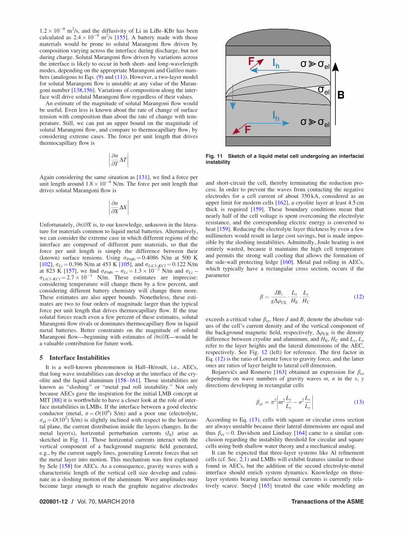
It is a well-known phenomenon in Hall–H�eroult, i.e., AECs,that long wave instabilities can develop at the interface of the cry-olite and the liquid aluminum [158–161]. Those instabilities areknown as “sloshing” or “metal pad roll instability.” Not onlybecause AECs gave the inspiration for the initial LMB concept atMIT [88] it is worthwhile to have a closer look at the role of inter-face instabilities in LMBs. If the interface between a good electricconductor (metal, r¼O(106) S/m) and a poor one (electrolyte,rel¼O(102) S/m) is slightly inclined with respect to the horizon-tal plane, the current distribution inside the layers changes. In themetal layer(s), horizontal perturbation currents (Ih) arise assketched in Fig. 11. Those horizontal currents interact with thevertical component of a background magnetic field generated,e.g., by the current supply lines, generating Lorentz forces that setthe metal layer into motion. This mechanism was first explainedby Sele [158] for AECs. As a consequence, gravity waves with acharacteristic length of the vertical cell size develop and culmi-nate in a sloshing motion of the aluminum. Wave amplitudes maybecome large enough to reach the graphite negative electrodes
and short-circuit the cell, thereby terminating the reduction pro-cess. In order to prevent the waves from contacting the negativeelectrodes for a cell current of about 350 kA, considered as anupper limit for modern cells [162], a cryolite layer at least 4.5 cmthick is required [159]. These boundary conditions mean thatnearly half of the cell voltage is spent overcoming the electrolyteresistance, and the corresponding electric energy is converted toheat [159]. Reducing the electrolyte layer thickness by even a fewmillimeters would result in large cost savings, but is made impos-sible by the sloshing instabilities. Admittedly, Joule heating is notentirely wasted, because it maintains the high cell temperatureand permits the strong wall cooling that allows the formation ofthe side-wall protecting ledge [160]. Metal pad rolling in AECs,which typically have a rectangular cross section, occurs if theparameter
b ¼ JBz
gDqCE
Lx
HE
Ly
HC
(12)
exceeds a critical value bcr. Here J and Bz denote the absolute val-ues of the cell’s current density and of the vertical component ofthe background magnetic field, respectively, DqCE is the densitydifference between cryolite and aluminum, and HE, HC and Lx, Ly
refer to the layer heights and the lateral dimensions of the AEC,respectively. See Fig. 12 (left) for reference. The first factor inEq. (12) is the ratio of Lorentz force to gravity force, and the latterones are ratios of layer height to lateral cell dimension.
Bojarevics and Romerio [163] obtained an expression for bcr
depending on wave numbers of gravity waves m, n in the x, ydirections developing in rectangular cells
bcr ¼ p2
����m2 Ly
Lx� n2 Lx
Ly
���� (13)
According to Eq. (13), cells with square or circular cross sectionare always unstable because their lateral dimensions are equal andthus bcr¼ 0. Davidson and Lindsay [164] came to a similar con-clusion regarding the instability threshold for circular and squarecells using both shallow water theory and a mechanical analog.
It can be expected that three-layer systems like Al refinementcells (cf. Sec. 2.1) and LMBs will exhibit features similar to thosefound in AECs, but the addition of the second electrolyte-metalinterface should enrich system dynamics. Knowledge on three-layer systems bearing interface normal currents is currently rela-tively scarce. Sneyd [165] treated the case while modeling an
Fig. 11 Sketch of a liquid metal cell undergoing an interfacialinstability
020801-12 / Vol. 70, MARCH 2018 Transactions of the ASME

electric-arc furnace, assuming a density of zero for the upperphase and the semi-infinite upper and lower layers. He took onlythe azimuthal magnetic field produced by the current into accountand did not consider the action of an additional background field.In addition to long-wave instabilities, Sneyd predicted short-waveinstabilities of both sausage and kink type. To the best of ourknowledge, experimental results on current-driven interface insta-bilities in three-layer systems have not been reported to date. Thecause of the violent motions reported by several authors[28,38,32,42], and already mentioned in Sec. 2.1, is uncertain.Frary [28] describes the motion as swirling and attributes it to theinteraction of the vertical current within the cell and the magneticfields of the horizontal current leads. To prevent intermixing ofthe negative and positive electrodes, the electrolyte layer has to beas thick as 25 cm. This is costly in terms of energy but tolerable ifthe cell is operated as an electrolytic cell. In galvanic mode, OCVobviously limits the permissible current and the resistance of thickelectrolyte layers is prohibitive. For LMBs to have an acceptablevoltage efficiency, the electrolyte thickness must not exceed a fewmillimeters, so maintaining interface stability is more difficult.
Zikanov [166] was the first to discuss sloshing behavior inthree-layer systems explicitly addressing LMBs. He used amechanical analog inspired by Davidson and Lindsay’s [164]movable aluminum plate model for the basic features of sloshingin AECs. Instead of one plate mimicking the aluminum layer ofan AEC, Zikanov assumed two slabs of solid metals to be sus-pended as pendula above and below the electrolyte layer [124].This model replaces the hydrodynamic problem by a systempossessing only four degrees-of-freedom associated with the two-dimensional oscillations of each pendulum. The Lorentz force dueto the interaction of the vertical background magnetic field andthe horizontal currents can cause an instability if
CA
JBzL2x
12gqAHEHA
þ CC
JBzL2x
12gqCHEHC
>
����1� x2x
x2y
���� (14)
Here CA and CC are constants of order one that account forgeometry [166], and qA and qC denote the densities of the nega-tive and positive electrodes, respectively. The pendula oscillatewith their natural gravitational frequencies xx and xy. Again, it isevident from Eq. (14) that circular or square cross sections arepredicted to be always unstable.
Zikanov [166] and Zikanov and Shen [124] discussed anadditional instability that may arise even in the absence of a back-ground magnetic field due to the interaction of J-generated azi-muthal magnetic field Bu with the current perturbations. He findsthe system to be unstable if
l0J2D2
64g
D2
12qAHAH2E
þ D2
12qCHCH2E
þ 1
qAHE
� 1
qCHE
!> 1 (15)
As estimated by Zikanov [166], for rectangular cells, the instabil-ity due to the interaction of the perturbation currents with theazimuthal field of the main current described by criterion (15)appears to be more dangerous than that caused by the action of thebackground magnetic field on the horizontal compensatingcurrents (14).
It should be mentioned that criteria predicting instability onsetfor any nonvanishing Lorentz force neglect dissipative effectscaused by magnetic induction and viscosity as well as the influ-ence of surface tension [167].
Weber et al. [167,168] investigated the metal pad roll instabilityin an LMB using a volume-of-fluid method adapted from the finitevolume code OpenFOAM [169] and supplemented by electromag-netic field calculations to solve the full Navier–Stokes equations.The material properties correspond to the special case of theMg|KCl–MgCl2–NaCl|Sb system (see Table 4 for an overview oftypical systems).
As expected, if one interface is set in motion and the otherremains nearly at rest, a criterion similar to the Sele criterion (12)can be formulated
b ¼ JBzD2
g qE � qAð ÞHAHE
> bcr (16)
using the density differences between negative electrode and elec-trolyte and the respective layer heights. Sloshing in circularcells sets in above a relatively well-defined bcr,sloshing¼ 0.44.Short-circuiting needs more intense Lorentz forces andhappens above bcr,short-circuit 2.5. The validity of both valuesis limited to the MgjjSb system and to the aspect ratiosHA/D¼ 0.45 and HE/D¼ 0.1 investigated by Weber et al. [167],see Fig. 13.
Bojarevics and coworkers [96,97] numerically investigated theMgjjSb system as well, but used a shallow water approximationcombined with the electromagnetic field equations. They consid-ered a cell with a 8� 3.6 m2 cross section, and Mg and Sb layersboth 20 cm in height divided by a 5 or 8 cm thick electrolyte. In
Table 4 Coupling parameter Ag calculated for different possible working material combinations. The densities are reported atworking temperature Top, adapted from Ref. [170].
Electrodes Electrolyte Top (�C) qA qE (kg m�3) qC Ag
Strongly coupled LijjSe LiCl–LiF–LiI 375 497 2690 3814 0.51AljjAl–Cu* AlF3–NaF–CaCl2–NaCl 800 2300 2700 3140 1.1
LijjTe LiCl–LiF–LiI 475 489 2690 5782 1.41
Weakly coupled NajjSn NaCl–NaI 625 801 2420 6740 2.67LijjBi LiCl–LiF–LiI 485 488 2690 9800 3.22NajjBi NaCl–NaI–NaF 550 831 2549 9720 4.18KjjHg KBr–KI–KOH 250 640 2400 12,992 6.02
Not coupled CajjSb CaCl2–LiCl 700 1401 1742 6270 13.28CajjBi CaCl2–LiCl 550 1434 1803 9720 21.43MgjjSb KCl–MgCl2–NaCl 700 1577 1715 6270 33.06
Fig. 12 Characteristic dimensions and notations for an alumi-num electrolysis cell (left) and a liquid metal battery (right)
Applied Mechanics Reviews MARCH 2018, Vol. 70 / 020801-13

agreement with the results of Weber et al. [167,168], Bojarevicsand coworkers [96,97] found the interface between negative elec-trode and electrolyte to be much more sensitive to the instabilitythan the interface between the electrolyte and positive electrode.The difference is explained by density differentials: the electrolytetypically has density closer to that of the negative electrode thanthe positive electrode. Bojarevics and Tucs [97] further optimizedthe magnetic field distribution around the LMB by reusing a com-mercial Trimet 180 kA cell series in their simulation. While theunoptimized cell could only be stabilized for the 8 cm thick elec-trolyte, the optimized cell was able to operate with 2.5 cm electro-lyte height. However, even in the latter case, the voltage drop inthe electrolyte is still found to be excessive with 0.49 V at acurrent of 100 kA.
Horstmann et al. [170] investigated the wave coupling dynam-ics of both interfaces by applying potential theory as well as directnumerical simulations to LMBs with circular cross section. Whileinterface tension should be taken into account for (very) smallcells and large wave numbers, it is negligible in the limit of large-scale LMBs. There, the waves are purely gravitational ones andthe strength of their coupling depends only on the ratio of the den-sity differences
Ag ¼qC � qE
qE � qA
(17)
Thus, for practical cases, Ag is the control parameter that deter-mines how strongly both interfaces interact. Wave onset isdescribed by Sele-like parameters extended by interface tensionterms for both interfaces. The expressions reduce to the Sele crite-rion (16) in the limit of large LMBs considered here.
At the same time, Ag describes for thin electrolyte layers(HE ! 0) the ratios of amplitudes and frequencies of the (anti-phase) waves ���� gmn
AE
gmnEC
���� ¼ x2EC
x2AE
¼ Ag (18)
Here gmnAE and gmn
EC denote the amplitudes of the of the waves at theAE and EC interfaces, respectively, with the azimuthal wave
number m and the radial wave number n. xAE and xEC are thecorresponding frequencies.
The waves at both interfaces can be considered as coupled in therange 0:1 < Ag < 10. If the metal layer with density more similar tothe electrolyte is thinner, the limiting values have to be corrected bythe metal layer height ratio HC/HA. The coupled regime can be furtherdivided into “weakly coupled” (0:1 < Ag � 0:7; 2 �Ag < 10) and“strongly coupled” (0:7�Ag�2) regimes. The threshold values areempirical. In the weakly coupled regime, the interface waves are anti-phase (see Fig. 14) and corotate in the direction determined by themore prominent wave. Dynamics in the strongly coupled regime aremore complex. For moderate b 1.6, both metals rotate in oppositedirections deforming the electrolyte layer into a bulge (“bulge insta-bility”). Higher b (3.2) leads to in phase rotating metal pads(“synchronous tilting instability”). These strongly coupled instabilitiesmay not occur in cells that are not circular, however. Note that bshould be calculated with the densities and length scales correspond-ing to the smaller density jump. This happened always at the upperinterface for the examples discussed earlier. Thus, Eq. (16) coulddirectly be applied.
While the two strongly coupled LMB types (LijjTe and LijjSe)have limited practical relevance due to the scarcity of their posi-tive electrode materials, three-layer refinement cells are almostalways strongly coupled. Gesing et al. [45,46] formulate it as acharacteristic of their Mg-electrorefinement method that the elec-trolyte has to have a density halfway between that of Al and Mg,i.e., they require a coupling parameter Ag ¼ 1.
Zikanov [171] used the St. Venant shallow water equations com-plemented by electromagnetic force terms to model the rolling padinstability in LMBs with rectangular cross sections. In accordancewith Horstmann et al. [170], Zikanov [171] found that the wavedynamics depend on the ratio of the density jumps at both interfa-ces. If the density jump at one interface is much smaller than at theother, only the former develops waves, and the situation is verysimilar to that in AECs. In particular, the influence of the horizontalaspect ratio Lx/Ly on the critical value of the Sele criterion is quitestrong and resembles the situation in AECs. This strong effect canbe explained by the fact that the aspect ratio determines the set ofavailable natural gravitational wave modes and the strength of theelectromagnetic field that is needed to transform them into a pairwith complex-conjugate eigenvalues [164,171].
For comparable density jumps at the interfaces, Zikanov’s[171] results again agree with those of Horstmann et al. [170] inthat both interfaces are significantly deformed. The system behav-ior becomes more complex and is different from that found inAECs. The waves of both interfaces can couple either in phase orantiphase. Zikanov [171] found examples where the presence ofthe second interface stabilizes the system, which was not pre-dicted by his two-slab model [166], whose simplifications areprobably too strong to capture this part of the dynamics.
6 Tayler Instability
Electric currents induce magnetic fields and interact with thosefields, sometimes bringing unexpected consequences. Suppose
Fig. 13 Minimum electrolyte layer height hmin depending on baccording to Eq. (16) for the Mg|KCl–MgCl2–NaCl|Sbsystem, determined in simulations. For each curve, only theparameter named in the legend is varied, the other ones stayconstant (j 5 1 A/cm2, Bz 5 10 mT, HA 5 4.5 cm, HE 5 1 cm, andqA 5 1577 kg/m3). By definition, DqEA 5 qE – qA. The inset showsa snapshot of the anode-electrolyte interface for b 5 2.5.Adapted from Ref. [167].
Fig. 14 In phase and antiphase sloshing waves. Simulatedinterface shapes (top) and idealized circumferential wave con-tours (bottom). Adapted from Ref. [170].
020801-14 / Vol. 70, MARCH 2018 Transactions of the ASME

that a current runs axially and has azimuthally symmetric currentdensity J, as sketched in Fig. 15. Then, by the right-hand rule, itinduces a magnetic field Bu that is purely in the azimuthal direc-tion and interacts with that field to cause a Lorentz force per unitvolume FL ¼ J � Bu directed radially inward. That force can beunderstood as a magnetic pressure. If the current flows through afluid that is incompressible, we might expect the magnetic pres-sure to have no effect. However, Tayler [172,173] and Vanda-kurov [174] showed that if the fluid is inviscid (�¼ 0) and aperfect conductor (rE¼1), and the induced magnetic fieldsatisfies
@
@rrB2
u
� �< 0 (19)
then the stagnant system is unstable. Given an infinitesimal pertur-bation, the current drives fluid flow, initially with azimuthal wavenumber m¼ 1. That phenomenon, known as the Tayler instabilityin astrophysics and as the kink instability in plasma physics, mustalso be considered for liquid metal batteries, which supports largeaxial currents.
In stars, the Tayler instability can in theory overcome gravita-tional stratification to drive dynamo action, and has therefore beenproposed as a source of stellar magnetic fields [175]. In fusionplasma devices, the kink instability [176] can disrupt the magneticfields that prevent plasma from escaping and must therefore beavoided. First encountered in z-pinch experiments in the 1950s,the kink instability has been studied extensively and reviewed inthe plasma physics literature (e.g., Ref. [177]).
Soon after liquid metal batteries were proposed for grid-scalestorage, Stefani et al. [178] observed that the technology would besusceptible to the Tayler instability, and that if the resulting flowwere strong enough, it could cause rupture the electrolyte layer,destroying the battery. Their observation prompted a series ofstudies considering methods to avoid the Tayler instability in liq-uid metal batteries and the likelihood of it causing rupture.
The Tayler instability can be avoided or damped using a varietyof techniques. First, in a real fluid with nonzero viscosity andimperfect electrical conductivity, the onset criterion given byEq. (19) is no longer strictly correct, because viscosity and resist-ance damp the instability, so that it occurs only if the total current(or Hartmann number) exceeds a nonzero critical value. Second,the instability can be avoided by cleverly routing the battery currentto prevent the condition expressed by Eq. (19). Instead of buildinga cylindrical liquid metal battery carrying an axial current, one canbuild a battery that is a cylindrical annulus, with an empty centralbore. Carrying no current, the bore does not contribute to theinduced magnetic field Bu, so that a larger current is requiredbefore onset [178]. Even better is to route the battery current backthrough the bore in the opposite direction, which prevents the Tay-ler instability altogether, since Eq. (19) is never satisfied [178,179].
However, ohmic losses in the wire would reduce the available volt-age. Third, shearing the fluid azimuthally can damp the Taylerinstability [180], though imposing shear is more practical in plasmadevices than in liquid metal batteries. Fourth, imposing externalmagnetic fields—either axial or transverse—damps the Taylerinstability [179], in a process often compared to the damping ofthermal convection by vertical magnetic fields [112,114]. Finally,rotation also damps the Tayler instability [181], though imposingrotation may be impractical for liquid metal batteries.
A variety of engineering solutions to avoid or damp the Taylerinstability in liquid metal batteries are now known. The character-istics of the Tayler instability, and the particular situations inwhich it arises, have also been studied extensively in recent work.The instability was observed directly in a laboratory experiment:when the axial current applied to a cylindrical volume of GaInSnalloy exceeded a critical value, the induced axial magnetic fieldwas observed to grow as the square root of the current [182].Below the critical current, which nearly matched earlier numericalpredictions [183], no axial field was induced. A central bore wasadded to the vessel, and as expected, the critical current grew withbore size, ranging from about 2500 A to about 6000 A. Flow dueto the Tayler instability was found to compete with thermal con-vection caused by Joule heating (see Sec. 3).
A series of numerical studies have also considered the Taylerinstability, with the benefit of being able to characterize its prop-erties in detail. Initial simulations with purely axial current andperfectly conducting boundaries found the Tayler instability tooccur at Ha� 20 [181,184,185]. (The Hartmann number (seeEq. (8)) is known to control onset [183].) Using parameters simi-lar to experiments [182], the simulations found similar criticalcurrents. The simulations also demonstrated the importance ofaspect ratio: liquid metal layers with high aspect ratio (narrow andtall) are more susceptible to the Tayler instability [185], seeFig. 16. Simulations have also shown the effectiveness of engi-neering solutions for avoiding or damping the Tayler instability,including adding a central bore, routing current through the borein the opposite direction, and applying axial or transverse mag-netic fields [179]. The Tayler instability breaks chiral symmetryduring its growth [184] and might therefore provide a linkbetween the planetary tides and the solar cycle [186]. By allowingfor current that is not purely axial, and boundaries that are notperfect conductors, a later simulation [137] incorporated morerealistic current collectors and considered their effects. Currentcollectors with lower conductivity damp the Tayler instability, asdo fluids with lower conductivity [137]. That study also found,however, that electro-vortex flows (see Sec. 7) may play a largerrole in the fluid mechanics of liquid metal batteries than the Tay-ler instability. A numerical linear stability analysis of the Taylerinstability found critical currents consistent with prior work anddescribed the instability as an edge effect, governed by curvatureof the magnetic field [187]. Finally, another simulation studyfound that the Tayler instability occurs in Mg-based liquid metalbatteries with current density J¼ 300 mA/cm2 (a value typical forbatteries being commercialized) if the battery radius exceeds0.43 m and causes rupture if the radius exceeds 3 m [188]. Thoughthere are economic advantages to increasing battery size, we areunaware of prototypes that large.
To summarize: The Tayler instability is a magnetohydrodynamicphenomenon that drives flow when a large axial current passesthrough liquid metal. Because of the magnitude of the currentsinvolved, and because today’s liquid metal battery designs havelarge aspect ratio, the Tayler instability may not yet affect the tech-nology. For larger, next-generation batteries, however, the Taylerinstability should be considered carefully. A variety of engineeringsolutions to avoid or damp the instability are now known.
7 Electro-Vortex Flow
The Tayler instability discussed in Sec. 6 is an interaction of anelectrical current with the magnetic field produced by the current
Fig. 15 Sketch of a liquid metal cell susceptible to the Taylerinstability
Applied Mechanics Reviews MARCH 2018, Vol. 70 / 020801-15

itself. If condition (19) is satisfied and enough current runs, theinstability drives flow even in the case of a purely axial,azimuthally symmetric current. Currents of other shapes can alsointeract with their own magnetic fields to produce forces. In par-ticular, if the Lorentz force produced by self-interaction has non-zero curl, a conductive fluid flows even with arbitrarily weakcurrents in the absence of perturbations. The phenomenon, knownas “electro-vortex flow,” has been reviewed in detail [189] and iscommonly studied in the context of vacuum arc remelting[111,190]. Here, we will give a brief overview and consider theimplications of electro-vortex flow for liquid metal batteries.
To show that a Lorentz force with nonzero curl drives flow, weconsider the conservation of momentum of an incompressibleNewtonian fluid acted upon by a force per unit mass F
@u
@tþ u $ð Þu ¼ � 1
q$pþ �r2uþ F
Here, u is the fluid velocity. It follows that stagnant fluid (u ¼ 0)conserves momentum if and only if
1
q$p ¼ F (20)
One example, of course, is the gravitational force F ¼ �gz, wherewe take z as vertical. In that case, Eq. (20) may be integrateddirectly, yielding the familiar fact that the hydrostatic pressure adistance h below the fluid surface is p¼ qgh. On the other hand, if$� F 6¼ 0, Eq. (20) has no solution, since the curl of a gradient isalways zero. In that case, we conclude that our assumption u ¼ 0was false, that is, if a fluid is acted upon by a force F for which$� F 6¼ 0, the fluid must flow.
If we are interested in the Lorentz force per unit volumeF ¼ J � B due to interaction of an electrical current with its ownmagnetic field, and under the simplifying assumption that allquantities are azimuthally symmetric, it can be shown [189] that$� F 6¼ 0 simplifies to
@Bu
@z6¼ 0
The magnetic field Bu depends, via the Biot–Savart law, on thecurrent density J. So in azimuthally symmetric systems like cylin-drical liquid metal batteries, electro-vortex flow occurs when Jvaries axially. In fact, it can be shown that any divergent currentdensity in an axisymmetric system causes electro-vortex flow.One canonical example is flow driven by a current from the centerof a hemisphere to the hemisphere’s surface [189]. Taking the
additional assumption that the resulting flow is irrotational allowsanalytical solution of many other cases as well. However, manyare similarity solutions for which boundary conditions are eval-uated at infinity, hindering their application to technological appli-cations like liquid metal batteries.
The details of electro-vortex flow are typically studied via sim-ulation or experiment. Flows typically converge where the currentdensity is highest, causing the largest magnetic pressure. In azi-muthally symmetric situations, the result is a poloidal circulation.Current density can be shaped by choosing electrode geometry[191] or by adding a nearby ferromagnetic object, which concen-trates magnetic field lines [192]. Electro-vortex flow can causesubstantial pressure and was therefore recognized as a promisingmechanism for pumping liquid metals in technological applica-tions including metals processing and nuclear cooling [193]. Sub-sequent efforts produced pumps that drive liquid metal in flatchannels with corners [194], through Y- and W-shaped junctions[195], in a winding-free pump composed of a pair of junctions[196], and centrifugally [197]. Electro-vortex flow also occurs incylindrical steel furnaces [198].
Electro-vortex flow almost certainly occurs in typical liquidmetal batteries because current diverges from the negative currentcollector to the casing, which serves as positive current collector.Changing the size and aspect ratio of the current collectors andelectrodes can impede or promote electro-vortex flow in simula-tions [137]. Because electro-vortex flow is not an instability, thereare no critical dimensionless parameters below which it disap-pears. Even small liquid metal batteries supporting gentle currentsare susceptible to finite electro-vortex flow, which may make it amore important engineering consideration than the Tayler instabil-ity. In fact, an experimental device initially designed to producethe Tayler instability also drove measurable motion at currents toosmall for instability [199] after holes for ultrasound Dopplervelocimetry probes were drilled in the current collectors. Themotion stopped immediately when current was turned off, abehavior inconsistent with thermal convection; probably, electro-vortex flow was the cause. In fact, electro-vortex flow seems tosuppress the Tayler instability in simulations for thin current col-lectors (curve hCC/D¼ 2 of Fig. 17), though the Tayler instability,once it sets in, suppresses electro-vortex flow, see the hCC/D¼ 3curve and the insets in Fig. 17. Narrow current collectors and thinfluid layers produce current distributions that diverge more, andtherefore, drive stronger electro-vortex flow [185]. Intermetallicsolids floating at the interface between the positive electrode andelectrolyte could also cause electro-vortex flow, since their con-ductivity is typically lower than the surrounding melt.
Electro-vortex flow also competes with thermal convectiondriven by Joule heating. Current diverges from the negative cur-rent collector at the top of the battery, so electro-vortex flow tendsto form a poloidal roll directed inward at the top and descendingalong the central axis. Joule heating, on the other hand, tendsto cause a poloidal roll that rises along the central axis, wherecurrent and therefore heat are concentrated. Both opposing phe-nomena grow stronger as current increases. In the limiting case ofvery high current, we would expect thermal effects to dominate,since the rate of Joule heating grows as the square of the current,whereas the work done by electro-vortex flow grows proportion-ally with current. Still, because both phenomena also depend onthe spatial distribution of current, their competition is probablycomplicated and requires further study.
Davidson [111] considered the analogous problem of competi-tion between electro-vortex flow and thermal convection invacuum arc remelting in which current diverges from a small elec-trode through a hemispherical pool of molten metal. The resultingflow can be characterized with the dimensionless quantity
v ¼ I
2pjlq
� �1=2 3j2
gaTL3DT
!3=7
Fig. 16 Critical current for the Tayler instability dependingon the aspect ratio of a cuboid with square crosssection (96 3 96 mm3) filled with InGaSn (r 5 3.29 3 106 S/m,q 5 6403 kg/m3, and m 5 3.4 3 1027 m2/s), determined in simula-tions. The insets show contours of the induced vertical mag-netic field component. Adapted from Ref. [181].
020801-16 / Vol. 70, MARCH 2018 Transactions of the ASME

where I is the current. Roughly, v gives the ratio of the character-istic speed of electro-vortex flow to the characteristic speed ofthermal convection, and we refer the reader to the original source[111] for more detail. When v< 0.4, thermal convection domi-nates, and fluid rises along the central axis, as expected. Whenv> 1.4, electro-vortex flow dominates, and fluid descends alongthe central axis. At intermediate values of v, the two mechanismshave similar strength, and their competition produces more com-plicated flow patterns involving multiple circulating rolls. Thoughliquid metal batteries typically involve different sizes, geometries,and materials than remelters, v can probably predict the relativeimportance of thermal convection and electro-vortex flow none-theless, though the values v< 0.4 and v> 1.4 will likely change.However, since v is written in terms of a fixed temperature differ-ential DT, it may be a better predictor for convection driven bytemperature differences at the boundaries than for convectiondriven by internal Joule heating.
Like other motions, electro-vortex flow can enhance batteryperformance by keeping each layer more chemically uniform, butcan destroy a battery by rupturing the electrolyte layer. A goodpredictor of rupture is the Richardson number
Ri ¼ q2=q1 � 1ð ÞgL
hui2
a ratio of the gravitational energy of stratification to the kineticenergy of flow [185,188]. Here, q1 is the density of the electrolyteand q2 is the density of the positive electrode. Vigorous flow in anelectrolyte that is nearly as dense as the electrode below it yields asmall value of Ri and makes rupture likely. A similar Richardsonnumber can be constructed for the interface between the negativeelectrode and the electrolyte, but rupture is less likely therebecause the negative electrode is often held in place by a foamcurrent collector.
8 Summary and Future Directions
In this section, we conclude with a brief summary of the fluidmechanics of liquid metal batteries, especially thermal convec-tion, compositional convection, Marangoni flow, and electro-
vortex flow, including a few words about the importance of aspectratio. Finally, we close with a discussion of open questions andfuture research directions, including richer experimental measure-ments, more realistic simulations, applications to battery design,size effects, temperature effects, and the role of solid separators.
8.1 Summary. We have considered the fluid mechanics ofliquid metal batteries, which are made from two liquid metal elec-trodes and a molten salt electrolyte, without solid separators.Intended primarily for grid-scale storage, liquid metal batteriesinvolve similar phenomena to those in technologies that wereinvented earlier, including aluminum smelters, aluminum refine-ment cells, and thermally regenerative electrochemical systems.Fluid flow may occur in the electrolyte or the positive electrode,and affects mass transfer in both layers, but is likely negligible inthe negative electrode, where a metal foam hinders motion. Flowcan destroy liquid metal batteries if it becomes vigorous enoughto rupture the electrolyte layer. However, flow can also be benefi-cial. In parameter regimes common in today’s liquid metalbatteries, flow is likely important for preventing the formation ofsolid intermetallic phases, which can swell and cause electricalshorts between the positive and negative electrodes, destroyingbatteries. The extent of swelling depends on the density differencebetween intermetallic and liquid metal. Intermetallic phases aremost likely to form during rapid discharge, but cannot form duringcharge, so rapid charging poses no danger.
In current liquid metal battery designs, the primary mechanismsdriving flow include thermal convection, compositional convec-tion, Marangoni flow, and electro-vortex flow. Because the resis-tivity of the electrolyte layer is four orders of magnitude higherthan the electrode layers, nearly all Joule heating occurs in theelectrolyte, and thermal convection is likely strongest there. Thepositive electrode, below the electrolyte, is usually subject to sta-ble temperature stratification that may actually hinder flow. Ther-mal convection in the electrolyte layer is constrained—but slowedlittle or none—by the magnetic fields produced by battery cur-rents. The low Prandtl number of the molten salt electrolytecauses its convection to have different properties than a high-Prfluid like air.
The magnitude of Marangoni flow in liquid metal batteries isdifficult to estimate because the surface tension between moltensalts and liquid metals—and its variation with temperature andcomposition—has rarely been characterized. That said, becausethe electrolyte layer is thin, because the layer is subject to intenseJoule heating, and because liquid metals have unusually high sur-face tension in vacuum, Marangoni flow along electrolyte surfacesis probably substantial.
Electro-vortex flow, driven by an electrical current interactingwith its own magnetic field, is present but probably weaker thanthermal convection or Marangoni flow in most liquid metal bat-teries. However, electro-vortex flow that may interact with otherflow mechanisms can cause important effects. Current can alsodrive flow by interacting with external magnetic fields, thoughthat effect is also relatively weak. Interface instabilities and theTayler instability are unlikely in today’s liquid metal batterydesigns, but would become crucial in larger batteries (as discussedfurther below). The aspect ratio of liquid metal batteries plays animportant role. Given two batteries with the same capacity (andtherefore same volume), the shallower and broader battery is moreprone to interface instabilities, whereas the deeper and narrowerbattery is more prone to the Tayler instability. Interactions amongmechanisms driving flow are also likely and could trigger instabil-ities, but little is yet known about the details of their interactions.
8.2 Open Questions and Future Directions. Much remainsunknown about the fluid mechanics of liquid metal batteries, leav-ing many open research opportunities. First, richer experimentalmeasurements would substantially advance the field. In experi-ments, measuring the flow of an opaque, high-temperature fluid is
Fig. 17 Reynolds number based on the mean velocity in acylindrical liquid metal column versus time in viscous units.The applied current density corresponds to Ha 5 100, columndiameter and height are (D 5 1 m, H 5 2.4 m). The materialparameters correspond to Na at 580 �C. hCC denotes the heightof the current collectors, their conductivity is five times that ofsodium. The centered area with fixed potential has a diameterd 5 0.5D. The insets show velocity snapshots in a meridionalplane. Adapted from Ref. [137].
Applied Mechanics Reviews MARCH 2018, Vol. 70 / 020801-17

unavoidably difficult. Ultrasound Doppler velocimetry [200] pro-vides richer measurements than most other methods. Each trans-ducer typically measures one velocity component at a fewhundred locations along the probe’s line of sight. Though a line ofmeasurements gives much more insight into flow shape than pointmeasurements, ultrasound data are nonetheless sparser than thetwo- and three-dimensional measurements commonly availablevia optical techniques in fluids that are transparent. (A recentreview [201] of velocity measurement methods for liquid metalsis also available.) Experimentalists could contribute substantiallyto the field by using multiple probes, either to make single-component measurements along multiple (carefully chosen)lines [199], or to make multicomponent measurements along asingle line. Recent work demonstrating two-component, two-dimensional velocity measurement using phased arrays ofultrasound transducers shows great promise [202–205]. Also, noultrasound measurements in a working, three-layer battery havebeen published. Instead, all measurements to date were made in asingle liquid metal layer, without electrolyte or a second metallayer [120,121]. However, single-layer experimental models cap-ture only a subset of the fluid mechanics of liquid metal batteries,including Joule heating but not heating via entropy change or heatof formation, which may have significant effects [22] and includ-ing thermal convection but not compositional convection. Directlymeasuring the flow in the positive electrode and the electrolyte ofa functioning battery would address many open questions and is aworthy goal for experimentalists. Finally, ultrasound measure-ments have so far been restricted to temperatures below 230 �C,though the batteries being commercialized are solid at those tem-peratures. High-temperature ultrasound probes with waveguideshave been demonstrated [206] and could be applied to batteries.
Second, simulation results incorporating more of the relevantphysics would substantially advance the field. Simulations to datehave sometimes constrained themselves to a single layer [188]and have often constrained themselves to a subset of possible flowmechanisms, for example, thermal convection [123], electro-vortex flow [137], or the combination of thermal convection andMarangoni flow [130]. These simplifications are important firststeps to validate codes and build intuition for physical mecha-nisms at play in liquid metal batteries. Nor are the simulationsundertaken trivial—low-Pr fluids are tricky and expensive to sim-ulate, and essential material properties have been unavailable.Still, interaction among flow mechanisms is all but certain, so dis-covering the dynamics of liquid metal batteries and accuratelyforecasting their behavior will require simulations incorporatingmultiple mechanisms. Measuring material properties, especiallythe surface tensions between liquid metals and molten salts, alongwith their dependence on temperature and composition, wouldenable better-constrained simulations. Simulating three-layer liq-uid metal batteries including multiple flow mechanisms would bea great step forward. Among the long list of mechanisms, it seemsthat thermal convection, compositional convection, Marangoniflow, and electro-vortex flow are most relevant for today’s liquidmetal batteries. Heat of formation and entropy change may alsobe significant [22]. In simulations of larger batteries, surface insta-bilities, the Tayler instability, and forces caused by external mag-netic fields may have stronger effects.
Third, richer experimental measurements and simulationsincorporating more of the relevant physics would allow improvedbattery design. Liquid metal batteries involve a large number ofdesign parameters (electrode materials, electrolyte material, size,shape, temperature, current density, etc.) and a large number ofengineering metrics (cost, voltage, temperature, cycle life, etc.).So far, materials choices have been considered most carefully,and cost has been identified as the primary engineering metric.Still, trade-offs are common, and the technology is new enoughthat the long-term consequences of design choices are not alwaysclear. For example, LijjPbSb batteries achieve higher voltage andlower cost per kWh than LijjBi batteries [13,15], but if LijjBi bat-teries last much longer because of their ability to eliminate
intermetallic growth electrochemically, their lifetime cost may belower. Improved fluid mechanical experiments and simulationsmight be accurate enough to predict the rate of intermetallicgrowth and answer the question of material choice.
Battery size is a particularly interesting design parameter forfluid mechanical investigation. Aluminum smelters are typicallylarge, with horizontal dimensions on the order of 3 m� 10 m,which lowers the cost of aluminum. Similarly, liquid metal bat-teries might provide storage at lower cost if they were larger. Forthe same energy (or power), larger batteries require less containermaterial and less power electronics, offering substantial costreductions. However, larger batteries are more susceptible to elec-trolyte rupture by surface instabilities or the Tayler instability(though the aspect ratio also plays an important role). Preliminaryexperiments also show them to be more susceptible to shorts dueto intermetallic growth. Today’s prototypes are kept small(200 mm) to avoid those drawbacks, but improved understandingof the fluid mechanics might overcome them and allow larger,lower-cost batteries. In aluminum production, surface instabilitiesare damped by thickening the electrolyte to about 4 cm [159], atthe cost of requiring more voltage—and therefore more energy—to drive current. In batteries, however, that mitigation strategy isunavailable, since the available voltage is fundamentally limitedby electrode materials, and typically �1 V. Improved understand-ing of the fluid mechanics of liquid metal batteries might revealalternate strategies. One question of battery size has already beenaddressed: simulations have shown that batteries designed smallenough (and with the right aspect ratio) can avoid the Tayler insta-bility altogether [188]. Surface instabilities can probably beavoided with a similar design strategy, and simulations (or per-haps experiments) could determine the required size and shapeprecisely.
Fourth, liquid metal battery fluid mechanics and device designsmay change radically if low-temperature chemistries are discov-ered. Battery prototypes being commercialized operate at 475 �C,mainly because the melting point of their molten salt electrolyte isnearly that high. Batteries stacked in large arrays can maintainthat temperature by Joule heating if they are used regularly, butwhen unused, they require extra heat, adding cost. Reducing theoperating temperature would reduce that cost and probably havegreater effects on other costs. Lower temperatures would causeslower chemical kinetics of side reactions that reduce batteryefficiency and corrode containers and current collectors. Lowertemperatures would ease the design of seals. Much lower tempera-tures would allow less expensive container materials, like plasticsinstead of stainless steel. Thus, substantial effort is being dedi-cated to the search for viable low-temperature liquid metal batterychemistries [23,79,207–209]. If found, they would have signifi-cantly different material properties than today’s liquid metal bat-teries, and therefore, give rise to significantly different fluidmechanics. For example, the lowest-temperature systems use elec-trolytes composed of room temperature ionic liquids instead ofmolten salts [208,209]. Ionic liquids, however, have typical con-ductivities orders of magnitude smaller than those of molten salts.Liquid metal batteries made with ionic liquids, therefore, wouldrequire much thinner electrolyte layers to produce the same volt-age, and Joule heating would be still more isolated to the electro-lyte layer. The relative magnitude of flow mechanisms (thermalconvection, Marangoni flow, electro-vortex flow, instabilities,etc.) may also be different in low-temperature batteries. If low-temperature liquid metal batteries become possible, many practi-cal and interesting questions of fluid mechanics will arise.
Fifth and finally, though we have focused on liquid metal bat-teries without solid separators, there are existing technologies[5,6] as well as proposed next-generation batteries [16,17] thatinclude them. The presence of a solid separator radically changesthe fluid mechanics and design of batteries. Without any interfacesbetween two different liquids, neither Marangoni flow nor surfaceinstabilities are possible. Instead, both electrodes are subject tono-slip boundary conditions at the separator. Solid separators
020801-18 / Vol. 70, MARCH 2018 Transactions of the ASME

eliminate the possibility of rupture due to fluid mechanics andallow electrodes to be positioned side-by-side instead of beingstacked vertically. Solid separators have electrical conductivitysubstantially lower than molten salt—about six orders of magni-tude lower than liquid metals—so heat production would be evenmore concentrated. High-temperature batteries using solid separa-tors come with their own set of interesting and practical fluidmechanical questions.
The fluid mechanics of liquid metal batteries is an excitingtopic, involving an increasing number of researchers and a largenumber of open questions. Enabling large-scale storage to makeelectrical grids more robust while incorporating more wind andsolar generation would make a tremendous social impact. Interac-tions among mass transport, heat transport, multiphase flow,magnetohydrodynamics, and chemical reaction make batteriescomplicated and interesting. We urge and encourage researchersto focus on problems that are both practical for enabling batterytechnology and interesting for broadening human knowledge.
Acknowledgment
The authors are grateful to F. Stefani for comments on anearly draft of the paper. Fruitful discussions with ValdisBojarevics, Wietze Herreman, Gerrit Horstmann, Caroline Nore,Takanari Ouchi, Donald Sadoway, Norbert Weber, and Oleg Zika-nov are gratefully acknowledged.
Funding Data
� Helmholtz-Gemeinschaft Deutscher Forschungszentren(HGF) (LIMTECH).
� National Science Foundation (Award No. CBET-1552182).
Nomenclature
aM ¼ activity of MaMzþ ¼ activity of the cation of M
aM(N) ¼ activity of M alloyed with NAg ¼ interface interaction parameter
B ¼ characteristic magnetic field strengthBu ¼ azimuthal component of magnetic fieldBo ¼ dynamic Bond numbercp ¼ specific heat at constant pressureD ¼ material diffusivityE ¼ voltage
EOC ¼ open circuit voltageF ¼ Faraday constantF ¼ force per unit mass
FL ¼ Lorentz force per unit volumeg ¼ acceleration due to gravityG ¼ Galileo number
HC ¼ cryolite layer thicknessHE ¼ aluminum layer thicknessHa ¼ Hartmann number
I ¼ currentIh ¼ horizontal perturbation currentJ ¼ current densityL ¼ vertical thickness
Lx ¼ x-direction sizeLy ¼ y-direction sizeLz ¼ z-direction sizeM ¼ alkali or earth alkali metal
Ma ¼ thermal Marangoni numberm ¼ azimuthal wave numberN ¼ heavy or half metal
Nu ¼ Nusselt numberPm ¼ magnetic Prandtl numberPr ¼ Prandtl numberQ ¼ total heat flux
R ¼ gas constantRE ¼ ohmic resistance of the electrolyteRa ¼ thermal Rayleigh number
Racrit ¼ critical Rayleigh number for flow onsetRaX ¼ compositional Rayleigh numberRe ¼ Reynolds numberRi ¼ Richardson number
t ¼ timeT ¼ temperatureuj ¼ velocity component, using indicial notationu ¼ velocityU ¼ characteristic flow velocityX ¼ concentration of negative electrode material
X0 ¼ characteristic concentrationz ¼ valency
aT ¼ thermal coefficient of volumetric expansionaX ¼ solutal coefficient of volumetric expansionb ¼ Sele criterion for metal pad instability
bcr ¼ Bojarevics–Romero criterion for metal pad instabilityDT ¼ characteristic temperature differenceDX ¼ characteristic concentration difference
DqCE ¼ characteristic density differenceDr ¼ characteristic surface tension differencega,a ¼ activation polarization at the anodega,c ¼ activation polarization at the cathodegc,a ¼ concentration polarization at the anodegc,c ¼ concentration polarization at the cathodegmn ¼ interface wave amplitude
j ¼ thermal diffusivityl ¼ magnetic permeability� ¼ kinematic viscosityq ¼ mass densityr ¼ surface tension
rE ¼ electrical conductivitys ¼ characteristic flow time
u0 ¼ half-cell potentialu00 ¼ standard half-cell potential
x ¼ oscillation frequency
References[1] Kassakian, J. G., and Schmalensee, R., 2011, The Future of the Electric Grid:
An Interdisciplinary MIT Study, Massachusetts Institute of Technology, Cam-bridge, MA.
[2] Whittingham, M. S., 2012, “History, Evolution, and Future Status of EnergyStorage,” Proc. IEEE, 100, pp. 1518–1534.
[3] Backhaus, S., and Chertkov, M., 2013, “Getting a Grip on the Electrical Grid,”Phys. Today, 66(5), pp. 42–48.
[4] Nardelli, P. H. J., Rubido, N., Wang, C., Baptista, M. S., Pomalaza-Raez, C.,Cardieri, P., and Latva-aho, M., 2014, “Models for the Modern Power Grid,”Eur. Phys. J. Spec. Top, 223(12), pp. 2423–2437.
[5] Bones, R. J., Teagle, D. A., Brooker, S. D., and Cullen, F. L., 1989,“Development of a Ni, NiCl2 Positive Electrode for a Liquid Sodium(ZEBRA) Battery Cell,” J. Electrochem. Soc., 136(5), pp. 1274–1277.
[6] Sudworth, J. L., 2001, “The Sodium/Nickel Chloride (ZEBRA) Battery,”J. Power Sources, 100(1–2), pp. 149–163.
[7] Lu, X., Li, G., Kim, J. Y., Mei, D., Lemmon, J. P., Sprenkle, V. L., and Liu, J.,2014, “Liquid-Metal Electrode to Enable Ultra-Low Temperature Sodium-Beta Alumina Batteries for Renewable Energy Storage,” Nat. Commun., 5, p.4578.
[8] Fukunaga, A., Nohira, T., Kozawa, Y., Hagiwara, R., Sakai, S., Nitta, K., andInazawa, S., 2012, “Intermediate-Temperature Ionic Liquid NaFSA-KFSAand Its Application to Sodium Secondary Batteries,” J. Power Sources, 209,pp. 52–56.
[9] Nitta, K., Inazawa, S., Sakai, S., Fukunaga, A., Itani, E., Numata, K.,Hagiwara, R., and Nohira, T., 2013, “Development of Molten Salt ElectrolyteBattery,” SEI Tech. Rev., 76, pp. 33–39.
[10] Cairns, E. J., Crouthamel, C. E., Fischer, A. K., Foster, M. S., Hesson, J. C.,Johnson, C. E., Shimotake, H., and Tevebaugh, A. D., 1967, “Galvanic CellsWith Fused-Salt Electrolytes,” Argonne National Laboratory, Lemont, IL,Report No. ANL-7316.
[11] Kim, H., Boysen, D. A., Newhouse, J. M., Spatcco, B. L., Chung, B., Burke,P. J., Bradwell, D. J., Jiang, K., Tomaszowska, A. A., Wang, K., Wei, W.,Ortiz, L. A., Barriga, S. A., Poizeau, S. M., and Sadoway, D. R., 2013, “LiquidMetal Batteries: Past, Present, and Future,” Chem. Rev., 113(3), pp.2075–2099.
[12] Weier, T., Bund, A., El-Mofid, W., Horstmann, G. M., Lalau, C.-C., Landgraf,S., Nimtz, M., Starace, M., Stefani, F., and Weber, N., 2017, “Liquid Metal
Applied Mechanics Reviews MARCH 2018, Vol. 70 / 020801-19

Batteries - Materials Selection and Fluid Dynamics,” IOP Conf. Ser.: Mater.Sci. Eng., 228(1), p. 012013.
[13] Ning, X., Phadke, S., Chung, B., Yin, H., Burke, P. J., and Sadoway, D. R.,2015, “Self-Healing Li–Bi Liquid Metal Battery for Grid-Scale EnergyStorage,” J. Power Sources, 275, pp. 370–376.
[14] Bradwell, D. J., Kim, H., Sirk, A. H. C., and Sadoway, D. R., 2012,“Magnesium-Antimony Liquid Metal Battery for Stationary Energy Storage,”J. Am. Chem. Soc., 134(4), pp. 1895–1897.
[15] Wang, K., Jiang, K., Chung, B., Ouchi, T., Burke, P. J., Boysen, D. A.,Bradwell, D. J., Kim, H., Muecke, U., and Sadoway, D. R., 2014,“Lithium-Antimony-Lead Liquid Metal Battery for Grid-Level Storage,”Nature, 514(7522), pp. 348–350.
[16] Xu, J., Kjos, O. S., Osen, K. S., Martinez, A. M., Kongstein, O. E., andHaarberg, G. M., 2016, “Na-Zn Liquid Metal Battery,” J. Power Sources, 332,pp. 274–280.
[17] Xu, J., Martinez, A. M., Osen, K. S., Kjos, O. S., Kongstein, O. E., andHaarberg, G. M., 2017, “Electrode Behaviors of Na-Zn Liquid Metal Battery,”J. Electrochem. Soc., 164(12), pp. A2335–A2340.
[18] Kim, H., Boysen, D. A., Ouchi, T., and Sadoway, D. R., 2013, “Calcium-Bismuth Electrodes for Large-Scale Energy Storage (Liquid Metal Batteries),”J. Power Sources, 241, pp. 239–248.
[19] Ouchi, T., Kim, H., Spatocco, B. L., and Sadoway, D. R., 2016, “Calcium-Based Multi-Element Chemistry for Grid-Scale Electrochemical EnergyStorage,” Nat. Commun., 7, p. 10999.
[20] Li, H., Yin, H., Wang, K., Cheng, S., Jiang, K., and Sadoway, D. R., 2016,“Liquid Metal Electrodes for Energy Storage Batteries,” Adv. Energy Mater,6(14), p. 1600483.
[21] Johnson, C. E., and Hathaway, E. J., 1971, “Solid-Liquid Phase Equilibria forthe Ternary Systems Li(F,Cl,I) and Na(F,Cl,I),” J. Electrochem. Soc., 118(4),pp. 631–634.
[22] Swinkels, D. A. J., 1971, “Molten Salt Batteries and Fuel Cells,” Advances inMolten Salt Chemistry, Vol. 1, J. Braunstein, G. Mamantov, and G. Smith,eds., Plenum Press, New York, pp. 165–223.
[23] Spatocco, B. L., and Sadoway, D. R., 2015, “Cost-Based Discovery for Engi-neering Solutions,” Advances in Electrochemical Science and Engineering:Electrochemical Engineering Across Scales: From Molecules to Processes,Vol. 15, R. Alikre, P. Bartlett, and J. Lipkowsi, eds., Wiley-VCH, Weinheim,Germany, Chap. 7.
[24] Drossbach, P., 1952, Grundriß der allgemeinen technischen Elektrochemie,Gebr€uder Borntraeger, Berlin-Nikolassee, Germany.
[25] Betts, A. G., 1905, “Making Aluminium,” U.S. Patent No. 795,886.[26] Hoopes, W., 1901, “Process of the Purification of Aluminium,” Alcoa, Pitts-
burgh, PA, U.S. Patent No. 673,364.[27] Hoopes, W., 1925, “Electrolytically Refined Aluminum and Articles Made
Therefrom,” Alcoa, Pittsburgh, PA, U.S. Patent No. 1,534,315.[28] Frary, F. C., 1925, “The Electrolytic Refining of Aluminum,” Trans. Am.
Electrochem. Soc., 47, pp. 275–286.[29] M€uller, R., 1932, Allgemeine und technische Elektrochemie, Springer, Vienna,
Austria.[30] Hoopes, W., Edwards, J. D., and Horsfield, B. T., 1925, “Electrolytic Cell and
Method of Lining the Same,” Alcoa, Pittsburgh, PA, U.S. Patent No. 1,534,322.[31] Shimotake, H., and Hesson, J. C., 1968, “New Bimetallic EMF Cell Shows
Promise in Direct Energy Conversion,” Atomic Energy Commission/NASA,Washington, DC, Report No. ARG-10183.
[32] von Zeerleder, A., 1955, “Aluminium,” Die technische Elektrolyse imSchmelzfluss (Handbuch der technischen Elektrochemie, Vol. 3), G. Eger, ed.,Akademische Verlagsgesellschaft Geest & Portig K.-G, Leipzig, Germany,pp. 56–364.
[33] Eger, G., ed., 1955, Die technische Elektrolyse im Schmelzfluss, (Handbuchder technischen Elektrochemie, Vol. 3), Akademische VerlagsgesellschaftGeest & Portig K.-G, Leipzig, Germany.
[34] Beljajew, A. I., Rapoport, M. B., and Firsanowa, L. A., 1957, Metallurgie desAluminiums, Vol. 2, VEB Verlag Technik, Berlin.
[35] Gadeau, R. A., 1939, “L’aluminium Raffin�e,” Reine Metalle: Herstellung, Eigen-schaften, Verwendung, A. E. van Arkel, ed., Springer, Berlin, pp. 145–167.
[36] Gadeau, R. A., 1936, “Refining of Aluminum,” U.S. Patent No. 2,034,339.[37] Hurter, H., 1937, “Improvements in or Relating to the Electrolytic Refining of
Aluminium,” GB Patent No. 469,361.[38] Pearson, T. G., and Phillips, H. W. L., 1957, “The Production and Properties
of Super-Purity Aluminium,” Metall. Rev., 2(1), pp. 305–360.[39] Dube, M. C., 1954, “Extraction and Refining of Aluminium,” Symposium
Non-Ferrous Metal Industry, Jamshedpur, India, Feb. 1–3, pp. 127–138.[40] Wolstenholme, G. A., 1982, “Aluminum Extraction,” Molten Salt Technology,
D. G. Lovering, ed., Springer, New York, pp. 13–55.[41] Yan, X. Y., and Fray, D. J., 2010, “Molten Salt Electrolysis for Sustainable
Metals Extraction and Materials Processing—A Review,” Electrolysis:Theory, Types and Applications, S. Kuai and J. Meng, eds., Nova Science,New York.
[42] Edwards, J. D., Frary, F. C., and Jeffries, Z., 1930, Aluminum and Its Produc-tion, McGraw-Hill, New York.
[43] Singleton, E. L., and Sullivan, T. A., 1973, “Electronic Scrap Reclamation,” J.Metals, 25(6), pp. 31–34.
[44] Tiwari, B. L., and Sharma, R. A., 1984, “Electrolytic Removal of MagnesiumFrom Scrap Aluminum,” J. Metals, 36(7), pp. 41–43.
[45] Gesing, A. J., Das, S. K., and Loutfy, R. O., 2016, “Production of Magnesiumand Aluminum-Magnesium Alloys From Recycled Secondary AluminumScrap Melts,” J. Metals, 68(2), pp. 585–592.
[46] Gesing, A. J., and Das, S. K., 2017, “Use of Thermodynamic Modeling forSelection of Electrolyte for Electrorefining of Magnesium From AluminumAlloy Melts,” Metall. Mater. Trans. B, 48(1), pp. 132–145.
[47] Olsen, E., and Rolseth, S., 2010, “Three-Layer Electrorefining of Silicon,”Metall. Mater. Trans. B, 41(2), pp. 295–302.
[48] Olsen, E., Rolseth, S., and Thonstad, J., 2014, “Electrorefining of Silicon bythe Three-Layer Principle in a CaF2-Based Electrolyte,” Molten Salts inChemistry and Technology, M. Gaune-Escard and G. M. Haarberg, eds.,Wiley, Hoboken, NJ, pp. 569–576.
[49] Oishi, T., Koyama, K., and Tanaka, M., 2016, “Electrorefining of SiliconUsing Molten Salt and Liquid Ally Electrodes,” J. Electrochem. Soc., 163(14),pp. E385–E389.
[50] Roberts, R., 1958, “The Fuel Cell round Table,” J. Electrochem. Soc., 105(7),pp. 428–432.
[51] Liebhafsky, H. A., 1967, “Regenerative Electrochemical Systems: AnIntroduction,” Regenerative EMF Cells (Advances in Chemistry), Vol. 64, C.E. Crouthamel and H. L. Recht, eds., American Chemical Society,Washington, DC, pp. 1–10.
[52] McCully, R. C., Rymarz, T. M., and Nicholson, S. B., 1967, “RegenerativeChloride Systems for Conversion of Heat to Electrical Energy,” RegenerativeEMF Cells (Advances in Chemistry), Vol. 64, C. E. Crouthamel and H. L.Recht, eds., American Chemical Society, Washington, DC, pp. 198–212.
[53] Chum, H. L., and Osteryoung, R. A., 1980, “Review of Thermally Regenera-tive Electrochemical Systems Volume 1: Synopsis and Executive Summary,”Solar Energy Research Institute, Golden, CO, Report No. SERI/TR-332-416.
[54] Chum, H. L., and Osteryoung, R. A., 1981, “Review of Thermally Regenera-tive Electrochemical Systems Volume 2,” Solar Energy Research Institute,Golden, CO, Report No. SERI/TR-332-416.
[55] Yeager, E., 1958, “Fuel Cells: Basic Considerations,” 12th Annual BatteryResearch and Development Conference, Fort Monmouth, NJ, pp. 2–4.
[56] Liebhafsky, H. A., 1959, “The Fuel Cell and the Carnot Cycle,” J. Electro-chem. Soc., 106(12), pp. 1068–1071.
[57] Shearer, R. E., and Werner, R. C., 1958, “Thermally Regenerative IonicHydride Galvanic Cell,” J. Electrochem. Soc., 105(11), p. 693.
[58] Ciarlariello, T. A., McDonough, J. B., and Shearer, R. E., 1961, “Study ofEnergy Conversion Devices—Report No. 7,” MSA Research Corporation,Callery, PA, Report No. MSAR 61-99.
[59] Lawroski, S., Vogel, R. C., and Munnecke, V. H., 1961, “Chemical Engineer-ing Division Summary Report,” Argonne National Laboratory, Lemont, IL,Report No. ANL-6379.
[60] Roy, P., Salamah, A., Maldonado, J., and Narkiewicz, R. S., 1993,“HYTEC—A Thermally Regenerative Fuel Cell,” AIP Conf. Proc., 271(2),pp. 913–921.
[61] Wietelmann, U., 2014, “Applications of Lithium-Containing Hydrides forEnergy Storage and Conversion,” Chem. Ing. Tech., 86(12), pp. 2190–2194.
[62] Agruss, B., 1966, “Regenerative Battery,” General Motors, Detroit, MI, U.S.Patent No. 3,245,836.
[63] Henderson, R. E., Agruss, B., and Caple, W. G., 1961, “Resume of ThermallyRegenerative Fuel Cell Systems,” Energy Conversion for Space Power (Pro-gress in Astronautics and Aeronautics), Vol. 3, N. W. Snyder, ed., AcademicPress, Cambridge, MA, pp. 411–423.
[64] Agruss, B., and Karas, H. R., 1962, “First Quarterly Technical Progress Reporton Design and Development of a Liquid Metal Cell for the Period 1 January1962–31 March 1962,” Allison Division of General Motors Corporation,Detroit, MI, Report No. EDR 2678.
[65] Lawroski, S., Vogel, R. C., and Munnecke, V. H., 1962, “Chemical Engineer-ing Division Summary Report,” Argonne National Laboratory, Lemont, IL,Report No. ANL-6477.
[66] Austin, L. G., 1967, “Fuel Cells—A Review of Government-SponsoredResearch, 1950–1964,” National Aeronautics and Space Administration,Washington, DC, Report No. NASA-SP-120.
[67] Agruss, B., Karas, H. R., and Decker, V. L., 1962, “Design and Developmentof a Liquid Metal Fuel Cell,” Aeronautical Systems Division, Dir/Aeromechanics, Flight Accessoire Lab, Wright-Patterson AFB, Dayton, OH,Report No. ASD-TDR-62-1045.
[68] Agruss, B., 1963, “Nuclear Liquid Metal Cell for Space Power,” 17th AnnualPower Sources Conference, May 21–23, pp. 100–103.
[69] Agruss, B., and Karas, H. R., 1967, “The Thermally Regenerative LiquidMetal Concentration Cell,” Regenerative EMF Cells (Advances in Chemistry),Vol. 64, R. Gold, ed., American Chemical Society, Washington, DC, pp.62–81.
[70] Kerr, R. L., 1967, “Regenerative Fuel Cells,” Performance Forecast ofSelected Static Energy Conversion Devices, 29th Meeting of AGARD Propul-sion and Energetics Panel, G. W. Sherman and L. Devol, eds., AGARD, AirForce Aero Propulsion Laboratory and Aerospace Research LaboratoriesDepartment of the Air Force, pp. 658–715.
[71] Groce, I. J., and Oldenkamp, R. D., 1967, “Development of a ThermallyRegenerative Sodium-Mercury Galvanic System—Part II: Design, Construc-tion, and Testing of a Thermally Regenerative Sodium-Mercury Galvanic Sys-tem,” Regenerative EMF Cells (Advances in Chemistry), Vol. 64, C. E.Crouthamel, and H. L. Recht, eds., American Chemical Society, Washington,DC, pp. 43–52.
[72] Crouthamel, C. E., and Recht, H. L., eds., 1967, Regenerative EMF Cells,(Advances in Chemistry), Vol. 64, American Chemical Society, Washington,DC.
[73] Weaver, R. D., Smith, S. W., and Willmann, N. L., 1962, “The Sodium|TinLiquid-Metal Cell,” J. Electrochem. Soc., 109(8), pp. 653–657.
020801-20 / Vol. 70, MARCH 2018 Transactions of the ASME

[74] Shimotake, H., Rogers, G. L., and Cairns, E. J., 1969, “Secondary Cells WithLithium Anodes and Immobilized Fused-Salt Electrolytes,” Ind. Eng. Chem.Process Des. Dev., 8(1), pp. 51–56.
[75] Cairns, E. J., and Shimotake, H., 1969, “High-Temperature Batteries,” Sci-ence, 164(3886), pp. 1347–1355.
[76] Vogel, R. C., Proud, E. R., and Royal, J., 1968, “Chemical EngineeringDivision Semiannual Report,” Argonne National Laboratory, Lemont, IL,Report No. ANL-7525.
[77] Lawroski, S., Vogel, R. C., Levenson, M., and Munnecke, V. H., 1963,“Chemical Engineering Division Research Highlights,” Argonne NationalLaboratory, Lemont, IL, Report No. ANL-6766.
[78] Vogel, R. C., Burris, L., Tevebaugh, A. D., Webster, D. S., Proud, E. R., andRoyal, J., 1971, “Chemical Engineering Division Research Highlights,”Argonne National Laboratory, Lemont, IL, Report No. ANL-7850.
[79] Spatocco, B. L., Ouchi, T., Lambotte, G., Burke, P. J., and Sadoway, D. R.,2015, “Low-Temperature Molten Salt Electrolytes for Membrane-FreeSodium Metal Batteries,” J. Electrochem. Soc., 162(14), pp. A2729–A2736.
[80] Grube, G., 1930, Grundz€uge der theoretischen und angewandten Elektroche-mie, 2nd ed., Theodor Steinkopff, Dresden, Leipzig, Germany.
[81] Gossrau, G., 1955, “Calcium, Strontium, Barium,” Die technische Elektrolyseim Schmelzfluss, (Handbuch der technischen Elektrochemie, Vol. 3), G. Eger,ed., Akademische Verlagsgesellschaft Geest & Portig K.-G, Leipzig,Germany, pp. 424–464.
[82] Wenger, E., Epstein, M., and Kribus, A., 2017, “Thermo-Electro-ChemicalStorage (TECS) of Solar Energy,” Appl. Energy, 190, pp. 788–799.
[83] Steunenberg, R. K., and Burris, L., 2000, “From Test Tube to Pilot Plant: A 50Year History of the Chemical Technology Division at Argonne National Labo-ratory,” Argonne National Laboratory, Lemont, IL, Report No. ANL-00/16.
[84] Bockris, J. O., ed., 1972, Electrochemistry of Cleaner Environments, PlenumPress, New York.
[85] Hietbrink, E. H., McBree, J., Selis, S. M., Tricklebank, S. B., and Wither-spoon, R. R., 1972, “Electrochemical Power Sources for Vehicle Propulsion,”Electrochemistry of Cleaner Environments, J. O. Bockris, ed., Plenum Press,New York, pp. 47–97.
[86] Vogel, R. C., Levenson, M., Proud, E. R., and Royal, J., 1968, “ChemicalEngineering Division Research Highlights,” Argonne National Laboratory,Lemont, IL, Report No. ANL-7550.
[87] Kyle, M. L., Cairns, E. J., and Webster, D. S., 1973, “Lithium/Sulfur Batteriesfor Off-Peak Energy Storage: A Preliminary Comparison of Energy Storageand Peak Power Generation Systems,” Argonne National Laboratory, Lemont,IL, Report No. ANL-7958.
[88] Bradwell, D., 2006, “Technical and Economic Feasibility of a High-Temperature Self-Assembling Battery,” Master’s thesis, MassachusettsInstitute of Technology, Cambridge, MA.
[89] Bradwell, D., 2011, “LIQUID Metal Batteries: Ambipolar Electrolysis andAlkaline Earth Electroalloying Cells,” Ph.D. thesis, Massachusetts Institute ofTechnology, Cambridge, MA.
[90] Ray, H. S., 2006, Introduction to Melts—Molten Salts, Slags and Glasses,Allied Publishers, New Delhi, India.
[91] Rao, Y. K., and Patil, B. V., 1971, “Thermodynamic Study of the Mg-SbSystem,” Metall. Trans., 2(7), pp. 1829–1835.
[92] Leung, P., Heck, S. C., Amietszajew, T., Mohamed, M. R., Conde, M. B.,Dashwood, R. J., and Bhagat, R., 2015, “Performance and Polarization Studiesof the Magnesium-Antimony Liquid Metal Battery With the Use of In-SituReference Electrode,” RSC Adv., 5(101), pp. 83096–83105.
[93] Sadoway, D., Ceder, G., and Bradwell, D., 2012, “High-Amperage EnergyStorage Device With Liquid Metal Negative Electrode and Methods,” Massa-chusetts Institute of Technology, Cambridge, MA, U.S. Patent No. 8,268,471B2.
[94] Ouchi, T., and Sadoway, D. R., 2017, “Positive Current Collector forLijjSb-Pb Liquid Metal Battery,” J. Power Sources, 357, pp. 158–163.
[95] Sadoway, D. R., 2016, “Innovation in Stationary Electricity Storage: The Liq-uid Metal Battery,” Stanford Energy Seminar, Stanford, CA, Oct. 31.
[96] Bojarevics, V., Tucs, A., and Pericleous, K., 2016, “MHD Model for LiquidMetal Batteries,” Tenth PAMIR International Conference—Fundamental andApplied MHD, DIEE, Cagliari, Italy, June 20–24, pp. 638–642.
[97] Bojarevics, V., and Tucs, A., 2017, “MHD of Large Scale Liquid MetalBatteries,” Light Metals 2017 (The Minerals, Metals & Materials Series)Springer, New York, pp. 687–692.
[98] Chill�a, F., and Schumacher, J., 2012, “New Perspectives in TurbulentRayleigh-B�enard Convection,” Eur. Phys. J. E, 35(7), p. 58.
[99] Lohse, D., and Xia, K.-Q., 2010, “Small-Scale Properties of TurbulentRayleigh-B�enard Convection,” Annu. Rev. Fluid Mech., 42(1), pp. 335–364.
[100] Ahlers, G., 2009, “Turbulent Convection,” Physics, 2, p. 74.[101] Bodenschatz, E., Pesch, W., and Ahlers, G., 2000, “Recent Developments
in Rayleigh-B�enard Convection,” Annu. Rev. Fluid Mech., 32(1), pp.709–778.
[102] Nuclear Energy Agency, 2015, Handbook on Lead-Bismuth Eutectic Alloyand Lead Properties, Materials Compatibility, Thermal-Hydraulics andTechnologies, Nuclear Energy Agency, Paris, France, pp. 1–950.
[103] Iida, T., and Guthrie, R. I. L., 2015, The Thermophysical Properties ofMetallic Liquids, Vol. 1, Oxford University Press, Oxford, UK.
[104] Iida, T., and Guthrie, R. I. L., 2015, The Thermophysical Properties of Metal-lic Liquids, Vol. 2, Oxford University Press, Oxford, UK.
[105] Davidson, H. W., 1968, “Compilation of Thermophysical Properties of LiquidLithium,” National Aeronautics and Space Administration, Washington, DC,Report No. NASA TN D-4650.
[106] Sobolev, V., 2011, “Database of Thermophysical Properties of Liquid MetalCoolants for GEN-IV,” SCKCEN, Mol, Belgium, Report No. SCKCEN-BLG-1069.
[107] Grossmann, S., and Lohse, D., 2000, “Scaling in Thermal Convection: A Uni-fying Theory,” J. Fluid Mech., 407, pp. 27–56.
[108] Horanyi, S., Krebs, L., and M€uller, U., 1999, “Turbulent Rayleigh–B�enardConvection in Low Prandtl–Number Fluids,” Int. J. Heat Mass Transfer,42(21), pp. 3983–4003.
[109] Jones, C. A., Moore, D. R., and Weiss, N. O., 1976, “Axisymmetric Convec-tion in a Cylinder,” J. Fluid Mech., 73(2), pp. 353–388.
[110] Weiss, N. O., and Proctor, M. R. E., 2014, Magnetoconvection, CambridgeUniversity Press, Cambridge, UK.
[111] Davidson, P. A., 2001, An Introduction to Magnetohydrodynamics, CambridgeUniversity Press, Cambridge, UK.
[112] Chandrasekhar, S., 1954, “On the Inhibition of Convection by a MagneticField—II,” Phil. Mag., 45(370), pp. 1177–1191.
[113] Busse, F. H., and Clever, R. M., 1982, “Stability of Convection Rolls inthe Presence of a Vertical Magnetic Field,” Phys. Fluids, 25(6), pp.931–935.
[114] Burr, U., and M€uller, U., 2001, “Rayleigh-B�enard Convection in Liquid MetalLayers Under the Influence of a Vertical Magnetic Field,” Phys. Fluids,13(11), pp. 3247–3257.
[115] Aurnou, J. M., and Olson, P. L., 2001, “Experiments on Rayleigh-B�enard Con-vection, Magnetoconvection and Rotating Magnetoconvection in LiquidGallium,” J. Fluid Mech., 430, pp. 283–307.
[116] Z€urner,T., Liu, W., Krasnov, D., and Schumacher, J., 2016, “Heat andMomentum Transfer for Magnetoconvection in a Vertical External MagneticField,” Phys. Rev. E, 94(4), p. 043108.
[117] Burr, U., and M€uller, U., 2002, “Rayleigh-B�enard Convection in Liquid MetalLayers Under the Influence of a Horizontal Magnetic Field,” J. Fluid Mech.,453, pp. 345–369.
[118] Moffatt, H. K., 1967, “On the Suppression of Turbulence by a Uniform Mag-netic Field,” J. Fluid Mech., 28(3), pp. 571–592.
[119] Yanagisawa, T., Hamano, Y., Miyagoshi, T., Yamagishi, Y., Tasaka, Y., andTakeda, Y., 2013, “Convection Patterns in a Liquid Metal Under an ImposedHorizontal Magnetic Field,” Phys. Rev. E, 88(6), p. 063020.
[120] Kelley, D. H., and Sadoway, D. R., 2014, “Mixing in a Liquid Metal Electro-de,” Phys. Fluids, 26(5), p. 057102.
[121] Perez, A., and Kelley, D. H., 2015, “Ultrasound Velocity Measurement in aLiquid Metal Electrode,” J. Vis. Exp., 102, p. e52622.
[122] B�eltran, A., 2017, “MHD Natural Convection Flow in a Liquid Metal Electro-de,” Appl. Therm. Eng., 114, pp. 1203–1212.
[123] Shen, Y., and Zikanov, O., 2016, “Thermal Convection in a Liquid MetalBattery,” Theor. Comput. Fluid Dyn., 30(4), pp. 275–294.
[124] Zikanov, O., and Shen, Y., 2016, “Mechanisms of Instability in Liquid MetalBatteries,” Tenth PAMIR International Conference—Fundamental andApplied MHD, DIEE, Cagliari, Italy, June 20–24, pp. 522–526.
[125] Barriga, S. A., 2013, “An Electrochemical Investigation of the Chemical Dif-fusivity in Liquid Metal Alloys,” Ph.D. thesis, Massachusetts Institute ofTechnology, Cambridge, MA.
[126] Janz, G. J., Dampier, F. W., Lakshminarayanan, G. R., Lorenz, P. K., andTomkins, R. P. T., 1968, Molten Salts: Volume 1, Electrical Conductance,Density, and Viscosity Data, National Bureau of Standards, Washington, DC.
[127] Janz, G. J., Allen, C. B., Bansal, N. P., Murphy, R. M., and Tomkins, R. P. T.,1979, Physical Properties Data Compilations Relevant to Energy Storage—II:Molten Salts: Data on Single and Multi-Component Salt Systems, NationalBureau of Standards, Washington, DC, pp. 1–450.
[128] Todreas, N. E., Hejzlar, P., Fong, C. J., Nikiforova, A., Petroski, R., Shwager-aus, E., and Whitman, J., 2008, “Flexible Conversion Ratio Fast ReactorSystems Evaluation,” Massachusetts Institute of Technology, Cambridge,MA, Report No. MIT-NFC-PR-101.
[129] Masset, P., Henry, A., Poinso, J.-Y., and Poignet, J.-C., 2006, “Ionic Conduc-tivity Measurements of Molten Iodide-Based Electrolytes,” J. Power Sources,160(1), pp. 752–757.
[130] Masset, P., Schoeffert, S., Poinso, J.-Y., and Poignet, J.-C., 2005, “RetainedMolten Salt Electrolytes in Thermal Batteries,” J. Power Sources, 139(1–2),pp. 356–365.
[131] K€ollner, T., Boeck, T., and Schumacher, J., 2017, “Thermal Rayleigh-Marangoni Convection in a Three-Layer Liquid-Metal-Battery Model,” Phys.Rev. E, 95(5), p. 053114.
[132] Xiang, L., and Zikanov, O., 2017, “Subcritical Convection in an InternallyHeated Layer,” Phys. Rev. Fluids, 2(6), p. 063501.
[133] Foster, M. S., 1967, “Laboratory Studies of Intermetallic Cells,” Regener-ative EMF Cells (Advances in Chemistry), Vol. 64, C. E. Crouthameland H. L. Recht, eds., American Chemical Society, Washington, DC,pp. 136–148.
[134] Goluskin, D., 2015, Internally Heated Convection and Rayleigh-B�enardConvection, Springer, New York.
[135] Shattuck, M. D., Behringer, R. P., Johnson, G. A., and Georgiadis, J. G., 1997,“Convection and Flow in Porous Media—Part 1: Visualization by MagneticResonance Imaging,” J. Fluid Mech., 332, pp. 215–245.
[136] Howle, L. E., Behringer, R. P., and Georgiadis, J. G., 1997, “Convection andFlow in Porous Media—Part 2: Visualization by Shadowgraph,” J. FluidMech., 332, pp. 247–262.
[137] Weber, N., Galindo, V., Priede, J., Stefani, F., and Weier, T., 2015, “The Influ-ence of Current Collectors on Tayler Instability and Electro-Vortex Flows inLiquid Metal Batteries,” Phys. Fluids, 27(1), p. 014103.
Applied Mechanics Reviews MARCH 2018, Vol. 70 / 020801-21

[138] Davis, S. H., 1987, “Thermocapillary Instabilities,” Annu. Rev. Fluid Mech.,19(1), pp. 403–435.
[139] Schatz, M. F., and Neitzel, G. P., 2001, “Experiments on ThermocapillaryInstabilities,” Annu. Rev. Fluid Mech., 33(1), pp. 93–127.
[140] Colinet, P., Legros, J. C., and Velarde, M. G., 2001, Nonlinear Dynamics ofSurface-Tension-Driven Instabilities, Wiley-VCH, Weinheim, Germany.
[141] Prange, M., Wanschura, M., Kuhlmann, H. C., and Rath, H. J., 1999, “LinearStability of Thermocapillary Convection in Cylindrical Liquid Bridges UnderAxial Magnetic Fields,” J. Fluid Mech., 394, pp. 281–302.
[142] Morthland, T. E., and Walker, J. S., 1996, “Thermocapillary Convection Dur-ing Floating-Zone Silicon Growth With a Uniform or Non-Uniform MagneticField,” J. Cryst. Growth, 158(4), pp. 471–479.
[143] Bratsun, D. A., and De Wit, A., 2004, “On Marangoni Convective PatternsDriven by an Exothermic Chemical Reaction in Two-Layer Systems,” Phys.Fluids, 16(4), pp. 1082–1096.
[144] K€ollner, T., Schwarzenberger, K., Eckert, K., and Boeck, T., 2013,“Multiscale Structures in Solutal Marangoni Convection: Three-DimensionalSimulations and Supporting Experiments,” Phys. Fluids, 25(9), p. 092109.
[145] K€ollner, T., Schwarzenberger, K., Eckert, K., and Boeck, T., 2015, “SolutalMarangoni Convection in a Hele–Shaw Geometry: Impact of Orientation andGap Width,” Eur. Phys. J.-Spec. Top, 224(2), pp. 261–276.
[146] Jensen, K. F., Einset, E. O., and Fotiadis, D. I., 1991, “Flow Phenomena inChemical Vapor Deposition of Thin Films,” Annu. Rev. Fluid Mech, 23(1),pp. 197–232.
[147] Craster, R. V., and Matar, O. K., 2009, “Dynamics and Stability of Thin Liq-uid Films,” Rev. Mod. Phys., 81(3), pp. 1131–1198.
[148] VanHook, S. J., Schatz, M. F., McCormick, W. D., Swift, J. B., and Swinney,H. L., 1995, “Long-Wavelength Instability in Surface-Tension-Driven B�enardConvection,” Phys. Rev. Lett., 75(24), pp. 4397–4400.
[149] Pearson, J. R. A., 1958, “On Convection Cells Induced by Surface Tension,”J. Fluid Mech., 4(5), pp. 489–500.
[150] Smith, K. A., 1966, “On Convective Instability Induced by Surface-TensionGradients,” J. Fluid Mech., 24(2), pp. 401–414.
[151] Koschmieder, E. L., and Switzer, D. W., 1992, “The Wavenumbers of Super-critical Surface-Tension-Driven B�enard Convection,” J. Fluid Mech., 240(1),pp. 533–548.
[152] VanHook, S. J., Schatz, M. F., Swift, J. B., McCormick, W. D., and Swinney,H. L., 1997, “Long-Wavelength Surface-Tension-Driven B�enard Convection:Experiment and Theory,” J. Fluid Mech., 345, pp. 45–78.
[153] Welander, P., 1964, “Convective Instability in a Two-Layer Fluid Heated Uni-formly From Above,” Tellus, 16(3), pp. 349–358.
[154] Walsh, W. J., Gay, E. C., Arntzen, J. D., Kincinas, J. E., Cairns, E. J., andWebster, D. S., 1971, “Lithium/Chalcogen Secondary Cells for Componentsin Electric Vehicular-Propulsion Generating Systems,” Argonne National Lab-oratory, Lemont, IL, Report No. ANL-7999.
[155] Newhouse, J. M., 2014, “Modeling the Operating Voltage of Liquid MetalBattery Cells,” Ph.D. thesis, Massachusetts Institute of Technology, Cam-bridge, MA.
[156] Scriven, L. E., and Sternling, C. V., 1964, “On Cellular Convection Driven bySurface-Tension Gradients: Effects of Mean Surface Tension and SurfaceViscosity,” J. Fluid Mech., 19(3), pp. 321–340.
[157] Janz, G. J., Tomkins, R. P. T., Allen, C. B., Downey, J. R., Jr., Garner, G. L.,Krebs, U., and Singer, S. K., 1975, “Molten Salts: Volume 4—Part 2: Chlor-ides and Mixtures—Electrical Conductance, Density, Viscosity, and SurfaceTension Data,” J. Phys. Chem. Ref. Data, 4(4), pp. 871–1178.
[158] Sele, T., 1977, “Instabilities of the Metal Surface in Electrolytic AluminaReduction Cells,” Metall. Trans. B, 8B(4), pp. 613–618.
[159] Davidson, P. A., 2000, “Overcoming Instabilities in Aluminium Reduction Cells:A Route to Cheaper Aluminium,” Mater. Sci. Technol., 16(5), pp. 475–479.
[160] Evans, J. W., and Ziegler, D. P., 2007, “The Electrolytic Production ofAluminum,” Electrochemical Engineering (Encyclopedia of Electrochemis-try), Vol. 5, A. Bard and M. Stratmann, eds., Wiley-VCH, Weinheim, Ger-many, pp. 224–265.
[161] Molokov, S., El, G., and Lukyanov, A., 2011, “Classification of InstabilityModes in a Model of Aluminium Reduction Cells With a Uniform MagneticField,” Theor. Comput. Fluid Dyn., 25(5), pp. 261–279.
[162] Øye, H. A., Mason, N., Peterson, R. D., Richards, N. E., Rooy, E. L., StevensMcFadden, F. J., Zabreznik, R. D., Williams, F. S., and Wagstaff, R. B., 1999,“Aluminum: Approaching the New Millennium,” J. Metals, 51(2), pp. 29–42.
[163] Bojarevics, V., and Romerio, V., 1994, “Long Waves Instability of LiquidMetal-Electrolyte Interface in Aluminum Electrolysis Cells: A Generalizationof Sele’s Criterion,” Eur. J. Mech. B, 13(1), pp. 33–56.
[164] Davidson, P. A., and Lindsay, R. I., 1998, “Stability of Interfacial Waves inAluminium Reduction Cells,” J. Fluid Mech., 362, pp. 273–295.
[165] Sneyd, A. D., 1985, “Stability of Fluid Layers Carrying a Normal ElectricCurrent,” J. Fluid Mech., 156(1), pp. 223–236.
[166] Zikanov, O., 2015, “Metal Pad Instabilities in Liquid Metal Batteries,” Phys.Rev. E, 92(6) p. 063021.
[167] Weber, N., Beckstein, P., Herreman, W., Horstmann, G. M., Nore, C., Stefani,F., and Weier, T., 2017, “Sloshing Instability and Electrolyte Layer Rupture inLiquid Metal Batteries,” Phys. Fluids, 29(5), p. 054101.
[168] Weber, N., Beckstein, P., Galindo, V., Herreman, W., Nore, C., Stefani, F.,and Weier, T., 2017, “Metal Pad Role Instability in Liquid Metal Batteries,”Magnetohydrodynamics, 53(1), pp. 3–13.
[169] Weller, H. G., Tabor, G., Jasak, H., and Fureby, C., 1998, “A TensorialApproach to Computational Continuum Mechanics Using Object-OrientedTechniques,” Comput. Phys., 12(6), pp. 620–631.
[170] Horstmann, G. M., Weber, N., and Weier, T., 2017, “Coupling and Stability ofInterfacial Waves in Liquid Metal Batteries,” e-print arXiv:1708.02159.
[171] Zikanov, O., 2017, “Shallow Water Modeling of Rolling Pad Instability inLiquid Metal Batteries,” e-print arXiv:1706.08589.
[172] Tayler, R. J., 1957, “Hydromagnetic Instabilities of an Ideally Conducting Flu-id,” Proc. Phys. Soc. Lond. B, 70(1), p. 31.
[173] Tayler, R. J., 1973, “The Adiabatic Stability of Stars Containing MagneticFields—I: Toroidal Fields,” Mon. Not. R. Astron. Soc., 161(4), pp. 365–380.
[174] Vandakurov, Y. V., 1972, “Theory for the Stability of a Star With a ToroidalMagnetic Field,” Sov. Astron., 16(2), pp. 265–272.
[175] Spruit, H. C., 2002, “Dynamo Action by Differential Rotation in a StablyStratified Stellar Interior,” Astron. Astrophys., 381(3), pp. 923–932.
[176] Rosenbluth, M. N., 1973, “Nonlinear Properties of the Internal m¼ 1 KinkInstability in the Cylindrical Tokamak,” Phys. Fluids, 16(11), pp. 1894–1902.
[177] Freidberg, J. P., 1982, “Ideal Magnetohydrodynamic Theory of MagneticFusion Systems,” Rev. Mod. Phys, 54(3), pp. 801–902.
[178] Stefani, F., Weier, T., Gundrum, T., and Gerbeth, G., 2011, “How to Circum-vent the Size Limitation of Liquid Metal Batteries Due to the Tayler Insta-bility,” Energ. Convers. Manage, 52(8–9), pp. 2982 –2986.
[179] Weber, N., Galindo, V., Stefani, F., and Weier, T., 2014, “Current-DrivenFlow Instabilities in Large-Scale Liquid Metal Batteries, and How to TameThem,” J. Power Sources, 265, pp. 166–173.
[180] Shumlak, U., and Hartman, C. W., 1995, “Sheared Flow Stabilization of them¼1 Kink Mode in Z Pinches,” Phys. Rev. Lett., 75(18), pp. 3285–3288.
[181] Weber, N., Galindo, V., Stefani, F., Weier, T., and Wondrak, T., 2013,“Numerical Simulation of the Tayler Instability in Liquid Metals,” New. J.Phys., 15(4), p. 043034.
[182] Seilmayer, M., Stefani, F., Gundrum, T., Weier, T., Gerbeth, G., Gellert, M.,and R€udiger, G., 2012, “Experimental Evidence for a Transient Tayler Instabil-ity in a Cylindrical Liquid-Metal Column,” Phys. Rev. Lett., 108(24), p.244501.
[183] R€udiger, G., Schultz, M., and Gellert, M., 2011, “The Tayler Instability ofToroidal Magnetic Fields in a Columnar Gallium Experiment,” Astron. Nachr,332(1), pp. 17–23.
[184] Weber, N., Galindo, V., Stefani, F., and Weier, T., 2015, “The Tayler Instabil-ity at Low Magnetic Prandtl Numbers: Between Chiral Symmetry Breakingand Helicity Oscillations,” New. J. Phys., 17(11), p. 113013.
[185] Stefani, F., Galindo, V., Kasprzyk, C., Landgraf, S., Seilmayer, M., Starace,M., Weber, N., and Weier, T., 2016, “Magnetohydrodynamic Effects in LiquidMetal Batteries,” IOP Conf. Ser.: Mater. Sci. Eng., 143(1), p. 012024.
[186] Stefani, F., Giesecke, A., Weber, N., and Weier, T., 2016, “Synchronized Hel-icity Oscillations: A Link Between Planetary Tides and the Solar Cycle?,”Solar Phys., 291(8), pp. 2197–2212.
[187] Priede, J., 2016, “Electromagnetic Pinch-Type Instabilities in Liquid MetalBatteries,” Tenth PAMIR International Conference—Fundamental andApplied MHD, DIEE, Cagliari, Italy, June 20–24, pp. 268–273.
[188] Herreman, W., Nore, C., Cappanera, L., and Guermond, J.-L., 2015, “TaylerInstability in Liquid Metal Columns and Liquid Metal Batteries,” J. FluidMech., 771, pp. 79–114.
[189] Bojarevics, V., Freibergs, Y., Shilova, E. I., and Shcherbinin, E. V., 1989,Electrically Induced Vortical Flows, Kluwer Academic Publishers, Dordrecht,The Netherlands.
[190] Davidson, P. A., 1999, “Magnetohydrodynamics in Materials Processing,”Annu. Rev. Fluid Mech., 31(1), pp. 273–300.
[191] Kolesnichenko, I., and Khripchenko, S., 2002, “Mathematical Simulation ofHydrodynamic Processes in the Centrifugal MHD-Pump,” Magnetohydrody-namics, 38(4), pp. 391–398.
[192] Kolesnichenko, I., Khripchenko, S., Buchenau, D., and Gerbeth, G., 2005,“Electro-Vortex Flows in a Square Layer of Liquid Metal,” Magnetohydrody-namics, 41, pp. 39–51.
[193] Denisov, S., Dolgikh, V., Mann, M. �E., and Khripchenko, S., 1999, “ElectricalVortex Generation of Transit Flows Across Plane MHD Channels,” Magneto-hydrodynamics, 35(1), pp. 52–58.
[194] Khripchenko, S., Kolesnichenko, I., Dolgikh, V., and Denisov, S., 2008,“Pumping Effect in a Flat MHD Channel With an Electrovortex Flow,” Mag-netohydrodynamics, 44(3), pp. 303–314.
[195] Denisov, S., Dolgikh, V., Khalilov, R., Kolesnichenko, I., and Khripchenko,S., 2012, “Pumping Effect in Y- and W-Shaped Channels With P�shapedCores,” Magnetohydrodynamics, 48(1), pp. 197–202.
[196] Dolgikh, V., and Khalilov, R., 2014, “Investigation of a Model of theWinding-Free MHD Pump With Liquid Metal Electrodes,” Magnetohydrody-namics, 50(2), pp. 187–192.
[197] Denisov, S., Dolgikh, V., Khripchenko, S., and Kolesnichenko, I., 2016, “TheElectrovortex Centrifugal Pump,” Magnetohydrodynamics, 52(1–2), pp.25–33.
[198] Kazak, O. V., and Semko, A. N., 2011, “Electrovortex Motion of a Melt in DcFurnaces With a Bottom Electrode,” J. Eng. Phys. Thermophys., 84(1), pp.223–231.
[199] Starace, M., Weber, N., Seilmayer, M., Kasprzyk, C., Weier, T., Stefani, F.,and Eckert, S., 2015, “Ultrasound Doppler Flow Measurements in a LiquidMetal Column Under the Influence of a Strong Axial Electric Field,” Magne-tohydrodynamics, 51(2), pp. 249–256.
[200] Takeda, Y., 1995, “Velocity Profile Measurement by Ultrasonic DopplerMethod,” Exp. Therm. Fluid Sci., 10(4), pp. 444–453.
[201] Eckert, S., Cramer, A., and Gerbeth, G., 2007, “Velocity MeasurementTechniques for Liquid Metal Flows,” Magnetohydrodynamics, Springer,Dordrecht, The Netherlands, pp. 275–294.
020801-22 / Vol. 70, MARCH 2018 Transactions of the ASME

[202] B€uttner, L., Nauber, R., Burger, M., R€abiger, D., Franke, S., Eckert, S., andCzarske, J., 2013, “Dual-Plane Ultrasound Flow Measurements in Liquid Met-als,” Meas. Sci. Technol., 24(5), p. 055302.
[203] R€abiger, D., Zhang, Y., Galindo, V., Franke, S., Willers, B., and Eckert, S.,2014, “The Relevance of Melt Convection to Grain Refinement in Al-Si AlloysSolidified Under the Impact of Electric Currents,” Acta Mater., 79, pp. 327–338.
[204] Franke, S., R€abiger, D., Galindo, V., Zhang, Y., and Eckert, S., 2016,“Investigations of Electrically Driven Liquid Metal Flows Using an UltrasoundDoppler Flow Mapping System,” Flow Meas. Instrum., 48, pp. 64–73.
[205] Nauber, R., Beyer, H., M€ader, K., Kupsch, C., Thieme, N., B€uttner, L., andCzarske, J., 2016, “Modular Ultrasound Velocimeter for Adaptive FlowMapping in Liquid Metals,” IEEE International Ultrasonics Symposium(IUS), Tours, France, Sept. 18–21, pp. 1–4.
[206] Eckert, S., Gerbeth, G., and Melnikov, V. I., 2003, “Velocity Measurements atHigh Temperatures by Ultrasound Doppler Velocimetry Using an AcousticWave Guide,” Exp. Fluids, 35(6), pp. 381–388.
[207] Ashour, R. F., Yin, H., Ouchi, T., Kelley, D. H., and Sadoway, D. R., 2017,“Molten Amide-Hydroxide-Iodide Electrolyte for a Low-Temperature Sodium-Based Liquid Metal Battery,” J. Electrochem. Soc., 164(2), pp. A535–A537.
[208] Lalau, C.-C., Ispas, A., Weier, T., and Bund, A., 2015, “Sodium-Bismuth-Lead Low Temperature Liquid Metal Battery,” J. Electrochem. Plating Technol.,p. 4808.
[209] Lalau, C.-C., Dimitrova, A., Himmerlich, M., Ispas, A., Weier, T., Krischok,S., and Bund, A., 2016, “An Electrochemical and Photoelectron SpectroscopyStudy of a Low Temperature Liquid Metal Battery Based on an Ionic LiquidElectrolyte,” J. Electrochem. Soc., 163(10), pp. A2488–A2493.
Applied Mechanics Reviews MARCH 2018, Vol. 70 / 020801-23