fluidizedbed catalytic cracking units fcc cracking ... · pdf filefcc cracking, catalyst...
TRANSCRIPT
2/16/2015 NPTEL PHASE II :Petroleum Refinery Engineering
http://nptel.ac.in/courses/103102022/thermal%20and%20catalytic%20cracking/FCC%20Cracking%20catalyst%20coking%20and%20regeneration%20design… 1/20
FCC Cracking, Catalyst coking and regeneration, Design concepts, New Designs forFluidizedBed Catalytic Cracking Units
Refining Process and Catalysts.[1,2,21,22]Fluid Cracking Catalyst (FCC).FCC additives.Reforming Catalyst.Catalyst Characterization.R & D & Commercialization Status in India.Conclusion.
FCC SCENARIO IN INDIA
FCC Units in Operation :15Total FCC Capacity ~ 26 MMTPAFuture FCC Capacity ~ 42 MMTPA
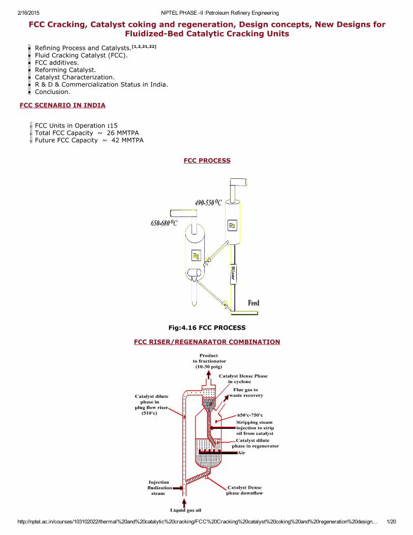
FCC PROCESS
Fig:4.16 FCC PROCESS
FCC RISER/REGENARATOR COMBINATION
2/16/2015 NPTEL PHASE II :Petroleum Refinery Engineering
http://nptel.ac.in/courses/103102022/thermal%20and%20catalytic%20cracking/FCC%20Cracking%20catalyst%20coking%20and%20regeneration%20design… 2/20
Fig:4.17 FCC/RISER/REGENARATOR COMBINATION
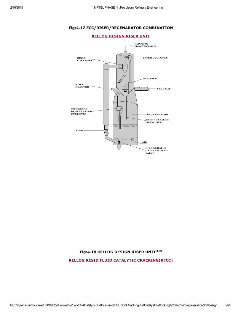
KELLOG DESIGN RISER UNIT
Fig:4.18 KELLOG DESIGN RISER UNIT[1,2]
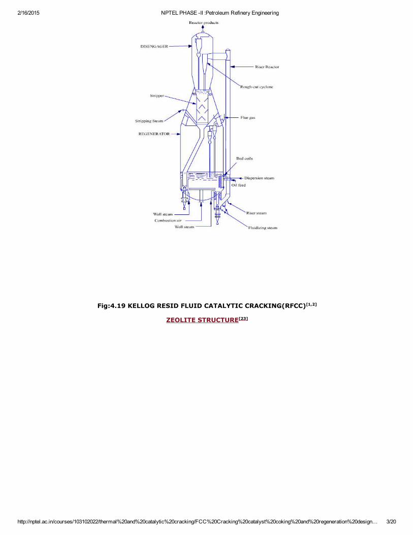
KELLOG RESID FLUID CATALYTIC CRACKING(RFCC)
2/16/2015 NPTEL PHASE II :Petroleum Refinery Engineering
http://nptel.ac.in/courses/103102022/thermal%20and%20catalytic%20cracking/FCC%20Cracking%20catalyst%20coking%20and%20regeneration%20design… 3/20
Fig:4.19 KELLOG RESID FLUID CATALYTIC CRACKING(RFCC)[1,2]
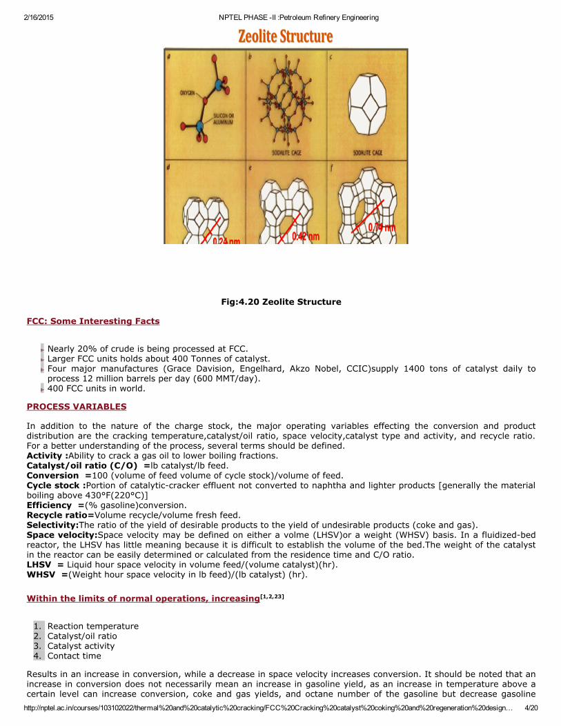
ZEOLITE STRUCTURE[23]
2/16/2015 NPTEL PHASE II :Petroleum Refinery Engineering
http://nptel.ac.in/courses/103102022/thermal%20and%20catalytic%20cracking/FCC%20Cracking%20catalyst%20coking%20and%20regeneration%20design… 4/20
Fig:4.20 Zeolite Structure
FCC: Some Interesting Facts
Nearly 20% of crude is being processed at FCC.Larger FCC units holds about 400 Tonnes of catalyst.Four major manufactures (Grace Davision, Engelhard, Akzo Nobel, CCIC)supply 1400 tons of catalyst daily toprocess 12 million barrels per day (600 MMT/day).400 FCC units in world.
PROCESS VARIABLES In addition to the nature of the charge stock, the major operating variables effecting the conversion and productdistribution are the cracking temperature,catalyst/oil ratio, space velocity,catalyst type and activity, and recycle ratio.For a better understanding of the process, several terms should be defined.Activity :Ability to crack a gas oil to lower boiling fractions.Catalyst/oil ratio (C/O) =lb catalyst/lb feed.Conversion =100 (volume of feed volume of cycle stock)/volume of feed.Cycle stock :Portion of catalyticcracker effluent not converted to naphtha and lighter products [generally the materialboiling above 430°F(220°C)]Efficiency =(% gasoline)conversion.Recycle ratio=Volume recycle/volume fresh feed.Selectivity:The ratio of the yield of desirable products to the yield of undesirable products (coke and gas).Space velocity:Space velocity may be defined on either a volme (LHSV)or a weight (WHSV) basis. In a fluidizedbedreactor, the LHSV has little meaning because it is difficult to establish the volume of the bed.The weight of the catalystin the reactor can be easily determined or calculated from the residence time and C/O ratio.LHSV = Liquid hour space velocity in volume feed/(volume catalyst)(hr).WHSV =(Weight hour space velocity in lb feed)/(lb catalyst) (hr). Within the limits of normal operations, increasing[1,2,23]
1. Reaction temperature2. Catalyst/oil ratio3. Catalyst activity4. Contact time
Results in an increase in conversion, while a decrease in space velocity increases conversion. It should be noted that anincrease in conversion does not necessarily mean an increase in gasoline yield, as an increase in temperature above acertain level can increase conversion, coke and gas yields, and octane number of the gasoline but decrease gasoline
2/16/2015 NPTEL PHASE II :Petroleum Refinery Engineering
http://nptel.ac.in/courses/103102022/thermal%20and%20catalytic%20cracking/FCC%20Cracking%20catalyst%20coking%20and%20regeneration%20design… 5/20
yield . In many FCC units, conversion and capacity are limited by the regenerator coke burning ability. This limitationcan be due to either air compression limitations or to the after burning temperatures in the last stage regeneratorcyclones. In either case FCC units are generally operated at the maximum practical regenerator temperature with thereactor temperature and throughput ratio selected to minimize the secondary cracking of gasoline to gas and coke. Withthe trend to heavier feedstocks, the carbon forming potential of catalytic cracker feeds is increasing, and some unitslimited in carbon burning ability because of limited blower capacity are adding oxygen to the air to the regenerator toovercome this limitation. Oxygen contents of the gases to the regenerator are being increased to 24–30% by volumeand are limited by regenerator temperature capability and heat removal capacity
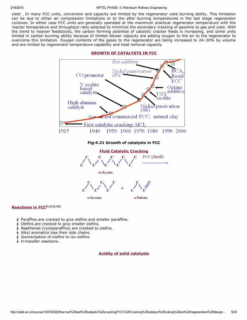
GROWTH OF CATALYSTS IN FCC
Fig:4.21 Growth of catalysts in FCC
Fluid Catalytic Cracking
Reactions in FCC[1,2,21,22]
Paraffins are cracked to give olefins and smaller paraffins.Olefins are cracked to give smaller olefins.Napthenes (cycloparaffins) are cracked to olefins.Alkyl aromatics lose their side chains.Isomerisation of olefins to isoolefins.Htransfer reactions.
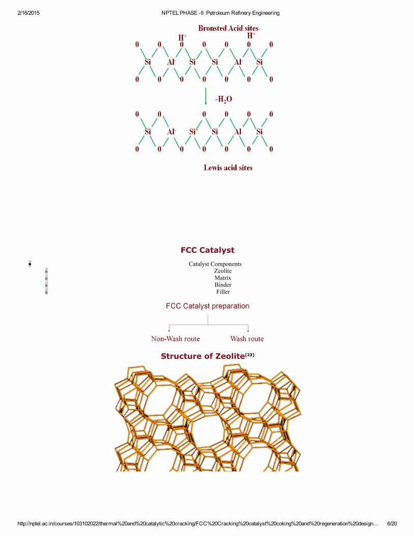
Acidity of solid catalysts
2/16/2015 NPTEL PHASE II :Petroleum Refinery Engineering
http://nptel.ac.in/courses/103102022/thermal%20and%20catalytic%20cracking/FCC%20Cracking%20catalyst%20coking%20and%20regeneration%20design… 6/20
FCC Catalyst
Catalyst ComponentsZeoliteMatrixBinderFiller
Structure of Zeolite[23]
2/16/2015 NPTEL PHASE II :Petroleum Refinery Engineering
http://nptel.ac.in/courses/103102022/thermal%20and%20catalytic%20cracking/FCC%20Cracking%20catalyst%20coking%20and%20regeneration%20design… 7/20
Fig:4.22 Structure of Zeolite
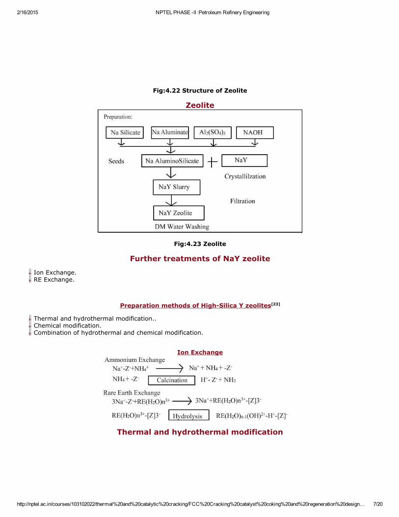
Zeolite
Fig:4.23 Zeolite
Further treatments of NaY zeolite
Ion Exchange.RE Exchange.
Preparation methods of HighSilica Y zeolites[23]
Thermal and hydrothermal modification..Chemical modification.Combination of hydrothermal and chemical modification.
Ion Exchange
Thermal and hydrothermal modification
2/16/2015 NPTEL PHASE II :Petroleum Refinery Engineering
http://nptel.ac.in/courses/103102022/thermal%20and%20catalytic%20cracking/FCC%20Cracking%20catalyst%20coking%20and%20regeneration%20design… 8/20
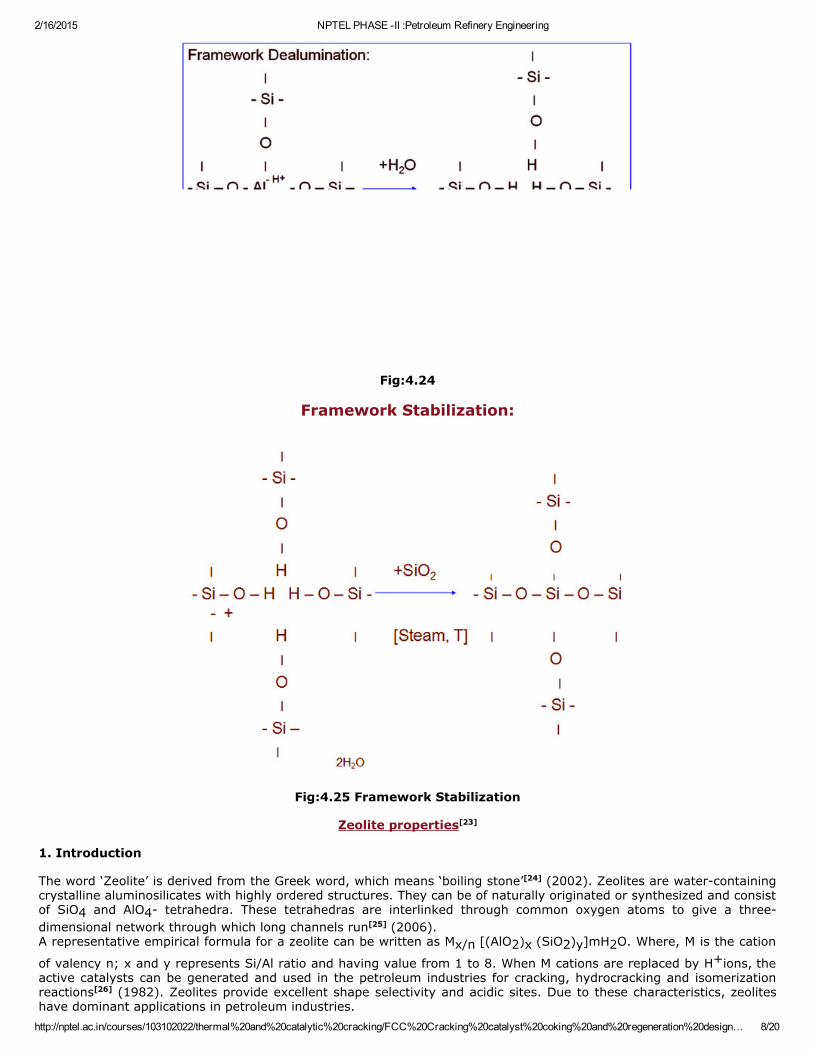
Fig:4.24
Framework Stabilization:
Fig:4.25 Framework Stabilization
Zeolite properties[23]
1. Introduction The word ‘Zeolite’ is derived from the Greek word, which means ‘boiling stone’[24] (2002). Zeolites are watercontainingcrystalline aluminosilicates with highly ordered structures. They can be of naturally originated or synthesized and consistof SiO4 and AlO4 tetrahedra. These tetrahedras are interlinked through common oxygen atoms to give a threedimensional network through which long channels run[25] (2006).A representative empirical formula for a zeolite can be written as Mx/n [(AlO2)x (SiO2)y]mH2O. Where, M is the cation
of valency n; x and y represents Si/Al ratio and having value from 1 to 8. When M cations are replaced by H+ions, theactive catalysts can be generated and used in the petroleum industries for cracking, hydrocracking and isomerizationreactions[26] (1982). Zeolites provide excellent shape selectivity and acidic sites. Due to these characteristics, zeoliteshave dominant applications in petroleum industries.
2/16/2015 NPTEL PHASE II :Petroleum Refinery Engineering
http://nptel.ac.in/courses/103102022/thermal%20and%20catalytic%20cracking/FCC%20Cracking%20catalyst%20coking%20and%20regeneration%20design… 9/20
Hydrocracking and hydroisomerization are the two of the most important processes of the petroleum refineries, whichare not possible without application of suitable catalysts (Fig.4.26). The continuous increase in global demand of thepetroleum products increases the valuation of these processes in modern refineries. Hydroisomerization is termed as theisomerization of nparaffins into branched isomers. Hydroisomerization of C4–C7 hydrocarbons has been applied for theproduction of gasoline with a high octane number. Hydroisomerization of C7 –C15 paraffins applies to improve dieselfuel cold flow properties, such as viscosity, pour point and freezing point. The hydroisomerization reaction is alwaysaccompanied by a hydrocracking reaction that lowers more or less the yield of that the isomerized feed molecules[27](2005).Catalysts used for hydroisomerization reactions are bifunctional in nature. They generally contain metal such as Pt, Pd,Ni etc. dispersed on acidic supports. While hydroisomerization and hydrocracking reactions, metals are responsible forhydrogenationdehydrogenation agent and acidic supports are responsible for isomerization and cracking of thesubstances[28] (2003). Zeolite acidity (number and strength distribution) and pore structure play important role inoverall reactions.Typical acidic supports of bifunctional catalysts used are amorphous oxides or mixture of oxides (i.e. HFtreated Al2O3,
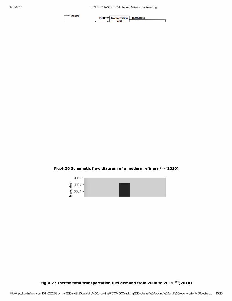
SiO2–Al2O3, ZrO2/SO42); zeolites (Y, Beta, Mordenite, ZSM5, ZSM22, ZSM12 etc.); silicoaluminophosphates(SAPO11, SAPO31, SAPO41) and mesoporous materials (MCM41, AlMCM41) (Deldari, 2005).Gasoline and diesel are the most important and valuable fractions generated by petroleum refineries. The demand ofthese two fractions have globally increased since last few years. The average demand for diesel will be almost twicethan that of the demand of gasoline in next few years (Fig.4.27). So, major part of the investments of the petroleumrefineries have covered processes for production or upgrading of middle distillate fractions to make them suitable fordiesel blendstock[29] (2010).
So, objective of this work is to develop suitable molecular sieve based catalysts for the hydroisomerization of middledistillate fractions. The catalyst should provide transition shape selectivity for branched isomers. Also, the catalystshould provide good mechanical strength during reaction conditions and structure (especially in the case of molecularsieves) should not collapse at reaction conditions. The zeolite molecular sieves successfully fulfilled all these criterionsand have been commercially used since their invention. Therefore, development of the noble metal (i.e. Pt, Pd etc.)loaded zeolite (i.e. ZSM12, ZSM22, ZSM48) supported catalysts, is the major objective. Also, development of kineticmodel for hydroisomerization followed by hydrocracking reactions will also be performed.
2/16/2015 NPTEL PHASE II :Petroleum Refinery Engineering
http://nptel.ac.in/courses/103102022/thermal%20and%20catalytic%20cracking/FCC%20Cracking%20catalyst%20coking%20and%20regeneration%20design… 10/20
Fig:4.26 Schematic flow diagram of a modern refinery [29](2010)
Fig:4.27 Incremental transportation fuel demand from 2008 to 2015[29](2010)
2/16/2015 NPTEL PHASE II :Petroleum Refinery Engineering
http://nptel.ac.in/courses/103102022/thermal%20and%20catalytic%20cracking/FCC%20Cracking%20catalyst%20coking%20and%20regeneration%20design… 11/20
2.1 Introduction to molecular sieves and zeolites (Szostak, 1989) In 1932, McBain proposed the term “Molecular Sieve” for the materials which have selective adsorption properties andthese materials separate components of a mixture on the basis of difference in molecular size and shape. The differentclasses of molecular sieves are listed in Fig.4.28 Structure of many of these materials are analogous, but all aredifferent in terms of elemental composition and aluminosilicates have been given the classical name ‘Zeolites’.Structurally zeolites are the crystalline aluminosilicates with a framework based on an extensive threedimensionalnetwork of oxygen ions. The AlO2 tetrahedra in the structure determine the framework charge and is balanced bycations, which occupy nonframework positions. The crystalline framework structure contains voids and channels ofdiscrete size. The pore opening ranges from 3 to 8Ao. The negative charge has been created by AlO2 tetrahedra and
balanced by cations like alkaline (Na+, K+, Rb+, Cs+), alkaline earth (Mg+2, Ca+2), NH4+, H3O+ (H+), TMA+
(Tetramethylammonium), other nitrogen containing organic cations, and rareearth and noble metal ions. Allaluminosilicates are molecular sieves but not zeolites. An aluminosilicate is called zeolite if it contains at least onealuminium ion per unit cell based on the bulk composition of the sample, with no allowance made for inhomogeneitieswithin the individual crystal on the microscopic level.
Fig:4.28 Classification of molecular sieve materials indicating the extensive variation in composition[30](1989)
Fig:4.29 Examples of pore opening in the zeolite molecular sieves[25] (2006) Zeolites have been classified on the basis of different structural elements. The kind of building unit most suitable for theclassification of the zeolites depends on the property under consideration. If we are able to identify ability of a perticularzeolite to selectively adsorb one component of a mixture over another, understanding of the detailed complex structureof that perticular zeolite would not be necessary. Size of the pore opening of the perticular zeolite is responsible forselective adsorption of perticular components. So, we can classify zeolite from on the basis of pore size to sequence ofbuilding blocks which form the regular network pattern characteristic of the zeolite. Each level acts as a model tounderstand, describe or visualize a specific aspect of a material.The first level of classification is based on pore size. All the zeolites used for catalytic or adsorption operations can be
2/16/2015 NPTEL PHASE II :Petroleum Refinery Engineering
http://nptel.ac.in/courses/103102022/thermal%20and%20catalytic%20cracking/FCC%20Cracking%20catalyst%20coking%20and%20regeneration%20design… 12/20
classified by the number of T atoms, where T is Si or Al that define pore opening. Till date only three types of poreopenings are known and of practical interest. They are 8member ring (small pore), 10member ring (medium pore)and 12member ring (large pore) zeolites (Fig.4.29). The distribution of products for different zeolites depends upondifference in their pore sizes. Example of 8member ring zeolites are Erionite, Chabazite and Type A. ZSM5, ZSM11,ZSM22, EU1 and Theta1 comes under the category of 10member ring zeolites. Whether Type Y, Mordenite(synthetic), ZSM12 and ß are the examples of 12member ring zeolites.Second level of classification is based on the number of dimensions encompassed by the pores and shape of the poremouth. There are one, two and threedimensional tubes or channels can be viewed in the zeolite structures. Analcite isthe example of onedimensional channels, while Mordenite has twodimensional intersectig channel system. ZSM5 andZSM11 contain intersecting threedimensional 10 ring channel system. The difference in shape and size of channelinteraction are responsible for subtle difference in selectivity between different zeolites. The size and shape of the poreopening can be determined by configuration of T and O atoms relative to each other, Si/Al ratio, size and location of thecation and temperature.Pore openings and channel systems determine catalytic and adsorptive properties of the zeolites. But, as also mentionedearlier they don’t provide any information on structural properties of the zeolites. Lack of information on structuralproperties of the zeolites led to develoment of Structural Building Units. The Structural Building Units can be classifiedinto Primary Building Units, Secondary Building Units, Extended Chain Building Units and Sheet Building Units. A primarybuilding unit is the individual tetrahedral TO4 unit, where T is either Si or Al. A secondary building unit (SBU) is thegeometric grouping of those tetrahedra. These SBU’s contain 4, 6, and 8member single rings; 44, 66, and 88member double rings; and 41, 51, and 441 branched rings. Most of the zeolites frameworks can be generated by thearrangement of different SBU’s. ZSM5 and Ferrierite can be described by their 51 building uits. Offretite, zeolite L,Cancrinite, and Erionite are generated using only single 6member rings. Some zeolite structures can be generated byvarious SBU’s. For example, the sodalite structure can be built from either the single 6member or the single 4memberring (Fig.4.30).
Fig:4.30 Generation of sodalite structure from either 6member rings or 4member rings[30] (1989). Arrangement of the secondary building units in space generates chain building units, which add further dimensions tosecondary building units. Various types of chains found in the zeolite structures is shown in Fig.4.31. Fig:4.31 Chains found in zeolite structures: (a) zigzag (b) sawtooth (c) double crankshaft (d) narsarsukite
(e) natrolite 4=1 and (f) pentasil chains [29](2010). Chain building units rearrange and form the sheet building units. Generally, chain building units are onedimensionaland sheet building units are twodimensional. In Fig.4.32 successive built up of the ZSM5 (MFI) is shown. Fig:4.32 The ZSM5 (MFI) structure can be built up successively: (a) the pentasil unit; (b) chains of pentasil
units; (c) layers of these chains; and (d) layers linked across inversion centres[29] (2010). 2.2 Hydrothermal synthesis of zeolites (Cundy[31] Cox, 2005) In late 1940s, Richard Barrer and Robert Milton have started synthesis of zeolites by conversion of known mineralphases under the action of strong salt solutions in the temperature range of 170 to 270oC. By 1953, Milton and hiscolleagues had synthesized 20 zeolites including 14 unknown as natural minerals. Initially the aim of study was tounderstand complex synthesis processes and later it has been shifted to discoveries of new materials, advances insynthesis techniques, innovations in theoretical modelling methods, development of new techniques for theinvestigations of reaction mechanisms and development of the new techniques for the characterization of the materials. A typical hydrothermal zeolite synthesis can be described in brief as follows:
Silica and alumina sources in the amorphous form have been mixed together in the alkaline pH and in an aqueousmedium with a cation source.The reaction mixture has been heated in a sealed autoclave at temperature above 100oC and autogeneouspressure.After reaching the appropriate temperature, reactants remain amorphous for some time and this time is known as“induction period”. Crystallization starts after this period of time.After appropriate time period, all the amorphous materials will be converted into zeolite crystals. These crystals arerecovered by filtration, washing and drying.
The Si and Al sources have been used in an oxide form and these amorphous precursors contain SiO and AlO bonds.At the end of the hydrothermal synthesis crystalline zeolite products containing SiOAl linkages has been created in thepresence of “mineralizing” agent (generally alkali metal hydroxide). The bond type of the product is very similar to thebond types of precursor oxides. So, it can be concluded that, no great enthalpy changes has been takes place. In fact,
2/16/2015 NPTEL PHASE II :Petroleum Refinery Engineering
http://nptel.ac.in/courses/103102022/thermal%20and%20catalytic%20cracking/FCC%20Cracking%20catalyst%20coking%20and%20regeneration%20design… 13/20
overall free energy change of the reaction is small enough to become the overall reaction kinetically controlled. Thisgives the benefit of generation of metastable products. To make the synthesis process industrially important, theproduct must contain reproducibility and the same specification each time. This needs to develop exact conditions forproduct optimization. This influences the choice of starting reagents from wide varieties of simple oxides or hydroxidesto sodium silicate solution and solid sodium aluminate. Usage of sodium silicate solution or solid sodium aluminate givesnot only benefits in terms of cost or ease of operation but also they offer optimum routes to particular materials.Flexibility in the choice of reagents enables equilibria to be approached from various directions. We may also get thekinetic benefits like preferred nucleation of one phase over another in the situations of possibility of cocrystallization ofthe materials.Now let’s come to the synthesis mechanism for zeolites. The most probable pathways can be given as induction period,nucleation and crystal growth in sequence. Induction period is the time (t) between the notional start of the reactionand the point at which the first crystal formation can be observed. According to the classical nucleation theory, theinduction period has been divided into three subunits as relaxation time (tr), time for formation of stable nucleus (tn)and time for the nucleus to grow to a detectable size (tg). ‘Nucleation’ is defined as the series of atomic or molecularprocesses by which the atoms or molecules of a reactant phase rearrange into a cluster of the product phase largeenough as to have the ability to grow irreversibly to a macroscopically larger size. The ‘cluster’ is defined as nucleus orcritical nuclei. The rate of nucleation (i.e., the number of nuclei formed per unit time per unit volume) can be expressedby an Arrheniustype equation[29] (2010): J = A exp (ΔG*/kT).................(1) Where, ΔG* is the critical Gibb’s free energy, k is rate constant at temperature T. Cations and organicstructuredirecting agents also involved in the nucleation process by surrounding themselves with metaloxide species in preferredgeometries. Crystal growth is considered as one of the most important step and studies tell that zeolite growthincreases linearly during most of the crystallization process for both gel and clear solution synthesis. Temperature, gelcomposition, agitation and aging are the various parameters which affect the zeolite growth[29] (2010). 2.3 Characterization of zeolites Characterization of the synthesized zeolites is very important aspect. A particular zeolite must contain good crystalstructure, required Si/Al ratio, desired BET surface area and pore size, desired acidic and metal sites, good dispersion ofmetal sites, proper crystal morphology etc. for particular application. Each of the above mentioned properties can beverified by various characterization techniques like XRay Diffraction (XRD), BET surface area analyzer, Solid stateNuclear Magnetic Resonance (Solid NMR), NH3 or Pyridine Temperature Programmed Reduction (NH3 TPD or PyridineTPD), H2 Chemisorption or COChemisorption, Scanning Electron Microscopy (SEM) and Transmission ElectronMicroscopy (TEM) (both normal and high resolution) etc. 2.4 Classification of zeolites Zeolites are comprehensively classified on the basis of their morphology, crystal structure, Chemical composition,effective pore diameter, origin of trivalent species donor. 2.4.1 Morphology Fibrous: Tetrahedra linked more numerous in one crystallographic .Lamellar (Open framework): Tetrahedral linkageswithin similar plane.Zeolites have been structurally classified on the basis of Secondary Building Unit (SBU). They can beexplained as cage, ring or cage like structures which forms the basic architecture of zeolites. Fig.4.33 shows some of theSBU.
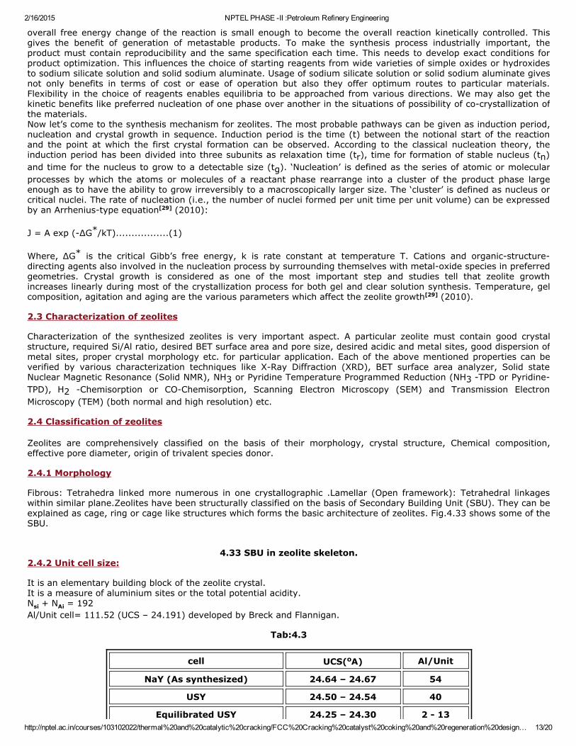
4.33 SBU in zeolite skeleton.2.4.2 Unit cell size: It is an elementary building block of the zeolite crystal.It is a measure of aluminium sites or the total potential acidity.Nsi + NAi = 192Al/Unit cell= 111.52 (UCS – 24.191) developed by Breck and Flannigan.
Tab:4.3
cell UCS(oA) Al/Unit
NaY (As synthesized) 24.64 – 24.67 54
USY 24.50 – 24.54 40
Equilibrated USY 24.25 – 24.30 2 13
2/16/2015 NPTEL PHASE II :Petroleum Refinery Engineering
http://nptel.ac.in/courses/103102022/thermal%20and%20catalytic%20cracking/FCC%20Cracking%20catalyst%20coking%20and%20regeneration%20design… 14/20
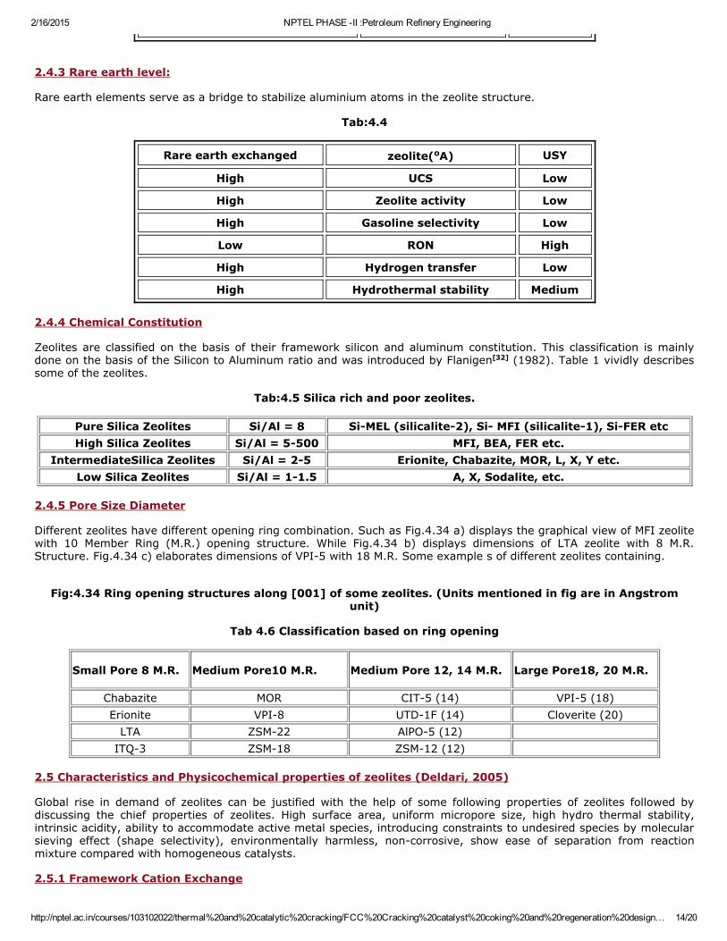
2.4.3 Rare earth level: Rare earth elements serve as a bridge to stabilize aluminium atoms in the zeolite structure.
Tab:4.4
Rare earth exchanged zeolite(oA) USY
High UCS Low
High Zeolite activity Low
High Gasoline selectivity Low
Low RON High
High Hydrogen transfer Low
High Hydrothermal stability Medium
2.4.4 Chemical Constitution Zeolites are classified on the basis of their framework silicon and aluminum constitution. This classification is mainlydone on the basis of the Silicon to Aluminum ratio and was introduced by Flanigen[32] (1982). Table 1 vividly describessome of the zeolites.
Tab:4.5 Silica rich and poor zeolites.
Pure Silica Zeolites Si/Al = 8 SiMEL (silicalite2), Si MFI (silicalite1), SiFER etcHigh Silica Zeolites Si/Al = 5500 MFI, BEA, FER etc.
IntermediateSilica Zeolites Si/Al = 25 Erionite, Chabazite, MOR, L, X, Y etc.Low Silica Zeolites Si/Al = 11.5 A, X, Sodalite, etc.
2.4.5 Pore Size Diameter Different zeolites have different opening ring combination. Such as Fig.4.34 a) displays the graphical view of MFI zeolitewith 10 Member Ring (M.R.) opening structure. While Fig.4.34 b) displays dimensions of LTA zeolite with 8 M.R.Structure. Fig.4.34 c) elaborates dimensions of VPI5 with 18 M.R. Some example s of different zeolites containing. Fig:4.34 Ring opening structures along [001] of some zeolites. (Units mentioned in fig are in Angstrom
unit)
Tab 4.6 Classification based on ring opening
Small Pore 8 M.R. Medium Pore10 M.R. Medium Pore 12, 14 M.R. Large Pore18, 20 M.R.
Chabazite MOR CIT5 (14) VPI5 (18)Erionite VPI8 UTD1F (14) Cloverite (20)LTA ZSM22 AlPO5 (12)
ITQ3 ZSM18 ZSM12 (12) 2.5 Characteristics and Physicochemical properties of zeolites (Deldari, 2005) Global rise in demand of zeolites can be justified with the help of some following properties of zeolites followed bydiscussing the chief properties of zeolites. High surface area, uniform micropore size, high hydro thermal stability,intrinsic acidity, ability to accommodate active metal species, introducing constraints to undesired species by molecularsieving effect (shape selectivity), environmentally harmless, noncorrosive, show ease of separation from reactionmixture compared with homogeneous catalysts. 2.5.1 Framework Cation Exchange
2/16/2015 NPTEL PHASE II :Petroleum Refinery Engineering
http://nptel.ac.in/courses/103102022/thermal%20and%20catalytic%20cracking/FCC%20Cracking%20catalyst%20coking%20and%20regeneration%20design… 15/20
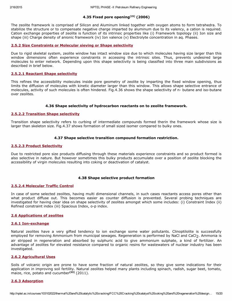
4.35 Fixed pore opening[25] (2006)
The zeolite framework is comprised of Silicon and Aluminum linked together with oxygen atoms to form tetrahedra. Tostabilize the structure or to compensate negative charge imparted by aluminum due to its valency, a cation is required.Cation exchange properties of zeolite is function of its intrinsic properties like (i) Framework topology (ii) Ion size andshape (iii) Charge density of anionic framework (iv) Ion valence (v) Electrolyte concentration in aq. Phases. 2.5.2 Size Constraints or Molecular sieving or Shape selectivity Due to rigid skeletal system, zeolite window has intact window size due to which molecules having size larger than thiswindow dimensions often experience constraints in accessing the intrinsic sites. Thus, prevents undesired largemolecules to enter network. Depending upon this shape selectivity is being classified into three main subdivisions asdescribed in brief below. 2.5.2.1 Reactant Shape selectivity This refines the accessibility molecules inside pore geometry of zeolite by imparting the fixed window opening, thuslimits the diffusion of molecules with kinetic diameter larger than this window. This allows shape selective entrance ofmolecules, activity of such molecules is often hindered. Fig.4.36 shows the shape selectivity of n butane and isobutaneover zeolites.
4.36 Shape selectivity of hydrocarbon reactants on to zeolite framework. 2.5.2.2 Transition Shape selectivity Transition shape selectivity refers to curbing of intermediate compounds formed therin the framework whose size islarger than skeleton size. Fig.4.37 shows formation of small sized isomer compared to bulky ones.
4.37 Shape selective transition compound formation restriction. 2.5.2.3 Product Selectivity Due to restricted pore size products diffusing through these materials experience constraints and so product formed isalso selective in nature. But however sometimes this bulky products accumulate over a position of zeolite blocking theaccessibility of virgin molecules resulting into coking or deactivation of catalyst.
4.38 Shape selective product formation 2.5.2.4 Molecular Traffic Control In case of some selected zeolites, having multi dimensional channels, in such cases reactants access pores other thanwhat product diffuse out. This becomes easier as counter diffusion is prevented. Several probing techniques areinvestigated for having clear idea on shape selectivity of zeolites amongst which some includes: (i) Constraint Index (ii)Refined constraint index (iii) Spacious Index, op index. 2.6 Applications of zeolites 2.6.1 Ionexchange Natural zeolites have a very gifted tendency to ion exchange some water pollutants. Clinoptilolite is successfullyemployed for removing Ammonium from municipal sewages. Regeneration is performed by NaCl and CaCl2. Ammonia isair stripped in regeneration and absorbed by sulphuric acid to give ammonium sulphate, a kind of fertilizer. Anadvantage of zeolites for elevated resistance compared to organic resins for wastewaters of nuclear industry has beeninvestigated. 2.6.2 Agricultural Uses Soils of volcanic origin are prone to have some fraction of natural zeolites, so they give some indications for theirapplication in improving soil fertility. Natural zeolites helped many plants including spinach, radish, sugar beet, tomato,maize, rice, potato and cucumber[33] (2011). 2.6.3 Adsorption
2/16/2015 NPTEL PHASE II :Petroleum Refinery Engineering
http://nptel.ac.in/courses/103102022/thermal%20and%20catalytic%20cracking/FCC%20Cracking%20catalyst%20coking%20and%20regeneration%20design… 16/20
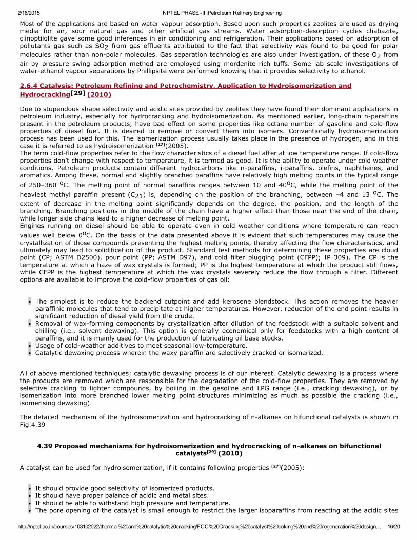
Most of the applications are based on water vapour adsorption. Based upon such properties zeolites are used as dryingmedia for air, sour natural gas and other artificial gas streams. Water adsorptiondesorption cycles chabazite,clinoptilolite gave some good inferences in air conditioning and refrigeration. Their applications based on adsorption ofpollutants gas such as SO2 from gas effluents attributed to the fact that selectivity was found to be good for polarmolecules rather than nonpolar molecules. Gas separation technologies are also under investigation, of these O2 fromair by pressure swing adsorption method are employed using mordenite rich tuffs. Some lab scale investigations ofwaterethanol vapour separations by Phillipsite were performed knowing that it provides selectivity to ethanol. 2.6.4 Catalysis: Petroleum Refining and Petrochemistry, Application to Hydroisomerization andHydrocracking[29] (2010) Due to stupendous shape selectivity and acidic sites provided by zeolites they have found their dominant applications inpetroleum industry, especially for hydrocracking and hydroisomerization. As mentioned earlier, longchain nparaffinspresent in the petroleum products, have bad effect on some properties like octane number of gasoline and coldflowproperties of diesel fuel. It is desired to remove or convert them into isomers. Conventionally hydroisomerizationprocess has been used for this. The isomerization process usually takes place in the presence of hydrogen, and in thiscase it is referred to as hydroisomerization [27](2005).The term coldflow properties refer to the flow characteristics of a diesel fuel after at low temperature range. If coldflowproperties don’t change with respect to temperature, it is termed as good. It is the ability to operate under cold weatherconditions. Petroleum products contain different hydrocarbons like nparaffins, iparaffins, olefins, naphthenes, andaromatics. Among these, normal and slightly branched paraffins have relatively high melting points in the typical rangeof 250–360 oC. The melting point of normal paraffins ranges between 10 and 40oC, while the melting point of theheaviest methyl paraffin present (C21) is, depending on the position of the branching, between –4 and 13 oC. Theextent of decrease in the melting point significantly depends on the degree, the position, and the length of thebranching. Branching positions in the middle of the chain have a higher effect than those near the end of the chain,while longer side chains lead to a higher decrease of melting point.Engines running on diesel should be able to operate even in cold weather conditions where temperature can reachvalues well below 0oC. On the basis of the data presented above it is evident that such temperatures may cause thecrystallization of those compounds presenting the highest melting points, thereby affecting the flow characteristics, andultimately may lead to solidification of the product. Standard test methods for determining these properties are cloudpoint (CP; ASTM D2500), pour point (PP; ASTM D97), and cold filter plugging point (CFPP); IP 309). The CP is thetemperature at which a haze of wax crystals is formed; PP is the highest temperature at which the product still flows,while CFPP is the highest temperature at which the wax crystals severely reduce the flow through a filter. Differentoptions are available to improve the coldflow properties of gas oil:
The simplest is to reduce the backend cutpoint and add kerosene blendstock. This action removes the heavierparaffinic molecules that tend to precipitate at higher temperatures. However, reduction of the end point results insignificant reduction of diesel yield from the crude.Removal of waxforming components by crystallization after dilution of the feedstock with a suitable solvent andchilling (i.e., solvent dewaxing). This option is generally economical only for feedstocks with a high content ofparaffins, and it is mainly used for the production of lubricating oil base stocks.Usage of coldweather additives to meet seasonal lowtemperature.Catalytic dewaxing process wherein the waxy paraffin are selectively cracked or isomerized.
All of above mentioned techniques; catalytic dewaxing process is of our interest. Catalytic dewaxing is a process wherethe products are removed which are responsible for the degradation of the coldflow properties. They are removed byselective cracking to lighter compounds, by boiling in the gasoline and LPG range (i.e., cracking dewaxing), or byisomerization into more branched lower melting point structures minimizing as much as possible the cracking (i.e.,isomerising dewaxing). The detailed mechanism of the hydroisomerization and hydrocracking of nalkanes on bifunctional catalysts is shown inFig.4.39
4.39 Proposed mechanisms for hydroisomerization and hydrocracking of nalkanes on bifunctionalcatalysts[29] (2010)
A catalyst can be used for hydroisomerization, if it contains following properties [27](2005):
It should provide good selectivity of isomerized products.It should have proper balance of acidic and metal sites.It should be able to withstand high pressure and temperature.The pore opening of the catalyst is small enough to restrict the larger isoparaffins from reacting at the acidic sites
2/16/2015 NPTEL PHASE II :Petroleum Refinery Engineering
http://nptel.ac.in/courses/103102022/thermal%20and%20catalytic%20cracking/FCC%20Cracking%20catalyst%20coking%20and%20regeneration%20design… 17/20
inside the pore.
2.6.5 Matrix
Physical functions
BinderDiffusivityDiluting mediumSodium sinkHeat transfer
Manufacturing
4.40 Main Reactions in FCC Catalysis
FCC Catalyst
4.41 FCC Catalyst
ROLE OF ADDITIVES
4.42 Role of Additives
FCC Additives
4.43 FCC Additives
ZSM5 additive
Octane boosting.Increase in C3 and C4 olefins and LPG maximization.Preference for higher butylene yield.Initially ZSM5 cracks paraffins and olefins. As cycle time increases, olefin isomerisation dominates while gasoline
2/16/2015 NPTEL PHASE II :Petroleum Refinery Engineering
http://nptel.ac.in/courses/103102022/thermal%20and%20catalytic%20cracking/FCC%20Cracking%20catalyst%20coking%20and%20regeneration%20design… 18/20
loss and octane improvement is minimum.
Fig 4.44 A typical flow sheet for higher molecular hydrocarbons (feed) cracking with ZSM5 towardspropylene and butylenes.
How to Maximize Propylene Yield?
Fig 4.45 A typical flow sheet for higher molecular hydrocarbons (feed) cracking with ZSM5 towards lighter
olefins, napthenes, paraffins and aromatics.Cracking by ZSM5 favored by:[23]
Low pressureHigh TempreatureFast diffussion of primary cracking product from the catalyst.
Secondary catalyst reactions
Hitransfer.isomerization,cyclization favored by:High host catalyst ZMHigh zeolite acid strengh,high UCS.Slow diffusion of primary cracking product from the catalyst.
Suppressing competitions from secondary reaction is the major key for maximizing propylene.
Hydrogen Transfer Index
The relative activity of the host FCC catalyst for secondary reactions can be quantified using the Hydrogen TransferIndex (HTI):
Designing a Max C3= Catalyst for Resid[23] REQUIREMENTS:
Minimize Hydrogen Transfer to increase C3= plateau.Vanadium tolerance for good hydrothermal stability.Good bottoms cracking ability.Low coke selectivity.High accessibility reduces HTI. Primary cracking products can diffuse from the catalyst faster and are less likely toundergo secondary reactions.
Balance between HTI and Activity
Low Hydrogen Transfer maximizes propylene.If achieved by reducing Rare Earth, activity is lower.There is a limit to how much zeolite can be used in catalyst to compensate for activity loss.Dilution effects from large amounts of ZSM5 must also be overcome.The challenge, particularly for Resid, is achieving high propylene yield AND good conversion with acceptablecatalyst addition rate.
Vanadium
At regenerator conditions, Vanadium on equilibrium catalyst exists as V+5.In the regenerator ‘V’ presented on the catalyst converted Vanadium pentoxide (V2O5).Under regenerator conditions V2O5 is mobile because it melts at regenerator conditions.In the presence of steam V2O5 is converted to Vanadic acid H3VO4.
Ni passivators
‘Ni’ passivating agents are antimony, bismuth and rare earth compounds (Ce, La, etc…).Antimony: This is a first commercially used additive.NiSb alloys formed.1. Antimony will block ‘Ni’ active sites.2. Alternation of electronic and chemisorption properties.3. The amount of antimony available to passivate nickel will be determined by the equilibrium between antimony
2/16/2015 NPTEL PHASE II :Petroleum Refinery Engineering
http://nptel.ac.in/courses/103102022/thermal%20and%20catalytic%20cracking/FCC%20Cracking%20catalyst%20coking%20and%20regeneration%20design… 19/20
and nickel.
Draw back:Antimony effects on CO combustion promoters. Vanadium Passivators[1,2,23]
Vanadium passivating agents are Tin, Titanium, Zirconium and rare earth compounds.Other than the above stated passivating agents there are other passivating agents are also reported. They aregermanium, gallium, indium, tellurium, aluminium, barium, zinc, boron, phosphorous, tungsten, tantalum, lithiumand cadmium.
Metal traps
Metal traps are added to the FCC Catalyst as separate particle or incorporated directly into the catalyst particle.These metal traps react with incoming metals like nickel and vanadium and form an inert compounds.
Fig 4.46 A typical FCC flow sheet in petroleum refining system which incorporates an FCC to distill high
octane gasoline and LPG from the heavy contents of the crude oil with sulphur
Catalyst/Additives for Sulphur Control
GraceGSR Technology for sulphur reduction 1525%Sulphur reduction is achieved mainly from front end .For Gasoline.
AKZOResolve FCC catalyst selective matrix activity
1530% Sulphur reduction.Optimized access.For Gasoline.
BCA Additive2030% achieved pesovskite /Spinel.Alumina Matrix.Sulphur capture by Matrix.
References
1. Rao, B.K.B.(1990). Modern Petroleum Refining Processes (2nd Edition Ed.) Oxford & IBH Publishers. ISBN 8120404815.
2. James H. Gary and Glenn E. Handwerk (2001). Petroleum Refining: Technology and Economics (4th ed.). CRCPress. ISBN 0824704827.
3. Mohanty, P., Pant, K.K., Parikh, J., Sharma, D.K. (2011) Fuel Process. Technol. 92, 600 608.4. Mohanty, P., Pant, K.K., Naik, S. N., Das, L. M., and Vasudevan, P. (2011) ‘Fuel production from biomass: Indian
perspective for pyrolysis oil, Journal of Scientific & Industrial Research 70,668674.5. James. G. Speight (2006). The Chemistry and Technology of Petroleum (4th ed.). CRC Press. ISBN 0849390672.6. Patel, M., Pant,K. K., Mohanty, P. (2011) Renewable hydrogen generation by steam reforming of acetic acid over
CuZnNi supported calcium aluminate catalysts. Nanocatalysis for Fuels and Chemicals 9, 111137.7. Mohanty, P., Patel, M., Pant, K. K. (2012) Sustainable hydrogen from steam reforming of acetic acid as a model
oxygenate over CuZn supported calcium aluminate catalyst. Bioresources Technology 123, 558565.8. Zaidi H.A and Pant K.K. (2004) Catalytic conversion of Methanol to Gasoline range hydrocarbons, Catalysis Today,
96, 155160.9. Reza Sadeghbeigi (2000). Fluid Catalytic Cracking Handbook (2nd ed.). Gulf Publishing. ISBN 0884152898.10. Kister, Henry Z. (1992). Distillation Design (1st Edition ed.). McGrawHill. ISBN 0070349096.11. Karl Kolmetz, Andrew W. Sloley et al. (2004), Designing Distillation Columns for Vacuum Service, 11th India Oil
and Gas Symposium and International Exhibition, September 2004, Mumbai, India (also published in HydrocarbonProcessing, May 2005).
12. Leffler, W.L. (1985). Petroleum refining for the nontechnical person (2nd Edition ed.). PennWell Books. ISBN 0878142800.
13. Editors: Jacqueline I. Kroschwitz and Arza Seidel (2004). KirkOthmer Encyclopedia of Chemical Technology (5thed.). Hoboken, NJ: WileyInterscience. ISBN 0471488100.
14. McCabe, W., Smith, J. and Harriott, P. (2004). Unit Operations of Chemical Engineering (7th ed.). McGraw Hill.
2/16/2015 NPTEL PHASE II :Petroleum Refinery Engineering
http://nptel.ac.in/courses/103102022/thermal%20and%20catalytic%20cracking/FCC%20Cracking%20catalyst%20coking%20and%20regeneration%20design… 20/20
ISBN 0072848235.15. Kister, Henry Z. (1992). Distillation Design (1st ed.). McGrawHill. ISBN 0070349096.16. King, C.J. (1980). Separation Processes (2nd ed.). McGraw Hill. ISBN 0070346127.17. Perry, Robert H. and Green, Don W. (1984). Perry's Chemical Engineers' Handbook (6th ed.). McGrawHill. ISBN 0
070494797.18. Felder, R., Roussea, W. (2005). Elementary Principles of Chemical Processes (3rd ed.). Wiley. ISBN 9780471
687573.19. Beychok, Milton (May 1951). "Algebraic Solution of McCabeThiele Diagram". Chemical Engineering Progress.20. Seader, J. D., and Henley, Ernest J. (1998). Separation Process Principles. New York: Wiley. ISBN 0471586269.21. http://www.refinerycatalysts.pro/pdfs/BASF_Rare_Earth_Tech_Note_USL_sfs.pdf.22. http://petrofed.winwinhosting.net/upload/1619March11/Day2/3_V%20Srikanth.pdf.23. http://www.izaonline.org/natural/default.htm24. Schuring, D. Diffusion in zeolites: towards a microscopic understanding. Ph.D. Thesis submitted to Eindhoven
University of Technology, The Netherlands, 2002.25. Hagen, J. Industrial catalysis a practical approach. WILEYVCH Verlag GmbH & Co. KGaA: Weinheim, 2006.26. Rees, L. V. C. When zeolite is not a zeolite? Nature 1982, 296, 491492.27. Deldari, H. Suitable catalysts for hydroisomerization of longchain normal paraffins. App. Cat., A: Gen. 2005, 293,
110.28. Gopal, S.; Smirniotis, P. G. Pt/HZSM12 as a catalyst for the hydroisomerization of C5–C7 nalkanes and
simultaneous saturation of benzene. App. Cat., A: Gen. 2003, 247, 113123.29. Cejka, G.; Corma, A.; Zones, S. Zeolites and Catalysis Synthesis, Reactions and Applications. WILEYVCH Verlag
GmbH & Co. KGaA: Weinheim, 2010.30. Szostak, R. Molecular Sieves: Principles of Synthesis and Identification. Thomson Science, Division of International
Thomson Publishing: UK, 1989.31. Cundy, C. C.; Cox, P. A. The hydrothermal synthesis of zeolites: Precursors, intermediates and reaction
mechanism. Micropor. Mesopor. Mater. 2005, 82, 178.32. Wilson, S. T.; Lok, B. M.; Messina, C. A; Cannan, T. R.; Flanigen, E. M. Aluminophosphate Molecular Sieves: A New
Class of Microporous Crystalline Inorganic Solids. J. Am. Chem. Soc. 1982, 104, 11461147.33. Ramesh, K.; Reddy, D. D. Zeolites and their potential uses in agriculture. Adv. Agron. 2011, 113, 219241.