flute liner technology in fractured rock an … liner technology in fractured rock –an evolution...
TRANSCRIPT

FLUTe Liner Technology in Fractured Rock – An Evolution in Groundwater
Characterization
Mark HigginsEast Coast Field ManagerWarminster, PA 18974

Objectives of the FLUTe Approach:
• Seal an open borehole
• Map transmissive features in location and flow capacity
• Map relative distribution of contaminants
• Long term monitoring of water quality and head distribution at many discrete depths per hole

Why seal an open borehole?
• Example location with contamination source intersecting the uppermost fracture.
• Lower fractures containing clean water are naturally isolated from contaminated fracture.
SWL
DNAPL
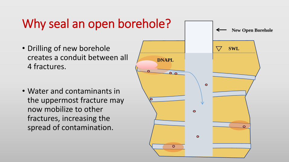
Why seal an open borehole?
• Drilling of new borehole creates a conduit between all 4 fractures.
• Water and contaminants in the uppermost fracture may now mobilize to other fractures, increasing the spread of contamination.
SWL
DNAPL
New Open Borehole

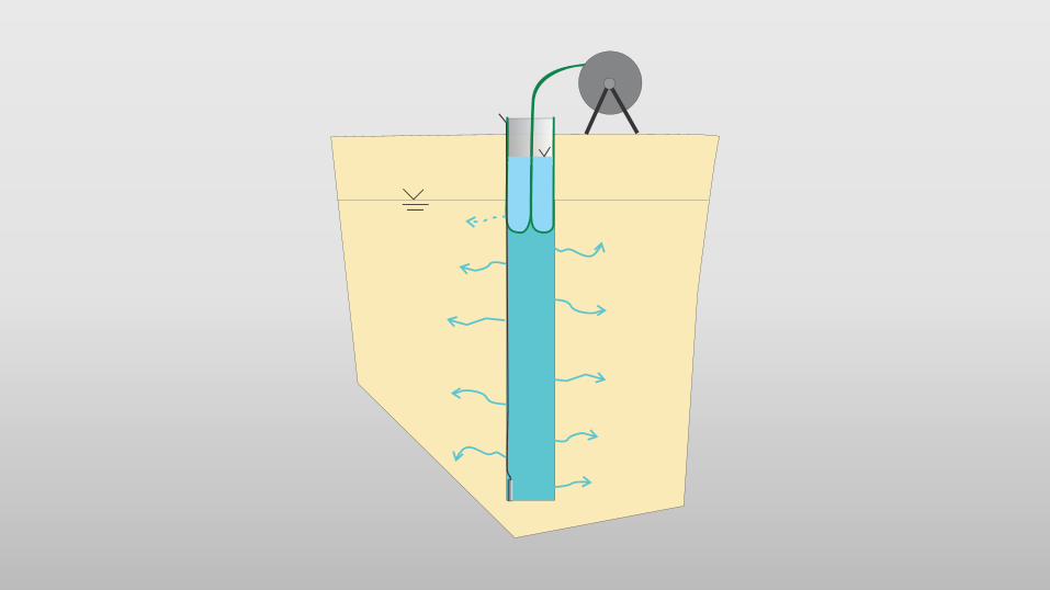
The blank liner installation to seal the borehole
Water hose
Liner on reel(inside out)
Original waterin hole pushed into formation,
or removed bypumping
SWL
Water level in liner
liner


Note the stepwise inversionprocedure for removal


The seal quality is exceptional
• 6 inch diam. Hole
• Liner conforms to variations in the borehole, large and small
• Seam tape in liner lower left is 1” wide

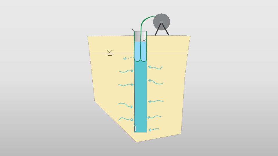
The blank liner can be utilized as a carrier for a NAPL/FACT FLUTe• The NAPL FLUTe cover wicks
NAPL upon contact, changes colors, and allows for visible confirmation of any pure product in the hole.
• The FLUTe Activated Carbon (FACT) strip absorbs contaminants from the matrix and fracture flows. When analyzed it provides a continuous replica of the contaminant distribution with depth.

The NAPL FLUTe maps NAPL at the hole wallAbsorbs NAPL upon contact producing a bright stain for 2-D map
Coal Tar Rye NY
TCE Denver CO Xylene UK
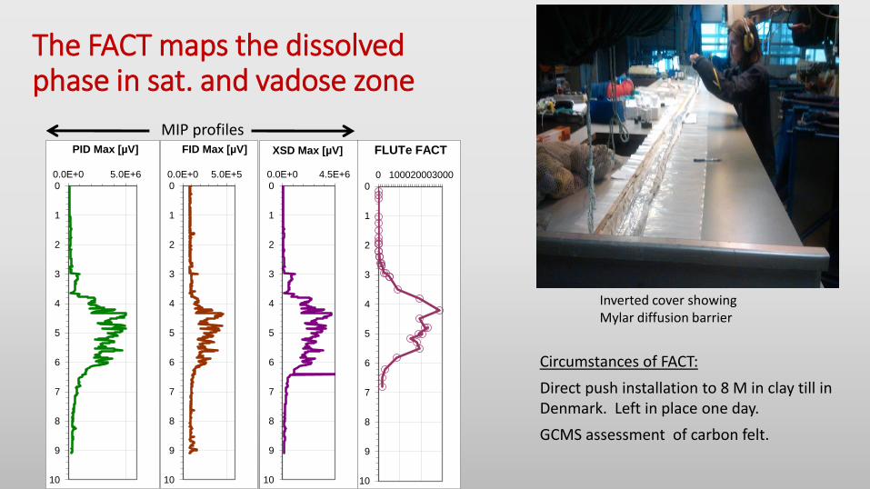
The FACT maps the dissolved phase in sat. and vadose zone
0
1
2
3
4
5
6
7
8
9
10
0.0E+0 5.0E+6
PID Max [µV]
0
1
2
3
4
5
6
7
8
9
10
0.0E+0 5.0E+5
FID Max [µV]
0
1
2
3
4
5
6
7
8
9
10
0.0E+0 4.5E+6
XSD Max [µV]
0
1
2
3
4
5
6
7
8
9
10
0 100020003000
FLUTe FACT
Inverted cover showingMylar diffusion barrier
Circumstances of FACT:
Direct push installation to 8 M in clay till in Denmark. Left in place one day.
GCMS assessment of carbon felt.
MIP profiles

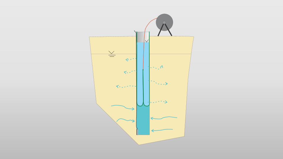
The FLUTe transmissivity profile is fast and high resolution
• Performed with the same blank liner used for sealing the borehole

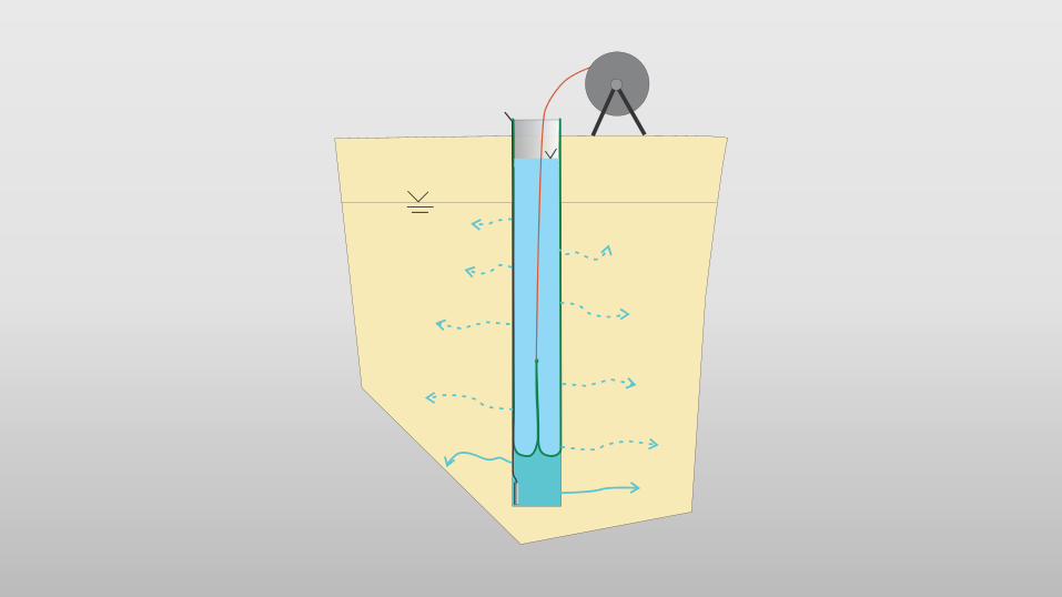
How a profiler works
Water Addition
hose Liner on reel
(inside out)
Original waterin hole pushed
into formation
VelocityMeter
HL
transducer
Liner head
measurement
surface
conductor

The Water FLUTe systemin place
“Sample tube”
“Pump tube” ½” id
Secondcheck valve
First check valve
Sealing liner
Spacerdefiningmonitoring interval
Formationhead in pump
Port to pumptube
Port behindspacer throughliner
Pump quick connectTransducer
cable
Recordingpressure transducer (optional)
ACT transducer (optional)


21 Port Water FLUTe with Transducers

Purging 12 Ports Simultaneously

Experience with FLUTe systems
• Water FLUTe and other FLUTe systems have been in use for over 20 years.
• Installations have been done in boreholes from 2 to 18 inches diameter to depths greater than 1000 ft.
• Many hundreds of systems are in place from Canada to Puerto Rico and as far as Denmark and Germany.
• Customers include: Boeing, Shell, GE, Exxon Mobil, EPA, NASA, US Army Corps, Lockheed among many other notable agencies and contractors.
• FLUTe Systems and components are sourced, manufactured, constructed, and made in the USA
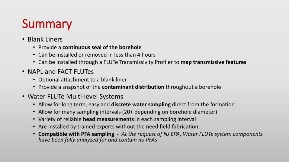
Summary• Blank Liners
• Provide a continuous seal of the borehole• Can be installed or removed in less than 4 hours• Can be installed through a FLUTe Transmissivity Profiler to map transmissive features
• NAPL and FACT FLUTes• Optional attachment to a blank liner• Provide a snapshot of the contaminant distribution throughout a borehole
• Water FLUTe Multi-level Systems• Allow for long term, easy and discrete water sampling direct from the formation• Allow for many sampling intervals (20+ depending on borehole diameter)• Variety of reliable head measurements in each sampling interval• Are installed by trained experts without the need field fabrication.• Compatible with PFA sampling - At the request of NJ EPA, Water FLUTe system components
have been fully analyzed for and contain no PFAs

Data Collected Using These Methods

Some Other FLUTe Methods to Ask About
• Shallow Water FLUTe – Less expensive, smaller tubing, utilizes peristaltic pumping, compatible with transducers for head monitoring
• PFAST System – Efficient, cost effective, PFA multi-level sampling system
• Geoprobe installations – Variety of small diameter systems that can be installed quickly and easily via geoprobe rods
• Reverse Head Profile – performed in conjunction with T Profile using a blank liner to measure the head distribution in a borehole
• Angled and horizontal sampling systems– air or water driven, previously utilized under landfills, buildings, mountain sides, and other difficult to access locations.
• Vadose Sampling Systems
• And many other innovative applications that can be tailored to your needs

Thank You
•Questions?

Check frequently asked questions on website for each method.• Need more information, www.flut.com, or call 505-852-0128
• Need to discuss feasibility? Call 505-930-1154
• Need to know about installations or scheduling? [email protected], or call 505-883-4032
• Need a quote, [email protected]
• Need a procedure, [email protected], [email protected]
• Feel free to contact me about any of the above items as well, [email protected] or call 215-394-5760
We frequently deal with artesian conditions, karst, low flow formations, fractured rock and sediments, shallow and deep, small and large diameter. We don’t like squeezing clays or unstable boreholes, but we have methods even for those.