flux 2dinteractive design of electrical machines and systems
TRANSCRIPT
FLUX 2DINTERACTIVE DESIGN OF ELECTRICAL
MACHINES AND SYSTEMS
P. Girard, P. Wendling, B. Morel, J .C. Sabonnadiere
To cite this version:
P. Girard, P. Wendling, B. Morel, J .C. Sabonnadiere. FLUX 2DINTERACTIVE DESIGN OFELECTRICAL MACHINES AND SYSTEMS. Journal de Physique Colloques, 1984, 45 (C1),pp.C1-861-C1-865. <10.1051/jphyscol:19841175>. <jpa-00223650>
HAL Id: jpa-00223650
https://hal.archives-ouvertes.fr/jpa-00223650
Submitted on 1 Jan 1984
HAL is a multi-disciplinary open accessarchive for the deposit and dissemination of sci-entific research documents, whether they are pub-lished or not. The documents may come fromteaching and research institutions in France orabroad, or from public or private research centers.
L’archive ouverte pluridisciplinaire HAL, estdestinee au depot et a la diffusion de documentsscientifiques de niveau recherche, publies ou non,emanant des etablissements d’enseignement et derecherche francais ou etrangers, des laboratoirespublics ou prives.
JOURNAL DE PHYSIQUE Colloque CI, supplCment au no I, Tome 45, janvier 1984 page C1-861
FLUX 2D INTERACTIVE DESIGN OF ELECTRICAL MACHINES AND SYSTEMS
P. Girard, P. Wendling, B. ~orel*and J .C. Sabonnadilre'
CEDRAT, Chemin du pre' carre', ZIRST Meyzan, 38240 MeyZan, France ' ~ n s t i t u t National PoZytechnique de GrenobZe, E. N.S. I.E.G., B.P. N o 46, 38042 Saint-Martin-drHe'res, France
RESUME
La construction du matdriel dlectrique ndcessite une bonne connaissance de la rGpartition du flux, L'association des mdthodes de calcul de champ et des tech- niques de C.A.O. conduit & des systlmes interactifs tels que FLUX, bas6 sur la msthode des dl6ments finis. Par construction graphique, l'utilisateur d5finit la ggomdtrie et rdalise le dscoupage en dl6ments finis. Le post-processeur lui permet de d6terminer des paramltres importants tels que forces, couples, induction.. . L'utilisation d'un systsme de C.A.O. tel que FLUX assure une production de qualit6 avec un important gain de temps.
ABSTRACT
The design of electromagnetic systems must take into account the spatial distri- bution-of magnetic flux density. The conjuction of field computation and C.A.D. t echniques lead to in te rac t ivecomputer aided design systems like FLUX, based on the finite elements method. By graphic display, the designer check his data and prepare the finitt elements mesh. The post-processor allows him to get the values of important parameters like forces, torques, fields... The use of C.A.D. systems like FLUX insure a good quality of product and the saving of a large amount of design time.
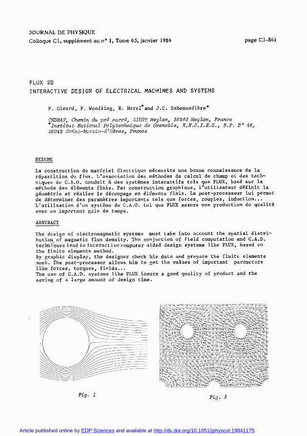
Fig. I Fig. 3
Article published online by EDP Sciences and available at http://dx.doi.org/10.1051/jphyscol:19841175

JOURNAL DE PHYSIQUE
1. INTRODUCTION
Scientific methods and means of calculation are of course used both in the design of electric circuits and in the analysis of the electromagnetic, thermal and mechanical aspects. However, although the mechanical and thermal calculations use well known methods developed by specialists, the electromagnetic analysis has, until recently, used calculating methods whose basic hypothesis do not suffi- ciently integrate the complexity of shapes and the non-linearity of materials. It has only been during the last ten years that developments in numerical methods have made possible a precise determination of the two key values in electro- magnetic design : the field and the magnetic flux density.
In the design of a magnet, the electromagnetic performances of the device are always more or less complex functions of the magnetic (forces, torques, elec- tromotive forces) or field and flux density.
It is therefore essential, for the design of such electric equipment to have at one's disposal a means of c lculating the electromagnetic field. This is why the research was carried out CJ , [ 2 ] to adapt the finite element methods to solve Maxwell equations for complex structures made of materials whose effects are non- linear (saturation, anisotropy). After having verified the reliability of the results obtained, the methods and techniques of computer aided design were applied to develop a software package which provides the engineer with an interactive description of his material, a simple, controlled manipulation of calculus algorithms and the utilization of the results by an electrical engineer.
The conjuction of numerical methods and C.A.D. techniquesleadusto a software package which serves to help the design of two-dimensionnal or axysymetric problems by the calculation of the fields and which we have called FLUX 2D.
2. THE FLUX 2D PACKAGE
FLUX 2D has been designed and built whith the underlying principle that he engineer must be able, at all times, to control the progress of his work using his experience and knowledge of the physics of the device which he is designing.
The following paragraph shows, with the help of an example the characteristics of each of the subsystems of FLUX 2D [3] .
3. DESCRIPTION OF FLUX 2D
A) The sub-system ENTREE
The geometry of the magnetic system is entered section by section, building up the whole picture step by step. In fact the device is decomposed into its components, each of them being called an assembly, and each assemby having a specific characteristic. Each assembly is made up of elementary entities called meshes, which are rectilinear or curvelinear, quadrilateral or triangular shapes. The name of a material can eventually be alloted to each mesh or assembly. The lines of each mesh may be segments or arcs of circles or parabolas which them- selves are defined by the most elementary entities, the points. The designer types the points coordinates , then little by little builds up the lines, the meshes and the assemblies, the final objective being to obtain the device as a specific assembly.
The designer can, at all times, check the correctness of the structure of the data which represents the machine being designed, either by graphic display of the each part of the geometric figure already built or by directly scannning the structure assemblies or meshes. It is of course possible at all times to modify any element of the structure.

The time taken to define a device can vary from a few minutes for a simple device to about an hour for a complex structure. Systems which geometry is repetitive through the common geometric transforms (translation, rotation, symmetry. .. ) are generated by defining the images of the original pattern and building up an assembly by regroupingthe pattern and its images. This use of the images for building the assembly is very important during the finite element cutting out when the designer will only be concerned with the original pattern, while the system will assure the same cutting out for all the images. The cut- ting out is performed in an interactive graphic way in which the designer is helped by the software. The system presents to designer each of the initial meshes successively. He canthenchoose to cut each mesh in one of several possible ways.
When the cutting out of the original meshes is finished the system itself assures this cutting out for the whole of the device. It is the possible to display this cutting out to be sure of the quality.
B) Definition of the physical properties
When describing the device during "ENTREE" the designer allots a name to the materials for each assembly or mesh. These names, which represent physical properties, are transfered during the cutting out to finite elements which make up each zone.
The characteristics of the problem being thus established, the subsystem PROPHY will then successively propose each of the ?ones which the designer has defined in "~~T~EE",showing the reference of a material alloted to each zone. The designer may have assigned the real name of a material which exists in the data bank of materials. We can also give the name of an existing material or using the keyboard to enter the B (H) curve and then display it on the screen to ensure that it fulfils the monotoniy conditions necessary for the calcu- lations. When the characteristics of the material are simple numerical values the designer is required to supply this value using the specified units. After that, a plot of the boundary conditions at these nodes.
C) Solution of the equations : RESO 2D
The computation processor which works on the solution of the system of non-linear equations, resulting from the preceding processors, works using the data struc- ture concerned by the problem as it has been defined by the designer.
D) The post-processor
Three types of results can be obtained from the final processors : isovalues, pointwise values and global quantities. It is possible, from the calculation of potential or the potential vector, to obtain a map of the field consisting of the equipotentials or field lines. In the same way, in time dependant problems a calculation of ancillary values such as the current density or the density of power dissipated can be plotted as isovalues.
The second kind of results which it is possible to display on the screen are the pointwise values of certain quantities (potentials, fields current densities) which confirm for the designer the validiy of the design. This is carried out in an interactive way, the choice of points being made either by their coordinates or on the screen with the cross-hair.
Finally, the designer has the possibility of having the global electrical or mechanic values calculated such as the forces, torques, energy and other values which make possible the calculation of other parameters (inductances, e.m.f, ... ) which enable him to estimate the overall quality of his design.

Cl-864 JOURNAL DE PHYSIQUE
4 . THE INDUSTRIAL USE OF FLUX 2D
FLUX 2D has been available since the spring of 1981 on the CII-HB 68 computer of the Centre Interuniversitaire de Calcul de GRENOBLE. It has been commercialized through the TRANSPAC Network system by CEDRAT under licence from the C.N.R.S.
The simplest means of using FLUX 2D is through TRANSPAC using a terminal inst- alled in the clients own offices. If the client does not wish to invest in a terminal, CEDRAT can provide a terminal situated in GRENOBLE. For those firms which do not wish to provide the manpower time necessary to learn and use the software,CEDRAT can provide an engineering service whereby they can sub-contract the work and be provided directly with the results.
5. ACCURACY
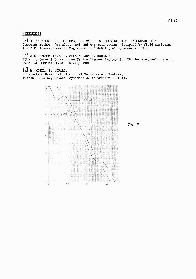
As it is known in finite elements analysis the error method depends on the size of elements and the round off an other computation errors depends on their size. Generally mathematical theorems gives error which are too large to fit Indus- trial or scientific design requirements. But the actual error for correct dis- cretization schema is often much less than the upper bound given by these theorems. In order to give an illustration of these remarks we have made on a typical problem (flow around a cylindrical hole) an error analysis by comparison with an analytical formula. The figure ( 1 ) shows the potential lines obtain around one hole. For this problem we have calculated the values of potential along a segment parallel to the Y axe and beginning at the boundary of the hole. This calculation has been realized with two differents discretizations ; one with 4 5 elements the other with 500 elements. The comparison beetween these values and these obtained by the analytical calculation are reported on the figure (2) where we can see that the error decreases quickly when Y increases and this more regulary for the finest discretization. The figures (3) presents such a discretization for a problem with 5 holes. We have experienced on this example that by a very careful analysis, formulation and discretization it is possible to obtain for the fields good accuracy. This experience will enlarge the field of application of e.m.f. to electromagnetic problems.
6. CONCLUSION
Throughout this paper we have tried to show the design of electrical devices necessary calls for the calculation of electromagnetic fields.
This fact reads to the research of programmes which make possible an accurate determination of the electromagnetic fields in ~ometrical~ycomplex structures made of materials whose physical properties are often non-linear. These finite element programmes which solves systems of many hundreds if not thousands of nonlinear equations now have a response time sufficiently short for an interactive use to be possible.
However, the spreading of their use in industry has been held back by the problems posed by the handling of such large quantities of geometrical and physical data both at the input and output. These use of general C.A.D. techniques has enabled us to create the FLUX 2D package which facilitates the interactive graphic repre- sentation of the electric entities (fields, forces, torques ... ) adapted ta the designing of an electric device.It therefore offers to designers a scientific means of designing elctromecEanica1 devices which is practical to use. Moreover it appears at the view of the experiments on accuracy that is need for application in fundamental physics.
REFERENCES
[!I B. ANCELLE, J.L. COULOMB, Ph. MASSE, G. MEUNIER, J.C. SABONNADIERE : Computer methods for electrical and magnetic devices designed by field analysis. I.E.E.E. Transactions on Magnetics, vol MAG 15, no 6, November 1979.
[2) J. C SABONNADIERE, G. MEUNIER and B. MOREL : FLUX : a General Interactive Finite Element Package for 2D Electromagnetic Field, Proc. of COMPUMAG Conf. Chicago 1981.
[_?I M. MOREL, P. GIRARD, : Interactive Design of Electrical Machines and Systems, PCI/MOTOCORN'82, GENEVA September 27 to October 1 , 1982.
Fig. 2