flux pinning in general adrian crisan school of metallurgy and materials, university of birmingham,...
TRANSCRIPT

Flux pinning in general
Adrian CrisanSchool of Metallurgy and Materials, University of Birmingham, UK
and
National Institute of Materials Physics, Bucharest, Romania


CONTENTS
• Introduction: type I vs. type II
• Vortices
• Pinning
• Bulk Pinning Force Density
• Pinning Potential

INTRODUCTION: Type I vs. Type IIType I superconductors
- They cannot be penetrated by magnetic flux lines (complete Meissner effect)- They have only a single critical field at which the material ceases to superconduct, becoming resistive- They are usually elementary metals, such as aluminium, mercury, lead

Type II superconductors
- Gradual transition from superconducting to normalwith an increasing magnetic field- Typically they superconductat higher temperatures and fieldsthan Type I- Between Meissner and normal state there is a large “mixed” or “vortex” state- They have two critical fields (upper and lower)- They are ussually metal alloys,intermetallic compounds, complex oxides (e.g., Cu-based HTSC)and, recently discovered, pnictides and chalcogenides
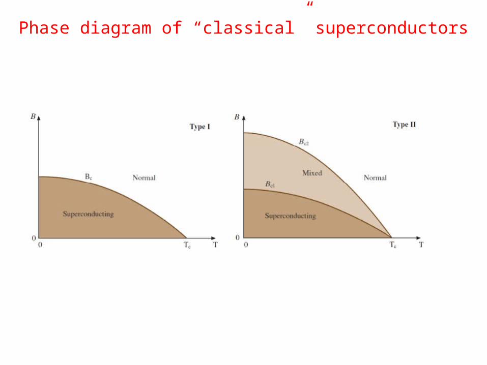
Phase diagram of “classical” superconductors

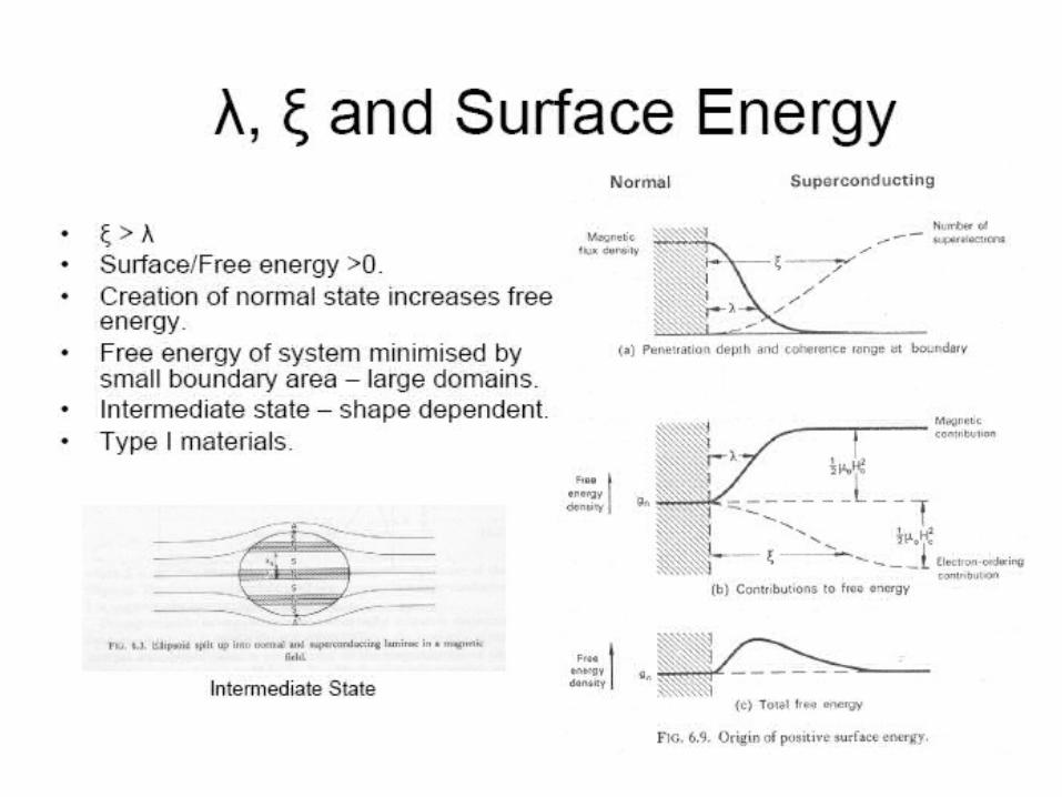
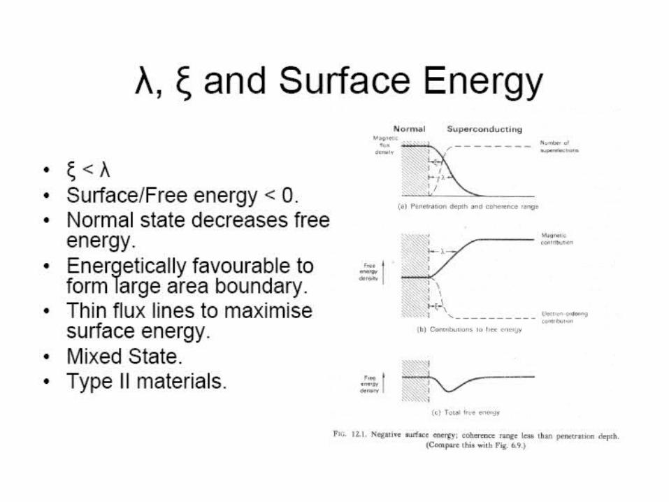
Penetration depth (l)
- Diamagnetic material(no internal flux)- Currents to repel external fluxconfined to surface- Surface currents must flow in finite thickness (penetration depth l)

Coherence length (x)- characterises the distance over which the superconducting wave
function y(r) can vary without undue energy increase - the distance over which the superconducting carriers
concentration decreases by Euler’s number e- GL parameter k=l/ ; x if <1/2k 1/2 then Type I; >1/2k 1/2 then
Type II

II. VORTICESVortex (mixed) state- Normal regions thread through superconductor- Ratio between surface andvolume of the normal phaseis maximised- Cylinders of normal material parallel to the applied field (normal cores)- Cores arranged in regular patternto minimize repulsion between cores(close-packed hexagonal lattice) – flux lattice


Flux quanta - vortex

Phase diagram of High-Tc superconductors and Vortex Melting Lines
The vortex lattice undergoes a first-order melting transition transforming the vortex solid into a vortex liquid [Fisher et al, PRB 43,130, 1991]. For high anisotropy, at low magnetic fields (approx 1 Oe in BSCCO [A.C. et al, SuST 24, 115001, 2011), there is a reentrance of the melting line [Blatter et al, PRB 54, 72, 1996].The flux lines in the vortex -liquid are entangled resulting in an ohmic longitudinal response, hence the vortex liquid and normal metallic phases are separated by a crossover at Hc2.
For low enough currents-VL- linear dissipation: E ≈ J-VS (VGlass)- strongly nonlinear dissipation: E ≈ exp[-(JT/J)m]

III. PINNINGLorenz force (FL) and pinning force (Fp)In the presence of a magnetic field perpendicular to the current
direction, a Lorentz force FL = j ×f0, where j is the current and f0 is the magnetic flux quantum, acts on the vortices
• If FL is smaller than the pinning force Fp, vortices do not move.
Defect-free sample Point defects Columnar defects

Dimensionality and strength of PCs

IV. BULK PINNING FORCE DENSITY
• FP determined from magnetization loops M(Ha)
Fp=BxJc
Jc=Ct.DM.
)3
1(
4
2
b
abda
mJ c
(thin films; m=DM/2; d-thickness; a,b-rectangle dim.)

Dew-Hughes model
F = Fp/Fpmax = hp(1-hq) ; h = B/Birr
p and q depend on the types of pinning centres.- Classified by the number of dimensions that are large
compared with the inter-flux-line spacing; and- by the type of the core: “Dk pinning” and “normal pinning”
Ususlly there are several types of pinning centres.F = Ahp1(1-hq1)+Bhp2(1-hq2)+Chp3(1-hq3)+.......
D. Dew-Hughes, Philosophical Magazine 30 (1974) 293

Geometry
of pin
Type of
centre
Pinning
function
p, q Position of
maximum
Max.
Const.
Volume Normal A(1-h)2 p=0; q=2 - A=1
Δκ Bh(1-h) p=1; q=1 h=0.5 B=4
Surface Normal Ch1/2(1-h)2 p=1/2; q=2 h=0.2 C=3.5
Δκ Dh3/2(1-h) p=3/2; q=1 h=0.6 D=5.37
Point Normal Eh(1-h)2 p=1; q=2 h=0.33 E=6.76
Δκ Fh2(1-h) p=2; q=1 h=0.67 F=6.76

0
0.2
0.4
0.6
0.8
1.0
0.2 0.4 0.6 0.8
Volume normal; (1-h)2, no max; F=1
0
0.05
0.10
0.15
0.20
0.25
0.2 0.4 0.6 0.8
Volume Dk; h(1-h) , max at 0.5, Fm=0.25, A=4
0
0.1
0.2
0.3
0.2 0.4 0.6 0.8
Surface n; h1/2(1-h)2 ; max at 0.2, Fm=0.286, B= 3.5
0
0.05
0.10
0.15
0.20
0.2 0.4 0.6 0.8
Surface Dk; h3/2(1-h) ; max at 0.6, Fmax=0.186, C=5.37

0
0.05
0.10
0.15
0.2 0.4 0.6 0.8
Point n; h(1-h)2; max at 0.33, Fmax=0.148, D=6.76
0
0.05
0.10
0.15
0.2 0.4 0.6 0.8
Point Dk; h2(1-h) ; max at 0.67, Fmax=0.148; E=6.76

V. PINNING POTENTIAL• Energy needed by the flux line to escape from
the potential well crated by the pinning centre• Shape and influence on superconducting
properties modelled in several ways, depending on material, strength and distribution of pinning centres
• In 1962 Anderson predicted that movement of vortices with a drift velocity v will create dissipation (electric field) E=Bxv

Dissipation occurs through two mechanisms:
• 1. Dipolar currents which surround each moving flux line (eddy currents) and which have to pass through “normal conducting vortex core”
• 2. Retarded relaxation of the order parameter when vortex core moves
• Anderson and Kim predicted that thermal depinning of flux lines can occur at finite temperatures T (“flux creep”).
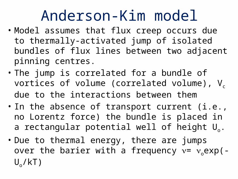
Anderson-Kim model• Model assumes that flux creep occurs due to
thermally-activated jump of isolated bundles of flux lines between two adjacent pinning centres.
• The jump is correlated for a bundle of vortices of volume (correlated volume), Vc due to the interactions between them
• In the absence of transport current (i.e., no Lorentz force) the bundle is placed in a rectangular potential well of height Uo.
• Due to thermal energy, there are jumps over the barier with a frequency = oexp(-Uo/kT)

(1)
(1)
(3)
(2)
(2)
(3)
(1): I=0(2): 0<I<Io
(3): I=Io
)(
)/1(
)/1(
/
0
00
00
0000
00
00
kT
U
kT
U
b
f
kt
BJvxU
kT
BJvxU
bf
bf
ee
JJUU
JJU
JvxJBJUBJvxUU
ee
Second term is ussualy neglected, since current densities of interest are smaller than J0
Critical current density is defined arbitrarily at a certain electric field, e.g., 10-6 V/cm. It follows:
)ln(ln
)1(ln
0
0
0
0
)/1(
0
00
tJ
J
J
kT
U
e
c
c
kT
JJU c

Logarithmic decay, magnetic relaxationJ; M (a.u.)
ln (t)
K-A model: -pinning potential decreases linearly with current-remnant magnetization and persistent current (or critical current density) decay logarithmically with time

Modified Anderson-Kim model
• Tilted-washboard cosine potential, which leads to U=U0[1-(J/Jc)]3/2
• The two forms can be generalized as U=U0[1-(J/Jc)]
• Such forms focus on the detailed behavior near Jc, which is appropriate for the classic superconductors where fluctuation effects cause only slight degradation of Jc

Larkin-Ovchinnikov collective pinning model• Cooperative aspects of vortex dynamics• Formation of vortex lattice will be a result of a
competition between: -vortex-vortex interaction, which tends to place
a vortex on a lattice point of a periodic hexagonal/triangular lattice; and
- vortex-pin interaction, which tends to place a vortex on the local minimum of the pinning potential
• v-v interaction promotes global translational invariant order
• v-p interaction tend to suppress such long-range order, if pinning potential varies randomly

• Long-range order of an Abrikosov lattice is destroyed by a random pinning potential, no matter how weak it is.
• Periodic arrangement is preserved only in a small corellated volume vc which depends on the strength of the pinning potential and the elasticity of the vortex lines
• Correlated volume vc increase strongly with decreasing current density J, which leads to a power-law dependence of effective pinning potential on the current density

1;)( 0
J
JUJU c
The above dependence leads to a non-ohmic current-voltage characteristic of the form:
J
J
kT
UV c0exp
In an inductive circuit, V is proportional to dJ/dt
)/1ln()/(1)( 00 ttUkTJtJ c T010-6 s
/1
0
0
/1
00
lnln)(
U
kTJ
t
t
U
kTJtJ cc

Zeldov effective pinning• Magneto-resistivity and I-V curves of YBCO films• Potential well having a cone-like structure
exhibiting a cusp at its minimum and a broad logarithmic decay with the distance
J
JUU eff
*
0 ln
E. Zeldov et al, PRL 62, (1989) 3093 , PRL . 56, (1990) 680A.C. et al, SuST 22, 045014, 2009
kT
UV effexp
kT
U
kT
U
J
JCt
J
JCt
J
J
kT
UCtV
00***
0 .lnexp.lnexp.