fm 55-450-2 army helicopter internal load … - army helicopter internal... · fm 55-450-2 army...
TRANSCRIPT

FM 55-450-2 Table of Contents
*FM 55-450-2
Field ManualNO 55-450-2
HEADQUARTERSDEPARTMENT OF THE ARMYWashington, DC, 5 June 1992
FM 55-450-2
ARMY HELICOPTER INTERNAL LOAD
OPERATIONS
Table of Contents
PREFACE
CHAPTER 1 - INTERNAL CARGO-CARRYING HELICOPTERS
CHAPTER 2 - PLANNING OPERATIONS
CHAPTER 3 - TIE-DOWN EQUIPMENT
CHAPTER 4 - HELICOPTER INTERNAL CARGO-HANDLING SYSTEM (HICHS)
CHAPTER 5 - MISCELLANEOUS LOADING PROCEDURES
http://www.globalsecurity.org/military/library/policy/army/fm/55-450-2/index.html (1 of 2)25/02/2005 12:38:02 PM

FM 55-450-2 Table of Contents
CHAPTER 6 - LOAD PREPARATION, LOADING, AND TIE-DOWN INSTRUCTIONS
APPENDIX - NATIONAL STOCK NUMBERS FOR TIE-DOWN DEVICES AND SPARE PARTS
GLOSSARY
REFERENCES
AUTHORIZATION LETTER
DISTRIBUTION RESTRICTION: Approved for public release; distribution is unlimited.
*This publication supersedes FM 55-450-2, 24 August 1984.
http://www.globalsecurity.org/military/library/policy/army/fm/55-450-2/index.html (2 of 2)25/02/2005 12:38:02 PM

FM 55-450-2 Chptr 1 Internal Cargo-Carrying Helicopters
CHAPTER 1
INTERNAL CARGO-CARRYING HELICOPTERS
1-1. INTRODUCTION. This chapter identifies the Army helicopters used for carrying internal loads. It also describes the capacities, capabilities, and limitations of these helicopters.
1-2. UTILITY HELICOPTERS. A utility helicopter is a general-purpose aircraft that has limited carrying capability. Its mission includes transporting troops, cargo, or patients. Two helicopters fall into this type: the Iroquois and the Blackhawk.
a. The UH-1 (Iroquois) is a single-turbine-engine, single-rotor helicopter with a skid-type landing gear (Figure 1-1). There are three models of the UH-1: H, M, and V. The differences among models are engine horsepower, rotor size, and cargo compartment size and configurations.
(1) The UH-1 is used for aerial fire support, aerial command posts, light tactical transport, medical evacuation, and electronic surveillance.
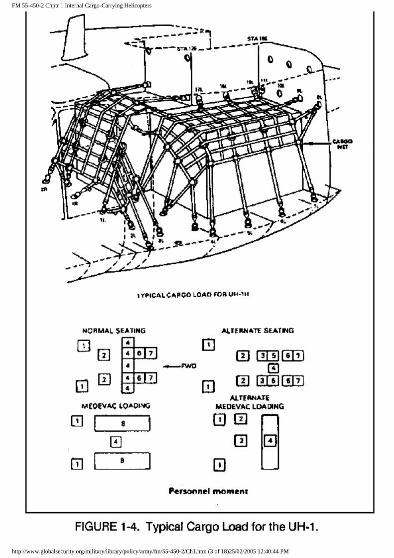
(2) Depending on the model, the UH-1 can seat up to 11 combat-equipped troops. The cargo compartment floor has a maximum load limit of 100 psf. The cargo area contains about 220 cubic feet of obstruction-free cargo load space.
(3) The tie-down rings in the floor have a rated capacity of 1,250 pounds in the vertical and 500 pounds in the horizontal direction. Figure 1-2 shows the tie-down rings, and Figure 1-3 shows the UH-1 cargo compartment dimensions. Figure 1-4 shows a typical cargo load for the UH-1.
http://www.globalsecurity.org/military/library/policy/army/fm/55-450-2/Ch1.htm (1 of 18)25/02/2005 12:40:44 PM

FM 55-450-2 Chptr 1 Internal Cargo-Carrying Helicopters
http://www.globalsecurity.org/military/library/policy/army/fm/55-450-2/Ch1.htm (2 of 18)25/02/2005 12:40:44 PM
FM 55-450-2 Chptr 1 Internal Cargo-Carrying Helicopters
http://www.globalsecurity.org/military/library/policy/army/fm/55-450-2/Ch1.htm (3 of 18)25/02/2005 12:40:44 PM

FM 55-450-2 Chptr 1 Internal Cargo-Carrying Helicopters
(4) The loading crew assembles the cargo and baggage to be transported. At the time of assembly and before loading, the loading crew compiles data covering weight, dimensions, center of gravity (CG) location, and contact areas for each item.
(5) Heavier packages will be loaded first and placed in the aft section against the bulkhead for CG range purposes.
(6) Calculate the allowable load and loading distribution by determining the final CG location, staying within the allowable limits for safe operating conditions.
(7) When operating the helicopter at critical gross weights, use the exact weight of each occupant plus equipment. If weighing facilities are not available, or if the tactical situation dictates otherwise, compute loads as follows:
● Combat-equipped soldiers: 300 pounds per individual. ● Combat-equipped paratroopers: 350 pounds per individual. ● Crew and passengers with no equipment: compute weight according to each
individual's estimate. ● Litter patients (including litter, splints, and so forth): 200 pounds per
individual. ● Medical attendants: 200 pounds per individual.
b. The UH-60 (Blackhawk) is a twin-turbine-engine, single-rotor helicopter with a tricycle-type landing gear (Figure 1-5). It has a four-blade main rotor system. The Army uses two models. The UH-60A has an 8,000-pound load capacity and the UH-60L has a 9,000-pound load capacity.
(1) The UH-60 is used mainly for tactical transport of troops, supplies, and equipment. It is also used for training, mobilization, medical evacuation (Figure 1-6), and development of new and improved concepts.
http://www.globalsecurity.org/military/library/policy/army/fm/55-450-2/Ch1.htm (4 of 18)25/02/2005 12:40:44 PM

FM 55-450-2 Chptr 1 Internal Cargo-Carrying Helicopters
(2) Depending on how the seats are installed, the cargo compartment of the UH-60 can seat up to 14 combat-equipped troops (Figure 1-7). The cargo compartment floor has a maximum load limit of 300 psf. The cargo compartment dimensions are about 72 inches wide, 54-inches high, and 150 inches long (Figures 1-8 and 1-9).
http://www.globalsecurity.org/military/library/policy/army/fm/55-450-2/Ch1.htm (5 of 18)25/02/2005 12:40:44 PM

FM 55-450-2 Chptr 1 Internal Cargo-Carrying Helicopters
http://www.globalsecurity.org/military/library/policy/army/fm/55-450-2/Ch1.htm (6 of 18)25/02/2005 12:40:44 PM

FM 55-450-2 Chptr 1 Internal Cargo-Carrying Helicopters
http://www.globalsecurity.org/military/library/policy/army/fm/55-450-2/Ch1.htm (7 of 18)25/02/2005 12:40:44 PM

FM 55-450-2 Chptr 1 Internal Cargo-Carrying Helicopters
(3) The tie-down rings in the floor have a rated capacity of 5,000 pounds in any direction. The cargo restraint net rings on the walls and ceiling have a rated capacity of 3,500 pounds (Figure 1-10).
http://www.globalsecurity.org/military/library/policy/army/fm/55-450-2/Ch1.htm (8 of 18)25/02/2005 12:40:44 PM

FM 55-450-2 Chptr 1 Internal Cargo-Carrying Helicopters
(4) When operating the helicopter at critical gross weights, use the exact weight of each occupant plus equipment. If weighing facilities are not available, or if the tactical situation dictates otherwise, compute loads as follows:
● Combat-equipped soldiers: 300 pounds per individual. ● Combat-equipped paratroopers: 350 pounds per individual. ● Crew and passengers with no equipment: compute weight according to each
individual's estimate.
1-3. CARGO HELICOPTERS. The cargo helicopter has a much larger capacity for carrying loads than the utility helicopter. The cargo helicopter can lift heavy, oversize loads, such as artillery weapons and ammunition, vehicles, and large boxes. The two types of cargo helicopters are the Chinook and the Tarhe.
a. The CH-47 (Chinook) aircraft is a twin-turbine-engine, tandem-rotor helicopter (Figure 1-11). There are presently two models (C and D) in the inventory. They differ mainly in engine horsepower, rotor blades, and gross weight capacity.
(1) The CH-47 is used for troop movement, cargo and weapons transportation, and as an air ambulance under day, night, visual, and instrument conditions.
(2) The CH-47 has a power-up operated ramp that permits straight-in rear loading. Two auxiliary loading ramps are hinged to the aft end ramp. When the ramp is lowered, these auxiliary ramps provide flush contact between the ramp and the ground. They may be positioned to accommodate various vehicle tread widths or butted together for easier loading of bulk cargo. The fuselage design gives the helicopter a water-landing capability. A gas turbine, auxiliary power unit provides hydraulic and electric power for ground operations.
(3) The Chinook is fitted with a hydraulic winch for use in cargo loading and rescue operations. A 3,000-pound capacity winch is mounted on the floor in the right-hand forward bulkhead. The winch has 150 feet of cable and can winch up to 12,000 pounds of cargo with the aid of snatch blocks. In addition, an internal cargo-handling system with rollers can be installed in the CH-47D model cargo
http://www.globalsecurity.org/military/library/policy/army/fm/55-450-2/Ch1.htm (9 of 18)25/02/2005 12:40:44 PM

FM 55-450-2 Chptr 1 Internal Cargo-Carrying Helicopters
compartment.
(4) The cargo compartment floor rests on rubber vibration isolators. The floor has a maximum load limit of 300 psf. The treadway aft of station 160 will withstand a wheel load of 2,500 pounds. The remaining treadway area will withstand a wheel load of 1,000 pounds. When used for additional cargo space, the ramp must be positioned level with the cargo floor, and the load on the ramp must not exceed 3,000 pounds. All models have the same cargo compartment dimensions: 90 inches wide, 78 inches high, and 366 inches long (Figure 1-12). The forward door is 36 inches wide and 66 inches high. The ramp opening is 90 inches wide and 78 inches high, and ramp incline is 6.7 degrees.
http://www.globalsecurity.org/military/library/policy/army/fm/55-450-2/Ch1.htm (10 of 18)25/02/2005 12:40:44 PM

FM 55-450-2 Chptr 1 Internal Cargo-Carrying Helicopters
(5) The eighty-three 5,000-pound capacity tie-down fitting in the cargo floor are equally spaced in five rows 20 inches apart longitudinally (Figure 1-13). The four in the ramp are in a rectangular pattern. Each 5,000-pound capacity fitting swivels freely and can resist a single maximum load of 5,000 pounds exerted along any radius of a hemisphere, the flat side of which is the surface of the floor. The fittings are hinged so that they can be seated in floor recesses when not in use.
http://www.globalsecurity.org/military/library/policy/army/fm/55-450-2/Ch1.htm (11 of 18)25/02/2005 12:40:44 PM

FM 55-450-2 Chptr 1 Internal Cargo-Carrying Helicopters
(6) Eight 10,000-pound capacity tie-down fittings are on the cargo compartment floor. Four fittings are interposed along both outboard rows of 5,000-pound capacity fittings, spaced at intervals of 80 inches from station 240 to station 480. These fittings are installed only when necessary because they are not always used and they might be in the way. When they are to be used, the fittings are screwed into threaded receptacles at the fitting locations. When they are not being used, threaded plugs are screwed into the receptacles to prevent entrance of foreign material and to protect the thread in the receptacles.
CAUTION
The 10,000-pound capacity tie-down fittings must be screwed into the threaded receptacles to full depth to achieve their rated capacity.
(7) The ramp provides a means of quickly loading and unloading troops and cargo. It can also support portions of a cargo load that exceed the longitudinal dimensions of the cargo floor. When used for additional cargo space, the ramp must be positioned so that the ramp floor is level with the cargo floor. The weight of the cargo item resting on the ramp must not exceed 3,000 pounds or 300 psf.
(8) The cargo compartment can hold up to 33 combat-equipped troops, 24 litters, or a combination of both (Figure 1-14). When operating the helicopter at a critical gross weights, use the exact weight of each occupant plus equipment. If weighing facilities are not available, or if the tactical situation dictates otherwise, compute loads as follows:
● Combat-equipped soliders: 300 pounds per individual. ● Combat-equipped paratroopers: 350 pounds per individual. ● Litter patient (including litter, splints, and so forth): 200 pounds per
individual. ● Medical attendants: 200 pounds per individual. ● Crew and passengers with no equipment: compute weight according to each
individual's estimate.
http://www.globalsecurity.org/military/library/policy/army/fm/55-450-2/Ch1.htm (12 of 18)25/02/2005 12:40:44 PM

FM 55-450-2 Chptr 1 Internal Cargo-Carrying Helicopters
b. The CH-54 (Tarhe) is a twin-turbine-engine, single-rotor helicopter (Figure 1-15). Two models of CH-54 are used by the military: A and B. They differ mainly in their lifting capability. The B model has more engine power and has a detachable pod that gives it internal load capabilities.
http://www.globalsecurity.org/military/library/policy/army/fm/55-450-2/Ch1.htm (13 of 18)25/02/2005 12:40:44 PM

FM 55-450-2 Chptr 1 Internal Cargo-Carrying Helicopters
(1) The CH-54 is used to transport troops, equipment, and weapons under day, night, visual, and instrument conditions.
(2) The detachable universal pod that allows internal loads is used for many operations (Figures 1-16 and 1-17). It holds up to 45 combat-equipped troops or 24 litters (Figure 1-18). When the litters are installed, there is still room for 15 seats down the middle for ambulatory patients, attendants, or troops. The pod has a reinforced tread area that will hold equipment as heavy as a 12,700-pound howitzer. The pod has no winch, so the load must be driven or pushed into the pod. The pod can be loaded on the ground and then raised up to the helicopter. Wheels on the pod allow it to be moved on the ground.
http://www.globalsecurity.org/military/library/policy/army/fm/55-450-2/Ch1.htm (14 of 18)25/02/2005 12:40:44 PM

FM 55-450-2 Chptr 1 Internal Cargo-Carrying Helicopters
http://www.globalsecurity.org/military/library/policy/army/fm/55-450-2/Ch1.htm (15 of 18)25/02/2005 12:40:44 PM

FM 55-450-2 Chptr 1 Internal Cargo-Carrying Helicopters
http://www.globalsecurity.org/military/library/policy/army/fm/55-450-2/Ch1.htm (16 of 18)25/02/2005 12:40:44 PM

FM 55-450-2 Chptr 1 Internal Cargo-Carrying Helicopters
(a) Interior dimensions of the pod are 106 inches wide, 78 inches high, and 328 inches long. There are ninety-six 5,000-pound capacity tie-down rings on the floor of the pod. Pod limitation is 20,000 pounds.
(b) Design gross weight of the pod is 20,000 pounds with an empty weight of 3,020 pounds.
(c) Exterior dimensions are--
● Length--28 feet 1 inch. ● Width--9 feet 6 inches. ● Height (wheels up)--7 feet 8 inches.
(d) Floor loading is 334 psf at any location. In the vehicular tread area, the maximum allowable floor loading is 1,500 psf. Cargo fittings are flush with the floor. They have a load capacity of 5,000 pounds each. The spacing of the fittings is a standard 20-inch grid pattern.
(e) The pod has a conventional four-wheel system with pneumatic tires. It may be towed up to 5 miles per hour on level ground at a maximum gross weight of 20,000 pounds. Each of the four wheels has an independent retraction and extension system manually operated by the mechanical jacks or alternate hydraulic pumps attached to each wheel gear. These permit the pod to be raised or lowered when fully loaded. This action aids unloading the pod by allowing the use of a forklift and other cargo-moving equipment. To obtain the maximum pod wheel ground clearance of 18 inches when the pod is attached to the helicopter, full retraction of the pod wheels is possible. The pod is detached from the helicopter without using winches by extending the wheel mechanism. Figure 1-19 shows the locations of the cargo restraint rings in the CH-54 pod.
http://www.globalsecurity.org/military/library/policy/army/fm/55-450-2/Ch1.htm (17 of 18)25/02/2005 12:40:44 PM

FM 55-450-2 Chptr 1 Internal Cargo-Carrying Helicopters
WARNING
Cargo-lifting capacity will change depending on weather and fuel level of each aircraft. Do not plan an internal cargo mission without direct coordination with the supporting aviation unit.
1-4. ATTACK HELICOPTER. The AH-58D Warrior is a new concept that has been developed under the US Army Multipurpose Light Helicopter Program. It has a 2,000-pound lift capacity. It uses the cargo hook adapter taken from the civilian Ranger 206 helicopter.
a. Characteristics. The AH-58D is the smallest helicopter and has the lowest lift capacity. The standard apex will fit the cargo hook. There is no flight engineer on the aircraft.
b. Safety. The AH-58D has the same safety items to look for as the utility helicopters, such as tail rotor, skids, and wire strike kit.
http://www.globalsecurity.org/military/library/policy/army/fm/55-450-2/Ch1.htm (18 of 18)25/02/2005 12:40:44 PM

FM 55-450-2 Chptr 2 Planning Operations
CHAPTER 2
PLANNING OPERATIONS
2-1. INTRODUCTION. This chapter discusses the elements that must be considered before a mission. A successful mission must be thoroughly planned and executed by personnel who know the capabilities and limitations of the aircraft, equipment, personnel, and terrain. This chapter also discusses preparing hazardous materials. These include explosives, flammable liquids and solids, oxidizers, corrosive materials, compressed gases, poisons, irritating materials, etiologic agents, and radioactive materials.
2-2. EMPLOYMENT CONSIDERATIONS
a. Advantages. The helicopter overcomes many of the obstacles that prevent other modes of transportation from completing the mission. The major advantages are as follows:
(1) By transporting the load internally, the helicopter can rapidly move items directly to their destination.
(2) Damaged or congested highways, destroyed bridges, and almost all en route terrain obstacles have no effect when transporting cargo by air.
(3) The helicopter may use different routes of flight to provide a diversion and to maintain security of the unit on the ground.
(4) Cargo may be rapidly moved into or out of an area. This aids the ground unit in obtaining items of equipment when and where it needs them.
(5) The helicopter can move combat troops and weapons where they are needed and relocate them in a rapidly changing battlefield situation.
(6) A landing zone (LZ) can be relocated rapidly to avoid detection and on-ground security.
b. Disadvantages. The disadvantages of transporting cargo internally by helicopter are as follows:
(1) The size and weight of the cargo may exceed the design limits of the aircraft.
NOTE: Any restrictions that apply to helicopters in general also apply here, whether for internal load operations or for a routine training flight.
(2) Aviation assets are limited.
(3) Maintenance downtime and priority of missions must be considered to ensure that aircraft are used wisely.
(4) Bad weather may adversely affect the operation.
(5) The LZ terrain can present natural obstacles to aircraft that become particularly critical factors
http://www.globalsecurity.org/military/library/policy/army/fm/55-450-2/Ch2.htm (1 of 6)25/02/2005 12:42:19 PM

FM 55-450-2 Chptr 2 Planning Operations
during internal load missions.
CAUTION
The size of the LZ must be increased to give the pilot more room to maneuver when operations are planned during darkness or under reduced visibility.
c. Safety. To safely conduct internal cargo loading operations, each individual must be aware of the safety hazards he will face, such as static electricity, rotor wash, and other operations involving close proximity to the aircraft. The helicopter crew will conduct the flight according to the applicable service procedures and regulations.
(1) Static Electricity. In flight, a helicopter generates and stores a charge of static electricity. When the helicopter lands, this charge passes to the ground through the helicopter grounding system.
(2) Rotor Wash. Rotor wash is the high velocity air movement under a helicopter. Large helicopters, such as the CH-47, can generate rotor wash in excess of 120 knots. This strong wind may cause ground crew personnel difficulty in walking or standing and its force can move unsecured material. The greatest rotor wash velocity occurs between 20 to 60 feet outside the rotor disc.
WARNING
Personnel working around helicopters should wear personal protective equipment. Ground personnel who inadvertently encounter high velocity rotor wash should drop to a sitting or prone position to keep from being injured.
2-3. REQUEST PROCEDURES
a. The division commander prescribes the aerial support request procedures within the division. He determines what will work best within the particular type of division. An example of a request procedure follows: a battalion receives a mission from the division transportation officer (DTO) in which the battalion commander determines he must move a company by air to complete the mission. The battalion operations officer then sends a request to the brigade S3 who in turn forwards it to the division G3 air to commit a divisional aviation unit to support the company being moved. The G3 air controls and commits the aviation assets of the division in coordination with the requirements of the G3.
b. The nondivisional unit's aerial support request procedure works the same way in that the controlling headquarters submits the support request. The difference is that the request goes through command operational channels to the corps movement control center (MCC). The MCC will coordinate and arrange for aerial support.
2-4. RESPONSIBILITIES. Three different units are normally involved in an internal load mission: the supported unit that requested the mission, the aviation unit that will provide the aircraft, and the receiving unit that is having the cargo delivered to it.
a. The supported unit--
(1) Selects and controls the pickup zone (PZ). Pathfinders can be a great help in both of these areas as they have a mission responsibility for aircraft control and are trained in site selection.
(2) Ensures advanced coordination with the transporting unit.
http://www.globalsecurity.org/military/library/policy/army/fm/55-450-2/Ch2.htm (2 of 6)25/02/2005 12:42:19 PM

FM 55-450-2 Chptr 2 Planning Operations
(3) Ensures that before preparation of equipment is begun, all preparation, loading, tie-down, and unloading procedures and pertinent photographs, tie-down diagrams, and tie-down data tables are carefully reviewed.
(4) Prepares supplies and equipment for air transport with technical supervision and assistance as required from appropriate field support units.
(5) Ensures that if vehicles are loaded with cargo, the cargo is restrained and all other loose equipment in the vehicles is secured.
(6) Loads, ties down, and unloads the vehicle and cargo from the helicopter, subject to the approval of the helicopter commander, flight engineer, or crew chief.
(7) Ensures that loads are properly prepared and do not exceed any weight or size limitations imposed by the transporting helicopter.
(8) Provides appropriate safety equipment to all unit personnel who will be around the loading operations.
(9) Polices the PZ.
b. The aviation unit--
(1) Coordinates with the supported and receiving units and appoints a liaison officer who is thoroughly familiar with the capabilities and limitations of his unit's assigned aircraft.
(2) Advises the supported unit on size and weight limitations of the loads that may be hauled.
(3) Advises the supported unit and the receiving unit on the suitability of the selected PZ/LZ, including lighting restrictions for night-vision-aided operations.
(4) Becomes familiar with the security, safety, and technical peculiarities of the loads that may adversely affect air transport.
(5) Provides all components of the 5,000- and 10,000-pound tie-down assemblies used for internal transport in helicopters.
NOTE: The supported unit still packages and provides disposition instructions to the aviation unit.
(6) Arranges for the aircraft to be at the PZ on schedule.
(7) Establishes safety procedures that will ensure uniformity and understanding of duties and responsibilities between the ground crew and flight crew.
c. The receiving unit--
(1) Selects and controls the LZ. Again, the pathfinders are a great help here.
(2) Has trained ground crews available to guide the aircraft in.
(3) Coordinates with the supported unit for retrograde of items that belong to the supporting unit.
(4) Prepares, coordinates, and inspects back loads and has them ready for loading when the aircraft arrives.
http://www.globalsecurity.org/military/library/policy/army/fm/55-450-2/Ch2.htm (3 of 6)25/02/2005 12:42:19 PM

FM 55-450-2 Chptr 2 Planning Operations
2-5. PLANNING. The most important part of the mission is prior planning. Prior planning, along with coordinating plans with the aviation liaison officer, is essential for a smooth, safe operation. During the planning phase, the entire mission is reviewed and all limitations and problem areas are resolved. If a particular problem cannot be resolved, consider another mode to transport the item of equipment that presents the problem. For additional information, use FM 90-4 as a reference for planning internal (and external) load operations. This FM provides current PZ/LZ planning considerations and defines supported unit responsibilities.
a. Ground Crews. The number of ground crews needed by a unit depends on how the commander plans to fulfill his mission. Personnel selected from all unit members can be trained as ground crew members. The duty performed by these personnel is an additional duty. The number of crews needed depends on how much of the unit's equipment will be transported by internal means, the number of aircraft, and the frequency of flights.
(1) Personnel. Personnel selected to load, tie down, and unload vehicles and other cargo to be transported by air must be qualified and trained to drive vehicles, tie down cargo (at the direction of the aircraft crew chief or flight engineer), position shoring, and act as guides. They must have a thorough knowledge of their equipment (the crew of the aircraft is responsible for the loading of the aircraft). They must be able to operate the equipment, position it in the helicopter cargo compartment, set hand brakes, and when applicable, leave gears engaged for parking.
(2) Equipment. Make a complete inventory of a unit's equipment, considering how the equipment would be loaded internally for helicopter transport. Small items or items that cannot be individually loaded may be placed on a pallet or in a cargo net. Determine how many pallets or cargo nets you will need. Your complete inventory of equipment by platoon/section/crew should help to determine what you will need. A complete description of the pallet, cargo nets, and instructions for their use are in Chapter 3. Once you determine how each item will be loaded, requisition a consolidated list of the number of pallets and cargo nets through supply. The unit SOP should contain loading plans to assist the ground crew and prevent confusion at a time when speed and control are needed.
b. Pathfinders. The best way to establish a PZ or LZ is to use pathfinder trained personnel. Their primary mission is to provide navigational assistance and control to Army aircraft in areas designated by the supported unit.
(1) Pathfinders also--
● Provide limited advice and physical assistance to supported units in planning resupply of air assault operations.
● Prepare and position personnel and loads for air movement.
(2) The pathfinders have many functions, some of which include--
● Conducting reconnaissance for LZs in areas selected by the supported unit commander. ● Preparing the LZ or PZ, including establishing and operating visual and electronic
navigational aids and removing minor obstacles. ● Furnishing ground-to-air voice radio communication to aircraft to provide information,
guidance, and air traffic control advisors within the areas of operation. ● Providing advice and limited physical assistance in preparing and positioning loads for
air movement. ● Conducting limited nuclear, biological, and chemical (NBC) monitoring or surveying
designated areas. ● Providing limited weather observations, such as wind direction and velocity, cloud cover,
visibility, approximate ceiling, and density altitude.
(3) Pathfinder units are limited in personnel and equipment resources. Restrict their employment to aircraft guidance and other primary tasks. Augment pathfinder units by additional personnel from a supported unit to--
● Provide security.
http://www.globalsecurity.org/military/library/policy/army/fm/55-450-2/Ch2.htm (4 of 6)25/02/2005 12:42:19 PM

FM 55-450-2 Chptr 2 Planning Operations
● Remove major obstacles. ● Operate additional radio nets and telephones. ● Transport items of equipment. ● Recover and assemble equipment and supplies. ● Conduct detailed NBC monitoring and survey.
(4) Complete pathfinder operations and employment considerations are in FM 57-38. If pathfinders are not available, then the supported unit will perform the above mentioned tasks. FM 57-38 also contains details on the selection and marking of PZs and procedures that should be used to control the aircraft.
c. Site Selection. The selection of a usable PZ or LZ is extremely important. Analyze logistical and tactical considerations to make sure that the PZ or LZ is placed at the right spot to support the ground unit. The area must also be accessible to the aircraft that are going to use the site.
(1) As a general rule, the shape of the PZ or LZ is circular and from 25 to 100 meters in diameter (Figures 2-1 and 2-2). It should be free of obstructions, such as trees, stumps, bushes, or man-made objects, that could cause damage to the helicopter. Mark hidden obstructions or warn the supporting aviation unit of their presence.
http://www.globalsecurity.org/military/library/policy/army/fm/55-450-2/Ch2.htm (5 of 6)25/02/2005 12:42:19 PM

FM 55-450-2 Chptr 2 Planning Operations
(2) Consider the number of aircraft that will be using the site at one time along with its use after dark. If night resupply is scheduled, a larger area is normally needed.
(3) Surface condition should be solid enough to prevent a helicopter or load from bogging down. Blowing dust, sand, pea gravel, or loose debris can cause damage to people as well as equipment or aircraft.
(4) If the site has a slope of 15 degrees or more, a helicopter cannot land on it. The pilots will be directed to hover as appropriate. The avenues of approach and departure of a PZ or LZ should be over the lowest obstacle in the direction of the prevailing winds.
(5) The final decision on PZ or LZ acceptance will be made by the pilot in command of the helicopter.
WARNING
To reduce the possibility either of injury to ground crew personnel from flying debris or of an accident resulting from debris being drawn up into the helicopter rotor blades, police the operational area thoroughly.
http://www.globalsecurity.org/military/library/policy/army/fm/55-450-2/Ch2.htm (6 of 6)25/02/2005 12:42:19 PM
FM 55-450-2 Chptr 3 Tie-Down Equipment
CHAPTER 3
TIE-DOWN EQUIPMENT
3-1. INTRODUCTION. This chapter discusses the types of cargo restraint devices that can be used to tie down cargo. These devices are commonly called tie-downs. Each tie-down has a rated strength, which is the load or force it is designed to withstand. Tie-downs must be correctly attached to prevent cargo from shifting. When not in use, tie-downs are stowed in the aircraft.
3-2. 5,000-POUND TIE-DOWN DEVICE (CGU1/B)
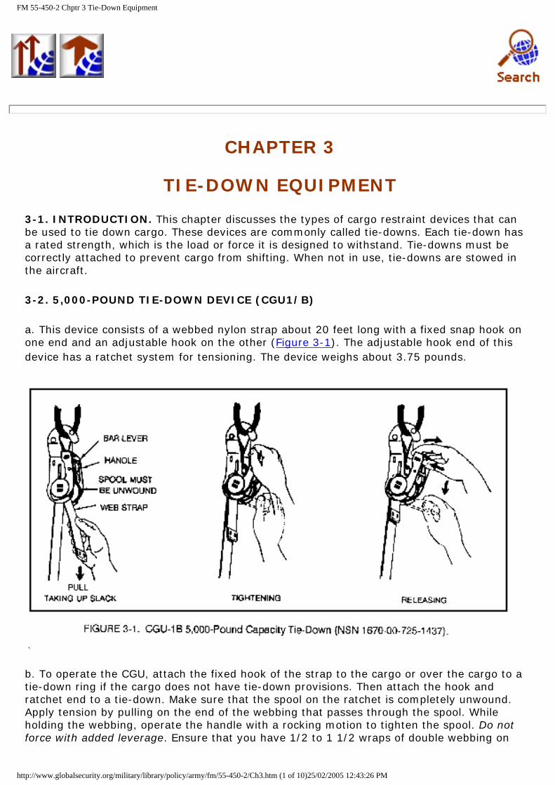
a. This device consists of a webbed nylon strap about 20 feet long with a fixed snap hook on one end and an adjustable hook on the other (Figure 3-1). The adjustable hook end of this device has a ratchet system for tensioning. The device weighs about 3.75 pounds.
b. To operate the CGU, attach the fixed hook of the strap to the cargo or over the cargo to a tie-down ring if the cargo does not have tie-down provisions. Then attach the hook and ratchet end to a tie-down. Make sure that the spool on the ratchet is completely unwound. Apply tension by pulling on the end of the webbing that passes through the spool. While holding the webbing, operate the handle with a rocking motion to tighten the spool. Do not force with added leverage. Ensure that you have 1/2 to 1 1/2 wraps of double webbing on
http://www.globalsecurity.org/military/library/policy/army/fm/55-450-2/Ch3.htm (1 of 10)25/02/2005 12:43:26 PM
FM 55-450-2 Chptr 3 Tie-Down Equipment
the spool. To release, depress the release handle while turning the handle to the full open position.
3-3. 10,000-POUND TIE-DOWN DEVICE (MB-1)
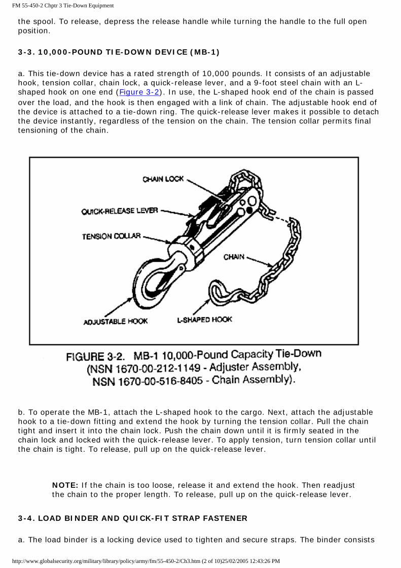
a. This tie-down device has a rated strength of 10,000 pounds. It consists of an adjustable hook, tension collar, chain lock, a quick-release lever, and a 9-foot steel chain with an L-shaped hook on one end (Figure 3-2). In use, the L-shaped hook end of the chain is passed over the load, and the hook is then engaged with a link of chain. The adjustable hook end of the device is attached to a tie-down ring. The quick-release lever makes it possible to detach the device instantly, regardless of the tension on the chain. The tension collar permits final tensioning of the chain.
b. To operate the MB-1, attach the L-shaped hook to the cargo. Next, attach the adjustable hook to a tie-down fitting and extend the hook by turning the tension collar. Pull the chain tight and insert it into the chain lock. Push the chain down until it is firmly seated in the chain lock and locked with the quick-release lever. To apply tension, turn tension collar until the chain is tight. To release, pull up on the quick-release lever.
NOTE: If the chain is too loose, release it and extend the hook. Then readjust the chain to the proper length. To release, pull up on the quick-release lever.
3-4. LOAD BINDER AND QUICK-FIT STRAP FASTENER
a. The load binder is a locking device used to tighten and secure straps. The binder consists
http://www.globalsecurity.org/military/library/policy/army/fm/55-450-2/Ch3.htm (2 of 10)25/02/2005 12:43:26 PM

FM 55-450-2 Chptr 3 Tie-Down Equipment
of the two body plates that attach at one end to a short hook and at the end of a handle that holds a pivoting long hook. Usually, load binders are used to draw up tautly a tie-down strap that is passed through, around, or over cargo items and fitted with a quick-fit strap fastener (except when the quick-fit strap is used as a binder by itself). There are two types of load binders: a 5,000-pound capacity (Figure 3-3) and a 10,000-pound capacity.
b. The quick-fit strap fasteners are fitted on the free ends of the 15-foot tie-down straps to provide a means of securing free ends of the strap to the load binders. Each fastener consists of a metal fitting forged in a V-shape with a double bar and a friction grip crossbar (Figure 3-4).
3-5. NETS
a. MA-2(15-x15-Foot) and MA-3(15-x20-Foot) Cargo Nets. These nets are made of webbed nylon straps and have a restraint capacity of 10,000 pounds each. Fixed straps (about 10
http://www.globalsecurity.org/military/library/policy/army/fm/55-450-2/Ch3.htm (3 of 10)25/02/2005 12:43:26 PM

FM 55-450-2 Chptr 3 Tie-Down Equipment
inches long) equipped with snap hooks are attached to one side of the net. The remaining sides of the net are equipped with adjustable straps about 4 feet long. The adjustable straps are also equipped with snap hooks. Reefing rings and hooks allow the size of the net to be adjusted to the size of the load. The nets may be used to restrain stacks of general cargo, such as boxes, sacks, metal containers, or a combination of miscellaneous items. They are also used with barrier nets. The cargo nets are installed on stacks of general cargo as follows:
(1) Stack cargo in tie-down position.
(2) Unfold MA-2 or MA-3 cargo net and attach fixed straps to tie-down rings.
(3) Adjust position of net to remove slack from fixed straps and fold corners snugly around stack.
(4) To release the net, reverse attachment procedure.
NOTE: When cargo is stacked close to the fuselage wall, pre-position the cargo net and secure it to the fuselage wall as shown in Figure 3-5. After the cargo is stacked, secure the net following the above procedures.
b. Barrier Nets. Barrier nets (Figure 3-6) are used with cargo tie-down nets to secure general cargo and to minimize individual tie-down device requirements. They are used for forward and aft restraint and can restrain 15,000 pounds of cargo in a forward direction at 4 Gs and 40,000 pounds in an aft direction at 1.5 Gs. They also supply vertical and lateral
http://www.globalsecurity.org/military/library/policy/army/fm/55-450-2/Ch3.htm (4 of 10)25/02/2005 12:43:26 PM

FM 55-450-2 Chptr 3 Tie-Down Equipment
restraint. The net system is used to restrain palletized and composite cargo loads when such loads are to be air-landed. However, in nonpalletized loads, any concentrated cargo (heavy object) item must be attached to the cargo floor with appropriate tie-down devices before positioning any lighter items of cargo around it. Securing concentrated cargo prevents its crushing smaller pieces of cargo when the composite load is restrained by the net system. To compensate for the stretch of material, arrange barrier nets to prevent the cargo at the aft end of the restrained group from shifting forward and overloading the barrier net forward (Figure 3-7).
NOTE: Barrier nets for forward or aft restraint should be increased in length in the direction of the load. That is, for forward restraint, the tie-down devices at the forward end should have a greater length than those used toward the aft end.
NOTE: If tie-down fittings are not located to allow longer barrier net straps toward the front of the load for forward restraint, attach to the next available tie-down fitting aft.
CAUTION
Concentrated cargo units must be attached to the cargo floor with tie-down devices with lighter cargo placed around them and the cargo net placed over the complete load.
http://www.globalsecurity.org/military/library/policy/army/fm/55-450-2/Ch3.htm (5 of 10)25/02/2005 12:43:26 PM

FM 55-450-2 Chptr 3 Tie-Down Equipment
http://www.globalsecurity.org/military/library/policy/army/fm/55-450-2/Ch3.htm (6 of 10)25/02/2005 12:43:26 PM

FM 55-450-2 Chptr 3 Tie-Down Equipment
3-6. PADDING. To prevent damage to tie-down straps during operations, any strap hitched next to or resting against an abrasive cargo surface should be wrapped with cellulose wadding, felt padding, or a cushioning material, such as rags, canvas, burlap, or newspapers (anything that will keep the strap from touching cargo) (Figure 3-8). Use tape to secure the padding to the strap to keep vibrations from working it out from under the strap.
3-7. L-SHAPED GRABHOOK
a. Horizontal Tie-Down Provision. When attaching the L-shaped hook end of the chain to a cargo tie-down provision, remember that the hook must be properly engaged with a chain link. The correct method is to pass the hook end over and bring it up under the tie-down point. Keep the hook to the left side of the running end of the chain. Then position the hook on top of the selected link to complete the hookup (Figure 3-9).
b. Perpendicular Tie-down Provision. The correct method to attach the hook end to a perpendicular tie-down provision is to pass the hook end from the left through or around the tie-down provision and bring it back under the running end of the chain. Then position the
http://www.globalsecurity.org/military/library/policy/army/fm/55-450-2/Ch3.htm (7 of 10)25/02/2005 12:43:26 PM

FM 55-450-2 Chptr 3 Tie-Down Equipment
hook on top of the selected link to complete the hookup (Figure 3-10).
NOTE: When properly seated, as shown above, the L-shaped hook will not readily disengage in case slack occurs in the chain. The L-shaped grabhook is part of the MB-1 tie-down chain and not a stand-alone item.
3-8. PALLETS
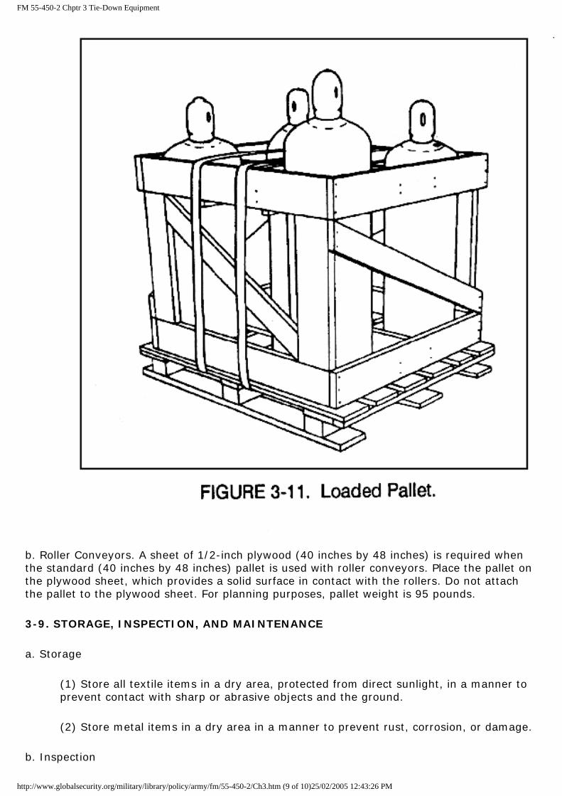
a. Weight Restriction. The gross weight of a loaded pallet will not exceed 2,000 pounds. All pallets will be compatible with Army materials-handling equipment (MHE).
NOTE: Figure 3-11 shows a cylinder container strapped to a warehouse pallet and NOT to the floor of the aircraft.
http://www.globalsecurity.org/military/library/policy/army/fm/55-450-2/Ch3.htm (8 of 10)25/02/2005 12:43:26 PM
FM 55-450-2 Chptr 3 Tie-Down Equipment
b. Roller Conveyors. A sheet of 1/2-inch plywood (40 inches by 48 inches) is required when the standard (40 inches by 48 inches) pallet is used with roller conveyors. Place the pallet on the plywood sheet, which provides a solid surface in contact with the rollers. Do not attach the pallet to the plywood sheet. For planning purposes, pallet weight is 95 pounds.
3-9. STORAGE, INSPECTION, AND MAINTENANCE
a. Storage
(1) Store all textile items in a dry area, protected from direct sunlight, in a manner to prevent contact with sharp or abrasive objects and the ground.
(2) Store metal items in a dry area in a manner to prevent rust, corrosion, or damage.
b. Inspection
http://www.globalsecurity.org/military/library/policy/army/fm/55-450-2/Ch3.htm (9 of 10)25/02/2005 12:43:26 PM

FM 55-450-2 Chptr 3 Tie-Down Equipment
(1) Inspect textile items before and after each use. Inspect webbing for cuts, frays, broken or loose stitching, signs of abrasion or wear, oil, grease, acid, or other foreign matter, such as rust at points of contact with metal parts. Check for presence of cotton buffers where applicable. Make sure that all keepers and/or keeper fittings are present. Any one of the following will be cause for replacement of the component:
(a) The presence of more than two consecutive broken and/or loose stitches.
(b) An accumulation of five broken or loose stitches.
(c) Foreign matter such as rust that cannot be removed by the procedure stated in paragraph 3-9c below.
(d) Frays to the extent that the webbing strands are broken.
(e) Excessive wear or fusing indicated by unusual hardening or softening of webbing fibers.
(f) Cuts of any type.
(2) Inspect metal items for proper operation, rust, corrosion, cracks, bends, distortion, burrs, sharp edges, grease, oil, acid, or any other foreign matter. Inspect each link of all chains. Check for the presence of all nuts, bolts, washers, and spacers.
c. Maintenance
(1) Remove all dirt, dust, or mud from webbing items by drybrushing. Remove grease or oil by spot cleaning with dry-cleaning solvent (tetrachloroethylene, NSN 6810-01-097-2020) and a soft bristled brush or clean cloth. No repairs such as splicing or restitching are authorized.
WARNING
Due to flammable properties and nylon-damaging substances, do not use cleaning solvents other than tetrachloroethylene in spot cleaning cargo nets and nylon sling equipment. Use tetrachloroethylene only in areas where substantial ventilation is available. Repeated or prolonged inhalation of the solvent vapors can be detrimental to human health. Also, avoid prolonged or repeated contact of the solvent fluid with areas of the skin. Tetrachloroethylene must not be taken internally.
(2) Remove all grease, oil, rust, corrosion, acid, or foreign matter on metal items by wiping with a cloth, rubbing with fine emery cloth, or blowing with an air hose. File all burrs and sharp edges. The presence of bends, cracks, or distortion will be cause for replacement.
http://www.globalsecurity.org/military/library/policy/army/fm/55-450-2/Ch3.htm (10 of 10)25/02/2005 12:43:26 PM

FM 55-450-2 Chptr 4 Helicopter Internal Cargo-Handling System (HICHS)
CHAPTER 4
HELICOPTER INTERNAL CARGO-HANDLING SYSTEM (HICHS)
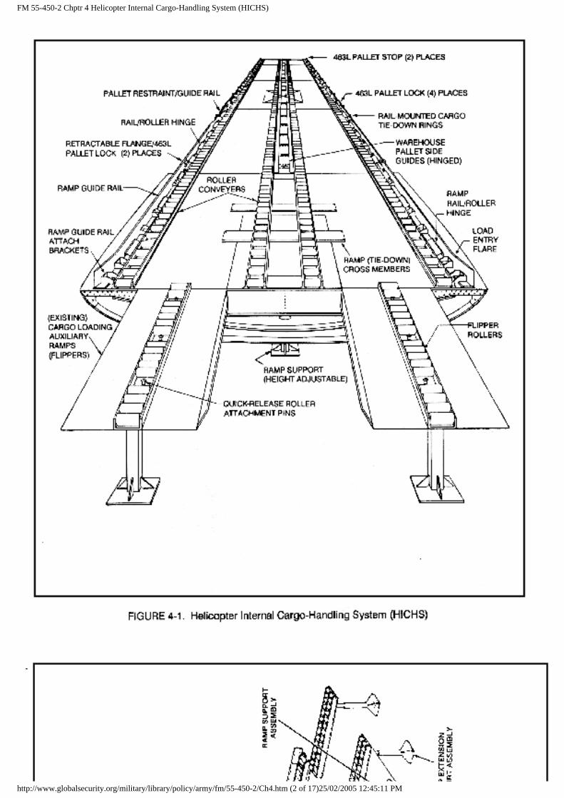
4-1. INTRODUCTION. The helicopter internal cargo-handling system (HICHS) is designed for use in the CH-47 helicopter as a means of loading and unloading various configurations of cargo. This chapter describes the HICHS.
4-2. DESCRIPTION. The functional and physical descriptions of the HICHS are as follows:
a. Functional Description. The HICHS provides low-friction, load/unload conveyor ramps. It also includes conveyors for moving cargo within the aircraft.
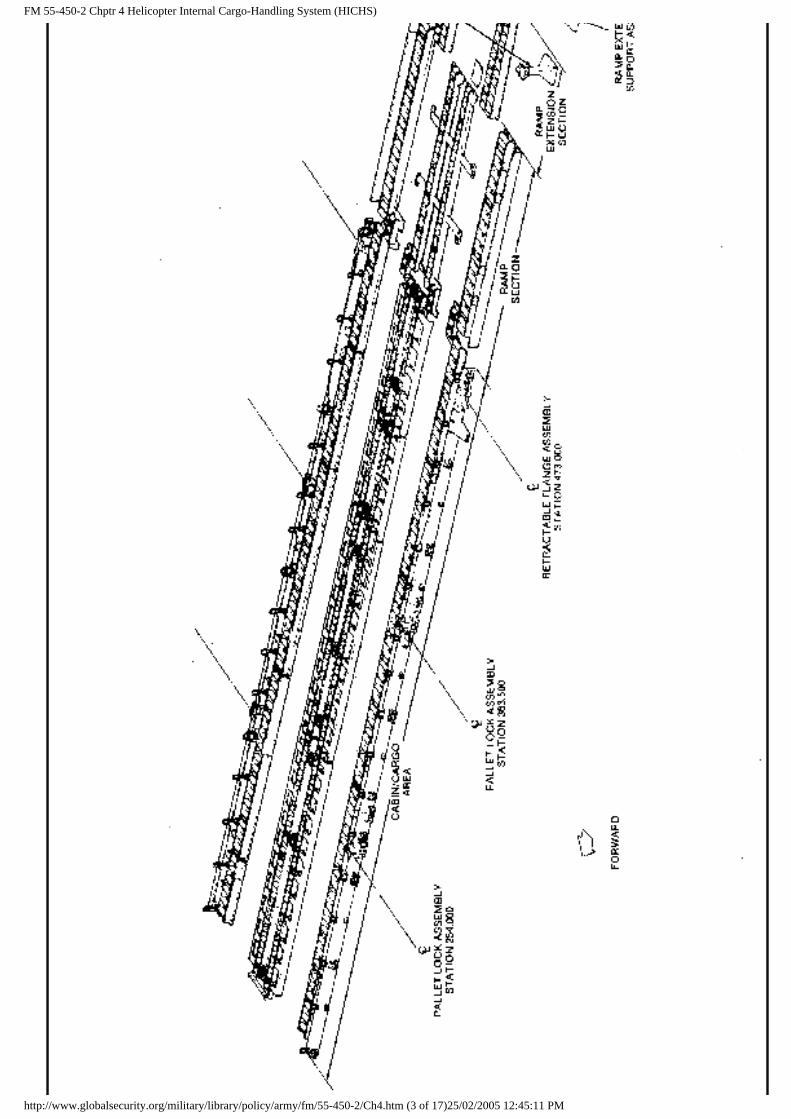
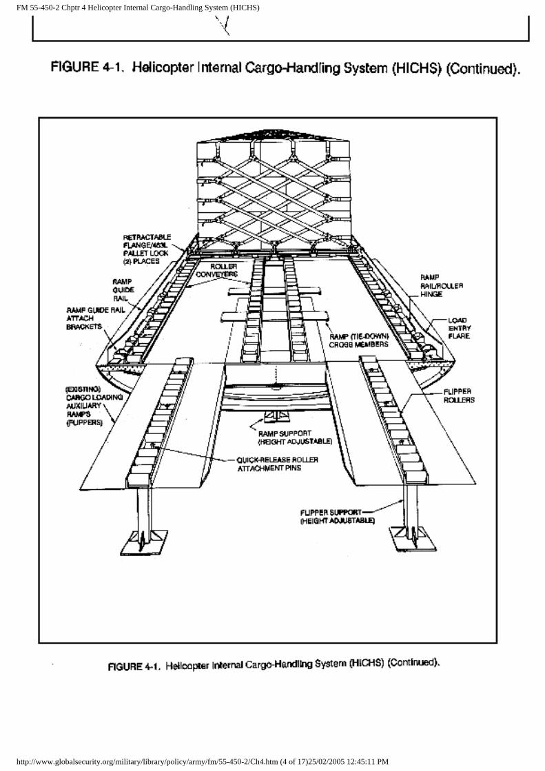
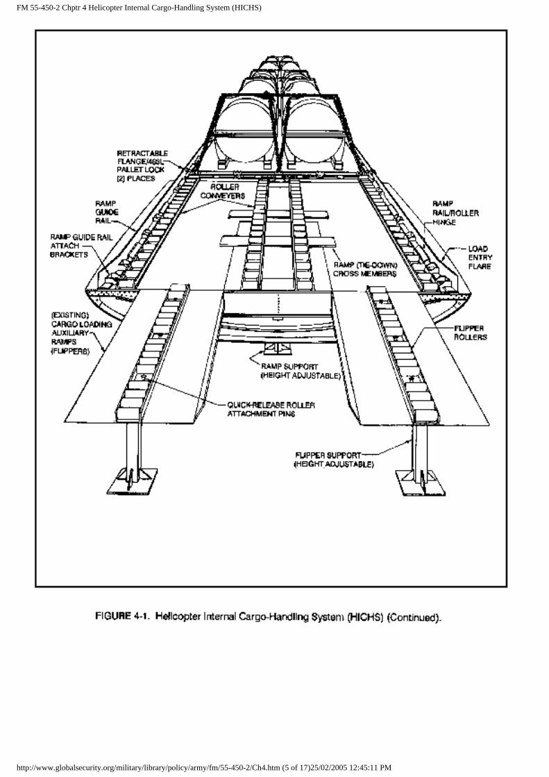
b. Physical Description. The HICHS consists of three major sections. They are the cabin/cargo area, ramp section, and the ramp extension section (Figure 4-1).
http://www.globalsecurity.org/military/library/policy/army/fm/55-450-2/Ch4.htm (1 of 17)25/02/2005 12:45:11 PM
FM 55-450-2 Chptr 4 Helicopter Internal Cargo-Handling System (HICHS)
http://www.globalsecurity.org/military/library/policy/army/fm/55-450-2/Ch4.htm (2 of 17)25/02/2005 12:45:11 PM
FM 55-450-2 Chptr 4 Helicopter Internal Cargo-Handling System (HICHS)
http://www.globalsecurity.org/military/library/policy/army/fm/55-450-2/Ch4.htm (3 of 17)25/02/2005 12:45:11 PM
FM 55-450-2 Chptr 4 Helicopter Internal Cargo-Handling System (HICHS)
http://www.globalsecurity.org/military/library/policy/army/fm/55-450-2/Ch4.htm (4 of 17)25/02/2005 12:45:11 PM
FM 55-450-2 Chptr 4 Helicopter Internal Cargo-Handling System (HICHS)
http://www.globalsecurity.org/military/library/policy/army/fm/55-450-2/Ch4.htm (5 of 17)25/02/2005 12:45:11 PM

FM 55-450-2 Chptr 4 Helicopter Internal Cargo-Handling System (HICHS)
(1) Cabin/Cargo Area. The cabin section of the HICHS consists of three outboard rail/roller assemblies on each side of the cabin. These outboard assemblies are identical but symmetrically opposite. These assemblies use twenty-six 5K tie-down fitting assemblies, eight 10K fitting assemblies, and two tie-down fitting assemblies. Four inboard guide/roller assemblies are mounted in the center of the cabin floor. They are secured with 10 centerline ring plug assemblies to the 5K rings in the floor.
http://www.globalsecurity.org/military/library/policy/army/fm/55-450-2/Ch4.htm (6 of 17)25/02/2005 12:45:11 PM

FM 55-450-2 Chptr 4 Helicopter Internal Cargo-Handling System (HICHS)
(2) Ramp Section. The ramp section of the system includes a right-hand ramp guide assembly and a right-hand ramp inboard guide/roller assembly. There are also symmetrically opposite (left-hand) assemblies. A separate ramp support is provided for use during loading and unloading.
(3) Ramp Extension Section. This section uses two identical ramp extension roller assemblies and separate ramp extension support assemblies.
4-3. INSPECTIONS. Inspect the system components as follows:
a. Intervals. Inspect the HICHS before each mission or when any of the following events has or will occur:
(1) A new cargo-handling system has just been installed.
(2) A cargo system has been removed from storage and installed.
(3) A system has been idle in an out-of-service aircraft.
(4) Maintenance has recently been performed and the system has not been inspected.
(5) A system appears to function improperly.
b. Inspection Criteria. Perform a general inspection for any one of the reasons in paragraph 4-3a above. Inspect regularly to maintain the HICHS in good working condition. Make certain that all components are accounted for in either the installed or stowed locations as applicable. Check outboard rail/roller assemblies, inboard guide/roller assemblies, ramp guide rail/roller assemblies, and ramp extension roller assembly for cracks or breaks. No cracks or breaks are allowed.
4-4. CARGO HANDLING. The HICHS can be used for a variety of cargo.
a. Cargo Range. The HICHS can handle cargo that includes a mixture of pallets, personnel, or vehicles that may be combined. Restrain all cargo to ensure safe operation of the aircraft and the safety of personnel. Restrain the loads according to the procedures and guidelines in TMs 55-450-15 and 55-450-18.
b. Loads. Total load must always be within the normal weight and CG limits as specified in the operational technical orders.
4-5. LOADING. The following are loading sequences for the HICHS.
a. 463L Pallets. Up to three pallets can be winched or manually loaded on the system (maximum 7,500 pounds each).
b. Warehouse Pallets. Use the following loading sequence for warehouse pallets:
(1) Up to 8 to 12 warehouse pallets can be loaded into the aircraft. However, weight and CG requirements must be within limits. The 40-inch side should be positioned
http://www.globalsecurity.org/military/library/policy/army/fm/55-450-2/Ch4.htm (7 of 17)25/02/2005 12:45:11 PM

FM 55-450-2 Chptr 4 Helicopter Internal Cargo-Handling System (HICHS)
across the handling system so that the 48-inch side is on the ramp guide rail. Pallets may be winched or manually loaded.
(2) Pallet combination of 463L and warehouse pallets, as well as other combinations, with vehicular loads can be loaded into the aircraft.
c. Wheeled Vehicles. Winch or manually load the vehicles into the aircraft. For specific procedures, refer to TM 55-450-18.
d. Personnel. The HICHS is compatible for personnel only or both cargo and personnel. If both are loaded, the cargo must be forward of the personnel for safety.
e. Miscellaneous Cargo. Place on a pallet or skid as desired. If a 6/E pallet is used, secure the pallet lock assemblies or retractable flange assemblies. Straps or chains may be used as required.
f. Mixed Cargo. Any of the above cargo may be mixed as desired. The only limitation is space.
4-6. 463L CARGO SYSTEM. In 1957, the USAF adopted a standardized system to facilitate the rapid movement of general cargo aboard airlift aircraft. This 463L system encompasses all phases of cargo loading including MHE, cargo loading platforms, restraint equipment, and in-aircraft systems. The 463L system is the Air Force standard for movement of concentrated cargo. The system is extremely efficient and can reduce ground times by as much as 75 percent.
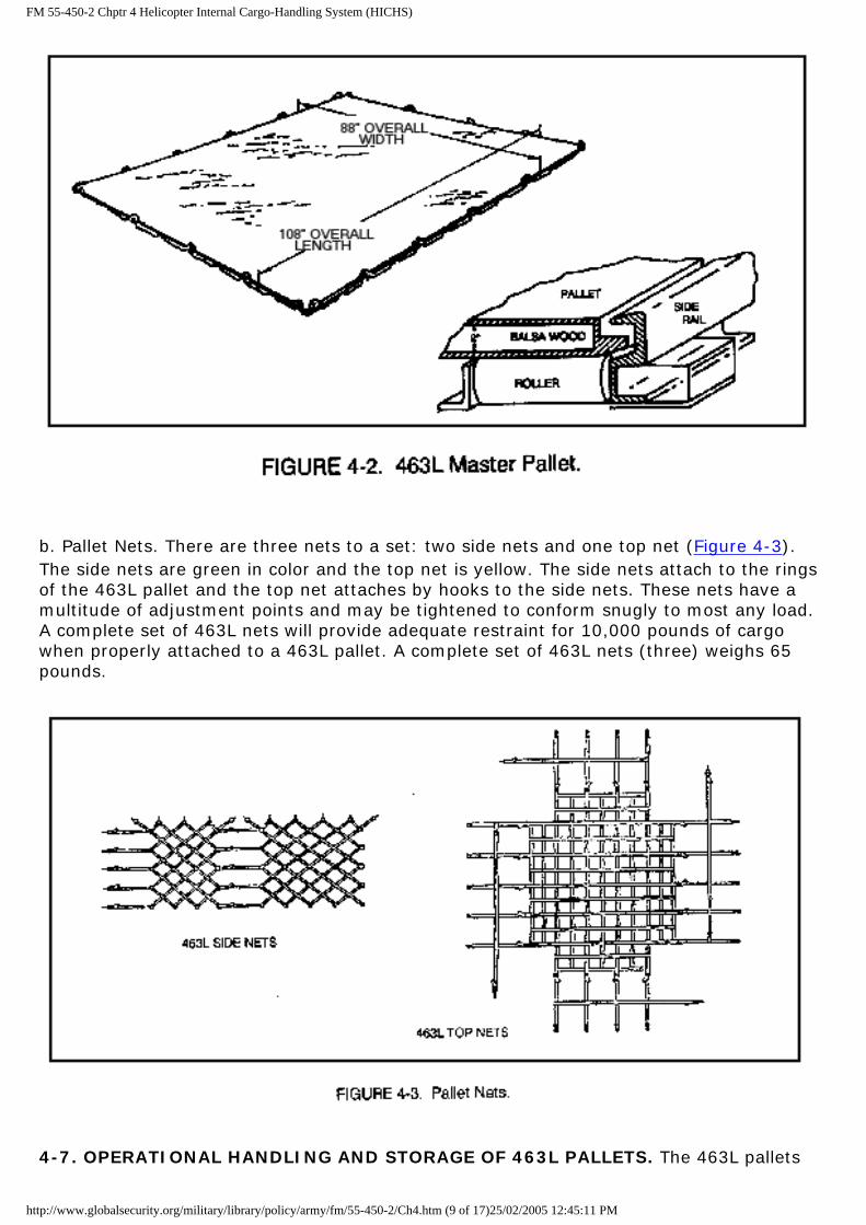
a. Construction. The 463L master pallet (Figure 4-2) is made of corrosion resistant aluminum with soft wood core and is framed on all sides by aluminum rails. The rails have 22 steel tie-down rings attached in such a manner that there are six rings on each long side and five rings on each short side. The rails also have indents (notches) designed to accept the detinet locks located on numerous types of MHE and are found on board all airlift-capable aircraft. The overall dimensions of the 463L pallet are 108 inches wide by 88 inches long and 2 1/4 inches thick. However, the usable dimensions of the upper surface are 104 inches wide by 84 inches long. This allows for 2 inches around the periphery of the pallet to attach straps, nets, or other restraint devices. An empty 463L pallet weighs 290 pounds (355 pounds with nets) and has a maximum load capacity of 10,000 pounds. The maximum pounds per square inch (psi) for the 463L pallet is 250 pounds. Concentrated loading should not exceed 330 pounds on any one square foot. If a load exceeds this amount, then shoring must be used. Each of the 22 tie-down rings has a 7,500-pound restraint capacity.
http://www.globalsecurity.org/military/library/policy/army/fm/55-450-2/Ch4.htm (8 of 17)25/02/2005 12:45:11 PM
FM 55-450-2 Chptr 4 Helicopter Internal Cargo-Handling System (HICHS)
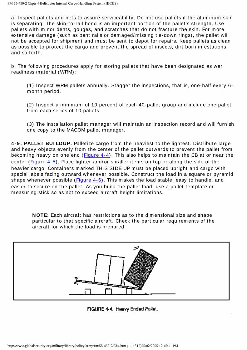
b. Pallet Nets. There are three nets to a set: two side nets and one top net (Figure 4-3). The side nets are green in color and the top net is yellow. The side nets attach to the rings of the 463L pallet and the top net attaches by hooks to the side nets. These nets have a multitude of adjustment points and may be tightened to conform snugly to most any load. A complete set of 463L nets will provide adequate restraint for 10,000 pounds of cargo when properly attached to a 463L pallet. A complete set of 463L nets (three) weighs 65 pounds.
4-7. OPERATIONAL HANDLING AND STORAGE OF 463L PALLETS. The 463L pallets
http://www.globalsecurity.org/military/library/policy/army/fm/55-450-2/Ch4.htm (9 of 17)25/02/2005 12:45:11 PM

FM 55-450-2 Chptr 4 Helicopter Internal Cargo-Handling System (HICHS)
and nets are extremely expensive to purchase and refurbish. With reasonable care and protection, they should last almost indefinitely. The procedures to care for these pallets and nets are simple. Always follow these guidelines:
a. Always put adequate dunnage under 463L pallets by installing a minimum of three 4-inch by 4-inch pieces at least as long as the pallet. This will aid in the movement of the pallets and will protect the lower surface from damage. (Dunnage must accompany the pallets during shipment.)
b. Pallets may be stored in stacks of 40 high. Double stacks (two 20-pallet sets stacked vertically) are authorized for unit/APOE/APOD storage areas, provided they are properly supported. Never stack them upside down for this could damage the rings or the aluminum skinned surface. Only a single stack, properly restrained by 463L nets, may be transported by air. Three pieces of dunnage must be placed between an additional base pallet and the first pallet of the stack provided clearance with the aircraft rail system.
c. Always protect the upper surface of the pallet from sharp-edged cargo. If the cargo you wish to load has any sharp edges or protrusions, install adequate shoring or cushioning materials between the cargo and the pallet to prevent damage.
d. Exercise care when transporting 463L pallets with the forklift tines (forks). The tine tips can easily damage the pallet surface rendering it unusable. The proper and preferred method of handling loaded 463L pallets is with a forklift that has tines measuring at least 72 inches long. Tines 8 inches wide are preferred. Use them whenever possible. Using forklifts with shorter tines, picking up the pallet suspended from the corners with a crane, or other similar methods are not authorized for routine pallet movement. Any deviations shall be authorized by WR-ALC/MMVR.
CAUTION
Forklift operators must ensure cargo load is properly secured to the pallet (using nets, straps, or chains) before moving the pallet.
e. Whenever winching a 463L pallet, always use two attaching points.
f. Never push or slide 463L pallets across any solid surface; to do so will cause damage to the skin.
g. Protect nets from adverse climatic conditions. The netting material will mildew and deteriorate. The metal hooks will also rust if not properly cared for. Hang and dry all nets after use. Never pile wet nets together for storage.
h. Place a plastic barrier between dunnage and the bottom pallet to prevent moisture from penetrating through dunnage to bottom surface of pallets.
i. Because 463L pallets weigh in excess of 270 pounds, movement by hand is unauthorized.
4-8. INSPECTION OF 463L PALLETS
http://www.globalsecurity.org/military/library/policy/army/fm/55-450-2/Ch4.htm (10 of 17)25/02/2005 12:45:11 PM
FM 55-450-2 Chptr 4 Helicopter Internal Cargo-Handling System (HICHS)
a. Inspect pallets and nets to assure serviceability. Do not use pallets if the aluminum skin is separating. The skin-to-rail bond is an important portion of the pallet's strength. Use pallets with minor dents, gouges, and scratches that do not fracture the skin. For more extensive damage (such as bent rails or damaged/missing tie-down rings), the pallet will not be accepted for shipment and must be sent to depot for repairs. Keep pallets as clean as possible to protect the cargo and prevent the spread of insects, dirt born infestations, and so forth.
b. The following procedures apply for storing pallets that have been designated as war readiness material (WRM):
(1) Inspect WRM pallets annually. Stagger the inspections, that is, one-half every 6-month period.
(2) Inspect a minimum of 10 percent of each 40-pallet group and include one pallet from each series of 10 pallets.
(3) The installation pallet manager will maintain an inspection record and will furnish one copy to the MACOM pallet manager.
4-9. PALLET BUILDUP. Palletize cargo from the heaviest to the lightest. Distribute large and heavy objects evenly from the center of the pallet outwards to prevent the pallet from becoming heavy on one end (Figure 4-4). This also helps to maintain the CB at or near the center (Figure 4-5). Place lighter and/or smaller items on top or along the side of the heavier cargo. Containers marked THIS SIDE UP must be placed upright and cargo with special labels facing outward whenever possible. Construct the load in a square or pyramid shape whenever possible (Figure 4-6). This makes the load stable, easy to handle, and easier to secure on the pallet. As you build the pallet load, use a pallet template or measuring stick so as not to exceed aircraft height limitations.
NOTE: Each aircraft has restrictions as to the dimensional size and shape particular to that specific aircraft. Check the particular requirements of the aircraft for which the load is prepared.
http://www.globalsecurity.org/military/library/policy/army/fm/55-450-2/Ch4.htm (11 of 17)25/02/2005 12:45:11 PM

FM 55-450-2 Chptr 4 Helicopter Internal Cargo-Handling System (HICHS)
4-10. MARRIED PALLETS
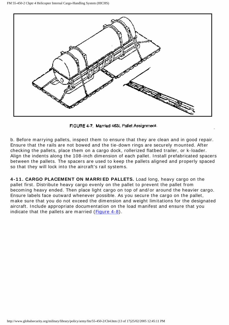
a. In the movement of cargo, you often encounter odd shapes and sizes of cargo that require movement by air. As previously described, the 463L pallet is 108 inches wide by 88 inches long with a maximum cargo weigh capacity of 10,000 pounds. When there is a requirement to ship a piece or pieces of cargo that exceed these dimensions, join two or more pallets together (Figure 4-7). This is referred to as the marrying of pallets (also referred to as double or two pallet trains).
http://www.globalsecurity.org/military/library/policy/army/fm/55-450-2/Ch4.htm (12 of 17)25/02/2005 12:45:11 PM
FM 55-450-2 Chptr 4 Helicopter Internal Cargo-Handling System (HICHS)
b. Before marrying pallets, inspect them to ensure that they are clean and in good repair. Ensure that the rails are not bowed and the tie-down rings are securely mounted. After checking the pallets, place them on a cargo dock, rollerized flatbed trailer, or k-loader. Align the indents along the 108-inch dimension of each pallet. Install prefabricated spacers between the pallets. The spacers are used to keep the pallets aligned and properly spaced so that they will lock into the aircraft's rail systems.
4-11. CARGO PLACEMENT ON MARRIED PALLETS. Load long, heavy cargo on the pallet first. Distribute heavy cargo evenly on the pallet to prevent the pallet from becoming heavy ended. Then place light cargo on top of and/or around the heavier cargo. Ensure labels face outward whenever possible. As you secure the cargo on the pallet, make sure that you do not exceed the dimension and weight limitations for the designated aircraft. Include appropriate documentation on the load manifest and ensure that you indicate that the pallets are married (Figure 4-8).
http://www.globalsecurity.org/military/library/policy/army/fm/55-450-2/Ch4.htm (13 of 17)25/02/2005 12:45:11 PM

FM 55-450-2 Chptr 4 Helicopter Internal Cargo-Handling System (HICHS)
4-12. TIE-DOWN TECHNIQUES. There are many techniques for tying down and lashing cargo. Some key points to remember are--
a. Use a barrier and chain gate (Figure 4-9) for loose, heavy items such as lumber and pipes.
b. Use chains and tie-down devices for large items such as canned engines or palletized
http://www.globalsecurity.org/military/library/policy/army/fm/55-450-2/Ch4.htm (14 of 17)25/02/2005 12:45:11 PM

FM 55-450-2 Chptr 4 Helicopter Internal Cargo-Handling System (HICHS)
wheeled items.
c. Do no attach more than 50 percent of the restraint to the axles of wheeled vehicles.
d. Use 463L net for multiple loose items that fit within the usable dimensions of a single 463L pallet.
e. Use chains for heavy items such as large boxes and vehicles (Figure 4-9).
f. Finally, use 5,000-pound tie-down straps, as required, to provide individual item restraint (Figure 4-10) or to provide supplemental restraint (Figure 4-11) to the 463L nets.
4-13. CARGO NET INSTALLATION. Before using the nets, lay out all the nets and inspect them for serviceability. Do not use any nets that are torn or rotted, or have bad/missing hooks. Only one bad strap/hook in all of those on the net is enough to make the entire net unserviceable.
a. Side Nets
http://www.globalsecurity.org/military/library/policy/army/fm/55-450-2/Ch4.htm (15 of 17)25/02/2005 12:45:11 PM

FM 55-450-2 Chptr 4 Helicopter Internal Cargo-Handling System (HICHS)
(1) Make sure that you have identified the long side (6 hooks) and the short side (5 hooks) of the net, and that the net is right-side up. The net must be right-side up so the bottom hooks will be pointing inward after the nets have been attached to the pallet. If the net is right-side up, the hooks will be facing down as the net is laying on the ground. In addition, many of the nets are marked OUTSIDE.
(2) Place the two side nets around the cargo on the pallet, and hook the hooks into the pallet rings. Recommend starting at one corner and working your way around the pallet. Make sure the straps/hooks of the net cross at the corners of the pallet. Pull the net as high as it will go and hook the two side nets together. Each side net has adjustable straps between the long and short side to make necessary adjustments depending on placement of the cargo. If you have correctly hooked the side nets to the pallet rings, you will have O-rings and tension adjustable hooks to join together, uniting the two side nets. Do not tighten these straps until the side nets are hooked to the top net.
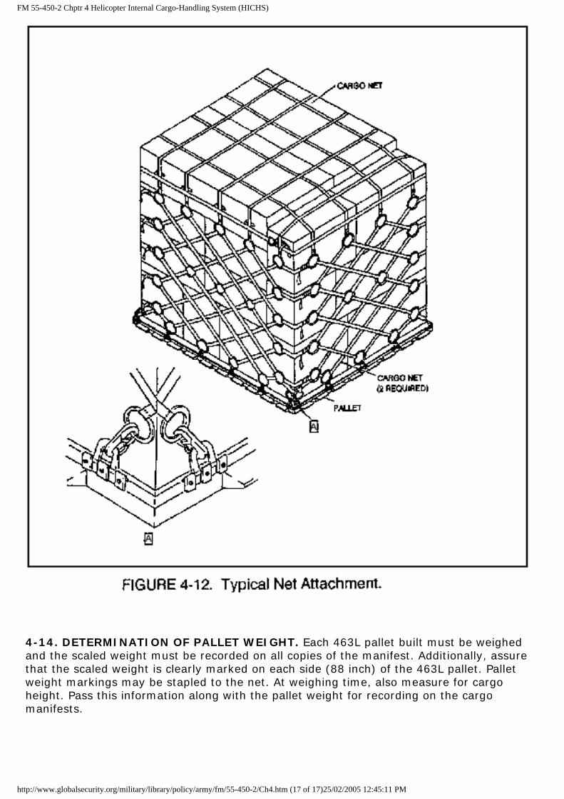
b. Top Net. Place the top net over the cargo making sure that it is centered. The long side of the top net goes with the long side of the side net. Hook the top net into the side nets by using the O-rings. Always use the same row of rings on the side nets to ensure that the top net pulls evenly. When the top net is hooked in, pull evenly on all straps to tighten the top net. Two people should do this to ensure that the net stays even. When all the straps are tightened, including the side net straps, tuck the loose ends of the straps into the netting to prevent snagging on something in the aircraft (Figure 4-12). The most prevalent reason cargo is refused or delayed from loading on an aircraft is poor pallet buildup or netting. If the possibility of inclement weather exists at either departure or arrival airfield, cover the palletized cargo with plastic pallet covering. Now the pallet is ready for weighing.
http://www.globalsecurity.org/military/library/policy/army/fm/55-450-2/Ch4.htm (16 of 17)25/02/2005 12:45:11 PM
FM 55-450-2 Chptr 4 Helicopter Internal Cargo-Handling System (HICHS)
4-14. DETERMINATION OF PALLET WEIGHT. Each 463L pallet built must be weighed and the scaled weight must be recorded on all copies of the manifest. Additionally, assure that the scaled weight is clearly marked on each side (88 inch) of the 463L pallet. Pallet weight markings may be stapled to the net. At weighing time, also measure for cargo height. Pass this information along with the pallet weight for recording on the cargo manifests.
http://www.globalsecurity.org/military/library/policy/army/fm/55-450-2/Ch4.htm (17 of 17)25/02/2005 12:45:11 PM
FM 55-450-2 Chptr 5 Miscellaneous Loading Procedures
CHAPTER 5
MISCELLANEOUS LOADING PROCEDURES
5-1. INTRODUCTION. This chapter discusses the miscellaneous procedures used when loading various types of cargo aboard a helicopter. Knowing these procedures will simplify some of the loading you will be involved in.
5-2. LEAPFROG METHOD OF SHORING
a. Shoring is using lumber to spread the weight of highly concentrated loads over a greater area of the cargo floor than that covered by the cargo alone. It also protects the cargo floor from damage that might be caused by tracked vehicles, steel wheel rims, packing case bands or studs, and rollers. For more information on shoring, see paragraph 6-11.
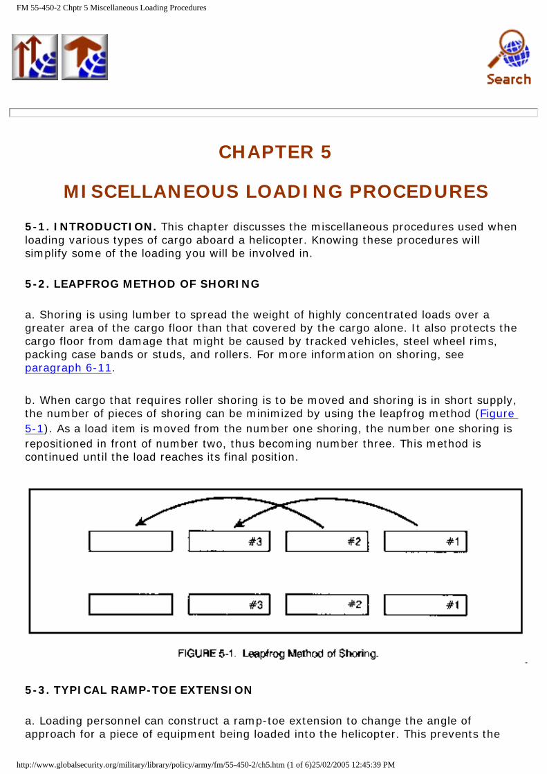
b. When cargo that requires roller shoring is to be moved and shoring is in short supply, the number of pieces of shoring can be minimized by using the leapfrog method (Figure 5-1). As a load item is moved from the number one shoring, the number one shoring is repositioned in front of number two, thus becoming number three. This method is continued until the load reaches its final position.
5-3. TYPICAL RAMP-TOE EXTENSION
a. Loading personnel can construct a ramp-toe extension to change the angle of approach for a piece of equipment being loaded into the helicopter. This prevents the
http://www.globalsecurity.org/military/library/policy/army/fm/55-450-2/ch5.htm (1 of 6)25/02/2005 12:45:39 PM

FM 55-450-2 Chptr 5 Miscellaneous Loading Procedures
equipment from scraping the ground and gouging the ramp. The ramp-toe extension is usually made of 2- x 12-inch lumber (Figure 5-2).
b. To construct a ramp-toe extension, open the helicopter ramp (door) and lower the ramp to the ground. Install the auxiliary ramps to match the tread width of the cargo item. Place two boards of equal length with the forward ends on the helicopter and the rear ends on the ground. Shore the boards by placing pieces of blocking material under each board. The length of space between the ends of the board and the blocking material or between each set of blocking material should be no longer than 4 feet. If a flat board surface on the ramp-toe extension is required, place sheets of plywood on top of the 2- x 12-inch boards. When possible, transport the boards and blocking material with the cargo, since the ramp-toe extension will also be needed during the unloading of the helicopter. Load these items inside the helicopter and secure as directed by a crew member.
NOTE: The length of boards to be used depends on the desired angle of approach into the helicopter. Obtain a smaller angle of approach by using longer boards rather than shorter boards.
5-4. TOWING BRIDLE
a. Towing bridles are used as points of attachment for the winch cable hook on nonpowered items of equipment whose physical characteristics make it impractical to manhandle them into the helicopter. Generally, 10,000-pound capacity tie-down chains are used to form a towing bridle (Figure 5-3). In some instances, 5,000-pound capacity tie-down straps may be used, but only when the items to be loaded are lightweight and the maximum tow stress does not exceed 3,000 pounds.
http://www.globalsecurity.org/military/library/policy/army/fm/55-450-2/ch5.htm (2 of 6)25/02/2005 12:45:39 PM

FM 55-450-2 Chptr 5 Miscellaneous Loading Procedures
b. To form a towing bridle using one tie-down chain, pass the link end of the chain through or around the right point of attachment, then through or around the left point of attachment. Hook one of the end links of the chain in the grabhook.
c. Using two tie-down chains (method 1), pass the link end of one chain through or around the right point of attachment (Figure 5-4). Hook one end link of the chain into the grabhook to form a circle. Pass the link end of the second chain through or around the left attachment point, then through the circle of chain number one. Hook one of the end links of the chain in the grabhook to form a second circle. Attach the helicopter winch cable hook to both chains in the center of the bridle.
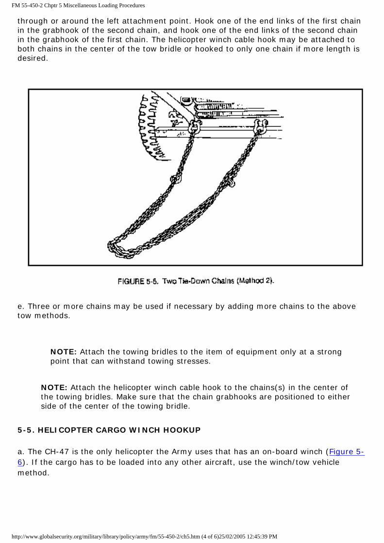
d. Using two tie-down chains (method 2), pass the link end of one chain through or around the right attachment point (Figure 5-5). Pass the link end of the second chain
http://www.globalsecurity.org/military/library/policy/army/fm/55-450-2/ch5.htm (3 of 6)25/02/2005 12:45:39 PM
FM 55-450-2 Chptr 5 Miscellaneous Loading Procedures
through or around the left attachment point. Hook one of the end links of the first chain in the grabhook of the second chain, and hook one of the end links of the second chain in the grabhook of the first chain. The helicopter winch cable hook may be attached to both chains in the center of the tow bridle or hooked to only one chain if more length is desired.
e. Three or more chains may be used if necessary by adding more chains to the above tow methods.
NOTE: Attach the towing bridles to the item of equipment only at a strong point that can withstand towing stresses.
NOTE: Attach the helicopter winch cable hook to the chains(s) in the center of the towing bridles. Make sure that the chain grabhooks are positioned to either side of the center of the towing bridle.
5-5. HELICOPTER CARGO WINCH HOOKUP
a. The CH-47 is the only helicopter the Army uses that has an on-board winch (Figure 5-6). If the cargo has to be loaded into any other aircraft, use the winch/tow vehicle method.
http://www.globalsecurity.org/military/library/policy/army/fm/55-450-2/ch5.htm (4 of 6)25/02/2005 12:45:39 PM

FM 55-450-2 Chptr 5 Miscellaneous Loading Procedures
b. When using the CH-47 on-board winch, center the cargo at the foot of the loading ramp or ramp-toe extension. Lay out the helicopter winch cable and attach the hook to the item of the towing bridle. Always connect the cable hook with the hook pointing up to prevent it from catching or digging into the helicopter floor. A helicopter crew member operates the winch. The unit loading team aids in guiding the items and adjusting shoring. The cargo is pulled into the helicopter and positioned for tie-down.
c. Use the winch/tow vehicle method to load heavy, wheeled, tracked, skid-mounted, or palletized cargo when an aircraft winch is not available or when the weight of the cargo item exceeds the capacity of the aircraft winch. A winch or tow vehicle positioned outside the aircraft provides the power to move the cargo up the aircraft's loading ramp and into position in the cargo compartment. Use snatch blocks in the aircraft to change the direction of pull of the winch/tow vehicle.
(1) When a vehicle with winch is used, power is provided through the winch to move the cargo item. When a tow vehicle (vehicle without winch) is used, power is provided by moving (backing) the vehicle itself. All operations for either procedure, other than the actual use of the winch or backing of the tow vehicle, are identical.
(2) Center the item to be loaded at the foot of the aircraft loading ramp. Secure two snatch blocks to tie-down fittings in the aircraft. (Make sure that the tie-down fittings are not overloaded.) Align one block with the center of the aircraft. Place one block to the side of the aircraft to permit unobstructed passage of the winch or tow cable out of the aircraft. Position the winch or tow vehicle facing the aircraft, centered on the cable extending from the side of the aircraft and slightly to the rear of the cargo item. Then rig and check the winch or tow cable. Move the cargo item into the aircraft by taking up the winch cable onto the winch drum or by slowly backing tow vehicle.
http://www.globalsecurity.org/military/library/policy/army/fm/55-450-2/ch5.htm (5 of 6)25/02/2005 12:45:39 PM

FM 55-450-2 Chptr 5 Miscellaneous Loading Procedures
(3) The loading crew aids in guiding the item into the aircraft and adjusting shoring as necessary.
(4) To prevent damage to the aircraft floor, place small pieces of shoring crosswise on the aircraft floor under the tow cable at points where the cable passes over the aircraft ramp hinge. This acts as a buffer between the cable and the floor.
(5) When attaching the winch/tow cable to the cargo item or vehicle, using a towing bridle may simplify the hookup. Using a clevis to connect the cable end to the bridle will prevent the connections from disengaging during operations.
(6) Before exerting full pulling power on the winch/tow cable, either operate the winch or back the tow vehicle enough to take up all slack in the cable and towing connections. Then halt the operations and inspect the hookup to make sure that--
● The cable is free of kinks or twists.● The cable is properly passed through the snatch blocks. ● The blocks are securely attached to the tie-down fittings. ● The cable is attached firmly to the cargo item (and tow vehicle).
(7) The winch/tow vehicle procedure may be used to load a prime mover and towed load that is to be loaded "towed load first" into an aircraft. This procedure does not eliminate the need for a vehicle driver because he must steer, maneuver, and apply brakes when necessary. This method eases operations where clearances and ramp inclines are critical.
CAUTION
Personnel should avoid being near a cable that is under tension. Serious injury could result if the cable were to snap.
.
http://www.globalsecurity.org/military/library/policy/army/fm/55-450-2/ch5.htm (6 of 6)25/02/2005 12:45:39 PM
FM 55-450-2 Chptr 6 Load Preparation, Loading, And Tie-Down Instructions
CHAPTER 6
LOAD PREPARATION, LOADING, AND
TIE-DOWN INSTRUCTIONS
6-1. INTRODUCTION. This chapter deals with preparing loads. It describes how to determine tie-down requirements and shoring needs. It also shows how to compute the CB of loads and correctly use pallets and rollers.
6-2. RESTRAINT CRITERIA. Tie-down devices secure cargo against forward, rearward, lateral, and vertical movement during takeoff, flight, and landing. To determine the number of devices needed to safely secure a given item of cargo, you must know the--
● Weight of the cargo. ● Restraint criteria for the aircraft. ● Strength of the tie-down devices and fittings. ● Angles of tie to be used.
a. Restraint Factors. Compute restraint criteria for each aircraft to counter the maximum amount of force or thrust that cargo can be expected to exert against tie-downs under operating conditions. Restraint factors are influenced by--
● Acceleration during takeoff. ● Stability during flight. ● Deceleration during landing. ● Type of landing field (improved or unimproved) for which the aircraft is designated.
b. Tie-Downs. The effective holding strength of a device (or fitting) is determined by the rated strength of the item and how it is employed. All tie-downs must be anchored to a tie-down fitting. The strongest tie-down is no stronger than the fitting to which it is attached. If a tie-down is stressed to its breaking point, the fitting is stressed an equal amount up to the full rated strength of the tie-down. Figure 6-1 shows a typical tie-down correct pull-off.
http://www.globalsecurity.org/military/library/policy/army/fm/55-450-2/Ch6.htm (1 of 32)25/02/2005 12:48:14 PM

FM 55-450-2 Chptr 6 Load Preparation, Loading, And Tie-Down Instructions
c. Restraint Nomenclature. Restraints are named for the direction in which they are meant to keep the cargo from moving. Forward restraints keep the cargo from moving forward, aft restraints keep it from moving aft, and lateral restraints keep it from moving side to side. Vertical (downward) restraint is supplied by the cargo floor.
d. Calculation of Tie-Down Devices Required. Use the following method to calculate the number of tie-down devices required to restrain a load from moving in any direction, using the restraint criteria provided:
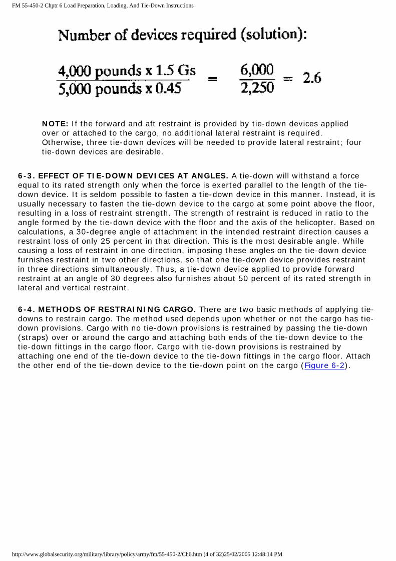
PROBLEM: How many tie-down devices rated at 5,000 pounds will be required to restrain a load weighing 4,000 pounds with tie-down devices at a 30-degree vertical and a 30-degree side angle?
CALCULATION: 1. Forward restraint (formula):
NOTE: Since the equation yields a fractional number, this number is increased to the next whole number. Therefore, five tie-down devices will be required to provide forward restraint; six tie-down devices are desirable.
2. Aft restraint (formula):
http://www.globalsecurity.org/military/library/policy/army/fm/55-450-2/Ch6.htm (2 of 32)25/02/2005 12:48:14 PM

FM 55-450-2 Chptr 6 Load Preparation, Loading, And Tie-Down Instructions
NOTE: Since the equation yields a fractional number, this number is increased to the next whole number. Therefore, three tie-down devices will be required; four tie-down devices are desirable.
3. Vertical restraint (up) (formula):
NOTE: If the forward and aft restraint is provided by tie-down devices applied over the cargo or attached to the cargo, no additional vertical restraint is required. Otherwise, four tie-down devices will be needed to provide vertical restraint.
4. Vertical restraint (down): The floor provides the downward restraint.
5. Lateral restraint (formula):
http://www.globalsecurity.org/military/library/policy/army/fm/55-450-2/Ch6.htm (3 of 32)25/02/2005 12:48:14 PM
FM 55-450-2 Chptr 6 Load Preparation, Loading, And Tie-Down Instructions
NOTE: If the forward and aft restraint is provided by tie-down devices applied over or attached to the cargo, no additional lateral restraint is required. Otherwise, three tie-down devices will be needed to provide lateral restraint; four tie-down devices are desirable.
6-3. EFFECT OF TIE-DOWN DEVICES AT ANGLES. A tie-down will withstand a force equal to its rated strength only when the force is exerted parallel to the length of the tie-down device. It is seldom possible to fasten a tie-down device in this manner. Instead, it is usually necessary to fasten the tie-down device to the cargo at some point above the floor, resulting in a loss of restraint strength. The strength of restraint is reduced in ratio to the angle formed by the tie-down device with the floor and the axis of the helicopter. Based on calculations, a 30-degree angle of attachment in the intended restraint direction causes a restraint loss of only 25 percent in that direction. This is the most desirable angle. While causing a loss of restraint in one direction, imposing these angles on the tie-down device furnishes restraint in two other directions, so that one tie-down device provides restraint in three directions simultaneously. Thus, a tie-down device applied to provide forward restraint at an angle of 30 degrees also furnishes about 50 percent of its rated strength in lateral and vertical restraint.
6-4. METHODS OF RESTRAINING CARGO. There are two basic methods of applying tie-downs to restrain cargo. The method used depends upon whether or not the cargo has tie-down provisions. Cargo with no tie-down provisions is restrained by passing the tie-down (straps) over or around the cargo and attaching both ends of the tie-down device to the tie-down fittings in the cargo floor. Cargo with tie-down provisions is restrained by attaching one end of the tie-down device to the tie-down fittings in the cargo floor. Attach the other end of the tie-down device to the tie-down point on the cargo (Figure 6-2).
http://www.globalsecurity.org/military/library/policy/army/fm/55-450-2/Ch6.htm (4 of 32)25/02/2005 12:48:14 PM
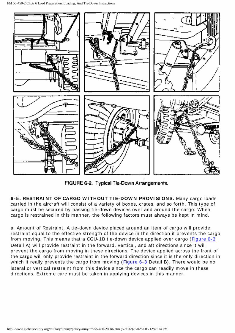
FM 55-450-2 Chptr 6 Load Preparation, Loading, And Tie-Down Instructions
6-5. RESTRAINT OF CARGO WITHOUT TIE-DOWN PROVISIONS. Many cargo loads carried in the aircraft will consist of a variety of boxes, crates, and so forth. This type of cargo must be secured by passing tie-down devices over and around the cargo. When cargo is restrained in this manner, the following factors must always be kept in mind.
a. Amount of Restraint. A tie-down device placed around an item of cargo will provide restraint equal to the effective strength of the device in the direction it prevents the cargo from moving. This means that a CGU-1B tie-down device applied over cargo (Figure 6-3 Detail A) will provide restraint in the forward, vertical, and aft directions since it will prevent the cargo from moving in these directions. The device applied across the front of the cargo will only provide restraint in the forward direction since it is the only direction in which it really prevents the cargo from moving (Figure 6-3 Detail B). There would be no lateral or vertical restraint from this device since the cargo can readily move in these directions. Extreme care must be taken in applying devices in this manner.
http://www.globalsecurity.org/military/library/policy/army/fm/55-450-2/Ch6.htm (5 of 32)25/02/2005 12:48:14 PM

FM 55-450-2 Chptr 6 Load Preparation, Loading, And Tie-Down Instructions
b. Length and Tie-Down Angle of the Tie-Down Devices. A tie-down device should generally be as short as possible and follow as closely as possible the contour of the cargo it is securing to minimize slippage. When tie-down devices are passed over cargo from side to side (Figure 6-3 Detail C), the tie-down device should be as close to 90 degrees as the floor fittings will permit. This is also true of the first two tie-down devices (if there are two) which pass over the cargo in the fore and aft direction. If there are more than two devices in the fore and aft direction, the tie-down angle of the additional devices on the aft side of the cargo should be changed to 45 degrees to obtain additional protection against any tendency the cargo may have to tumble forward. This procedure is particularly important when tying down tall items and composite cargo loads consisting of several stacked boxes. In arranging composite loads, cargo should not be stacked so that it is top heavy. The height of a composite load should not be greater than its length in the longitudinal direction, if it can be avoided.
CAUTION
Tie-down angle should be 45 degrees with this technique. A 30-degree angle will allow cargo to shift.
c. Shifting of Cargo. Since the tie-down devices are not actually attached to the cargo, make sure that the load cannot slip from under the tie-down device. This is especially important when several items are tied together. After the proper number of tie-down devices have been applied to comply with the restraint criteria, always check the load to see if any part of it can slip free(Figure 6-3 and 6-4). In many cases where several items are tied down together, it may be necessary to add more tie-down devices to completely
http://www.globalsecurity.org/military/library/policy/army/fm/55-450-2/Ch6.htm (6 of 32)25/02/2005 12:48:14 PM
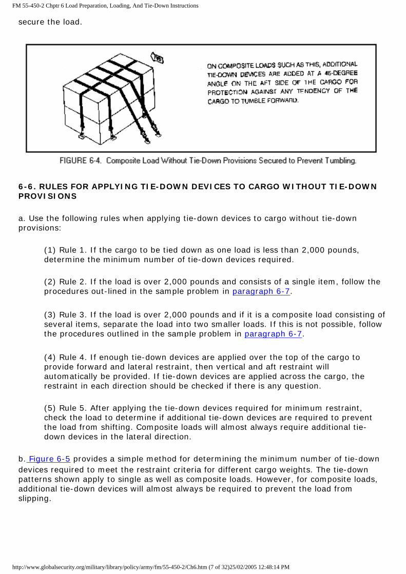
FM 55-450-2 Chptr 6 Load Preparation, Loading, And Tie-Down Instructions
secure the load.
6-6. RULES FOR APPLYING TIE-DOWN DEVICES TO CARGO WITHOUT TIE-DOWN PROVISIONS
a. Use the following rules when applying tie-down devices to cargo without tie-down provisions:
(1) Rule 1. If the cargo to be tied down as one load is less than 2,000 pounds, determine the minimum number of tie-down devices required.
(2) Rule 2. If the load is over 2,000 pounds and consists of a single item, follow the procedures out-lined in the sample problem in paragraph 6-7.
(3) Rule 3. If the load is over 2,000 pounds and if it is a composite load consisting of several items, separate the load into two smaller loads. If this is not possible, follow the procedures outlined in the sample problem in paragraph 6-7.
(4) Rule 4. If enough tie-down devices are applied over the top of the cargo to provide forward and lateral restraint, then vertical and aft restraint will automatically be provided. If tie-down devices are applied across the cargo, the restraint in each direction should be checked if there is any question.
(5) Rule 5. After applying the tie-down devices required for minimum restraint, check the load to determine if additional tie-down devices are required to prevent the load from shifting. Composite loads will almost always require additional tie-down devices in the lateral direction.
b. Figure 6-5 provides a simple method for determining the minimum number of tie-down devices required to meet the restraint criteria for different cargo weights. The tie-down patterns shown apply to single as well as composite loads. However, for composite loads, additional tie-down devices will almost always be required to prevent the load from slipping.
http://www.globalsecurity.org/military/library/policy/army/fm/55-450-2/Ch6.htm (7 of 32)25/02/2005 12:48:14 PM

FM 55-450-2 Chptr 6 Load Preparation, Loading, And Tie-Down Instructions
6-7. SAMPLE PROBLEM FOR SECURING CARGO WITHOUT TIE-DOWN PROVISIONS. Determine the amount of tie-down devices required to properly secure a composite load of 1,800 pounds.
a. Determine the amount of forward and lateral restraint. Refer to Rule 4, paragraph 6-6.
1,800 x 4.0 Gs = 7,200 pounds of forward restraint.
1,800 x 1.5 Gs = 2,700 pounds of lateral restraint.
b. Determine the minimum number of tie-down devices necessary for the required restraint.
c. Apply tie-down devices to the load.
http://www.globalsecurity.org/military/library/policy/army/fm/55-450-2/Ch6.htm (8 of 32)25/02/2005 12:48:14 PM
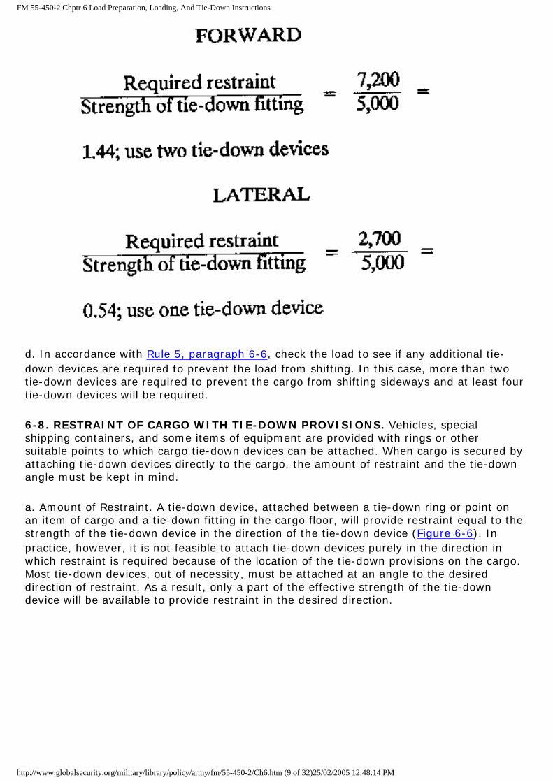
FM 55-450-2 Chptr 6 Load Preparation, Loading, And Tie-Down Instructions
d. In accordance with Rule 5, paragraph 6-6, check the load to see if any additional tie-down devices are required to prevent the load from shifting. In this case, more than two tie-down devices are required to prevent the cargo from shifting sideways and at least four tie-down devices will be required.
6-8. RESTRAINT OF CARGO WITH TIE-DOWN PROVISIONS. Vehicles, special shipping containers, and some items of equipment are provided with rings or other suitable points to which cargo tie-down devices can be attached. When cargo is secured by attaching tie-down devices directly to the cargo, the amount of restraint and the tie-down angle must be kept in mind.
a. Amount of Restraint. A tie-down device, attached between a tie-down ring or point on an item of cargo and a tie-down fitting in the cargo floor, will provide restraint equal to the strength of the tie-down device in the direction of the tie-down device (Figure 6-6). In practice, however, it is not feasible to attach tie-down devices purely in the direction in which restraint is required because of the location of the tie-down provisions on the cargo. Most tie-down devices, out of necessity, must be attached at an angle to the desired direction of restraint. As a result, only a part of the effective strength of the tie-down device will be available to provide restraint in the desired direction.
http://www.globalsecurity.org/military/library/policy/army/fm/55-450-2/Ch6.htm (9 of 32)25/02/2005 12:48:14 PM

FM 55-450-2 Chptr 6 Load Preparation, Loading, And Tie-Down Instructions
b. Tie-Down Angle. The tie-down angle is very important because it determines the amount of restraint that can be obtained in any direction. To lessen the number of tie-down devices and to simplify the calculation of the number of tie-down devices required to restrain a load, apply all tie-down devices as closely as possible to the two 30-degree tie-down angles. In tying down cargo, apply at least four tie-down devices at an angle of 30 degrees to the cargo floor and 30 degrees to the longitudinal axis of the aircraft to provide restraint in all directions. If additional restraint is needed in the forward direction, apply additional devices at the same tie-down angles or at an angle 30 degrees to the cargo floor and 0 degree to the longitudinal axis of the aircraft. These devices do not provide any lateral restraint. They do, however, concentrate more restraint in the forward direction than a tie-down device applied at a 30-degree vertical and 30-degree side tie-down angle. It is for this reason that this tie-down angle is used.
c. Percentage Restraint Chart. See Table 6-1.
http://www.globalsecurity.org/military/library/policy/army/fm/55-450-2/Ch6.htm (10 of 32)25/02/2005 12:48:14 PM

FM 55-450-2 Chptr 6 Load Preparation, Loading, And Tie-Down Instructions
(1) Angles across the top are those formed between the tie-down device and the cabin floor.
(2) Angles down the side are those formed between the tie-down device and the longitudinal axis of the aircraft.
http://www.globalsecurity.org/military/library/policy/army/fm/55-450-2/Ch6.htm (11 of 32)25/02/2005 12:48:14 PM

FM 55-450-2 Chptr 6 Load Preparation, Loading, And Tie-Down Instructions
(3) Vertical restraint is related only to the angle between the tie-down device and the cabin floor. The lateral angle has no bearing on it.
(4) The unshaded area indicates the "best compromise" position.
6-9. RULES FOR APPLYING TIE-DOWN DEVICES ON CARGO WITH TIE-DOWN PROVISIONS. The rules used when applying tie-down devices to cargo with tie-down provisions are as follows:
a. Rule 1. Always apply an even number of tie-down devices, attached in pairs, for forward and aft restraint (Figure 6-7).
b. Rule 2. Apply the tie-down devices as close as possible to the rule-of-thumb tie-down angles. Apply the first four tie-down devices so that the tie-down angle is 30 degrees with the cargo floor and 30 degrees with the longitudinal axis of the helicopter.
c. Rule 3. If the tie-down devices can be applied at the rule-of-thumb tie-down angles, determine the number of tie-downs required to provide restraint.
d. Rule 4. If the tie-down devices cannot be applied at the rule-of-thumb angles, follow
http://www.globalsecurity.org/military/library/policy/army/fm/55-450-2/Ch6.htm (12 of 32)25/02/2005 12:48:14 PM
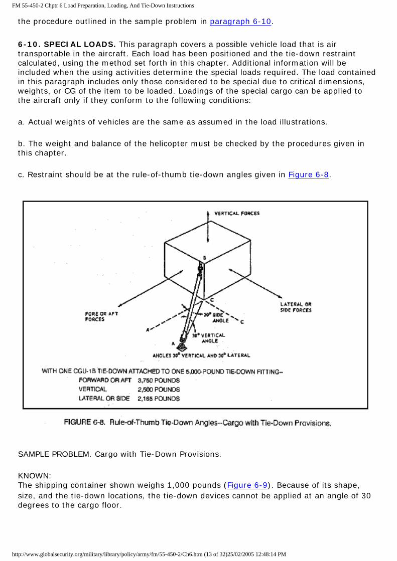
FM 55-450-2 Chptr 6 Load Preparation, Loading, And Tie-Down Instructions
the procedure outlined in the sample problem in paragraph 6-10.
6-10. SPECIAL LOADS. This paragraph covers a possible vehicle load that is air transportable in the aircraft. Each load has been positioned and the tie-down restraint calculated, using the method set forth in this chapter. Additional information will be included when the using activities determine the special loads required. The load contained in this paragraph includes only those considered to be special due to critical dimensions, weights, or CG of the item to be loaded. Loadings of the special cargo can be applied to the aircraft only if they conform to the following conditions:
a. Actual weights of vehicles are the same as assumed in the load illustrations.
b. The weight and balance of the helicopter must be checked by the procedures given in this chapter.
c. Restraint should be at the rule-of-thumb tie-down angles given in Figure 6-8.
SAMPLE PROBLEM. Cargo with Tie-Down Provisions.
KNOWN:The shipping container shown weighs 1,000 pounds (Figure 6-9). Because of its shape, size, and the tie-down locations, the tie-down devices cannot be applied at an angle of 30 degrees to the cargo floor.
http://www.globalsecurity.org/military/library/policy/army/fm/55-450-2/Ch6.htm (13 of 32)25/02/2005 12:48:14 PM
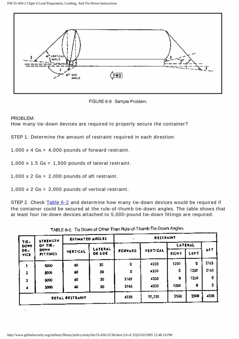
FM 55-450-2 Chptr 6 Load Preparation, Loading, And Tie-Down Instructions
PROBLEM: How many tie-down devices are required to properly secure the container?
STEP 1. Determine the amount of restraint required in each direction.
1,000 x 4 Gs = 4,000 pounds of forward restraint.
1,000 x 1.5 Gs = 1,500 pounds of lateral restraint.
1,000 x 2 Gs = 2,000 pounds of aft restraint.
1,000 x 2 Gs = 2,000 pounds of vertical restraint.
STEP 2. Check Table 6-2 and determine how many tie-down devices would be required if the container could be secured at the rule-of-thumb tie-down angles. The table shows that at least four tie-down devices attached to 5,000-pound tie-down fittings are required.
http://www.globalsecurity.org/military/library/policy/army/fm/55-450-2/Ch6.htm (14 of 32)25/02/2005 12:48:14 PM

FM 55-450-2 Chptr 6 Load Preparation, Loading, And Tie-Down Instructions
STEP 3. Tie down the container with the number of tie-down devices determined in Step 2. Apply the tie-down devices as close as possible to the rule-of-thumb tie-down angles.
STEP 4. Construct a table similar to the one shown and estimate the tie-down angle for each tie-down device.
STEP 5. Obtain the amount of restraint provided by each tie-down device, and add the results to determine how much restraint is actually provided in each direction.
STEP 6. Compare the actual restraint found in Step 5 with the restraint required found in Step 1. If the actual restraint is less, add more tie-down devices and continue the procedure until sufficient restraint is obtained. In this case, no additional tie-down devices are required since the actual restraint is greater than the required restraint.
6-11. SHORING. Shoring is a method of using lumber, planking, or similar material to spread highly concentrated loads over a greater floor area than that occupied by the cargo alone. It also protects the cargo floor from damage caused by tracked vehicle cleats, steel wheel rims, and packing case bands or studs. Shoring size is determined by the cargo to be carried and the floor strength of the helicopter carrying it. In general, 2 inches by 8, 10, or 12 inches of shoring can best be used. Lengths of shoring may vary depending on the intended use. For ease of handling, length should not exceed 12 feet. Plywood sheets of various thicknesses and sizes may be used when practical. Since shoring is used both to load and unload, it will be transported with the cargo and tied down as directed by the aircrew. Include shoring weight with the cargo weight to accurately determine cargo CG. Since all aircraft have relatively fragile flooring, place particular emphasis on proper distribution of cargo weight. A cargo item that has a small bearing area on the cargo floor in comparison with its weight may exceed the aircraft floor strength and require shoring.
NOTE:The structure limits of the flooring for a particular aircraft are found in the aircraft operator's -10 manual.
a. Load Spreaders. Load spreaders (shoring) are support placed beneath an object to increase floor bearing area to prevent excessive concentration of weight. As Figure 6-9 shows, the weight of a load resting on shoring is not spread over the entire shoring area. It is increased over an area extending from the point of contact at a 45-degree angle until it contacts the surface on which the shoring rests. Inspect shoring before it is used to make sure that it is clean, sound, and fit for its intended purpose. Defects in shoring reduce its effectiveness. If the shoring has a split in it, the weight of the cargo will not be transferred past the split, as shown in Figure 6-10. If the shoring is not wide enough, the cargo area is not spread past the edge of the shoring.
http://www.globalsecurity.org/military/library/policy/army/fm/55-450-2/Ch6.htm (15 of 32)25/02/2005 12:48:14 PM

FM 55-450-2 Chptr 6 Load Preparation, Loading, And Tie-Down Instructions
b. Shoring Requirements
(1) To determine the need for shoring or load spreaders for a given load, consider only the area of contact with the floor. In calculating the contact area for rectangular-shaped loads, multiply the width of the item by the length. As an example of load spreading, assume that the plank is 2 inches thick and the box is 12 inches long by 6 inches wide. The area of contact between the box and the plank will be 6 by 12 inches, or 72 square inches. Now extend imaginary planes downward and outward from the edges of the bottom of the box at a 45-degree angle. Where these imaginary planes intersect the cargo floor, the area of contact will be 10 by 16 inches, or 160 square inches. In this case, the area of contact has been more than doubled--an increase of 122 percent. The proportioned increase, however, will not always be so great. When 2-inch-thick shoring is used, that area over which the load is distributed is enlarged by a border 2 inches wide all around the area of load and shoring contact. This border is as wide as the shoring is thick. Thus, if the shoring is 1 inch thick, the load-bearing border added is 1 inch wide. If the shoring is 3 inches thick, the load-bearing border added is 3 inches wide, and so forth. But as a general rule, the use of shoring more than 4 inches thick is not practical. The relationship between border width and shoring thickness applies to all shoring. Since the increase in area occurs only around the perimeter of the load/shoring contact area, the larger the contact area, the smaller the proportional increase in contact area. For example, shoring 2 inches thick under a box 12 inches square will increase the area of contact 77 percent by adding 112 square inches to the original 144 square inches. Shoring 2 inches thick under a box 60 inches square will increase the contact area by only about 14 percent by adding 494 square inches to the original 3,600 square inches. The spreading effect of simple shoring is the same regardless of the shape of the area of contact.
(2) Since the vehicle weight is transmitted through the wheels, it is necessary to know the tire pad or "footprint" area made by pneumatic and hard rubber tires contact with the cargo floor. When vehicles with hard rubber tires roll onto the cargo floor, stresses are created that are far more critical than those created by vehicles with pneumatic tires. The pressures here are concentrated along a thin ribbon of contact at each wheel. The length of this ribbon (the width of the tire) then becomes important in calculating load distribution.
http://www.globalsecurity.org/military/library/policy/army/fm/55-450-2/Ch6.htm (16 of 32)25/02/2005 12:48:14 PM

FM 55-450-2 Chptr 6 Load Preparation, Loading, And Tie-Down Instructions
(3) Figure 6-11 shows the procedure for determining the pressure exerted over a given area by vehicles with rubber tires. The majority of vehicles transported, for example, those with pneumatic tires, do not exceed unit floor and ramp load maximums and thus do not require shoring. Again assuming that the shoring is 2 inches thick, the area of weight distribution of the footprint is enlarged proportionally by the shoring thickness, which will add a 2-inch border. If the original tire footprint is 12 by 6 inches with a formula area of 56.6 square inches, the addition made by the 2-inch border increases the area over which the load is spread to 16 by 10 inches with a formula area of 125 square inches.
6-12. ITEM WEIGHT. There are several ways of finding the weight of an item. One is to look it up in TB 55-46-1. This publication gives the dimensions and weight of almost every item the military has. If you do not have the technical bulletin but do have access to a scale, you can weigh the item. If the item is too big to manhandle onto a scale, load it on a vehicle and then weigh it on a vehicle scale.
6-13. CENTER OF BALANCE
a. The CB of items offered as cargo must be determined to accurately compute the weight and balance condition of a loaded aircraft. The agency offering cargo for air shipment marks each item of cargo with the correct gross weight and a CB point as follows: any item measuring 10 feet or longer and any item having a balance point other than its center. In addition, vehicle-type cargo having a load-carrying capability will be marked indicating an empty or loaded CB, as appropriate. Items not marked as outlined above will not be accepted for airlift as unknown weight/CB presents an unsafe condition relative to aircraft weight and balance.
b. To correctly plan an airlift and segregate loads for individual aircraft, weights and CB of cargo units must be determined. There are two main divisions: vehicles and general cargo.
http://www.globalsecurity.org/military/library/policy/army/fm/55-450-2/Ch6.htm (17 of 32)25/02/2005 12:48:14 PM
FM 55-450-2 Chptr 6 Load Preparation, Loading, And Tie-Down Instructions
(1) The weight and CB of a vehicle must be determined after all secondary cargo is secured as it is to be airlifted. Secondary loads are items of baggage or cargo transported in truck beds and trailers. They must be included in the total weight of the vehicle. Nothing can be added to or removed from a vehicle that has been weighed and marked unless it is reweighed.
(2) The following terms are used to calculate CB of a vehicle:
● Reference datum line (RDL)--predetermined point from which all measurements are taken.
● Front overhang (FOH)--distance in inches from front bumper to center of front axle.
● Wheel base (WB)--distance in inches from center of front axle to center of rear axle or center of tandem axles.
● Rear overhang (ROH)--distance from rear or center of tandem axles to rear bumper.
● Front axle weight (FAW)--pounds.
● Rear axle weight (RAW)--pounds.
● Moment--the product obtained in multiplying the weight by the distance (in inches) from the RDL.
http://www.globalsecurity.org/military/library/policy/army/fm/55-450-2/Ch6.htm (18 of 32)25/02/2005 12:48:14 PM

FM 55-450-2 Chptr 6 Load Preparation, Loading, And Tie-Down Instructions
c. The computation formula is illustrated below showing examples of different types of vehicles and possible loads. Before beginning the process, the unit movement officer must make sure that scales used for weighing are calibrated.
(1) Compute the CB location of vehicles using this formula: Multiply weight by distance (in inches) of each axle from the reference line, then divide the total results by the vehicle gross weight. The resulting figure is the number of inches to be measured aft from the reference line to the CB of the vehicle.
http://www.globalsecurity.org/military/library/policy/army/fm/55-450-2/Ch6.htm (19 of 32)25/02/2005 12:48:14 PM
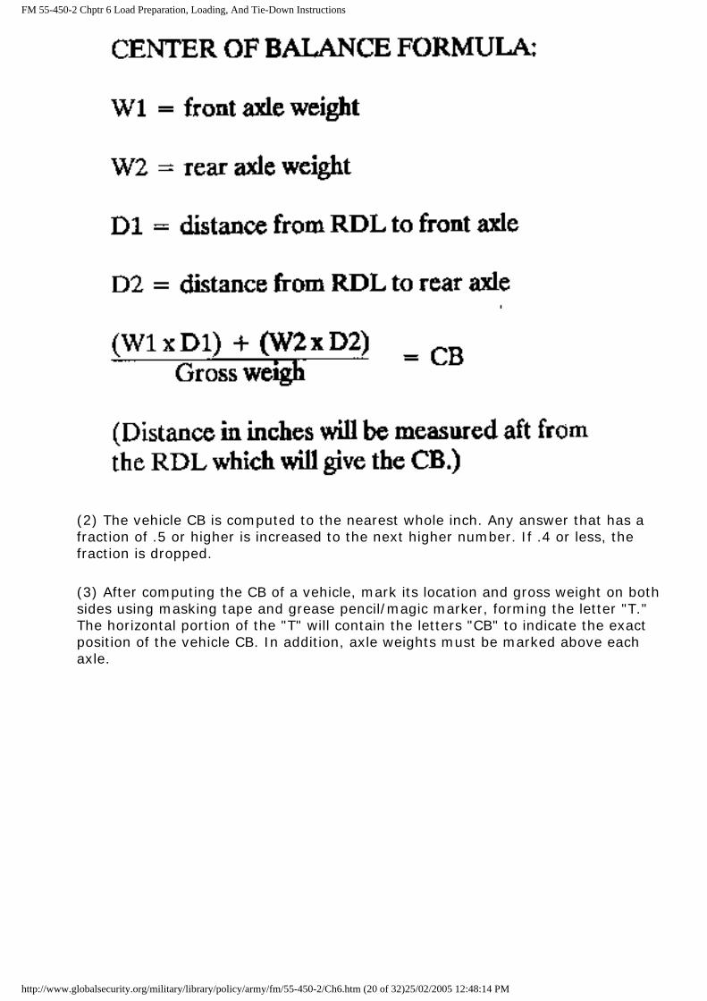
FM 55-450-2 Chptr 6 Load Preparation, Loading, And Tie-Down Instructions
(2) The vehicle CB is computed to the nearest whole inch. Any answer that has a fraction of .5 or higher is increased to the next higher number. If .4 or less, the fraction is dropped.
(3) After computing the CB of a vehicle, mark its location and gross weight on both sides using masking tape and grease pencil/magic marker, forming the letter "T." The horizontal portion of the "T" will contain the letters "CB" to indicate the exact position of the vehicle CB. In addition, axle weights must be marked above each axle.
http://www.globalsecurity.org/military/library/policy/army/fm/55-450-2/Ch6.htm (20 of 32)25/02/2005 12:48:14 PM

FM 55-450-2 Chptr 6 Load Preparation, Loading, And Tie-Down Instructions
(4) The following illustrations show examples of methods used to determine the weight and CB location of typical cargo units. These cargo units include general cargo, large or skid-mounted cargo, track-type vehicles, and single- and multiple-axle vehicles.
EXAMPLE 1--Vehicles
STEP 1. Determine front and rear axle weights.
STEP 2. Determine distance from the front and rear axles to the RDL.
http://www.globalsecurity.org/military/library/policy/army/fm/55-450-2/Ch6.htm (21 of 32)25/02/2005 12:48:14 PM
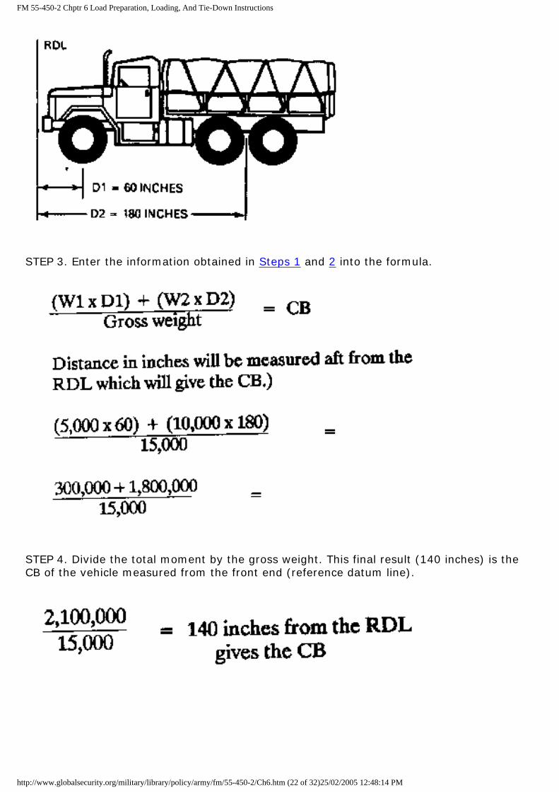
FM 55-450-2 Chptr 6 Load Preparation, Loading, And Tie-Down Instructions
STEP 3. Enter the information obtained in Steps 1 and 2 into the formula.
STEP 4. Divide the total moment by the gross weight. This final result (140 inches) is the CB of the vehicle measured from the front end (reference datum line).
http://www.globalsecurity.org/military/library/policy/army/fm/55-450-2/Ch6.htm (22 of 32)25/02/2005 12:48:14 PM

FM 55-450-2 Chptr 6 Load Preparation, Loading, And Tie-Down Instructions
EXAMPLE 2--Trailers
The same idea is used in determining the CB for a trailer as was used for the truck in Example 1. The main difference is that the tongue is weighed as the front axle and the actual axle is weighed as the rear axle.
STEP 1. Weigh tongue and axle.
STEP 2. Measure the distance from the end of the tongue to the center of the axle.
http://www.globalsecurity.org/military/library/policy/army/fm/55-450-2/Ch6.htm (23 of 32)25/02/2005 12:48:14 PM

FM 55-450-2 Chptr 6 Load Preparation, Loading, And Tie-Down Instructions
STEP 3. Enter the weights.
STEP 4. Now measure 77 inches from the tongue aft to obtain the CB on the trailer.
http://www.globalsecurity.org/military/library/policy/army/fm/55-450-2/Ch6.htm (24 of 32)25/02/2005 12:48:14 PM

FM 55-450-2 Chptr 6 Load Preparation, Loading, And Tie-Down Instructions
EXAMPLE 3--Multiaxle vehicles
STEP 1. To determine the CB for a multiaxle vehicle such as the one shown here, first weigh each axle as in Step 1 in Example 1.
STEP 2. Then measure the distance from the RDL to each axle as was done in Step 2.
http://www.globalsecurity.org/military/library/policy/army/fm/55-450-2/Ch6.htm (25 of 32)25/02/2005 12:48:14 PM

FM 55-450-2 Chptr 6 Load Preparation, Loading, And Tie-Down Instructions
STEP 3. Now as before, enter the information obtained in Steps 1 and 2 into the formula.
STEP 4. Divide the total moment by the total weight.
http://www.globalsecurity.org/military/library/policy/army/fm/55-450-2/Ch6.htm (26 of 32)25/02/2005 12:48:14 PM

FM 55-450-2 Chptr 6 Load Preparation, Loading, And Tie-Down Instructions
EXAMPLE 4--Tracked vehicles
STEP 1. To determine weight, drive the vehicle onto a platform scale (truck scale, coal yard scale, and so forth) large enough to accommodate the entire vehicle. Record weight.
STEP 2. To determine CB, drive the vehicle onto a wooden beam or pole until it tilts forward. Mark the side of the vehicle at the point of tilt.
http://www.globalsecurity.org/military/library/policy/army/fm/55-450-2/Ch6.htm (27 of 32)25/02/2005 12:48:14 PM
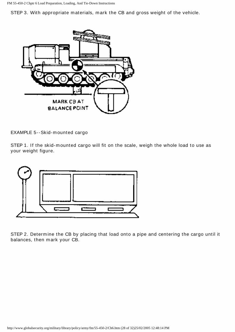
FM 55-450-2 Chptr 6 Load Preparation, Loading, And Tie-Down Instructions
STEP 3. With appropriate materials, mark the CB and gross weight of the vehicle.
EXAMPLE 5--Skid-mounted cargo
STEP 1. If the skid-mounted cargo will fit on the scale, weigh the whole load to use as your weight figure.
STEP 2. Determine the CB by placing that load onto a pipe and centering the cargo until it balances, then mark your CB.
http://www.globalsecurity.org/military/library/policy/army/fm/55-450-2/Ch6.htm (28 of 32)25/02/2005 12:48:14 PM

FM 55-450-2 Chptr 6 Load Preparation, Loading, And Tie-Down Instructions
EXAMPLE 6--Skid-mounted cargo
If the skid-mounted cargo is too large to fit on the scale at one time, it will have to be weighed and measured as in Examples 1 and 2, using the same formula.
NOTE: The points to use as the axles should be support braces between the skids, as shown here.
http://www.globalsecurity.org/military/library/policy/army/fm/55-450-2/Ch6.htm (29 of 32)25/02/2005 12:48:14 PM

FM 55-450-2 Chptr 6 Load Preparation, Loading, And Tie-Down Instructions
Now go through Steps 1 through 3 as before in Examples 1 and 2.
STEP 1. Support the overhang at the same height as the scale with a block of wood.
STEP 2. Measure the distance from the RDL to the front and rear points of support (same as axles).
http://www.globalsecurity.org/military/library/policy/army/fm/55-450-2/Ch6.htm (30 of 32)25/02/2005 12:48:14 PM
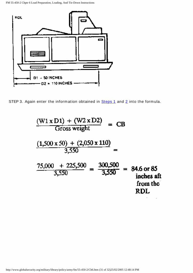
FM 55-450-2 Chptr 6 Load Preparation, Loading, And Tie-Down Instructions
STEP 3. Again enter the information obtained in Steps 1 and 2 into the formula.
http://www.globalsecurity.org/military/library/policy/army/fm/55-450-2/Ch6.htm (31 of 32)25/02/2005 12:48:14 PM

FM 55-450-2 Chptr 6 Load Preparation, Loading, And Tie-Down Instructions
http://www.globalsecurity.org/military/library/policy/army/fm/55-450-2/Ch6.htm (32 of 32)25/02/2005 12:48:14 PM

FM 55-450-2 Appendix National Stock Numbers For Tie-Down Devices And Spare Parts
APPENDIX
NATIONAL STOCK NUMBERS FOR TIE-DOWN
DEVICES AND SPARE PARTS
Binder, load tie-down, NSN 3990-00-360-0248.
Clevis assembly, suspension, air delivery, Type I, NSN 1670-00-090-5354.
Clevis, shackle (screw pin), NSN 4030-00-185-0490.
Clevis, G-12, suspension, cargo, NSN 4030-00-678-8562.
Cord, nylon, natural, Type III, 550-pound tensile strength, NSN 4020-00-240-2146.
Cushioning material, packing, cellulose (145 feet to a roll), NSN 8135-00-664-6958.
Cushioning material, packing, cellulose, longitudinally compressed, NSN 8135-00-808-6446.
Felt, sheet, 1/2- by__ by__ inch, NSN 8305-00-191-1101 or NSN 8305-00-958-3685.
Kit, bag aviators, NSN 8460-00-606-8366.
Link assembly, single, suspension or extraction, quick-release, Type IV, NSN 1670-00-783-5988.
Net, cargo, 15- x 20-foot, NSN 1670-00-516-8437.
Net, cargo, 15- x 15-foot, MA-2, NSN 1670-00-516-8436.
Net, cargo, UH-1, MA-3, NSN 1670-00-027-0040.
Pallets, materials-handling, double-faced, nonreversible, slatted, wood, two-way entry for forklift, 40 inches long by 48 inches wide, 5 3/8 inches minimum height, Type II, Class I, NSN 3990-00-926-3848.
http://www.globalsecurity.org/military/library/policy/army/fm/55-450-2/App.htm (1 of 2)25/02/2005 12:48:33 PM
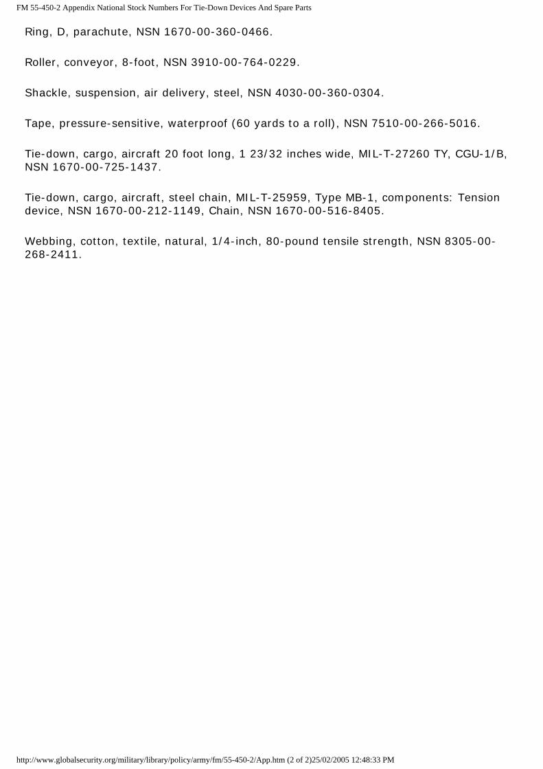
FM 55-450-2 Appendix National Stock Numbers For Tie-Down Devices And Spare Parts
Ring, D, parachute, NSN 1670-00-360-0466.
Roller, conveyor, 8-foot, NSN 3910-00-764-0229.
Shackle, suspension, air delivery, steel, NSN 4030-00-360-0304.
Tape, pressure-sensitive, waterproof (60 yards to a roll), NSN 7510-00-266-5016.
Tie-down, cargo, aircraft 20 foot long, 1 23/32 inches wide, MIL-T-27260 TY, CGU-1/B, NSN 1670-00-725-1437.
Tie-down, cargo, aircraft, steel chain, MIL-T-25959, Type MB-1, components: Tension device, NSN 1670-00-212-1149, Chain, NSN 1670-00-516-8405.
Webbing, cotton, textile, natural, 1/4-inch, 80-pound tensile strength, NSN 8305-00-268-2411.
http://www.globalsecurity.org/military/library/policy/army/fm/55-450-2/App.htm (2 of 2)25/02/2005 12:48:33 PM

FM 55-450-2 Glossary
GLOSSARY
A area
APOD aerial port of debarkation
APOE aerial port of embarkation
cap capacity
CB center of balance
CG center of gravity
CH cargo helicopter
DTO division transportation officer
EHSD effective holding strength of device
FAW front axle weight
FOH front overhang
ft foot
FTBR force to be restrained
fwd forward
G gravity
G3 Assistant Chief of Staff, Operations and Plans
HICHS helicopter internal cargo-handling system
K thousand
http://www.globalsecurity.org/military/library/policy/army/fm/55-450-2/GLOSS.htm (1 of 3)25/02/2005 12:48:54 PM

FM 55-450-2 Glossary
L length
lat latitude
lb pound
long longitude
LZ landing zone
m meter
MACOM major Army command
MCC movement control center
MHE materials-handling equipment
NBC nuclear, biological, chemical
NSN national stock number
pam pamphlet
psf pounds per square foot
psi pounds per square inch
PZ pickup zone
RAW rear axle weight
RD reference datum
RDL reference datum line
ROH rear overhang
RSD rated strength of device
S3 Operations and Training Officer, US Army
SOP standing operating procedure
sq square
http://www.globalsecurity.org/military/library/policy/army/fm/55-450-2/GLOSS.htm (2 of 3)25/02/2005 12:48:54 PM

FM 55-450-2 Glossary
sta station
TRADOC US Army Training and Doctrine Command
UH utility helicopter
W width
WB wheel base
WRM war readiness material
wt weight
http://www.globalsecurity.org/military/library/policy/army/fm/55-450-2/GLOSS.htm (3 of 3)25/02/2005 12:48:54 PM

FM 55-450-2 References
REFERENCES
SOURCES USED
These are the sources quoted or paraphrased in this publication.
AR 310-25, Dictionary of United States Army Terms, 15 October 1983.
AR 310-50, Authorized Abbreviations and Brevity Codes, 15 November 1985.
DA Pam 746-1, Pallets and Storage Aids for Army Use, 28 October 1988.
FM 57-38, Pathfinder Operations, 9 October 1968.
FM 90-4, Air Assault Operations, 16 March 1987.
TB 55-46-1, Standard Characteristics (Dimensions, Weight, and Cube) for Transportability of Military Vehicles and Other Outsize/Overweight Equipment, 1 January 1990.
TM 10-1670-201-23, Organizational and Direct Support Maintenance Manual for General Maintenance of Parachutes and Other Airdrop Equipment, 30 October 1973.
TM 10-1670-240-20, Organizational Maintenance Manual (Including Repair Parts and Special Tools List); Miscellaneous Airdrop Canvas, Webbing, Metal, and Wood Items, 14 April 1970.
TM 38-250, Packaging and Materials Handling: Preparing of Hazardous Materials for Military Air Shipments, 15 January 1988.
TM 55-1520-210-10, Operator's Manual for UH-1H/ V Helicopters, 15 February 1988.
TM 55-1520-217-10-1, Operator's Manual: Army Model CH-54A Helicopters, 8 April 1977.
TM 55-1520-217-10-2, Operator's Manual: Army Model CH-54B Helicopters, 15 April 1977.
TM 55-1520-220-10, Operator's Manual: Army Model UH-1C/M Helicopter, 8
http://www.globalsecurity.org/military/library/policy/army/fm/55-450-2/REF.htm (1 of 3)25/02/2005 12:49:25 PM
FM 55-450-2 References
September 1980.
TM 55-1520-237-10, Operator's Manual: UH-60A and EH-60A Helicopters, 8 January 1988.
TM 55-1520-240-10, Operator's Manual for CH-47D Helicopter, 10 November 1982.
DOCUMENTS NEEDED
These documents must be available to the intended users of this publication.
DA Form 2028, Recommended Changes to Publications and Blank Forms, February 1974.
DA Form 2404, Equipment Inspection and Maintenance Worksheet, April 1979.
READINGS RECOMMENDED
These documents must be available to the intended users of this publication.
STANAG 2101, Principles and Procedures for Establishing Liaison, 31 January 1985.
STANAG 2135, Procedures for Requesting and Providing Logistics Assistance, 12 February 1982.
STANAG 2904, Airmobile Operations, 25 April 1979.
STANAG 2999, Use of Helicopters in Land Operations (ATP- 49), 15 May 1987.
STANAG 3093, NATO Air Transport Request and Answer to Air Transport Request (NARAT and TRANSAR), 29 November 1988.
STANAG 3117, Aircraft Marshaling Signals, 15 October 1985.
STANAG 3345, Forms for Planning Air Movements, 5 February 1988.
STANAG 3465, Safety, Emergency and Signalling Procedures for Military Air Movement Fixed-Wing Aircraft, 19 November 1973.
STANAG 3542, Technical Criteria for the Transport of Cargo by Helicopter, 27 July 1981.
STANAG 3543, Air Transport Cargo/Passenger Handling Systems-Request for Information, 21 October 1986.
STANAG 3631, Wartime Air Movement Priority System for NATO Countries, 27 October 1983.
http://www.globalsecurity.org/military/library/policy/army/fm/55-450-2/REF.htm (2 of 3)25/02/2005 12:49:25 PM

FM 55-450-2 References
STANAG 3854, Policies and Procedures Governing the Air Transportation of Dangerous Cargo, 15 February 1988.
http://www.globalsecurity.org/military/library/policy/army/fm/55-450-2/REF.htm (3 of 3)25/02/2005 12:49:25 PM