fm transceiver ft-1802m - rigpix database - main · dcs operation ... manual dtmf tone generation...
TRANSCRIPT

FM TRANSCEIVER
FT-1802M
OPERATING MANUAL
VERTEX STANDARD CO., LTD.4-8-8 Nakameguro, Meguro-Ku, Tokyo 153-8644, Japan
VERTEX STANDARDUS Headquarters10900 Walker Street, Cypress, CA 90630, U.S.A.
YAESU EUROPE B.V.P.O. Box 75525, 1118 ZN Schiphol, The Netherlands
YAESU UK LTD.Unit 12, Sun Valley Business Park, Winnall CloseWinchester, Hampshire, SO23 0LB, U.K.
VERTEX STANDARD HK LTD.Unit 5, 20/F., Seaview Centre, 139-141 Hoi Bun Road,Kwun Tong, Kowloon, Hong Kong
Contents
Introduction ...................................................... 1
Specifications .................................................... 2
Accessories & Options ..................................... 3
Supplied Accessories ..................................... 3
Optional Accessories ...................................... 3
Installation ........................................................ 4
Preliminary Inspection ................................... 4
Installation Tips .............................................. 4
Safety Information ......................................... 5
Antenna Considerations ................................. 6
Mobile Installation ......................................... 7
Mobile Power Connections ........................ 8
Mobile Speakers ........................................ 8
Base Station Installation ................................ 9
AC Power Supplies .................................... 9
Front Panel Controls & Switches ................. 10
Microphone Switches ..................................... 12
Rear Panel Connectors .................................. 13
Basic Operation .............................................. 14
Turning the Transceiver On and Off ........... 14
Adjusting the Audio Volume Level ............. 14
Adjusting the Squelch Setting ..................... 14
Frequency Navigation .................................. 15
1) Tuning Dial ......................................... 15
2) Direct Keypad Frequency Entry .......... 15
3) Scanning .............................................. 15
Transmission ................................................ 16
Changing the Transmitter Power Level ... 16
Advanced Operation ...................................... 17
Weather Broadcast Reception ...................... 17
Lock Feature ................................................. 18
Keyboard Beeper .......................................... 18
Channel Step Selection ................................ 19
Display Brightness ....................................... 19
RF Squelch ................................................... 20
Repeater Operation ...................................... 21
Standard Repeater Shift ........................... 21
Automatic Repeater Shift (ARS) ............. 22
Separate Transmit Frequency Memory
(“Odd Splits”) ...................................... 23
CTCSS/DCS/EPCS Operation ..................... 24
CTCSS Operation .................................... 24
DCS Operation ......................................... 25
Tone Search Scanning ............................. 26
EPCS Operation ....................................... 27
CTCSS/DCS/EPCS Bell Paging .............. 29
Split Tone Operation ............................... 27
DTMF Operation .......................................... 32
Manual DTMF Tone Generation ............. 32
DTMF Autodialer .................................... 32
Memory Operation ........................................ 34
Memory Storage ........................................... 34
Memory Recall ............................................. 35
Labeling Memories ...................................... 36
Memory Tuning ........................................... 37
Masking Memories ...................................... 37
Memory Bank Operation ............................. 38
Assigning Memories to a Memory Bank . 38
Memory Bank Recall ............................... 38
Removing Memories
from a Memory Bank .......................... 39
Changing a Memory Bank’s Name ......... 39
HOME Channel Memory ............................. 40
Memory Only Mode ..................................... 41
Scanning .......................................................... 42
Basic Scanner Operation .............................. 42
Scan-Resume Option ................................... 43
Memory Skip Scanning ............................... 44
Preferential Memory Scan ........................... 45
Memory Bank Link Scan ............................. 46
Programmable Band-Scan Limits ................ 47
Priority Channel Scanning (Dual Watch) .... 48
Priority Revert Mode ............................... 48
Weather Alert Scan ...................................... 49
Band Edge Beeper ........................................ 49
Smart Search Operation ................................ 50
Internet Connection Feature ......................... 52
SRG Mode .................................................... 52
FRG Mode .................................................... 52
ARTS™ ........................................................... 55
Basic ARTS™ Setup and Operation ........... 55
ARTS™ Polling Time Options .................... 56
ARTS™ Alert Beep Options ....................... 56
CW Identifier Setup ..................................... 57
CW Training Feature .................................... 58
Packet Operation ............................................ 59
Miscellaneous Settings ................................... 60
Password ...................................................... 60
Time-Out Timer ........................................... 61
Automatic Power-Off ................................... 61
Busy Channel Lock-Out .............................. 62
Programming the Key Assignments ............ 63
FM Bandwidth & TX Deviation Level ........ 64
MIC Gain Setting ......................................... 64
DCS Code Inversion .................................... 65
Reset Procedure .............................................. 66
Microprocessor Resetting ............................ 66
Set Mode Resetting ...................................... 66
Cloning ............................................................ 67
“Set” (Menu) Mode ........................................ 68
1FT-1802M OPERATING MANUAL
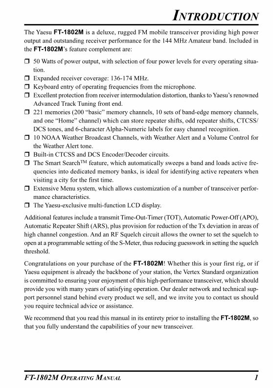
The Yaesu FT-1802M is a deluxe, rugged FM mobile transceiver providing high power
output and outstanding receiver performance for the 144 MHz Amateur band. Included in
the FT-1802M’s feature complement are:
� 50 Watts of power output, with selection of four power levels for every operating situa-
tion.
� Expanded receiver coverage: 136-174 MHz.
� Keyboard entry of operating frequencies from the microphone.
� Excellent protection from receiver intermodulation distortion, thanks to Yaesu’s renowned
Advanced Track Tuning front end.
� 221 memories (200 “basic” memory channels, 10 sets of band-edge memory channels,
and one “Home” channel) which can store repeater shifts, odd repeater shifts, CTCSS/
DCS tones, and 6-character Alpha-Numeric labels for easy channel recognition.
� 10 NOAA Weather Broadcast Channels, with Weather Alert and a Volume Control for
the Weather Alert tone.
� Built-in CTCSS and DCS Encoder/Decoder circuits.
� The Smart SearchTM feature, which automatically sweeps a band and loads active fre-
quencies into dedicated memory banks, is ideal for identifying active repeaters when
visiting a city for the first time.
� Extensive Menu system, which allows customization of a number of transceiver perfor-
mance characteristics.
� The Yaesu-exclusive multi-function LCD display.
Additional features include a transmit Time-Out-Timer (TOT), Automatic Power-Off (APO),
Automatic Repeater Shift (ARS), plus provision for reduction of the Tx deviation in areas of
high channel congestion. And an RF Squelch circuit allows the owner to set the squelch to
open at a programmable setting of the S-Meter, thus reducing guesswork in setting the squelch
threshold.
Congratulations on your purchase of the FT-1802M! Whether this is your first rig, or if
Yaesu equipment is already the backbone of your station, the Vertex Standard organization
is committed to ensuring your enjoyment of this high-performance transceiver, which should
provide you with many years of satisfying operation. Our dealer network and technical sup-
port personnel stand behind every product we sell, and we invite you to contact us should
you require technical advice or assistance.
We recommend that you read this manual in its entirety prior to installing the FT-1802M, so
that you fully understand the capabilities of your new transceiver.
INTRODUCTION
2 FT-1802M OPERATING MANUAL
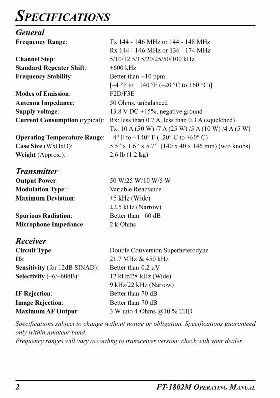
General
Frequency Range: Tx 144 - 146 MHz or 144 - 148 MHz
Rx 144 - 146 MHz or 136 - 174 MHz
Channel Step: 5/10/12.5/15/20/25/50/100 kHz
Standard Repeater Shift: ±600 kHz
Frequency Stability: Better than ±10 ppm
[–4 °F to +140 °F (–20 °C to +60 °C)]
Modes of Emission: F2D/F3E
Antenna Impedance: 50 Ohms, unbalanced
Supply voltage: 13.8 V DC ±15%, negative ground
Current Consumption (typical): Rx: less than 0.7 A, less than 0.3 A (squelched)
Tx: 10 A (50 W) /7 A (25 W) /5 A (10 W) /4 A (5 W)
Operating Temperature Range: –4° F to +140° F (–20° C to +60° C)
Case Size (WxHxD): 5.5” x 1.6” x 5.7” (140 x 40 x 146 mm) (w/o knobs)
Weight (Approx.): 2.6 lb (1.2 kg)
Transmitter
Output Power: 50 W/25 W/10 W/5 W
Modulation Type: Variable Reactance
Maximum Deviation: ±5 kHz (Wide)
±2.5 kHz (Narrow)
Spurious Radiation: Better than –60 dB
Microphone Impedance: 2 k-Ohms
Receiver
Circuit Type: Double Conversion Superheterodyne
Ifs: 21.7 MHz & 450 kHz
Sensitivity (for 12dB SINAD): Better than 0.2 µV
Selectivity (–6/–60dB): 12 kHz/28 kHz (Wide)
9 kHz/22 kHz (Narrow)
IF Rejection: Better than 70 dB
Image Rejection: Better than 70 dB
Maximum AF Output: 3 W into 4 Ohms @10 % THD
Specifications subject to change without notice or obligation. Specifications guaranteed
only within Amateur band.
Frequency ranges will vary according to transceiver version; check with your dealer.
SPECIFICATIONS
3FT-1802M OPERATING MANUAL
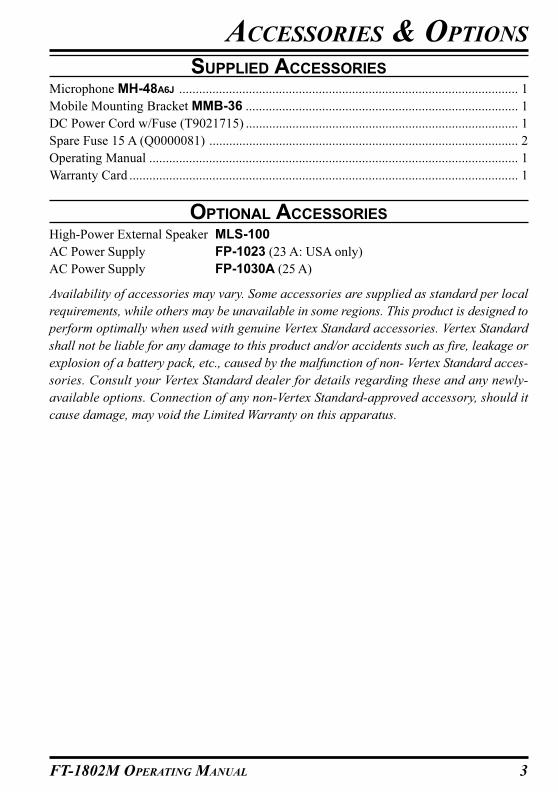
SUPPLIED ACCESSORIES
Microphone MH-48A6J ...................................................................................................... 1
Mobile Mounting Bracket MMB-36 .................................................................................. 1
DC Power Cord w/Fuse (T9021715) .................................................................................. 1
Spare Fuse 15 A (Q0000081) ............................................................................................. 2
Operating Manual ............................................................................................................... 1
Warranty Card ..................................................................................................................... 1
OPTIONAL ACCESSORIES
High-Power External Speaker MLS-100
AC Power Supply FP-1023 (23 A: USA only)
AC Power Supply FP-1030A (25 A)
Availability of accessories may vary. Some accessories are supplied as standard per local
requirements, while others may be unavailable in some regions. This product is designed to
perform optimally when used with genuine Vertex Standard accessories. Vertex Standard
shall not be liable for any damage to this product and/or accidents such as fire, leakage or
explosion of a battery pack, etc., caused by the malfunction of non- Vertex Standard acces-
sories. Consult your Vertex Standard dealer for details regarding these and any newly-
available options. Connection of any non-Vertex Standard-approved accessory, should it
cause damage, may void the Limited Warranty on this apparatus.
ACCESSORIES & OPTIONS

4 FT-1802M OPERATING MANUAL
This chapter describes the installation procedure for integrating the FT-1802M into a typi-
cal amateur radio station. It is presumed that you possess technical knowledge and concep-
tual understanding consistent with your status as a licensed radio amateur. Please take some
extra time to make certain that the important safety and technical requirements detailed in
this chapter are followed closely.
PRELIMINARY INSPECTION
Inspect the transceiver visually immediately upon opening the packing carton. Confirm that
all controls and switches work freely, and inspect the cabinet for any damage. Gently shake
the transceiver to verify that no internal components have been shaken loose due to rough
handling during shipping.
If any evidence of damage is discovered, document it thoroughly and contact the shipping
company (or your local dealer, if the unit was purchased over-the-counter) so as to get
instructions regarding the prompt resolution of the damage situation. Be certain to save the
shipping carton, especially if there are any punctures or other evidence of damage incurred
during shipping; if it is necessary to return the unit for service or replacement, use the origi-
nal packing materials but put the entire package inside another packing carton, so as to
preserve the evidence of shipping damage for insurance purposes.
INSTALLATION TIPS
To ensure long life of the components, be certain to provide adequate ventilation around the
cabinet of the FT-1802M.
Do not install the transceiver on top of another heat-generating device (such as a power
supply or amplifier), and do not place equipment, books, or papers on top of the FT-1802M.
Avoid heating vents and window locations that could expose the transceiver to excessive
direct sunlight, especially in hot climates. The FT-1802M should not be used in an environ-
ment where the ambient temperature exceeds +140 °F (+60 °C).
INSTALLATION
5FT-1802M OPERATING MANUAL
INSTALLATION
SAFETY INFORMATION
The FT-1802M is an electrical apparatus, as well as a generator of RF (Radio Frequency)
energy, and you should exercise all safety precautions as are appropriate for this type of
device. These safety tips apply to any device installed in a well-designed amateur radio
station.
Never allow unsupervised children to play in the vicinity of your transceiver or an-
tenna installation.
Be certain to wrap any wire or cable splices thoroughly with insulating electrical
tape, to prevent short circuits.
Do not route cables or wires through door jambs or other locations where, through
wear and tear, they may become frayed and shorted to ground or to each other.
Do not stand in front of a directional antenna while you are transmitting into that
antenna. Do not install a directional antenna in any location where humans or pets
may be walking in the main directional lobe of the antenna’s radiation pattern.
In mobile installations, it is preferable to mount your antenna on top of the roof of the
vehicle, if feasible, so as to utilize the car body as a counterpoise for the antenna and
raise the radiation pattern as far away from passengers as possible.
During vehicular operation when stopped (in a parking lot, for example), make it a
practice to switch to Low power if there are people walking nearby.
Never wear dual-earmuff headphones while driving a vehicle.
Do not attempt to drive your vehicle while making a telephone call on an autopatch
using the DTMF microphone. Pull over to the side of the road, whether dialing manu-
ally or using the auto-dial feature.

6 FT-1802M OPERATING MANUAL
ANTENNA CONSIDERATION
The FT-1802M is designed for use with antennas presenting an impedance of near 50 Ohms
at all operating frequencies. The antenna (or a 50 Ohm dummy load) should be connected
whenever the transceiver is turned on, to avoid damage that could otherwise result if trans-
mission occurs accidentally without an antenna.
Ensure that your antenna is designed to handle 50 Watts of transmitter power. Some mag-
netic-mount mobile antennas, designed for use with hand-held transceivers, may not be
capable of withstanding this power level. Consult the antenna manufacturer’s specification
sheet for details.
Most all FM work is performed using vertical polarization. When installing a directional
antenna such as a Yagi or Cubical Quad, be certain to orient it so as to produce vertical
polarization, unless you are engaged in a special operating situation where horizontal polar-
ization is used. In the case of a Yagi antenna, orient the elements vertically for vertical
polarization; for a Cubical Quad, the feedpoint should be at the center of one of the vertical
sides of the driven element (or at a side corner, in the case of a diamond-shaped “Delta
Loop”).
Excellent reference texts and computer software are available for the design and optimiza-
tion of VHF antennas. Your dealer should be able to assist you with all aspects of your
antenna installation requirements.
Use high-quality 50 Ohm coaxial cable for the lead-in to your FT-1802M transceiver. All
efforts at providing an efficient antenna system will be wasted if poor quality, lossy coaxial
cable is used. Losses in coaxial lines increase as the frequency increases, so an 8-meter-long
(25’ coaxial line with 1/2 dB of loss at 29 MHz may have a loss of 1.8 dB or more at 146
MHz; choose your coaxial cable carefully based on the installation location (mobile vs.
base) and the overall length of the cable required (for very short runs of cable in a mobile
installation, the smaller, more flexible cable types may be acceptable).
For reference, the chart at the right shows ap-
proximate loss figures for typically-available
coaxial cables frequently used in VHF instal-
lations.
In outdoor installations, be certain to weather-
proof all connectors thoroughly, as water en-
tering a coaxial cable will cause losses to es-
calate rapidly, thus diminishing your commu-
nications effectiveness. The use of the shortest
possible length of the highest quality coaxial
cable that fits within your budget will ensure the best performance from your FT-1802M.
INSTALLATION
CABLE TYPE
RG-58ARG-58 Foam
RG-213RG-8 FoamBelden 9913
Times Microwave LMR-4007/8” “Hardline”
LOSS: 144 MHZ
6.54.73.02.01.51.50.7
Loss in dB per 30 m (100 feet) for
Selected 50-Ohm Coaxial Cables
(Assumes 50-ohm Input/Output Terminations)
Loss figures are approximate; consult cable manu-facturers’ catalogs for complete specifications.
7FT-1802M OPERATING MANUAL
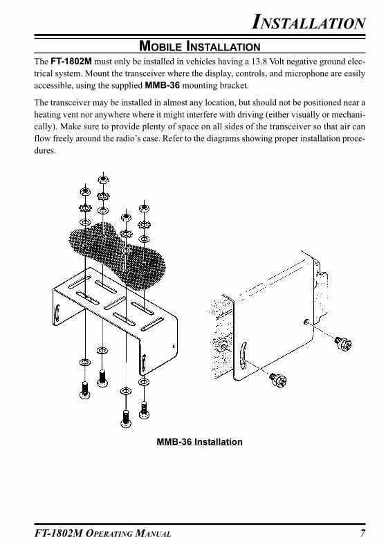
MOBILE INSTALLATION
The FT-1802M must only be installed in vehicles having a 13.8 Volt negative ground elec-
trical system. Mount the transceiver where the display, controls, and microphone are easily
accessible, using the supplied MMB-36 mounting bracket.
The transceiver may be installed in almost any location, but should not be positioned near a
heating vent nor anywhere where it might interfere with driving (either visually or mechani-
cally). Make sure to provide plenty of space on all sides of the transceiver so that air can
flow freely around the radio’s case. Refer to the diagrams showing proper installation proce-
dures.
INSTALLATION
MMB-36 Installation

8 FT-1802M OPERATING MANUAL
Mobile Power ConnectionsTo minimize voltage drop and avoid blowing the vehicle’s fuses, connect the supplied DC
power cable directly to the battery terminals. Do not attempt to defeat or bypass the DC
cable’s fuse - it is there to protect you, your transceiver, and your vehicle’s electrical system.
Warning!
Never apply AC power to the power cable of the FT-1802M, nor DC voltage greater
than 15.8 Volts. When replacing the fuse, only use a 15-A fuse. Failure to observe
these safety precautions will void the Limited Warranty on this product.
� Before connecting the transceiver, check the voltage at the battery terminals while rev-
ving the engine. If the voltage exceeds 15 Volts, adjust the vehicle’s voltage regulator
before proceeding with installation.
� Connect the RED power cable lead to the POSITIVE (+) battery terminal, and the BLACK
power cable lead to the NEGATIVE (–) terminal. If you need to extend the power cable,
use #12 AWG or larger insulated, stranded copper wire. Solder the splice connections
carefully, and wrap the connections thoroughly with insulating electrical tape.
� Before connecting the cable to the transceiver, verify the voltage and polarity of the
voltage at the transceiver end of the DC cable using a DC voltmeter. Now connect the
transceiver to the DC cable.
INSTALLATION
Mobile SpeakersThe optional MLS-100 External Speaker includes its own swivel-type mounting bracket,
and is available from your Yaesu dealer.
Other external speakers may be used with the FT-1802M, if they present the specified 4-Ohm
impedance and are capable of handling the 3 Watts of audio output supplied by the FT-1802M.
MOBILE INSTALLATION
Cabin Engine Room� �
FT-1802M
BatteryRED: Positive (+)BLACK: Negative (–)

9FT-1802M OPERATING MANUAL
INSTALLATION
BASE STATION INSTALLATION
The FT-1802M is ideal for base station use as well as in mobile installations. The FT-
1802M is specifically designed to integrate into your station easily, using the information to
follow as a reference.
AC Power SuppliesOperation of the FT-1802M from an AC line requires a power source capable of providing
at least 10 Amps continuously at 13.8 Volts DC. The FP-1023 and FP-1030A AC Power
Supplies are available from your Yaesu dealer to satisfy these requirements. Other well-
regulated power supplies may be used, as well, if they meet the above voltage and current
specifications.
Use the DC power cable supplied with your transceiver for making power connections to the
power supply. Connect the RED power cable lead to the POSITIVE (+) power supply
terminal, and connect the BLACK power cable lead to the NEGATIVE (–) power supply
terminal.
10 FT-1802M OPERATING MANUAL
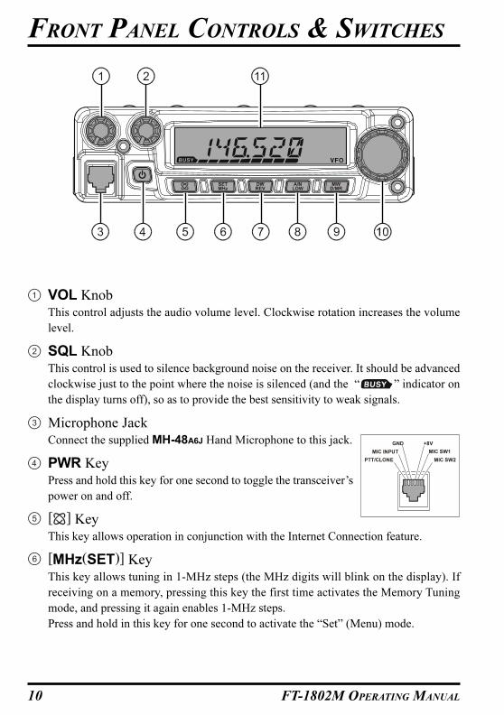
VOL KnobThis control adjusts the audio volume level. Clockwise rotation increases the volume
level.
SQL KnobThis control is used to silence background noise on the receiver. It should be advanced
clockwise just to the point where the noise is silenced (and the “ ” indicator on
the display turns off), so as to provide the best sensitivity to weak signals.
Microphone JackConnect the supplied MH-48A6J Hand Microphone to this jack.
PWR KeyPress and hold this key for one second to toggle the transceiver’s
power on and off.
[ ] KeyThis key allows operation in conjunction with the Internet Connection feature.
[MHz(SET)] KeyThis key allows tuning in 1-MHz steps (the MHz digits will blink on the display). If
receiving on a memory, pressing this key the first time activates the Memory Tuning
mode, and pressing it again enables 1-MHz steps.
Press and hold in this key for one second to activate the “Set” (Menu) mode.
FRONT PANEL CONTROLS & SWITCHES
MIC SW2
MIC SW1
GND +8V
MIC INPUT
PTT/CLONE
11FT-1802M OPERATING MANUAL
FRONT PANEL CONTROLS & SWITCHES
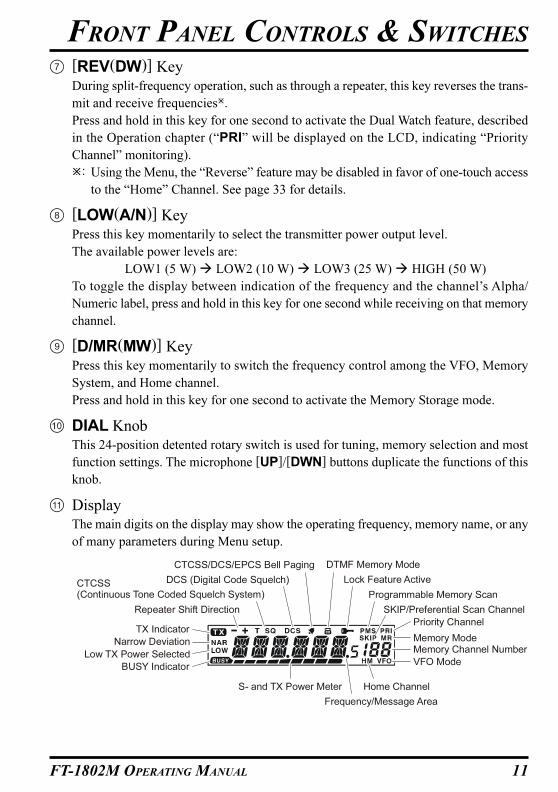
[REV(DW)] KeyDuring split-frequency operation, such as through a repeater, this key reverses the trans-
mit and receive frequencies�.
Press and hold in this key for one second to activate the Dual Watch feature, described
in the Operation chapter (“PRI” will be displayed on the LCD, indicating “Priority
Channel” monitoring).
�: Using the Menu, the “Reverse” feature may be disabled in favor of one-touch access
to the “Home” Channel. See page 33 for details.
[LOW(A/N)] KeyPress this key momentarily to select the transmitter power output level.
The available power levels are:
LOW1 (5 W) � LOW2 (10 W) � LOW3 (25 W) � HIGH (50 W)
To toggle the display between indication of the frequency and the channel’s Alpha/
Numeric label, press and hold in this key for one second while receiving on that memory
channel.
[D/MR(MW)] KeyPress this key momentarily to switch the frequency control among the VFO, Memory
System, and Home channel.
Press and hold in this key for one second to activate the Memory Storage mode.
DIAL KnobThis 24-position detented rotary switch is used for tuning, memory selection and most
function settings. The microphone [UP]/[DWN] buttons duplicate the functions of this
knob.
DisplayThe main digits on the display may show the operating frequency, memory name, or any
of many parameters during Menu setup.
CTCSS(Continuous Tone Coded Squelch System)
DCS (Digital Code Squelch)
DTMF Memory ModeCTCSS/DCS/EPCS Bell Paging
Lock Feature Active
Programmable Memory Scan
Priority Channel
Memory ModeMemory Channel Number
VFO Mode
Home Channel
Frequency/Message Area
SKIP/Preferential Scan ChannelRepeater Shift Direction
Low TX Power Selected
TX Indicator
BUSY Indicator
Narrow Deviation
S- and TX Power Meter

12 FT-1802M OPERATING MANUAL
PTT SwitchPress this switch to transmit, and release it
to receive.
KeypadThese 16 keys generate DTMF tones during
transmission.
In the receive mode, these 16 keys can be
used for direct frequency entry and/or direct
numeric recall of the Memory channels.
The [A], [B], [C], and [D] keys, on receive,
replicate the functions of the front panel keys
([MHz(SET)], [REV(DW)], [LOW(A/N)],
and [D/MR(MW)]). See the previous discus-
sion.
[P1]/[P2]/[P3]/[P4] ButtonsThese four keys are user programmable, al-
lowing quick access to features used often.
The default functions are described below.
[P1] button (SQL OFF)
Press this button to disable the noise and tone squelch systems.
[P2] button (S SRCH)
Press this button to activate the Smart Search feature.
[P3] button (C SRCH)
Press this button to activate the Tone Search feature.
[P4] button (WX CH/T.CALL)
In the USA version, pressing this button recalls the “Weather” broadcast channel bank. In
the EXP version, pressing this button activates T.CALL (1750 Hz) for repeater access.
You can reprogram the [P1], [P2], [P3], and [P4] buttons for other functions, if de-
sired. See page 63 for details.
LAMP SwitchThis switch illuminates the Microphone’s keypad.
LOCK SwitchThis switch locks out the Microphone’s buttons (except for the keypad and PTT switch).
[UP]/[DWN] ButtonPress (or hold in) either of these buttons to tune (or scan up or down) the operating
frequency or through the memory channels. In many ways, these buttons emulate the
function of the (rotary) DIAL knob.
MICROPHONE SWITCHES
DTMF MICROPHONE
MH-48
13FT-1802M OPERATING MANUAL
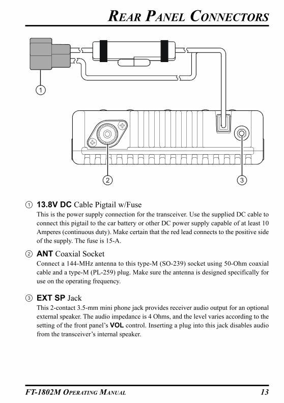
13.8V DC Cable Pigtail w/FuseThis is the power supply connection for the transceiver. Use the supplied DC cable to
connect this pigtail to the car battery or other DC power supply capable of at least 10
Amperes (continuous duty). Make certain that the red lead connects to the positive side
of the supply. The fuse is 15-A.
ANT Coaxial SocketConnect a 144-MHz antenna to this type-M (SO-239) socket using 50-Ohm coaxial
cable and a type-M (PL-259) plug. Make sure the antenna is designed specifically for
use on the operating frequency.
EXT SP JackThis 2-contact 3.5-mm mini phone jack provides receiver audio output for an optional
external speaker. The audio impedance is 4 Ohms, and the level varies according to the
setting of the front panel’s VOL control. Inserting a plug into this jack disables audio
from the transceiver’s internal speaker.
REAR PANEL CONNECTORS
14 FT-1802M OPERATING MANUAL
Hi! I’m R. F. Radio, and I’ll be helping you along as you learn the many features
of the FT-1802M. I know you’re anxious to get on the air, but I encourage you to
read the “Basic Operation” section of this manual as thoroughly as possible, so you’ll get
the most out of this fantastic new transceiver. Now. . .let’s get operating!
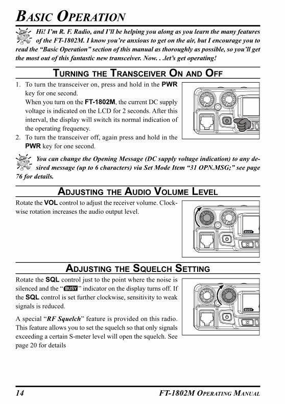
TURNING THE TRANSCEIVER ON AND OFF
1. To turn the transceiver on, press and hold in the PWR
key for one second.
When you turn on the FT-1802M, the current DC supply
voltage is indicated on the LCD for 2 seconds. After this
interval, the display will switch its normal indication of
the operating frequency.
2. To turn the transceiver off, again press and hold in the
PWR key for one second.
You can change the Opening Message (DC supply voltage indication) to any de-
sired message (up to 6 characters) via Set Mode Item “31 OPN.MSG;” see page
76 for details.
ADJUSTING THE AUDIO VOLUME LEVEL
Rotate the VOL control to adjust the receiver volume. Clock-
wise rotation increases the audio output level.
ADJUSTING THE SQUELCH SETTING
Rotate the SQL control just to the point where the noise is
silenced and the “ ” indicator on the display turns off. If
the SQL control is set further clockwise, sensitivity to weak
signals is reduced.
A special “RF Squelch” feature is provided on this radio.
This feature allows you to set the squelch so that only signals
exceeding a certain S-meter level will open the squelch. See
page 20 for details
BASIC OPERATION

15FT-1802M OPERATING MANUAL
BASIC OPERATION
FREQUENCY NAVIGATION
1) Tuning DialRotating the DIAL knob allows tuning in the pre-programmed steps. Clockwise rotation of the
DIAL knob causes the FT-1802M to be tuned toward a higher frequency, while counter-clock-
wise rotation will lower the operating frequency.
Press the [MHz(SET)] key momentarily, then rotate the DIAL knob, to change the frequency
steps to 1 MHz per step. This feature is extremely useful for making rapid frequency excursions
over the wide tuning range of the FT-1802M. Instead of pressing the [MHz(SET)] button, you
may also press the [A] key on the Microphone’s keypad to engage tuning in 1 MHz steps.
2) Direct Keypad Frequency EntryThe keypad of the MH-48A6J DTMF Microphone may be used for direct entry of the oper-
ating frequency.
To enter a frequency from the MH-48A6J keypad, just press the numbered digits in the
proper sequence. There is no “decimal point” key on the MH-48A6J keypad. However, there
is a short-cut for frequencies ending in zero: press the [#] key after the last non-zero digit.
Examples: To enter 146.520 MHz, press [1] � [4] � [6] � [5] � [2] � [0]
To enter 146.000 MHz, press [1] � [4] � [6] � [#]
If you cannot get the radio to accept the frequency entry, it is possible that the
channel steps are set to an incompatible value (e.g. if you have 25 kHz steps set,
you cannot set a frequency of 146.520 MHz). See page 19 to learn how to change the
channel step size.
3) ScanningFrom the VFO mode, press the microphone’s [UP]/[DWN] keys momentarily to initiate
scanning toward a higher- or lower frequency, respectively. The FT-1802M will stop when
it receives a signal strong enough to break through the squelch threshold. The FT-1802M
will then hold on that frequency according to the setting of the “Resume” mode (Menu “41
SCAN)”; see page 43).
If you wish to reverse the direction of the scan (i.e. toward a lower frequency, instead of a
higher frequency), just rotate the DIAL knob one click in the counter-clockwise direction
while the FT-1802M is scanning. The scanning direction will be reversed. To revert to
scanning toward a higher frequency once more, rotate the DIAL knob one click clockwise.
Press the [UP]/[DWN] keys again to cancel scanning. You may also press the PTT button
momentarily; scanning will stop, but you will not transmit until you release the PTT button,
and press it again.
If you have enabled the “Severe Weather Alert” feature, you will occasionally no-
tice “WX” channels interspersed with the regular channels you are scanning. This
is normal, because your radio is constantly monitoring for weather alerts. See page 17.

16 FT-1802M OPERATING MANUAL
TRANSMISSION
To transmit, simply close the PTT (Push To Talk) switch on the microphone when the fre-
quency is clear. Hold the microphone approximately 1” (25 mm) from your mouth, and
speak into the microphone in a normal voice level. When your transmission is complete,
release the PTT switch; the transceiver will revert to the receive mode.
During transmission, the “ ” indicator will appear at the upper left corner on the display.
Changing the Transmitter Power Level
You can select from among a total of four transmit power levels on your FT-1802M.
To change the power level, press the [LOW(A/N)] key (or the microphone’s [C] key to
select one of four power settings. These power levels will be stored, in memory registers, at
the time of memory storage (see page 34 for details on Memory operation).
During transmission, the Bar Graph will deflect in the display, according to the power out-
put selected.
BASIC OPERATION
Low 1 (5 watts)
Low 2 (10 watts)
Low 3 (25 watts)
HIGH (50 watts)

17FT-1802M OPERATING MANUAL
WEATHER BROADCAST RECEPTION (USA VERSION)The FT-1802M includes a unique feature which allows reception of weather broadcasts in
the 160-MHz frequency range. Ten standard Weather Broadcast channels are pre-loaded
into a special memory bank.
To listen to a Weather Broadcast Channel:
1. Press the Microphone’s [P4] button to recall the Weather
Broadcast channels.
2. Turn the DIAL knob to select the desired Weather Broadcast channel.
3. If you wish to check the other channels for activity
by scanning, just press the Microphone’s PTT
switch.
4. To exit to normal operation, press the [P4] button
again. Operation will return to the VFO or Memory
channel you were operating on before you began Weather Broadcast operation.
The [P4] key, one of the programmable keys, is assigned (default setting) as the
“WX Broadcast” one-touch access key. Please note that if you change/assign an-
other function to the [P4] key, one-touch access to the WX channel will be unavailable.
Severe Weather Alert Feature
In the event of extreme weather disturbances, such as storms and hurricanes, NOAA (the
National Oceanic and Atmospheric Administration) sends a weather alert accompanied by a
1050 Hz tone and subsequent weather report on one of the NOAA weather channels. You
may enable this feature via Menu Item “57 WX ALT,” if desired. See page 49 for details.
When scanning the band or the “regular” memories, with the Severe Weather Alert feature
engaged, you will notice that the FT-1802M will break over to the Weather Channel bank
every five seconds, performing a quick scan of those channels in search for the 1050 Hz
alert tone. If the alert tone is received, operation will lock on the weather broadcast station
issuing the alert; otherwise, the radio will revert to the VFO or memory scan session in
progress without interruption.
When the alert tone is received, press the PTT button momentarily to disable the alarm, and
the Severe Weather message will now be audible from the speaker.
ADVANCED OPERATION
CH
01
02
03
04
05
CH
06
07
08
09
10
FREQUENCY
162.550 MHz
162.400 MHz
162.475 MHz
162.425 MHz
162.450 MHz
FREQUENCY
162.500 MHz
162.525 MHz
161.650 MHz
161.775 MHz
163.275 MHz

18 FT-1802M OPERATING MANUAL
LOCK FEATURE
To order to prevent accidental frequency change or inadvertent transmission, various as-
pects of the FT-1802M’s keys and knob may be locked out.
To lock out some or all of the keys, use the “Set” (Menu) mode, described below:
1. Press and hold in the [MHz(SET)] key for one second, then
rotate the DIAL knob to select “26 LOCK.”
2. Press the [MHz(SET)] key, then rotate the DIAL knob to
select the desired lockout combination.
KEY: Just the front panel keys are locked out.
DIAL: Just the front panel DIAL knob is locked out.
K+D: Both the keys and DIAL knob are locked out.
PTT: The PTT switch is locked (TX not possible).
K+P: Both keys and PTT switch are locked out.
D+P: Both DIAL knob and PTT switch are locked out.
ALL: All of the above are locked out.
OFF: The Lock feature is disabled.
3. Press and hold in the [MHz(SET)] key for one second to save your new setting and exit
to normal operation.
When the Lock feature is activated, the “ ” icon will appear
on the LCD.
To disable the Lock feature, repeat the above process, selecting “OFF” in step 2 above.
KEYBOARD BEEPER
A key/button beeper provides useful audible feedback whenever a key/button is pressed. If
you want to turn the beeper off (or back on again):
1. Press and hold in the [MHz(SET)] key for one second, then
rotate the DIAL knob to select “6 BEEP.”
2. Press the [MHz(SET)] key, then rotate the DIAL knob to
set the display to “OFF.”
3. Press and hold in the [MHz(SET)] key for one second to save your new setting and exit
to normal operation.
4. To turn the beep back on again, select “KEY” or “KY+SCN (factory default)” in step 4
above.
KEY: The beeper sounds when you press the keypad.
KY+SCN: The beeper sounds when you press the keypad, or when the scanner stops.
ADVANCED OPERATION
19FT-1802M OPERATING MANUAL
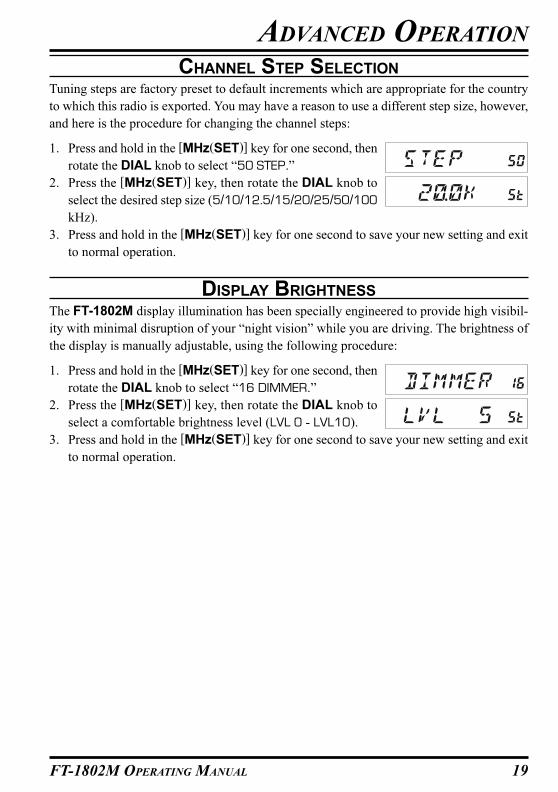
CHANNEL STEP SELECTION
Tuning steps are factory preset to default increments which are appropriate for the country
to which this radio is exported. You may have a reason to use a different step size, however,
and here is the procedure for changing the channel steps:
1. Press and hold in the [MHz(SET)] key for one second, then
rotate the DIAL knob to select “50 STEP.”
2. Press the [MHz(SET)] key, then rotate the DIAL knob to
select the desired step size (5/10/12.5/15/20/25/50/100
kHz).
3. Press and hold in the [MHz(SET)] key for one second to save your new setting and exit
to normal operation.
DISPLAY BRIGHTNESS
The FT-1802M display illumination has been specially engineered to provide high visibil-
ity with minimal disruption of your “night vision” while you are driving. The brightness of
the display is manually adjustable, using the following procedure:
1. Press and hold in the [MHz(SET)] key for one second, then
rotate the DIAL knob to select “16 DIMMER.”
2. Press the [MHz(SET)] key, then rotate the DIAL knob to
select a comfortable brightness level (LVL 0 - LVL10).
3. Press and hold in the [MHz(SET)] key for one second to save your new setting and exit
to normal operation.
ADVANCED OPERATION
20 FT-1802M OPERATING MANUAL
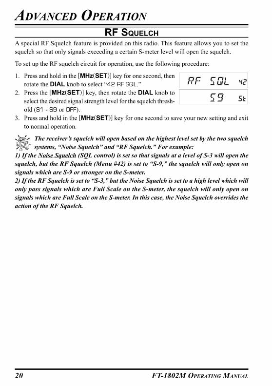
RF SQUELCH
A special RF Squelch feature is provided on this radio. This feature allows you to set the
squelch so that only signals exceeding a certain S-meter level will open the squelch.
To set up the RF squelch circuit for operation, use the following procedure:
1. Press and hold in the [MHz(SET)] key for one second, then
rotate the DIAL knob to select “42 RF SQL.”
2. Press the [MHz(SET)] key, then rotate the DIAL knob to
select the desired signal strength level for the squelch thresh-
old (S1 - S9 or OFF).
3. Press and hold in the [MHz(SET)] key for one second to save your new setting and exit
to normal operation.
The receiver’s squelch will open based on the highest level set by the two squelch
systems, “Noise Squelch” and “RF Squelch.” For example:
1) If the Noise Squelch (SQL control) is set so that signals at a level of S-3 will open the
squelch, but the RF Squelch (Menu #42) is set to “S-9,” the squelch will only open on
signals which are S-9 or stronger on the S-meter.
2) If the RF Squelch is set to “S-3,” but the Noise Squelch is set to a high level which will
only pass signals which are Full Scale on the S-meter, the squelch will only open on
signals which are Full Scale on the S-meter. In this case, the Noise Squelch overrides the
action of the RF Squelch.
ADVANCED OPERATION
21FT-1802M OPERATING MANUAL
REPEATER OPERATION
The FT-1802M includes a host of convenience features which makes operation on amateur
repeaters both efficient and enjoyable.
This transceiver offers three methods of setting up split-frequency operation on repeaters:
� Manual selection of preset repeater shifts (Standard Repeater Shift);
� Automatic Repeater Shift (ARS), providing automatic activation of repeater shifts
while operating within designated repeater frequency subbands; and
� Independently stored transmit and receive frequencies (typically not corresponding
to established repeater frequency shifts).
STANDARD REPEATER SHIFT
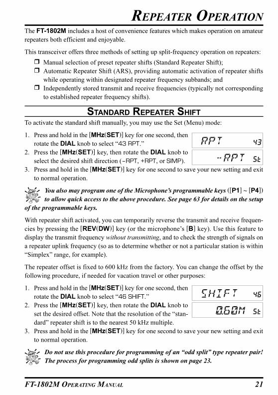
To activate the standard shift manually, you may use the Set (Menu) mode:
1. Press and hold in the [MHz(SET)] key for one second, then
rotate the DIAL knob to select “43 RPT.”
2. Press the [MHz(SET)] key, then rotate the DIAL knob to
select the desired shift direction (–RPT, +RPT, or SIMP).
3. Press and hold in the [MHz(SET)] key for one second to save your new setting and exit
to normal operation.
You also may program one of the Microphone’s programmable keys ([P1] ~ [P4])
to allow quick access to the above procedure. See page 63 for details on the setup
of the programmable keys.
With repeater shift activated, you can temporarily reverse the transmit and receive frequen-
cies by pressing the [REV(DW)] key (or the microphone’s [B] key). Use this feature to
display the transmit frequency without transmitting, and to check the strength of signals on
a repeater uplink frequency (so as to determine whether or not a particular station is within
“Simplex” range, for example).
The repeater offset is fixed to 600 kHz from the factory. You can change the offset by the
following procedure, if needed for vacation travel or other purposes:
1. Press and hold in the [MHz(SET)] key for one second, then
rotate the DIAL knob to select “46 SHIFT.”
2. Press the [MHz(SET)] key, then rotate the DIAL knob to
set the desired offset. Note that the resolution of the “stan-
dard” repeater shift is to the nearest 50 kHz multiple.
3. Press and hold in the [MHz(SET)] key for one second to save your new setting and exit
to normal operation.
Do not use this procedure for programming of an “odd split” type repeater pair!
The process for programming odd splits is shown on page 23.

22 FT-1802M OPERATING MANUAL
REPEATER OPERATION
AUTOMATIC REPEATER SHIFT
The ARS (Automatic Repeater Shift) feature in this transceiver allows easy and convenient
repeater operation by automatically activating the repeater shift function whenever you tune
to a standard repeater subband. The ARS function is preset at the factory to conform to the
standards for the country to which it is exported.
The ARS function is enabled at the factory. To disable it:
1. Press and hold in the [MHz(SET)] key for one second, then
rotate the DIAL knob to select “4 ARS.”
2. Press the [MHz(SET)] key, then rotate the DIAL knob to
change the display to “OFF.”
3. Press and hold in the [MHz(SET)] key for one second to save your new setting and exit
to normal operation.
To enable the ARS function again, select “ON” in step 2 above.
European Version
Version A145.1 145.5
145.6 145.8
146.0 146.4 147.0 147.6 148.0
146.6 147.4
ARS-Repeater Subbands
23FT-1802M OPERATING MANUAL
REPEATER OPERATION
SEPARATE TRANSMIT FREQUENCY MEMORIES (“ODD SPLITS”)
All memory channels can store independent receive and transmit frequencies, to accommo-
date occasional non-standard offsets with greater frequency resolution than is available us-
ing the “standard” shift feature.
1. First store the receive (repeater output) frequency. In the VFO mode, tune the transceiver
to the desired receive frequency. Now press and hold in the [D/MR(MW)] key on the
front panel for one second.
2. Within five seconds of pressing the [D/MR(MW)] key, use the DIAL knob or microphone’s
[UP]/[DWN] buttons to select the desired memory channel into which you wish to store
this frequency pair.
3. Now press the [D/MR(MW)] key momentarily to store the receive frequency into the
selected memory.
4. Next store the transmit (repeater input) frequency. Since you are still in the VFO mode,
tune the transceiver to the desired transmit frequency.
5. Now press and hold in the [D/MR(MW)] key for one second.
6. Press and hold in the PTT switch, and press the [D/MR(MW)] key momentarily while
holding in the PTT switch. This will not cause transmission, but rather it will instruct the
transceiver that you are programming a separate transmit frequency into memory.
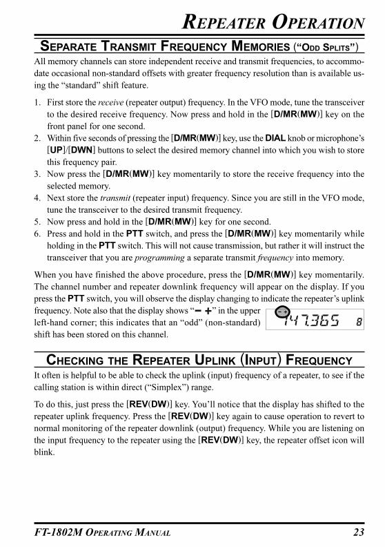
When you have finished the above procedure, press the [D/MR(MW)] key momentarily.
The channel number and repeater downlink frequency will appear on the display. If you
press the PTT switch, you will observe the display changing to indicate the repeater’s uplink
frequency. Note also that the display shows “ ” in the upper
left-hand corner; this indicates that an “odd” (non-standard)
shift has been stored on this channel.
CHECKING THE REPEATER UPLINK (INPUT) FREQUENCY
It often is helpful to be able to check the uplink (input) frequency of a repeater, to see if the
calling station is within direct (“Simplex”) range.
To do this, just press the [REV(DW)] key. You’ll notice that the display has shifted to the
repeater uplink frequency. Press the [REV(DW)] key again to cause operation to revert to
normal monitoring of the repeater downlink (output) frequency. While you are listening on
the input frequency to the repeater using the [REV(DW)] key, the repeater offset icon will
blink.

24 FT-1802M OPERATING MANUAL
CTCSS OPERATION
Many repeater systems require that a very-low-frequency audio tone be superimposed on your
FM carrier in order to activate the repeater. This helps prevent false activation of the repeater by
radar or spurious signals from other transmitters. This tone system, called “CTCSS” (Continu-
ous Tone Coded Squelch System), is included in your FT-1802M, and is very easy to activate.
CTCSS setup involves two actions: setting the Tone Mode and then setting of the
Tone Frequency. These actions are set up by using the Set (Menu) mode, selec-
tions #49 (SQL.TYP) and #52 (TN FRQ).
1. Press and hold in the [MHz(SET)] key for one second, then
rotate the DIAL knob to select “49 SQL.TYP.”
2. Press the [MHz(SET)] key, then rotate the DIAL knob so that “TONE” appears on the
display; this activates the CTCSS Encoder, which allows
repeater access.
3. Rotating the DIAL knob one more click clockwise in the above step will cause “TSQL”
to appear. When “TSQL” appears, this means that the Tone Squelch system is active,
which mutes your FT-1802M’s receiver until it receives a call from another radio send-
ing out a matching CTCSS tone. This can help keep your radio quiet until a specific call
is received, which may be helpful while operating in congested areas.
1) You may notice a “RV TN” indication on the display while you rotate the
DIAL knob in this step; this means that the Reverse Tone Squelch system is
active, which mutes your FT-1802M’s receiver (instead of opening the squelch) when
it receives a call from the radio sending a matched CTCSS tone. The “T SQ” icon will
blink on the display when the Reverse Tone Squelch system is activated.
2) You may notice a “DCS” indication on the display while you rotate the DIAL knob
still more. We’ll discuss the Digital Code Squelch system shortly.
4. When you have made your selection of the CTCSS tone mode, press the [MHz(SET)]
key momentarily, then rotate the DIAL knob three clicks clockwise to select Menu “52
TN FRQ.” This Menu selection allows setting of the CTCSS
tone frequency to be used.
5. Press the [MHz(SET)] key to enable adjust-
ment of the CTCSS frequency.
6. R o t a t e t h e
DIAL knob un-
til the display indicates the Tone Frequency
you need to be using.
7. When you have made your selection, press
and hold in the [MHz(SET)] key for one
second to save the new setting and exit to
normal operation.
CTCSS/DCS/EPCS OPERATION
CTCSS TONE FREQUENCY (Hz)
67.0 69.3 71.9 74.4 77.0 79.7
82.5 85.4 88.5 91.5 94.8 97.4
100.0 103.5 107.2 110.9 114.8 118.8
123.0 127.3 131.8 136.5 141.3 146.2
151.4 156.7 159.8 162.2 165.5 167.9
171.3 173.8 177.3 179.9 183.5 186.2
189.9 192.8 196.6 199.5 203.5 206.5
210.7 218.1 225.7 229.1 233.6 241.8
250.3 254.1 – – – –
25FT-1802M OPERATING MANUAL
Your repeater may or may not re-transmit a CTCSS tone - some systems just use
CTCSS to control access to the repeater, but don’t pass it along when transmit-
ting. If the S-Meter deflects, but the FT-1802M is not passing audio, repeat steps “1”
through “3” above, but rotate the DIAL knob so that “TONE” appears - this will allow
you to hear all traffic on the channel being received.
You may use the Menu to re-program one of the Microphone’s programmable keys for
quick access to Menu #52 (TN FRQ), from which you can perform the above setup pro-
cedure. See page 63 for details on the setup of the programmable keys.
DCS OPERATION
Another form of tone access control is Digital Code Squelch, or DCS. It is a newer, more
advanced tone system which generally provides more immunity from false paging than does
CTCSS. The DCS Encoder/Decoder is built into your FT-1802M, and operation is very
similar to that just described for CTCSS. Your repeater system may be configured for DCS;
if not, it is frequently quite useful in Simplex operation if your friend(s) use transceivers
equipped with this advanced feature.
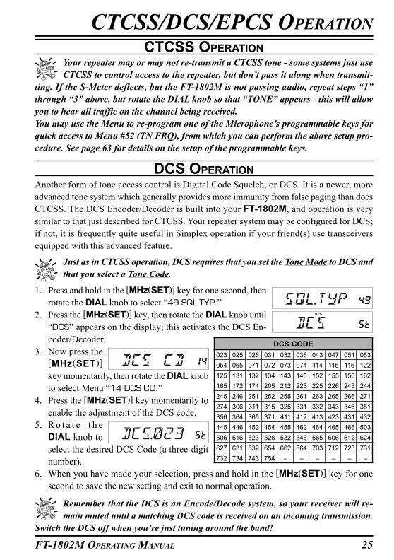
Just as in CTCSS operation, DCS requires that you set the Tone Mode to DCS and
that you select a Tone Code.
1. Press and hold in the [MHz(SET)] key for one second, then
rotate the DIAL knob to select “49 SQL.TYP.”
2. Press the [MHz(SET)] key, then rotate the DIAL knob until
“DCS” appears on the display; this activates the DCS En-
coder/Decoder.
3. Now press the
[MHz(SET)]
key momentarily, then rotate the DIAL knob
to select Menu “14 DCS CD.”
4. Press the [MHz(SET)] key momentarily to
enable the adjustment of the DCS code.
5. R o t a t e t h e
DIAL knob to
select the desired DCS Code (a three-digit
number).
6. When you have made your selection, press and hold in the [MHz(SET)] key for one
second to save the new setting and exit to normal operation.
Remember that the DCS is an Encode/Decode system, so your receiver will re-
main muted until a matching DCS code is received on an incoming transmission.
Switch the DCS off when you’re just tuning around the band!
CTCSS OPERATION
CTCSS/DCS/EPCS OPERATION
DCS CODE
023 025 026 031 032 036 043 047 051 053
054 065 071 072 073 074 114 115 116 122
125 131 132 134 143 145 152 155 156 162
165 172 174 205 212 223 225 226 243 244
245 246 251 252 255 261 263 265 266 271
274 306 311 315 325 331 332 343 346 351
356 364 365 371 411 412 413 423 431 432
445 446 452 454 455 462 464 465 466 503
506 516 523 526 532 546 565 606 612 624
627 631 632 654 662 664 703 712 723 731
732 734 743 754 – – – – – –
26 FT-1802M OPERATING MANUAL
TONE SEARCH SCANNING
In operating situations where you don’t know the CTCSS tone or DCS code being used by
another station or stations, you can command the radio to listen to the incoming signal and
scan in search of the tone being used. Two things must be remembered in this regard:
� You must be sure that your repeater uses the same tone type (CTCSS vs. DCS).
� Some repeaters do not pass the CTCSS tone or DCS code; you may have to listen to the
station(s) transmitting on the repeater uplink (input) frequency in order to allow Tone
Search Scanning to work.
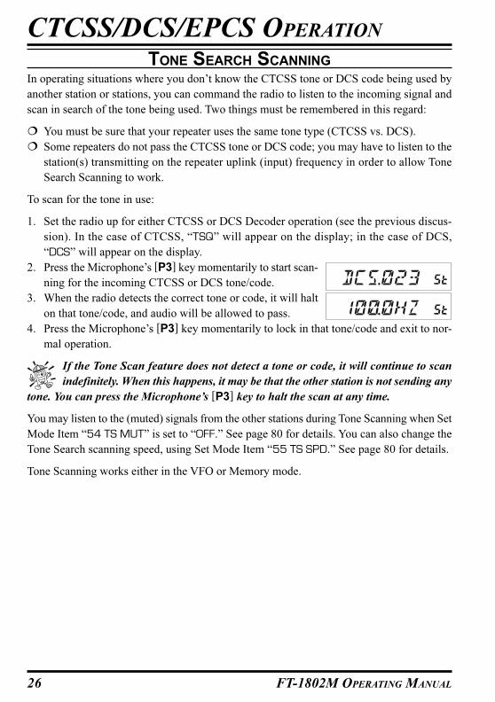
To scan for the tone in use:
1. Set the radio up for either CTCSS or DCS Decoder operation (see the previous discus-
sion). In the case of CTCSS, “TSQ” will appear on the display; in the case of DCS,
“DCS” will appear on the display.
2. Press the Microphone’s [P3] key momentarily to start scan-
ning for the incoming CTCSS or DCS tone/code.
3. When the radio detects the correct tone or code, it will halt
on that tone/code, and audio will be allowed to pass.
4. Press the Microphone’s [P3] key momentarily to lock in that tone/code and exit to nor-
mal operation.
If the Tone Scan feature does not detect a tone or code, it will continue to scan
indefinitely. When this happens, it may be that the other station is not sending any
tone. You can press the Microphone’s [P3] key to halt the scan at any time.
You may listen to the (muted) signals from the other stations during Tone Scanning when Set
Mode Item “54 TS MUT” is set to “OFF.” See page 80 for details. You can also change the
Tone Search scanning speed, using Set Mode Item “55 TS SPD.” See page 80 for details.
Tone Scanning works either in the VFO or Memory mode.
CTCSS/DCS/EPCS OPERATION
27FT-1802M OPERATING MANUAL
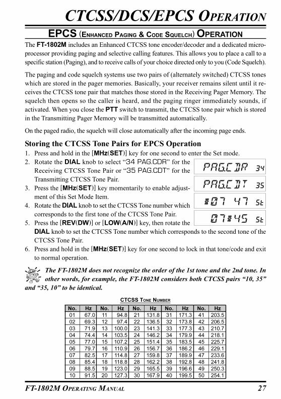
EPCS (ENHANCED PAGING & CODE SQUELCH) OPERATION
The FT-1802M includes an Enhanced CTCSS tone encoder/decoder and a dedicated micro-
processor providing paging and selective calling features. This allows you to place a call to a
specific station (Paging), and to receive calls of your choice directed only to you (Code Squelch).
The paging and code squelch systems use two pairs of (alternately switched) CTCSS tones
which are stored in the pager memories. Basically, your receiver remains silent until it re-
ceives the CTCSS tone pair that matches those stored in the Receiving Pager Memory. The
squelch then opens so the caller is heard, and the paging ringer immediately sounds, if
activated. When you close the PTT switch to transmit, the CTCSS tone pair which is stored
in the Transmitting Pager Memory will be transmitted automatically.
On the paged radio, the squelch will close automatically after the incoming page ends.
Storing the CTCSS Tone Pairs for EPCS Operation
1. Press and hold in the [MHz(SET)] key for one second to enter the Set mode.
2. Rotate the DIAL knob to select “34 PAG.CDR” for the
Receiving CTCSS Tone Pair or “35 PAG.CDT” for the
Transmitting CTCSS Tone Pair.
3. Press the [MHz(SET)] key momentarily to enable adjust-
ment of this Set Mode Item.
4. Rotate the DIAL knob to set the CTCSS Tone number which
corresponds to the first tone of the CTCSS Tone Pair.
5. Press the [REV(DW)] or [LOW(A/N)] key, then rotate the
DIAL knob to set the CTCSS Tone number which corresponds to the second tone of the
CTCSS Tone Pair.
6. Press and hold in the [MHz(SET)] key for one second to lock in that tone/code and exit
to normal operation.
The FT-1802M does not recognize the order of the 1st tone and the 2nd tone. In
other words, for example, the FT-1802M considers both CTCSS pairs “10, 35”
and “35, 10” to be identical.
CTCSS/DCS/EPCS OPERATION
Hz
67.0
69.3
71.9
74.4
77.0
79.7
82.5
85.4
88.5
91.5
No.
01
02
03
04
05
06
07
08
09
10
Hz
94.8
97.4
100.0
103.5
107.2
110.9
114.8
118.8
123.0
127.3
No.
11
12
13
14
15
16
17
18
19
20
Hz
131.8
136.5
141.3
146.2
151.4
156.7
159.8
162.2
165.5
167.9
No.
21
22
23
24
25
26
27
28
29
30
Hz
171.3
173.8
177.3
179.9
183.5
186.2
189.9
192.8
196.6
199.5
No.
31
32
33
34
35
36
37
38
39
40
Hz
203.5
206.5
210.7
218.1
225.7
229.1
233.6
241.8
250.3
254.1
No.
41
42
43
44
45
46
47
48
49
50
CTCSS TONE NUMBER
28 FT-1802M OPERATING MANUAL
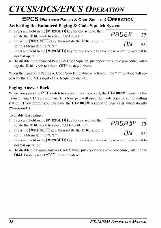
Activating the Enhanced Paging & Code Squelch System
1. Press and hold in the [MHz(SET)] key for one second, then
rotate the DIAL knob to select “32 PAGER.”
2. Press the [MHz(SET)] key, then rotate the DIAL knob to
set this Menu item to “ON.”
3. Press and hold in the [MHz(SET)] key for one second to save the new setting and exit to
normal operation.
4. To disable the Enhanced Paging & Code Squelch, just repeat the above procedure, rotat-
ing the DIAL knob to select “OFF” in step 2 above.
When the Enhanced Paging & Code Squelch feature is activated, the “P” notation will ap-
pear by the 100 MHz digit of the frequency display.
Paging Answer Back
When you press the PTT switch to respond to a page call, the FT-1802M transmits the
Transmitting CTCSS Tone pair. This tone pair will open the Code Squelch of the calling
station. If you prefer, you can have the FT-1802M respond to page calls automatically
(“transpond”).
To enable this feature:
1. Press and hold in the [MHz(SET)] key for one second, then
rotate the DIAL knob to select “33 PAG.ABK.”
2. Press the [MHz(SET)] key, then rotate the DIAL knob to
set this Menu item to “ON.”
3. Press and hold in the [MHz(SET)] key for one second to save the new setting and exit to
normal operation.
4. To disable the Paging Answer Back feature, just repeat the above procedure, rotating the
DIAL knob to select “OFF” in step 2 above.
EPCS (ENHANCED PAGING & CODE SQUELCH) OPERATION
CTCSS/DCS/EPCS OPERATION

29FT-1802M OPERATING MANUAL
CTCSS/DCS/EPCS BELL OPERATION
During CTCSS Decode, DCS, or EPCS operation, you may set up the FT-1802M such that
a ringing “bell” sound alerts you to the fact that a call is coming in. Here is the procedure for
activating the CTCSS/DCS/EPCS Bell:
1. Set the transceiver up for CTCSS Decode (“Tone Squelch”), DCS, or EPCS operation,
as described previously.
2. Adjust the operating frequency to the desired channel.
3. Press and hold in the [MHz(SET)] key for one second, then
rotate the DIAL knob to select “7 BELL.”
4. Rotate the DIAL knob to set the desired number of rings of the Bell. The available
choices are 1, 3, 5, or 8 rings, CNTNUE (continuous ring-
ing), or OFF.
5. Press and hold in the [MHz(SET)] key for one second to save the new setting and exit to
normal operation.
When you are called by a station whose transceiver is sending a CTCSS tone, DCS code, or
CTCSS code pair which matches that set into your Decoder, the Bell will ring in accordance
with this programming.
When the CTCSS/DCS/EPCS Bell is activated, the “ ” icon
will appear on the display.
CTCSS/DCS/EPCS OPERATION
30 FT-1802M OPERATING MANUAL
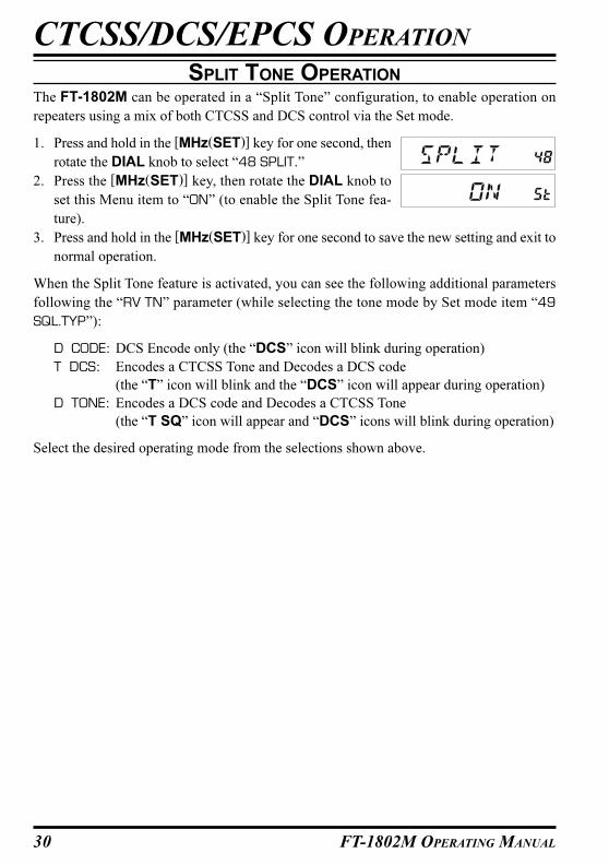
SPLIT TONE OPERATION
The FT-1802M can be operated in a “Split Tone” configuration, to enable operation on
repeaters using a mix of both CTCSS and DCS control via the Set mode.
1. Press and hold in the [MHz(SET)] key for one second, then
rotate the DIAL knob to select “48 SPLIT.”
2. Press the [MHz(SET)] key, then rotate the DIAL knob to
set this Menu item to “ON” (to enable the Split Tone fea-
ture).
3. Press and hold in the [MHz(SET)] key for one second to save the new setting and exit to
normal operation.
When the Split Tone feature is activated, you can see the following additional parameters
following the “RV TN” parameter (while selecting the tone mode by Set mode item “49
SQL.TYP”):
D CODE: DCS Encode only (the “DCS” icon will blink during operation)
T DCS: Encodes a CTCSS Tone and Decodes a DCS code
(the “T” icon will blink and the “DCS” icon will appear during operation)
D TONE: Encodes a DCS code and Decodes a CTCSS Tone
(the “T SQ” icon will appear and “DCS” icons will blink during operation)
Select the desired operating mode from the selections shown above.
CTCSS/DCS/EPCS OPERATION
31FT-1802M OPERATING MANUAL
CTCSS/DCS/EPCS OPERATION
NOTE
32 FT-1802M OPERATING MANUAL
DTMF OPERATION
The Microphone’s 16-button keypad allows easy DTMF dialing for Autopatch, repeater
control, or Internet-link access purposes. Besides numerical digits [0] through [9], the key-
pad includes the [�] and [#] digits, plus the [A], [B], [C], and [D] tones often used for
repeater control.
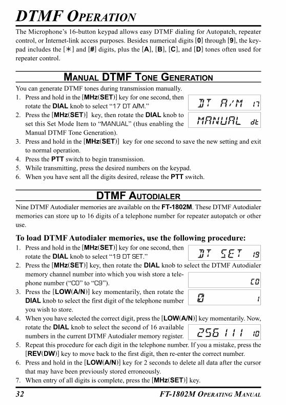
MANUAL DTMF TONE GENERATION
You can generate DTMF tones during transmission manually.
1. Press and hold in the [MHz(SET)] key for one second, then
rotate the DIAL knob to select “17 DT A/M.”
2. Press the [MHz(SET)] key, then rotate the DIAL knob to
set this Set Mode Item to “MANUAL” (thus enabling the
Manual DTMF Tone Generation).
3. Press and hold in the [MHz(SET)] key for one second to save the new setting and exit
to normal operation.
4. Press the PTT switch to begin transmission.
5. While transmitting, press the desired numbers on the keypad.
6. When you have sent all the digits desired, release the PTT switch.
DTMF AUTODIALER
Nine DTMF Autodialer memories are available on the FT-1802M. These DTMF Autodialer
memories can store up to 16 digits of a telephone number for repeater autopatch or other
use.
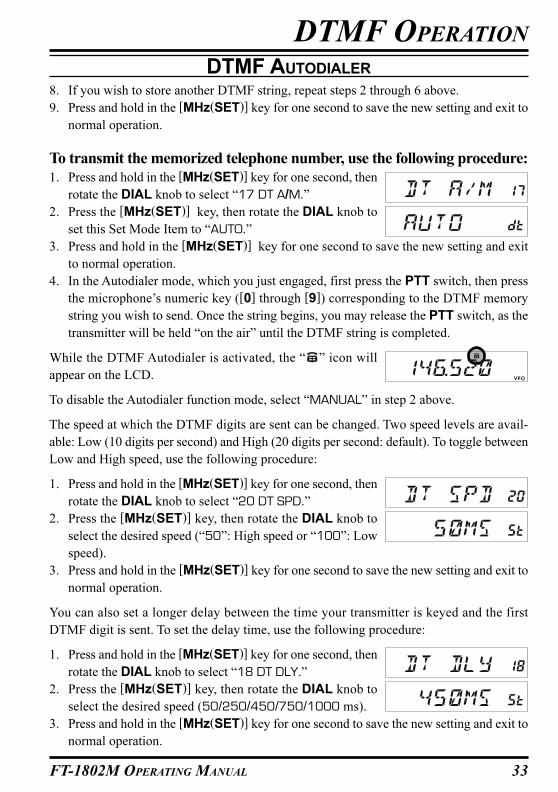
To load DTMF Autodialer memories, use the following procedure:
1. Press and hold in the [MHz(SET)] key for one second, then
rotate the DIAL knob to select “19 DT SET.”
2. Press the [MHz(SET)] key, then rotate the DIAL knob to select the DTMF Autodialer
memory channel number into which you wish store a tele-
phone number (“C0” to “C9”).
3. Press the [LOW(A/N)] key momentarily, then rotate the
DIAL knob to select the first digit of the telephone number
you wish to store.
4. When you have selected the correct digit, press the [LOW(A/N)] key momentarily. Now,
rotate the DIAL knob to select the second of 16 available
numbers in the current DTMF Autodialer memory register.
5. Repeat this procedure for each digit in the telephone number. If you a mistake, press the
[REV(DW)] key to move back to the first digit, then re-enter the correct number.
6. Press and hold in the [LOW(A/N)] key for 2 seconds to delete all data after the cursor
that may have been previously stored erroneously.
7. When entry of all digits is complete, press the [MHz(SET)] key.
33FT-1802M OPERATING MANUAL
8. If you wish to store another DTMF string, repeat steps 2 through 6 above.
9. Press and hold in the [MHz(SET)] key for one second to save the new setting and exit to
normal operation.
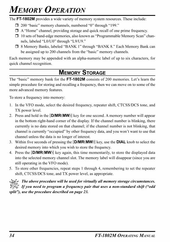
To transmit the memorized telephone number, use the following procedure:
1. Press and hold in the [MHz(SET)] key for one second, then
rotate the DIAL knob to select “17 DT A/M.”
2. Press the [MHz(SET)] key, then rotate the DIAL knob to
set this Set Mode Item to “AUTO.”
3. Press and hold in the [MHz(SET)] key for one second to save the new setting and exit
to normal operation.
4. In the Autodialer mode, which you just engaged, first press the PTT switch, then press
the microphone’s numeric key ([0] through [9]) corresponding to the DTMF memory
string you wish to send. Once the string begins, you may release the PTT switch, as the
transmitter will be held “on the air” until the DTMF string is completed.
While the DTMF Autodialer is activated, the “ ” icon will
appear on the LCD.
To disable the Autodialer function mode, select “MANUAL” in step 2 above.
The speed at which the DTMF digits are sent can be changed. Two speed levels are avail-
able: Low (10 digits per second) and High (20 digits per second: default). To toggle between
Low and High speed, use the following procedure:
1. Press and hold in the [MHz(SET)] key for one second, then
rotate the DIAL knob to select “20 DT SPD.”
2. Press the [MHz(SET)] key, then rotate the DIAL knob to
select the desired speed (“50”: High speed or “100”: Low
speed).
3. Press and hold in the [MHz(SET)] key for one second to save the new setting and exit to
normal operation.
You can also set a longer delay between the time your transmitter is keyed and the first
DTMF digit is sent. To set the delay time, use the following procedure:
1. Press and hold in the [MHz(SET)] key for one second, then
rotate the DIAL knob to select “18 DT DLY.”
2. Press the [MHz(SET)] key, then rotate the DIAL knob to
select the desired speed (50/250/450/750/1000 ms).
3. Press and hold in the [MHz(SET)] key for one second to save the new setting and exit to
normal operation.
DTMF OPERATION
DTMF AUTODIALER
34 FT-1802M OPERATING MANUAL
The FT-1802M provides a wide variety of memory system resources. These include:
� 200 “basic” memory channels, numbered “0” through “199.”
� A “Home” channel, providing storage and quick recall of one prime frequency.
� 10 sets of band-edge memories, also known as “Programmable Memory Scan” chan-
nels, labeled “L0/U0” through “L9/U9.”
� 8 Memory Banks, labeled “BANK 1” through “BANK 8.” Each Memory Bank can
be assigned up to 200 channels from the “basic” memory channels.
Each memory may be appended with an alpha-numeric label of up to six characters, for
quick channel recognition.
MEMORY STORAGE
The “basic” memory bank for the FT-1802M consists of 200 memories. Let’s learn the
simple procedure for storing and recalling a frequency, then we can move on to some of the
more advanced memory features.
To store a frequency into memory:
1. In the VFO mode, select the desired frequency, repeater shift, CTCSS/DCS tone, and
TX power level.
2. Press and hold in the [D/MR(MW)] key for one second. A memory number will appear
in the bottom right-hand corner of the display. If the channel number is blinking, there
currently is no data stored on that channel; if the channel number is not blinking, that
channel is currently “occupied” by other frequency data, and you won’t want to use that
channel unless the data is no longer of interest.
3. Within five seconds of pressing the [D/MR(MW)] key, use the DIAL knob to select the
desired memory into which you wish to store the frequency.
4. Press the [D/MR(MW)] key again, this time momentarily, to store the displayed data
into the selected memory channel slot. The memory label will disappear (since you are
still operating in the VFO mode).
5. To store other frequencies, repeat steps 1 through 4, remembering to set the repeater
shift, CTCSS/DCS tone, and TX power level, as appropriate.
The above procedure will be used for virtually all memory storage circumstances.
If you need to program a frequency pair that uses a non-standard shift (“odd
split”), use the procedure described on page 23.
MEMORY OPERATION
35FT-1802M OPERATING MANUAL
MEMORY OPERATION
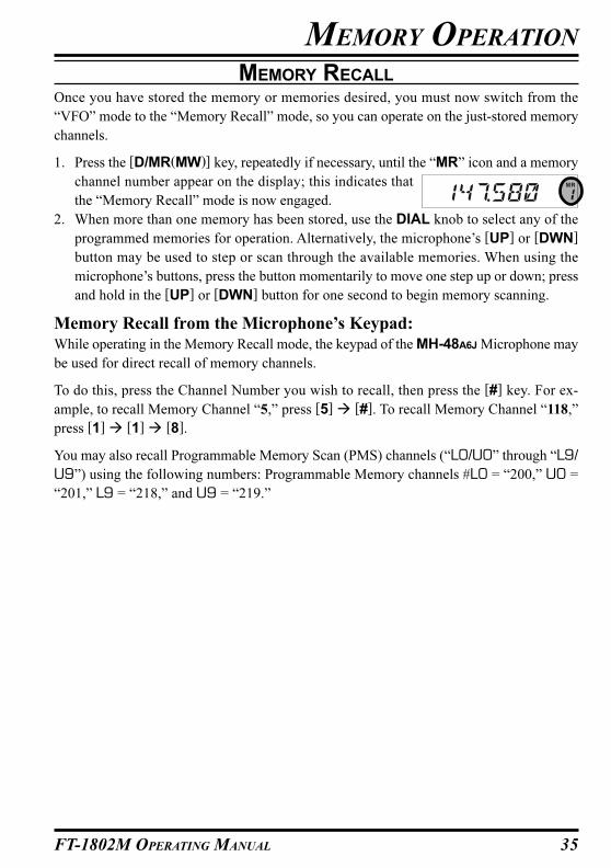
MEMORY RECALL
Once you have stored the memory or memories desired, you must now switch from the
“VFO” mode to the “Memory Recall” mode, so you can operate on the just-stored memory
channels.
1. Press the [D/MR(MW)] key, repeatedly if necessary, until the “MR” icon and a memory
channel number appear on the display; this indicates that
the “Memory Recall” mode is now engaged.
2. When more than one memory has been stored, use the DIAL knob to select any of the
programmed memories for operation. Alternatively, the microphone’s [UP] or [DWN]
button may be used to step or scan through the available memories. When using the
microphone’s buttons, press the button momentarily to move one step up or down; press
and hold in the [UP] or [DWN] button for one second to begin memory scanning.
Memory Recall from the Microphone’s Keypad:
While operating in the Memory Recall mode, the keypad of the MH-48A6J Microphone may
be used for direct recall of memory channels.
To do this, press the Channel Number you wish to recall, then press the [#] key. For ex-
ample, to recall Memory Channel “5,” press [5] � [#]. To recall Memory Channel “118,”
press [1] � [1] � [8].
You may also recall Programmable Memory Scan (PMS) channels (“L0/U0” through “L9/
U9”) using the following numbers: Programmable Memory channels #L0 = “200,” U0 =
“201,” L9 = “218,” and U9 = “219.”

36 FT-1802M OPERATING MANUAL
LABELING MEMORIES
You may wish to append an alpha-numeric “Tag” (label) to a memory or memories, to aid in
recollection of the channel’s use (such as club name, etc.). This is easily accomplished using
the Set (Menu) mode.
1. Recall the memory channel on which you wish to append a
label.
2. Press and hold in the [MHz(SET)] key for one second, then
rotate the DIAL knob to select “30 NM SET.”
3. Press the [MHz(SET)] key. You will notice the first charac-
ter location blinking, indicating that you are now in the Al-
pha-Numeric (“A/N”) entry mode. Within the A/N entry
mode, rotate the DIAL knob to select characters; pressing
the [LOW(A/N)] key will move the character’s entry location to the right.
4. Rotate the DIAL knob to select the desired number, letter,
or symbol, then press the [LOW(A/N)] key to move the
next character’s location. Move two slots if you want to put in a space. Press the
[REV(DW)] key if you want to “backspace” one slot.
5. Repeat step 4, as necessary, to complete the name tag (up to six characters) for your
memory, then press the [MHz(SET)] key momentarily to
save the A/N name just entered.
6. Press and hold in the [MHz(SET)] key for one second to exit to normal operation.
While operating in the Memory Recall mode, press and hold in
the [LOW(A/N)] key for one second to toggle the display be-
tween indication of the frequency and the channel’s Alpha/Nu-
meric label.
MEMORY OPERATION
37FT-1802M OPERATING MANUAL
MEMORY OPERATION
MEMORY TUNING
Once you have recalled a particular memory channel, you may easily tune off that channel,
as though you were in the VFO mode.
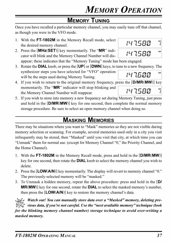
1. With the FT-1802M in the Memory Recall mode, select
the desired memory channel.
2. Press the [MHz(SET)] key momentarily. The “MR” indi-
cator will blink and the Memory Channel Number will dis-
appear; these indicates that the “Memory Tuning” mode has been engaged.
3. Rotate the DIAL knob, or press the [UP] or [DWN] keys, to tune to a new frequency. The
synthesizer steps you have selected for “VFO” operation
will be the steps used during Memory Tuning.
4. If you wish to return to the original memory frequency, press the [D/MR(MW)] key
momentarily. The “MR” indicator will stop blinking and
the Memory Channel Number will reappear.
5. If you wish to store into memory a new frequency set during Memory Tuning, just press
and hold in the [D/MR(MW)] key for one second, then complete the normal memory
storage procedure. Be sure to select an open memory channel when doing so.
MASKING MEMORIES
There may be situations where you want to “Mask” memories so they are not visible during
memory selection or scanning. For example, several memories used only in a city you visit
infrequently may be stored, then “Masked” until you visit that city, at which time you can
“Unmask” them for normal use. (except for Memory Channel “0,” the Priority Channel, and
the Home Channel).
1. With the FT-1802M in the Memory Recall mode, press and hold in the [D/MR(MW)]
key for one second, then rotate the DIAL knob to select the memory channel you wish to
delete.
2. Press the [LOW(A/N)] key momentarily. The display will revert to memory channel “0.”
The previously-selected memory will be “masked.”
3. To Unmask a hidden memory, repeat the above procedure: press and hold in the [D/
MR(MW)] key for one second, rotate the DIAL to select the masked memory’s number,
then press the [LOW(A/N)] key to restore the memory channel’s data.
Watch out! You can manually store data over a “Masked” memory, deleting pre-
vious data, if you’re not careful. Use the “next available memory” technique (look
for the blinking memory channel number) storage technique to avoid over-writing a
masked memory.
38 FT-1802M OPERATING MANUAL
MEMORY BANK OPERATION
The large number of memories available in the FT-1802M could be difficult to utilize with-
out some means of organizing them. Fortunately, the FT-1802M includes provision for
dividing the memories into as many as eight Memory Banks, so you can categorize the
memories in a manner convenient to you. You may enter and exit the “Memory Bank” mode
by a single press of the Microphone’s [�] key, as we shall see below.
Assigning Memories to a Memory Bank
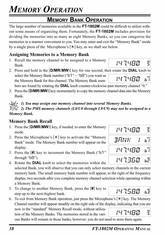
1. Recall the memory channel to be assigned to a Memory
Bank.
2. Press and hold in the [D/MR(MW)] key for one second, then rotate the DIAL knob to
select the Memory Bank number (“b1” ~ “b8”) you want as
the Memory Bank for this channel. The Memory Bank num-
bers are found by rotating the DIAL knob counter-clockwise past memory channel “0.”
3. Press the [D/MR(MW)] key momentarily to copy the memory channel data into the Memory
Bank.
1) You may assign one memory channel into several Memory Banks.
2) The PMS memory channels (L0/U0 through L9/U9) may not be assigned to a
Memory Bank.
Memory Bank Recall
1. Press the [D/MR(MW)] key, if needed, to enter the Memory
mode.
2. Press the Microphone’s [�] key to activate the “Memory
Bank” mode. The Memory Bank number will appear on the
display.
3. Press the [#] key to increment the Memory Bank (“b1”
through “b8”).
4. Rotate the DIAL knob to select the memories within the
selected Bank; you will observe that you can only select memory channels in the current
memory bank. The small memory bank number will appear, to the right of the frequency
display, two seconds after you complete memory channel selection while operating within
a Memory Bank.
5. To change to another Memory Bank, press the [#] key to
step up to the next-highest bank.
6. To exit from Memory Bank operation, just press the Microphone’s [�] key. The Memory
Channel number will appear steadily on the right side of the display, indicating that you are
now in the “standard” Memory Recall mode, without utiliza-
tion of the Memory Banks. The memories stored in the vari-
ous Banks will remain in those banks, however; you do not need to store them again.
MEMORY OPERATION
39FT-1802M OPERATING MANUAL
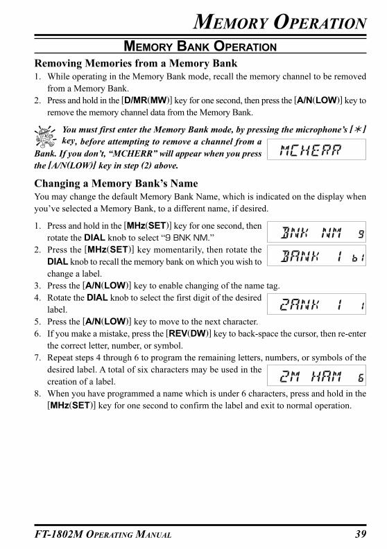
Removing Memories from a Memory Bank
1. While operating in the Memory Bank mode, recall the memory channel to be removed
from a Memory Bank.
2. Press and hold in the [D/MR(MW)] key for one second, then press the [A/N(LOW)] key to
remove the memory channel data from the Memory Bank.
You must first enter the Memory Bank mode, by pressing the microphone’s [� ]
key, before attempting to remove a channel from a
Bank. If you don’t, “MCHERR” will appear when you press
the [A/N(LOW)] key in step (2) above.
Changing a Memory Bank’s Name
You may change the default Memory Bank Name, which is indicated on the display when
you’ve selected a Memory Bank, to a different name, if desired.
1. Press and hold in the [MHz(SET)] key for one second, then
rotate the DIAL knob to select “9 BNK NM.”
2. Press the [MHz(SET)] key momentarily, then rotate the
DIAL knob to recall the memory bank on which you wish to
change a label.
3. Press the [A/N(LOW)] key to enable changing of the name tag.
4. Rotate the DIAL knob to select the first digit of the desired
label.
5. Press the [A/N(LOW)] key to move to the next character.
6. If you make a mistake, press the [REV(DW)] key to back-space the cursor, then re-enter
the correct letter, number, or symbol.
7. Repeat steps 4 through 6 to program the remaining letters, numbers, or symbols of the
desired label. A total of six characters may be used in the
creation of a label.
8. When you have programmed a name which is under 6 characters, press and hold in the
[MHz(SET)] key for one second to confirm the label and exit to normal operation.
MEMORY BANK OPERATION
MEMORY OPERATION
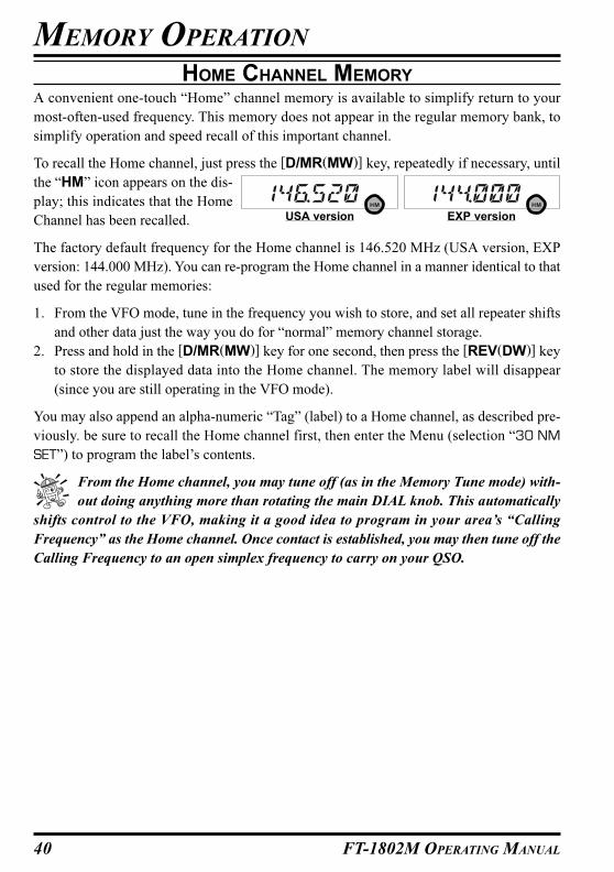
40 FT-1802M OPERATING MANUAL
HOME CHANNEL MEMORY
A convenient one-touch “Home” channel memory is available to simplify return to your
most-often-used frequency. This memory does not appear in the regular memory bank, to
simplify operation and speed recall of this important channel.
To recall the Home channel, just press the [D/MR(MW)] key, repeatedly if necessary, until
the “HM” icon appears on the dis-
play; this indicates that the Home
Channel has been recalled.
The factory default frequency for the Home channel is 146.520 MHz (USA version, EXP
version: 144.000 MHz). You can re-program the Home channel in a manner identical to that
used for the regular memories:
1. From the VFO mode, tune in the frequency you wish to store, and set all repeater shifts
and other data just the way you do for “normal” memory channel storage.
2. Press and hold in the [D/MR(MW)] key for one second, then press the [REV(DW)] key
to store the displayed data into the Home channel. The memory label will disappear
(since you are still operating in the VFO mode).
You may also append an alpha-numeric “Tag” (label) to a Home channel, as described pre-
viously. be sure to recall the Home channel first, then enter the Menu (selection “30 NM
SET”) to program the label’s contents.
From the Home channel, you may tune off (as in the Memory Tune mode) with-
out doing anything more than rotating the main DIAL knob. This automatically
shifts control to the VFO, making it a good idea to program in your area’s “Calling
Frequency” as the Home channel. Once contact is established, you may then tune off the
Calling Frequency to an open simplex frequency to carry on your QSO.
MEMORY OPERATION
USA version EXP version
41FT-1802M OPERATING MANUAL
MEMORY-ONLY MODE
Once memory channel programming has been completed, you may place the radio in a
“Memory Only” mode, whereby VFO and Home Channel operation are impossible. This
may be particularly useful during public-service events where a number of operators may be
using the radio for first time, and ultimate simplicity of channel selection is desired.
To place the radio into the Memory Only mode, turn it off. Now press and hold in the
[D/MR(MW)] key while turning the radio on. The VFO and Home Channel will now be
disabled.
To return to normal operation, repeat the above power-on procedure.
MEMORY OPERATION

42 FT-1802M OPERATING MANUAL
The FT-1802M’s scanning capability provides the operator with many convenient methods
of rapid frequency navigation.
BASIC SCANNER OPERATION
Before activating the scanner, make sure that the Squelch is set to silence the background
noise when no signal is present. Scanning is not possible while the Squelch is open (if noise
or signals are being heard).
Scanning may be started or stopped using the microphone’s [UP] or [DWN] button. The
following techniques are used for scanning:
� Pressing and holding in either the [UP] or [DWN] button for one second in the VFO
mode will cause upward or downward band scanning, respectively, to begin.
� Pressing and holding in either the [UP] or [DWN] button for one second in the Memory
mode will cause memory channel scanning toward a higher- or lower-numbered memory
channel, respectively.
� Scanning pauses when a signal opens the squelch, and the decimal point on the display
will blink. You can choose one of three scan-resume modes (described later).
� To halt the scan manually, the easiest way is to push the PTT switch on the microphone
momentarily (no transmission will occur while you are scanning). The scan may also be
halted manually by pressing the microphone’s [UP] or [DWN] button, or the [D/
MR(MW)] key.
In the factory default setting, the scanner sweeps all frequencies while the VFO
mode and all memory channels while the Memory mode. You may change the
sweep range of the VFO mode to ±1 MHz, ±2 MHz, or ±5 MHz, or sweep only those
Memory Channels with the same “first” or “first” and “second” digits of the alpha/nu-
meric tag as the first channel on which scanning started, using Set Mode items “28
MEM.SCN” and “56 VFO.SCN.” See pages 75 and 80 for details.
SCANNING

43FT-1802M OPERATING MANUAL
SCAN-RESUME OPTIONS
Three scan-resume modes are available on the FT-1802M:
� In the “BUSY” mode, the scanner will remain halted for as long as there is carrier present
on the channel; after the carrier drops at the end of the other station’s transmission,
scanning will resume.
� In the “HOLD” mode, the scanner will halt on a signal it encounters. It will not restart
automatically; you must manually re-initiate scanning if you wish to resume.
� In the “3SEC/5SEC/10SEC” mode, the scanner will halt for the selected resume time,
after which scanning will resume (whether or not the other station is still transmitting).
The default scan-stop mode is “BUSY.” To change the scan-resume mode, use the following
procedure:
1. Press and hold in the [MHz(SET)] key for one second, then
rotate the DIAL knob to select “41 RESUME.”
2. Press the [MHz(SET)] key, then rotate the DIAL knob to
select the desired scan-resume mode.
3. Press and hold in the [MHz(SET)] key for one second to save the new setting and exit to
normal operation.
SCANNING
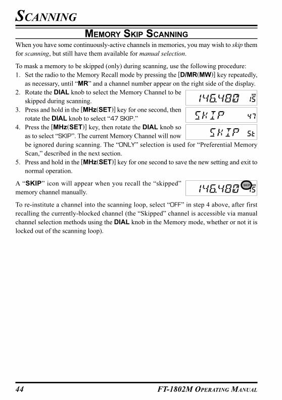
44 FT-1802M OPERATING MANUAL
MEMORY SKIP SCANNING
When you have some continuously-active channels in memories, you may wish to skip them
for scanning, but still have them available for manual selection.
To mask a memory to be skipped (only) during scanning, use the following procedure:
1. Set the radio to the Memory Recall mode by pressing the [D/MR(MW)] key repeatedly,
as necessary, until “MR” and a channel number appear on the right side of the display.
2. Rotate the DIAL knob to select the Memory Channel to be
skipped during scanning.
3. Press and hold in the [MHz(SET)] key for one second, then
rotate the DIAL knob to select “47 SKIP.”
4. Press the [MHz(SET)] key, then rotate the DIAL knob so
as to select “SKIP”. The current Memory Channel will now
be ignored during scanning. The “ONLY” selection is used for “Preferential Memory
Scan,” described in the next section.
5. Press and hold in the [MHz(SET)] key for one second to save the new setting and exit to
normal operation.
A “SKIP” icon will appear when you recall the “skipped”
memory channel manually.
To re-institute a channel into the scanning loop, select “OFF” in step 4 above, after first
recalling the currently-blocked channel (the “Skipped” channel is accessible via manual
channel selection methods using the DIAL knob in the Memory mode, whether or not it is
locked out of the scanning loop).
SCANNING
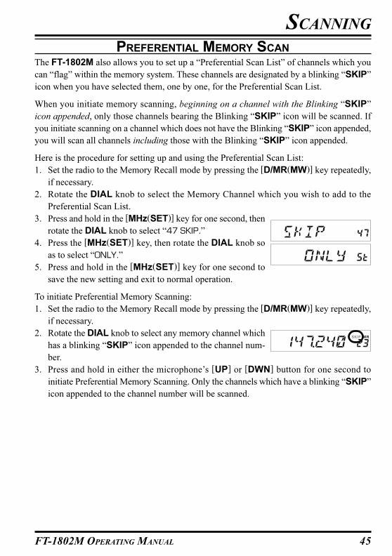
45FT-1802M OPERATING MANUAL
PREFERENTIAL MEMORY SCAN
The FT-1802M also allows you to set up a “Preferential Scan List” of channels which you
can “flag” within the memory system. These channels are designated by a blinking “SKIP”
icon when you have selected them, one by one, for the Preferential Scan List.
When you initiate memory scanning, beginning on a channel with the Blinking “SKIP”
icon appended, only those channels bearing the Blinking “SKIP” icon will be scanned. If
you initiate scanning on a channel which does not have the Blinking “SKIP” icon appended,
you will scan all channels including those with the Blinking “SKIP” icon appended.
Here is the procedure for setting up and using the Preferential Scan List:
1. Set the radio to the Memory Recall mode by pressing the [D/MR(MW)] key repeatedly,
if necessary.
2. Rotate the DIAL knob to select the Memory Channel which you wish to add to the
Preferential Scan List.
3. Press and hold in the [MHz(SET)] key for one second, then
rotate the DIAL knob to select “47 SKIP.”
4. Press the [MHz(SET)] key, then rotate the DIAL knob so
as to select “ONLY.”
5. Press and hold in the [MHz(SET)] key for one second to
save the new setting and exit to normal operation.
To initiate Preferential Memory Scanning:
1. Set the radio to the Memory Recall mode by pressing the [D/MR(MW)] key repeatedly,
if necessary.
2. Rotate the DIAL knob to select any memory channel which
has a blinking “SKIP” icon appended to the channel num-
ber.
3. Press and hold in either the microphone’s [UP] or [DWN] button for one second to
initiate Preferential Memory Scanning. Only the channels which have a blinking “SKIP”
icon appended to the channel number will be scanned.
SCANNING

46 FT-1802M OPERATING MANUAL
MEMORY BANK LINK SCAN
When the Memory Bank feature is engaged, the scanner sweeps only memory channels in
the current Memory Bank. However, if the Memory Bank Link Scan feature is enabled, you
may sweep the memory channels in several Memory Banks which you have selected.
To enable the Memory Bank Link Scan feature:
1. Set the radio to the Memory mode by pressing the [D/MR(MW)] key, if necessary.
2. Press and hold in the [MHz(SET)] key for one second, then
rotate the DIAL knob to select “8 BNK.LNK.”
3. Press the [MHz(SET)] key momentarily, then rotate the DIAL knob to select the first
Memory Bank (“b1” ~ “b8”) you wish to sweep using
Memory Bank Link Scan.
4. Press the [D/MR(MW)] key momentarily. A “SKIP” icon will blink above the Memory
Bank number, indicating this Memory Bank will now be
swept during Memory Bank Scan.
5. Repeat steps 3 and 4 above, to append the blinking “SKIP”
icon to any other Memory Banks you wish to sweep.
6. Now, press and hold in the [MHz(SET)] key for one second to initiate the Memory Bank
Link Scan.
7. To remove a Memory Bank from the Memory Bank Link Scan, repeat steps 2 - 4 above,
to delete the blinking “SKIP” icon from the Memory Bank number indication.
SCANNING

47FT-1802M OPERATING MANUAL
PROGRAMMABLE BAND-SCAN LIMITS
Besides band and memory scanning, this transceiver can be set to tune or scan only the
frequencies between user-defined lower and upper limits. For example, you may wish to
limit tuning/scanning to 144.3 - 148.0 MHz, to avoid encroachment on the SSB/CW sub-
band between 144.0 and 144.3 MHz
These scanning limits are stored in special “Sub-Band Limit Memories,” labeled L0/U0
through L9/U9, with “L” and “U” designations representing the Lower and Upper limits,
respectively.
To utilize this feature, use the following steps:
1. Store the lower edge of the desired scanning/tuning range in memory “L0”, and the
upper edge in memory “U0” (or, alternatively, in memories “L1/U1” through “L9/U9”).
2. With any of these memories recalled, press the [MHz(SET)] key momentarily to acti-
vate the Programmable Band-Scan Limits. The “PMS” icon will appear. Tuning and
scanning will now be limited within the just-programmed range.
To cancel the Sub-Band Limits and return to normal memory operation, press the [D/
MR(MW)] key momentarily.
Do not attempt to initiate “normal” scanning on any of the PMS memory chan-
nels. If you do, an error message will result; the “U/L” memories are dedicated
for the establishment of band scanning limits.
SCANNING
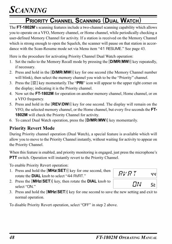
48 FT-1802M OPERATING MANUAL
PRIORITY CHANNEL SCANNING (DUAL WATCH)The FT-1802M’s scanning features include a two-channel scanning capability which allows
you to operate on a VFO, Memory channel, or Home channel, while periodically checking a
user-defined Memory Channel for activity. If a station is received on the Memory Channel
which is strong enough to open the Squelch, the scanner will pause on that station in accor-
dance with the Scan-Resume mode set via Menu item “41 RESUME.” See page 43.
Here is the procedure for activating Priority Channel Dual Watch operation:
1. Set the radio to the Memory Recall mode by pressing the [D/MR(MW)] key repeatedly,
if necessary.
2. Press and hold in the [D/MR(MW)] key for one second (the Memory Channel number
will blink), then select the memory channel you wish to be the “Priority” channel.
3. Press the [ ] key momentarily.The “PRI” icon will appear to the upper right corner on
the display; indicating it is the Priority channel.
4. Now set the FT-1802M for operation on another memory channel, Home channel, or on
a VFO frequency.
5. Press and hold in the [REV(DW)] key for one second. The display will remain on the
VFO, the selected memory channel, or the Home channel, but every five seconds the FT-
1802M will check the Priority Channel for activity.
6. To cancel Dual Watch operation, press the [D/MR(MW)] key momentarily.
Priority Revert Mode
During Priority channel operation (Dual Watch), a special feature is available which will
allow you to move to the Priority Channel instantly, without waiting for activity to appear on
the Priority Channel.
When this feature is enabled, and priority monitoring is engaged, just press the microphone’s
PTT switch. Operation will instantly revert to the Priority Channel.
To enable Priority Revert operation:
1. Press and hold the [MHz(SET)] key for one second, then
rotate the DIAL knob to select “44 RVRT.”
2. Press the [MHz(SET)] key, then rotate the DIAL knob to
select “ON.”
3. Press and hold the [MHz(SET)] key for one second to save the new setting and exit to
normal operation.
To disable Priority Revert operation, select “OFF” in step 2 above.
SCANNING
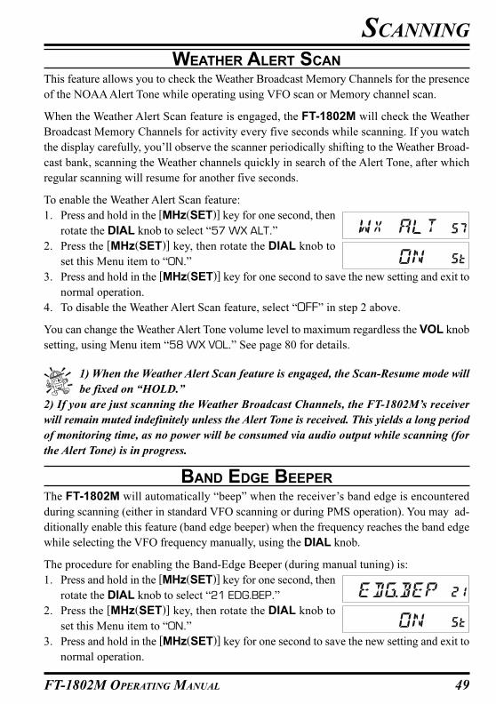
49FT-1802M OPERATING MANUAL
WEATHER ALERT SCAN
This feature allows you to check the Weather Broadcast Memory Channels for the presence
of the NOAA Alert Tone while operating using VFO scan or Memory channel scan.
When the Weather Alert Scan feature is engaged, the FT-1802M will check the Weather
Broadcast Memory Channels for activity every five seconds while scanning. If you watch
the display carefully, you’ll observe the scanner periodically shifting to the Weather Broad-
cast bank, scanning the Weather channels quickly in search of the Alert Tone, after which
regular scanning will resume for another five seconds.
To enable the Weather Alert Scan feature:
1. Press and hold in the [MHz(SET)] key for one second, then
rotate the DIAL knob to select “57 WX ALT.”
2. Press the [MHz(SET)] key, then rotate the DIAL knob to
set this Menu item to “ON.”
3. Press and hold in the [MHz(SET)] key for one second to save the new setting and exit to
normal operation.
4. To disable the Weather Alert Scan feature, select “OFF” in step 2 above.
You can change the Weather Alert Tone volume level to maximum regardless the VOL knob
setting, using Menu item “58 WX VOL.” See page 80 for details.
1) When the Weather Alert Scan feature is engaged, the Scan-Resume mode will
be fixed on “HOLD.”
2) If you are just scanning the Weather Broadcast Channels, the FT-1802M’s receiver
will remain muted indefinitely unless the Alert Tone is received. This yields a long period
of monitoring time, as no power will be consumed via audio output while scanning (for
the Alert Tone) is in progress.
BAND EDGE BEEPER
The FT-1802M will automatically “beep” when the receiver’s band edge is encountered
during scanning (either in standard VFO scanning or during PMS operation). You may ad-
ditionally enable this feature (band edge beeper) when the frequency reaches the band edge
while selecting the VFO frequency manually, using the DIAL knob.
The procedure for enabling the Band-Edge Beeper (during manual tuning) is:
1. Press and hold in the [MHz(SET)] key for one second, then
rotate the DIAL knob to select “21 EDG.BEP.”
2. Press the [MHz(SET)] key, then rotate the DIAL knob to
set this Menu item to “ON.”
3. Press and hold in the [MHz(SET)] key for one second to save the new setting and exit to
normal operation.
SCANNING
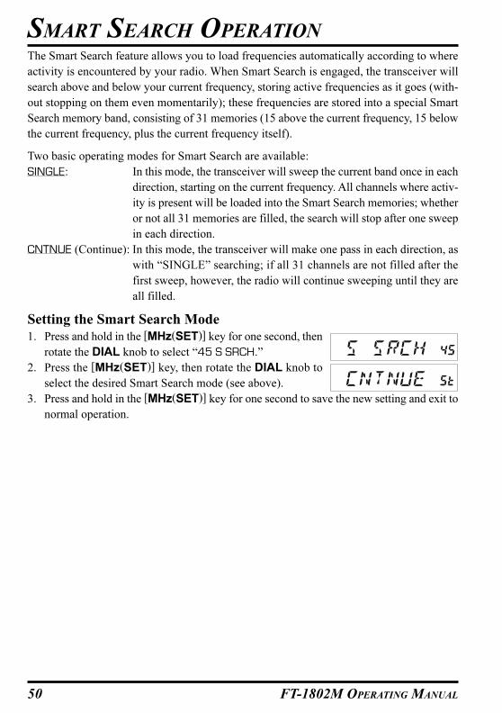
50 FT-1802M OPERATING MANUAL
SMART SEARCH OPERATION
The Smart Search feature allows you to load frequencies automatically according to where
activity is encountered by your radio. When Smart Search is engaged, the transceiver will
search above and below your current frequency, storing active frequencies as it goes (with-
out stopping on them even momentarily); these frequencies are stored into a special Smart
Search memory band, consisting of 31 memories (15 above the current frequency, 15 below
the current frequency, plus the current frequency itself).
Two basic operating modes for Smart Search are available:
SINGLE: In this mode, the transceiver will sweep the current band once in each
direction, starting on the current frequency. All channels where activ-
ity is present will be loaded into the Smart Search memories; whether
or not all 31 memories are filled, the search will stop after one sweep
in each direction.
CNTNUE (Continue): In this mode, the transceiver will make one pass in each direction, as
with “SINGLE” searching; if all 31 channels are not filled after the
first sweep, however, the radio will continue sweeping until they are
all filled.
Setting the Smart Search Mode
1. Press and hold in the [MHz(SET)] key for one second, then
rotate the DIAL knob to select “45 S SRCH.”
2. Press the [MHz(SET)] key, then rotate the DIAL knob to
select the desired Smart Search mode (see above).
3. Press and hold in the [MHz(SET)] key for one second to save the new setting and exit to
normal operation.
51FT-1802M OPERATING MANUAL
SMART SEARCH OPERATION
Storing Smart Search Memories
1. Set the radio to the VFO mode. Be sure that you have the Squelch adjusted properly (so
that band noise is quieted).
2. Press the Microphone’s [P2] key to enter the Smart Search
mode. The “S SRCH” notation will appear on the display
for two seconds.
3. Press the [MHz(SET)] key (or Microphone’s [A] key) to begin Smart Search scanning.
4. As active channels are detected, they will automatically be stored into the Smart Search
memory bank without causing the sweep to halt.
5. Depending on the mode you set for Smart Search operation (“SINGLE” or “CNTNUE”),
the Smart Search scan will eventually terminate, and the LCD will revert to Smart Search
Memory Channel “C.”
6. To recall the Smart Search memories, just rotate the DIAL knob to choose from among
the Smart Search memories.
7. To return to normal operation, press the [D/MR(MW)] key.
Smart Search is a great tool when visiting a city for the first time. You don’t need
to spend hours looking up repeater frequencies from a reference guidebook; just
ask your FT-1802M where the action is!
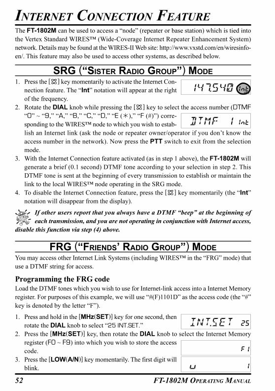
52 FT-1802M OPERATING MANUAL
The FT-1802M can be used to access a “node” (repeater or base station) which is tied into
the Vertex Standard WIRES™ (Wide-Coverage Internet Repeater Enhancement System)
network. Details may be found at the WIRES-II Web site: http://www.vxstd.com/en/wiresinfo-
en/. This feature may also be used to access other systems, as described below.
SRG (“SISTER RADIO GROUP”) MODE
1. Press the [ ] key momentarily to activate the Internet Con-
nection feature. The “Int” notation will appear at the right
of the frequency.
2. Rotate the DIAL knob while pressing the [ ] key to select the access number (DTMF
“0” ~ “9,” “A,” “B,” “C,” “D,” “E (�),” “F (#)”) corre-
sponding to the WIRES™ node to which you wish to estab-
lish an Internet link (ask the node or repeater owner/operator if you don’t know the
access number in the network). Now press the PTT switch to exit from the selection
mode.
3. With the Internet Connection feature activated (as in step 1 above), the FT-1802M will
generate a brief (0.1 second) DTMF tone according to your selection in step 2. This
DTMF tone is sent at the beginning of every transmission to establish or maintain the
link to the local WIRES™ node operating in the SRG mode.
4. To disable the Internet Connection feature, press the [ ] key momentarily (the “Int”
notation will disappear from the display).
If other users report that you always have a DTMF “beep” at the beginning of
each transmission, and you are not operating in conjunction with Internet access,
disable this function via step (4) above.
FRG (“FRIENDS’ RADIO GROUP”) MODE
You may access other Internet Link Systems (including WIRES™ in the “FRG” mode) that
use a DTMF string for access.
Programming the FRG code
Load the DTMF tones which you wish to use for Internet-link access into a Internet Memory
register. For purposes of this example, we will use “#(F)1101D” as the access code (the “#”
key is denoted by the letter “F”).
1. Press and hold in the [MHz(SET)] key for one second, then
rotate the DIAL knob to select “25 INT.SET.”
2. Press the [MHz(SET)] key, then rotate the DIAL knob to select the Internet Memory
register (F0 ~ F9) into which you wish to store the access
code.
3. Press the [LOW(A/N)] key momentarily. The first digit will
blink.
INTERNET CONNECTION FEATURE

53FT-1802M OPERATING MANUAL
4. Rotate the DIAL knob to select “F” (representing DTMF
“#”: the first digit of the DTMF string).
5. Press the [LOW(A/N)] key momentarily to accept the first digit and move to the second
digit of the DTMF string.
6. Repeat the previous steps until you have completed the ac-
cess code (“#(F)1101D”).
7. If you wish to attach an alpha/numeric name “Tag” to the Internet Memory, proceed to
the next step; otherwise press and hold in the [MHz(SET)] key for one second to save
the setting.
8. Press the [MHz(SET)] key twice to enable programming of the name tag (the Internet
Memory register number will blink).
9. Press the [D/MR(MW)] key momentarily. The “- -ALPHA- -”
notation will appear on the display for 2 seconds, then the
Memory register number will blink again.
10. Press the [MHz(SET)] key momentarily. The first digit will blink.
11. Rotate the DIAL knob to select the first digit of the desired
label.
12. Press the [LOW(A/N)] key to move to the next character.
13. If you make a mistake, press the [REV(DW)] key to back-space the cursor, then re-enter
the correct letter, number, or symbol.
14. Repeat steps 11 and 12 to program the remaining letters,
numbers, or symbols of the desired label. A total of six char-
acters may be used in the creation of a label.
15. When you have finished programming the label (6 characters or less), press and hold in
the [MHz(SET)] key for one second to confirm the label.
16. Repeat steps 1 through 15 to store other access codes, if so desired.
17. Press the PTT switch to save the setting and exit to normal operation.
Operation (Accessing an FRG Node)
1. Press and hold in the [MHz(SET)] key for one second, then
rotate the DIAL knob to select “23 INT MD.”
2. Press the [MHz(SET)] key, then rotate the DIAL knob to set this Set Mode Item to
“FRG” (thus activating the “Other Internet Link System”
mode).
3. Press and hold in the [MHz(SET)] key for one second to save the new setting.
4. Press the [ ] key momentarily to activate the Internet Con-
nection feature. The “Int” notation will appear at the right
of the frequency.
5. Rotate the DIAL knob while pressing the [ ] key to select the Internet Memory register
INTERNET CONNECTION FEATURE
FRG (“FRIENDS’ RADIO GROUP”) MODE

54 FT-1802M OPERATING MANUAL
number (F0 ~ F9) (or Name) corresponding to the Internet
link repeater to which you wish to establish an Internet link,
then press the PTT switch momentarily to lock in the selected access number.
6. Once the Internet Connection feature is activated per step 4 above, you may now press
the [ ] key, while you are transmitting, to send out the selected DTMF string (to estab-
lish the link to the desired Internet-link mode).
7. To return to the WIRES™ mode, repeat steps 1 - 3 above, selecting “SRG” in step 2.
INTERNET CONNECTION FEATURE
FRG (“FRIENDS’ RADIO GROUP”) MODE
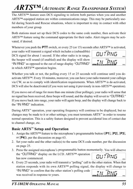
55FT-1802M OPERATING MANUAL
The ARTS™ feature uses DCS signaling to inform both parties when you and another
ARTS™-equipped station are within communications range. This may be particularly use-
ful during Search-and Rescue situations, where is important to stay in contact with other
members of your group.
Both stations must set up their DCS codes to the same code number, then activate their
ARTS™ feature using the command appropriate for their radio. Alert ringers may be acti-
vated, if desired.
Whenever you push the PTT switch, or every 25 (or 15) seconds after ARTS™ is activated,
your radio will transmit a signal which includes a (subaudible)
DCS signal for about 1 second. If the other radio is in range,
the beeper will sound (if enabled) and the display will show
“IN RNG” as opposed to the out of range display “OUTRNG”
in which ARTS™ operation begins.
Whether you talk or not, the polling every 15 or 25 seconds will continue until you de-
activate ARTS™. Every 10 minutes, moreover, you can have your radio transmit your callsign
via CW, so as to comply with identification requirements. When ARTS™ is de-activated,
DCS will also be deactivated (if you were not using it previously in non-ARTS™ operation).
If you move out of range for more than one minute (four pollings), your radio will sense that
no signal has been received, three beeps will sound, and the display will revert to “OUTRNG.”
If you move back into range, your radio will again beep, and the display will change back to
the “IN RNG” indication.
During ARTS™ operation, your operating frequency will continue to be displayed, but no
changes may be made to it or other settings; you must terminate ARTS™ in order to resume
normal operation. This is a safety feature designed to prevent accidental loss of contact due
to channel change, etc.
Basic ARTS™ Setup and Operation
1. Assign the ARTS™ feature to the microphone’s programmable button ([P1], [P2], [P3],
or [P4]), per the discussion on page 63.
2. Set your radio and the other radio(s) to the same DCS code number, per the discussion
on page 25.
3. Press the assigned microphone’s programmable button momentarily. You will observe
the “OUTRNG” display on the LCD. ARTS™ operation
has now commenced.
4. Every 25 seconds, your radio will transmit a “polling” call to the other station. When that
station responds with its own ARTS™ polling signal, the display will change to
“IN RNG” to confirm that the other station’s polling code
was received in response to yours.
ARTS™ (AUTOMATIC RANGE TRANSPONDER SYSTEM)

56 FT-1802M OPERATING MANUAL
5. Press the assigned microphone’s programmable button momentarily to exit ARTS™
operation and resume normal functioning of the transceiver.
ARTS™ Polling Time Options
The ARTS™ feature may be programmed to poll every 25 seconds (default value) or 15
seconds. The default value provides maximum battery conservation, because the polling
signal is sent out less frequently. To change the polling interval:
1. Press and hold in the [MHz(SET)] key for one second, then
rotate the DIAL knob to select “3 AR INT.”
2. Press the [MHz(SET)] key, then rotate the DIAL knob to
select the desired polling interval (15 or 25 seconds).
3. When you have made your selection, press and hold in the [MHz(SET)] key for one
second to save the new setting and exit to normal operation.
ARTS™ Alert Beep Options
The ARTS™ feature allows two kinds of alert beeps (with the additional option of turning
them off), so as to alert you to the current status of ARTS™ operation. Depending on your
location and the potential annoyance associated with frequent beeps, you may choose the
Beep mode which best suits your needs. The choices are:
IN RNG: The beeps are issued only when the radio first confirms that you are within
range, but does not re-confirm with beeps thereafter.
ALWAYS: Every time a polling transmission is received from the other station, the alert
beeps will be heard.
OFF: No alert beeps will be heard; you must look at the display to confirm current
ARTS™ status.
To set the ARTS™ Beep mode, use the following procedure:
1. Press and hold in the [MHz(SET)] key for one second, then
rotate the DIAL knob to select “2 AR BEP.”
2. Press the [MHz(SET)] key, then rotate the DIAL knob to
select the desired ARTS™ Beep mode (see above).
3. When you have made your selection, press and hold in the [MHz(SET)] key for one
second to save the new setting and exit to normal operation.
ARTS™ (AUTOMATIC RANGE TRANSPONDER SYSTEM)

57FT-1802M OPERATING MANUAL
CW Identifier Setup
The ARTS™ feature includes a CW identifier, as discussed previously. Every ten minutes
during ARTS™ operation, the radio can be instructed to send “DE (your callsign) K,” if this
feature is enabled. The callsign field may contain up to 16 characters.
Here’s how to program the CW Identifier:
1. Press and hold in the [MHz(SET)] key for one second, then
rotate the DIAL knob to select “11 CW ID.”
2. Press the [MHz(SET)] key, followed by the [LOW(A/N)] key, to display any previ-
ously-stored callsign.
3. Press and hold in the [LOW(A/N)] key for one second to
Clear any previous callsign.
4. Rotate the DIAL knob to select the first letter/number of
your callsign, then press the [LOW(A/N)] key momentarily
to save the first letter/number and move on to the next character.
5. Repeat the previous step, as many times as necessary, to complete your callsign. Note
that the “slant bar” (– • • – •) is among the available charac-
ters, should you be a “portable” station.
6. If you make a mistake, press the [REV(DW)] key to move back to the previous letter/
number’s slot, then re-select the correct letter/number.
7. When you have finished entering your entire callsign and it contains less than 16 charac-
ters, press the [MHz(SET)] key momentarily to confirm the callsign. (if you callsign has
exactly 16 characters, you do not need to press the [MHz(SET)] key in this step, and
step ).
8. Press the [MHz(SET)] key momentarily again, then rotate
the DIAL knob to set this Item to “ON” (to enable the CW
ID function).
9. When you have made your selection, press and hold in the [MHz(SET)] key for one
second to save the new setting and exit to normal operation.
To disable the CW Identifier:
1. Press and hold in the [MHz(SET)] key for one second, then
rotate the DIAL knob to select “11 CW ID.”
2. Press the [MHz(SET)] key momentarily, then rotate the
DIAL knob to set this Item to “OFF” (to disable the CW ID
function).
3. When you have made your selection, press and hold in the [MHz(SET)] key for one
second to save the new setting and exit to normal operation.
You may check your work by monitoring the entered callsign. To do this, recall Set
Mode Item “11 CW ID” and press the [MHz(SET)] key, then press the [D/MR(MW)]
key.
ARTS™ (AUTOMATIC RANGE TRANSPONDER SYSTEM)

58 FT-1802M OPERATING MANUAL
CW TRAINING FEATURE
The FT-1802M provides a CW Training feature, which sends random Morse Code via the
sidetone (heard in the speaker), so you can improve your CW proficiency.
1. Press and hold in the [MHz(SET)] key for one second, then
rotate the DIAL knob to select “12 CWTRNG.”
2. Press the [MHz(SET)] key momentarily to enable adjust-
ment of this Set Mode Item.
3. Press the [LOW(A/N)] key to select the Training mode (displayed in fine print at the
upper edge of the LCD):
1A: Sends five Alphabet characters only
A: Sends Alphabet characters only (Repeatedly)
1n: Sends five Numeric characters only
n: Sends Numeric characters only (Repeatedly)
1An:Sends five Alphabet, Numeric, “?,” and “/” characters (Mixed)
An: Send Alphabet, Numeric, “?,” and “/” characters (Mixed, Continuously in group
of five)
4. Rotate the DIAL knob to select the Morse speed. You may select the units of the code
speed between “WPM (Words per minute)” and “CPM:
characters per minute)” by pressing the [D/MR(MW)] key.
5. Press the [REV(DW)] key to begin generation of the code characters (CW sidetone only,
the radio does not transmit); the transmitted characters will
appear on the display. If one of the “1” modes is selected in
step 3 above, press the [REV(DW)] key to send another code group.
6. To disable the CW Training feature, press the [MHz(SET)] key momentarily.
7. Press and hold in the [MHz(SET)] key for one second to exit to normal operation.
The “CPM” selection is based on the international “PARIS” standard, which stipu-
lates five characters per word.

59FT-1802M OPERATING MANUAL
The FT-1802M may be used for 1200 bps Packet operation, using most all commonly-
available Terminal Node Controllers (TNCs). Connections between the transceiver and the
TNC are accomplished via the front panel Microphone connector and rear panel External
Speaker jack, per the diagram below.
The audio level from the receiver to the TNC may be adjusted by using the VOL knob, as
with voice operation. The input level to the FT-1802M from the TNC may be adjusted via
Set Mode Item “27 MCGAIN;” see page 64 for details.
Be sure to turn the transceiver and TNC off before connecting the cables, so as to prevent
voltage spikes from possibly damaging your transceiver.
Remember to readjust the default microphone input level to “LVL 5” (Set Mode Item “27
MCGAIN”) when Packet operation is finished.
PACKET OPERATION
Pin 4: GNDPin 5: PACKET TX INPin 6: PTT
PACKET RX OUT
EXT SP REAR PANEL( )MIC ( )
DATA
OUT
DATA
IN PTT

60 FT-1802M OPERATING MANUAL
PASSWORD
The FT-1802M provides a password feature which can minimize the chance that your trans-
ceiver could be used by an unauthorized party.
When the password feature is activated, the radio will ask for the four digit password to be
entered when the radio is first turned on. You must enter the four digit password from the
Microphone’s keypad. If the wrong password is entered, the microprocessor will shut down
the radio automatically.
To enter the password and activating this feature, use the following procedure:
1. Press and hold in the [MHz(SET)] key for one second, then
rotate the DIAL knob to select “40 PSWD.”
2. Press the [MHz(SET)] key momentarily to enable adjust-
ment of this Set Mode Item.
3. Press the [LOW(A/N)] key momentarily to display any pre-
viously-stored password.
4. Rotate the DIAL knob to select the first digit of the desired
number/letter (0-9, A, B, C, D, E (substitute for “�”), and F
(substitute for “#”).
5. Press the [LOW(A/N)] key to move to the next digit.
6. Repeat steps 4 and 5 to program the remaining numbers/
letters of the desired password.
7. If you make a mistake, press the [REV(DW)] key to move back to the previous digit,
then re-select the correct number/letter.
8. When you have finished entering the password, press and hold in the [MHz(SET)] key
for one second to save the new setting and exit to normal operation.
9. If you wish to disable the Password feature, repeat steps 1 and 2 above, now rotate the
DIAL knob to select “OFF,” then press and hold in the [MHz(SET)] key for one second.
1) We recommend that you to write down the password number, and keep it in a
safe place you can easily find if you forget your password.
2) If you forget the password number, you may turn on the transceiver by performing the
“Microprocessor Resetting” procedure (see page 66). However, the FT-1802M will clear
the password, as well as all memories, and will restore all other settings to factory de-
faults.
MISCELLANEOUS SETTINGS

61FT-1802M OPERATING MANUAL
TIME-OUT TIMER (TOT)The “Time-Out Timer” (TOT) feature is designed to force the transceiver into the “receive”
mode after a preset time period of continuous transmission (the default is 3 minutes). This
feature prevents your transceiver from transmitting a “dead carrier” for a long period of time
in the event that the microphone PTT switch is accidentally locked in the “TX” condition.
The Time-Out Timer’s “switch-to-receive” time may be adjusted to 1/3/5/10 minutes, or
Off.
To change the default (3 minutes) time setting:
1. Press and hold in the [MHz(SET)] key for one second, then
rotate the DIAL knob to select “53 TOT.”
2. Press the [MHz(SET)] key, then rotate the DIAL knob to
select the desired interval (1/3/5/10 minutes), or OFF.
3. Press and hold in the [MHz(SET)] key for one second to save the new setting and exit to
normal operation.
When your transmission time is within 10 seconds of the Time-Out Timer expira-
tion, an Alert bell will provide an audible warning from the speaker.
AUTOMATIC POWER-OFF (APO)The “Automatic Power-Off” (APO) feature will turn the radio completely off after a user-
defined period of PTT or key/button inactivity. If you do not press any front panel keys or
buttons, rotate the DIAL knob, use the microphone’s keys and buttons, or transmit, and so
long as the transceiver is not scanning or engaged in priority monitoring, the radio will shut
itself off after the specified time period. The available selections for the time before power-
off are 0.5/1/3/5/8 hours, as well as APO Off. This feature is useful in minimizing battery
drain in a mobile installation if you forget to turn the transceiver off when you leave your
vehicle.
To activate the APO feature:
1. Press and hold in the [MHz(SET)] key for one second, then
rotate the DIAL knob to select “1 APO.”
2. Press the [MHz(SET)] key, then rotate the DIAL knob to
select the desired “switch-off” time or OFF.
3. Press and hold in the [MHz(SET)] key for one second to save the new setting and exit to
normal operation.
If there is no action by you within the time interval programmed, an Alert bell will provide
an audible warning from the speaker within 1 minute of the APO Timer expiration, then the
microprocessor will shut down the radio automatically.
MISCELLANEOUS SETTINGS

62 FT-1802M OPERATING MANUAL
BUSY CHANNEL LOCK-OUT (BCLO)The BCLO feature prevents the radio’s transmitter from being activated if a signal strong
enough to break through the “noise” squelch is present. On a frequency where stations using
different CTCSS or DCS codes may be active, BCLO prevents you from disrupting their
communications accidentally (because your radio may be muted by its own Tone Decoder).
The default setting for the BCLO is OFF, and here is how to change that setting:
1. Press and hold in the [MHz(SET)] key for one second, then
rotate the DIAL knob to select “5 BCLO.”
2. Press the [MHz(SET)] key momentarily to enable adjustment of this Set Mode Item.
3. Rotate the DIAL knob to set this Set Mode Item to “ON”
(thus activating the BCLO feature).
4. When you have made your selection, press and hold in the [MHz(SET)] key for one
second to save the new setting and exit to normal operation.
Remember that BCLO is controlled by the Noise Squelch; if you have DCS or
TSQ engaged, BCLO will inhibit transmission if a station is on frequency but not
transmitting the proper tone; BCLO will thus prevent you from interfering with the other
station’s transmission.
MISCELLANEOUS SETTINGS

63FT-1802M OPERATING MANUAL
MISCELLANEOUS SETTINGS
PROGRAMMING THE KEY ASSIGNMENTS
Default FT-1802M key functions have been assigned to the Microphone’s [P1]/[P2]/[P3]/
[P4] buttons at the factory. These may be changed by the user, if you wish to assign quick
access to another function.
To change the assignments for the programmable keys:
1. Press and hold in the [MHz(SET)] key for one second, then
rotate the DIAL knob to select the Menu Item to be config-
ured (“36 PRG P1,” “37 PRG P2,” “38 PRG P3,” or “39 PRG P4”).
2. Press the [MHz(SET)] key, then rotate the DIAL knob to select the function you wish to
assign to the button you selected in the previous step. The available choices are vary
slightly among the four keys you may program, and they
include:
ARTS: Engages the ARTS™ operation.
SQLOFF: Opens the Squelch to allow un-muted reception.
WX CH: Switches operation to the Weather channels bank.
S SRCH: Engages the Smart Search operation.
C SRCH: Engages the Tone Search Scanning feature.
SCAN: Engages the Scan operation
T CALL: Activates 1750 Hz Tone Burst
or one of the Set Menu items.
3. Press the [MHz(SET)] key momentarily to save the new setting, then rotate the DIAL
knob to select another programmable button to modify, if desired, and repeat the above
steps.
4. Press and hold in the [MHz(SET)] key for one second to exit to normal operation.
You may assign Set Mode items to the Microphone’s [P1]/[P2]/[P3]/[P4] buttons, as well,
to do this:
1. Press and hold in the [MHz(SET)] key for one second to enter the Set mode.
2. Rotate the DIAL knob to select the Set Mode Item which you wish to assign to the key as
a Menu short-cut.
3. Press and hold in the Microphone’s [P1], [P2], [P3], or [P4] button for one second to
assign the Set Mode Item to that button.
4. Now you can recall this preferred Set Mode Item by simply pressing the Microphone’s
button momentarily.
Button
[P1]
[P2]
[P3]
[P4]
Default
SQLOFF
S SRCH
C SRCH
USA Version: WX CH
EXP Version: T.CALL
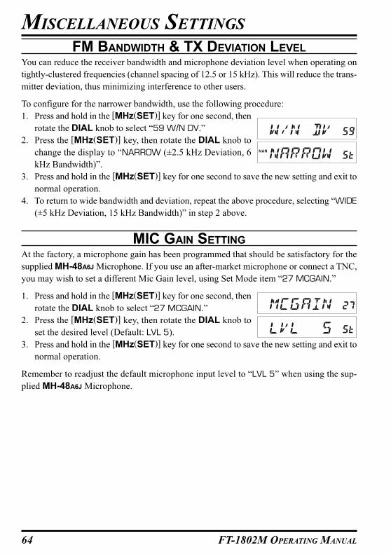
64 FT-1802M OPERATING MANUAL
FM BANDWIDTH & TX DEVIATION LEVEL
You can reduce the receiver bandwidth and microphone deviation level when operating on
tightly-clustered frequencies (channel spacing of 12.5 or 15 kHz). This will reduce the trans-
mitter deviation, thus minimizing interference to other users.
To configure for the narrower bandwidth, use the following procedure:
1. Press and hold in the [MHz(SET)] key for one second, then
rotate the DIAL knob to select “59 W/N DV.”
2. Press the [MHz(SET)] key, then rotate the DIAL knob to
change the display to “NARROW (±2.5 kHz Deviation, 6
kHz Bandwidth)”.
3. Press and hold in the [MHz(SET)] key for one second to save the new setting and exit to
normal operation.
4. To return to wide bandwidth and deviation, repeat the above procedure, selecting “WIDE
(±5 kHz Deviation, 15 kHz Bandwidth)” in step 2 above.
MIC GAIN SETTING
At the factory, a microphone gain has been programmed that should be satisfactory for the
supplied MH-48A6J Microphone. If you use an after-market microphone or connect a TNC,
you may wish to set a different Mic Gain level, using Set Mode item “27 MCGAIN.”
1. Press and hold in the [MHz(SET)] key for one second, then
rotate the DIAL knob to select “27 MCGAIN.”
2. Press the [MHz(SET)] key, then rotate the DIAL knob to
set the desired level (Default: LVL 5).
3. Press and hold in the [MHz(SET)] key for one second to save the new setting and exit to
normal operation.
Remember to readjust the default microphone input level to “LVL 5” when using the sup-
plied MH-48A6J Microphone.
MISCELLANEOUS SETTINGS

65FT-1802M OPERATING MANUAL
DCS CODE INVERSION
The DCS system was first introduced in the commercial LMR (Land Mobile Radio) service,
where it is now in widespread use. DCS is sometime referred to by its different proprietary
names, such as DPL® (Digital Private Line®, a registered trademark of Motorola, Inc.).
DCS uses a codeword consisting of a 23-bit frame, transmitted (subaudible) at a data rate of
134.4 bps (bit/sec). Occasionally, signal inversion can result in the complement of a code to
be sent or received. This prevents the receiver’s squelch from opening with DCS enabled, as
the decoded bit sequence would not match that selected for operation.
Typical situations that might cause inversion to occur are:
� Connection of an external receiver preamplifier.
� Operating through a repeater.
� Connection of an external linear amplifier.
Note that code inversion does not mean that any of the above listed equipment is defective!
In certain amplifier configurations, the output signal (phase) is inverted from the input.
Small signal or power amplifiers having an odd number (1, 3, 5, etc.) of amplification stages
may result in inversion of a transmitted or received DCS code.
While under most circumstances this should not occur (amplifier designs and industry stan-
dards take this into account), if you find that your receiver squelch does not open when both
you and the other station are using a common DCS code, you or the other station (but not
both) can try the following:
1. Press and hold in the [MHz(SET)] key for one second, then
rotate the DIAL knob to select “15 DCS RV.”
2. Press the [MHz(SET)] key momentarily, then rotate the
DIAL knob to set this Set Mode Item to “ENABLE” (thus
inverting the DCS Code).
3. When you have made your selection, press and hold the [MHz(SET)] key for one sec-
ond to save the new setting and exit to normal operation.
4. Remember to restore the default setting to “DISABLE” when done.
MISCELLANEOUS SETTINGS

66 FT-1802M OPERATING MANUAL
In some instances of erratic or unpredictable operation, the cause may be corruption of data
in the microprocessor (due to static electricity, etc.). If this happens, resetting of the micro-
processor may restore normal operation. Note that all memories will be erased if you do a
complete microprocessor reset, as described below.
MICROPROCESSOR RESETTING
To clear all memories and other settings to factory defaults:
1. Turn the radio off.
2. Press and hold in the [REV(DW)], [LOW(A/N)], and [D/MR(MW)] keys while turning
the radio on. The “ALL RESET PUSH D/MR KEY” notation will scroll on the display.
3. Press the [D/MR(MW)] key momentarily to reset all settings to their factory defaults
(press any other key to cancel the Reset procedure).
SET MODE RESETTING
To reset the Set (Menu) mode settings to their factory defaults, while leaving other settings
unchanged:
1. Turn the radio off.
2. Press and hold in the [LOW(A/N)] and [D/MR(MW)] keys while turning the radio on.
The “SET MODE RESET PUSH D/MR KEY” notation will scroll on the display.
3. Press the [D/MR(MW)] key momentarily to reset the Set (Menu) mode settings to their
factory defaults (press any other key to cancel the Reset procedure).
RESET PROCEDURE
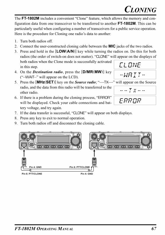
67FT-1802M OPERATING MANUAL
The FT-1802M includes a convenient “Clone” feature, which allows the memory and con-
figuration data from one transceiver to be transferred to another FT-1802M. This can be
particularly useful when configuring a number of transceivers for a public service operation.
Here is the procedure for Cloning one radio’s data to another:
1. Turn both radios off.
2. Connect the user-constructed cloning cable between the MIC jacks of the two radios.
3. Press and hold in the [LOW(A/N)] key while turning the radios on. Do this for both
radios (the order of switch-on does not matter). “CLONE” will appear on the displays of
both radios when the Clone mode is successfully activated
in this step.
4. On the Destination radio, press the [D/MR(MW)] key
(“- -WAIT- -” will appear on the LCD).
5. Press the [MHz(SET)] key on the Source radio; “- - - -TX- - - -” will appear on the Source
radio, and the data from this radio will be transferred to the
other radio.
6. If there is a problem during the cloning process, “ERROR”
will be displayed. Check your cable connections and bat-
tery voltage, and try again.
7. If the data transfer is successful, “CLONE” will appear on both displays.
8. Press any key to exit to normal operation.
9. Turn both radios off and disconnect the cloning cable.
CLONING
Pin 6: PTT/CLONE
Pin 6: PTT/CLONEPin 4: GND
Pin 4: GND
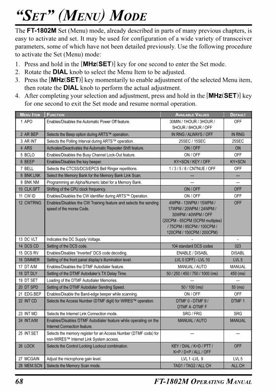
68 FT-1802M OPERATING MANUAL
The FT-1802M Set (Menu) mode, already described in parts of many previous chapters, is
easy to activate and set. It may be used for configuration of a wide variety of transceiver
parameters, some of which have not been detailed previously. Use the following procedure
to activate the Set (Menu) mode:
1. Press and hold in the [MHz(SET)] key for one second to enter the Set mode.
2. Rotate the DIAL knob to select the Menu Item to be adjusted.
3. Press the [MHz(SET)] key momentarily to enable adjustment of the selected Menu item,
then rotate the DIAL knob to perform the actual adjustment.
4. After completing your selection and adjustment, press and hold in the [MHz(SET)] key
for one second to exit the Set mode and resume normal operation.
“SET” (MENU) MODE
MENU ITEM
1 APO
2 AR BEP
3 AR INT
4 ARS
5 BCLO
6 BEEP
7 BELL
8 BNK.LNK
9 BNK NM
10 CLK.SFT
11 CW ID
12 CWTRNG
13 DC VLT
14 DCS CD
15 DCS RV
16 DIMMER
17 DT A/M
18 DT DLY
19 DT SET
20 DT SPD
21 EDG.BEP
22 INT CD
23 INT MD
24 INT.A/M
25 INT.SET
26 LOCK
27 MCGAIN
28 MEM.SCN
AVAILABLE VALUES
30MIN / 1HOUR / 3HOUR /
5HOUR / 8HOUR / OFF
IN RNG / ALWAYS / OFF
25SEC / 15SEC
ON / OFF
ON / OFF
KY+SCN / KEY / OFF
1 / 3 / 5 / 8 / CNTNUE / OFF
---
---
ON / OFF
ON / OFF
4WPM - 13WPM / 15WPM /
17WPM / 20WPM / 24WPM /
30WPM / 40WPM / OFF
(20CPM - 65CPM (5CPM multiples)
/ 75CPM / 85CPM / 100CPM /
120CPM / 150CPM / 200CPM)
-
104 standard DCS codes
ENABLE / DISABL
LVL 0 (OFF) - LVL 10
MANUAL / AUTO
50 / 250 / 450 / 750 / 1000 (ms)
---
50 / 100 (ms)
ON / OFF
DTMF 0 - DTMF 9 /
DTMF A -DTMF F
SRG / FRG
MANUAL / AUTO
---
KEY / DIAL / K+D / PTT /
K+P / D+P / ALL / OFF
LVL 1 -LVL 9
TAG1 / TAG2 / ALL CH
FUNCTION
Enables/Disables the Automatic Power Off feature.
Selects the Beep option during ARTS™ operation.
Selects the Polling Interval during ARTS™ operation.
Activates/Deactivates the Automatic Repeater Shift feature.
Enables/Disables the Busy Channel Lock-Out feature.
Enables/Disables the key beeper.
Selects the CTCSS/DCS/EPCS Bell Ringer repetitions.
Select the Memory Bank for the Memory Bank Link Scan.
Programming an Alpha/Numeric label for a Memory Bank.
Shifting of the CPU clock frequency.
Enables/Disables the CW identifier during ARTS™ Operation.
Enables/Disables the CW Training feature and selects the sending
speed of the morse Code.
Indicates the DC Supply Voltage.
Setting of the DCS code.
Enables/Disables “Inverted” DCS code decoding.
Setting of the front panel display’s illumination level.
Enables/Disables the DTMF Autodialer feature.
Setting of the DTMF Autodialer’s TX Delay Time.
Loading of the DTMF Autodialer Memories.
Setting of the DTMF Autodialer Sending Speed.
Enables/Disable the Band-edge beeper while scanning.
Selects the Access Number (DTMF digit) for WIRES™ operation.
Selects the Internet Link Connection mode.
Enables/Disables DTMF Autodialer feature while operating on the
Internet Connection feature.
Selects the memory register for an Access Number (DTMF code) for
non-WIRES™ Internet Link System access.
Selects the Control Locking Lockout combination.
Adjust the microphone gain level.
Selects the Memory Scan mode.
DEFAULT
OFF
IN RNG
25SEC
ON
OFF
KY+SCN
OFF
---
---
OFF
OFF
OFF
-
023
DISABL
LVL 5
MANUAL
450 (ms)
---
50 (ms)
OFF
DTMF 1
SRG
MANUAL
---
OFF
LVL 5
ALL CH
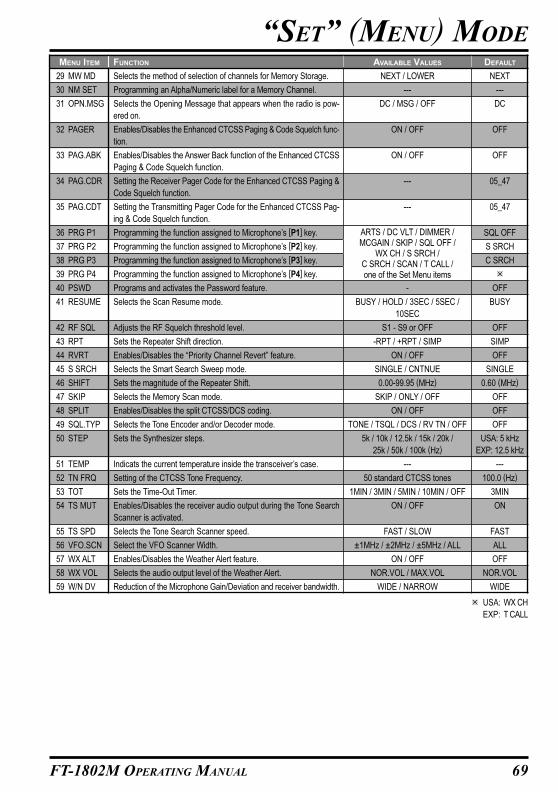
69FT-1802M OPERATING MANUAL
“SET” (MENU) MODE
MENU ITEM
29 MW MD
30 NM SET
31 OPN.MSG
32 PAGER
33 PAG.ABK
34 PAG.CDR
35 PAG.CDT
36 PRG P1
37 PRG P2
38 PRG P3
39 PRG P4
40 PSWD
41 RESUME
42 RF SQL
43 RPT
44 RVRT
45 S SRCH
46 SHIFT
47 SKIP
48 SPLIT
49 SQL.TYP
50 STEP
51 TEMP
52 TN FRQ
53 TOT
54 TS MUT
55 TS SPD
56 VFO.SCN
57 WX ALT
58 WX VOL
59 W/N DV
FUNCTION
Selects the method of selection of channels for Memory Storage.
Programming an Alpha/Numeric label for a Memory Channel.
Selects the Opening Message that appears when the radio is pow-
ered on.
Enables/Disables the Enhanced CTCSS Paging & Code Squelch func-
tion.
Enables/Disables the Answer Back function of the Enhanced CTCSS
Paging & Code Squelch function.
Setting the Receiver Pager Code for the Enhanced CTCSS Paging &
Code Squelch function.
Setting the Transmitting Pager Code for the Enhanced CTCSS Pag-
ing & Code Squelch function.
Programming the function assigned to Microphone’s [P1] key.
Programming the function assigned to Microphone’s [P2] key.
Programming the function assigned to Microphone’s [P3] key.
Programming the function assigned to Microphone’s [P4] key.
Programs and activates the Password feature.
Selects the Scan Resume mode.
Adjusts the RF Squelch threshold level.
Sets the Repeater Shift direction.
Enables/Disables the “Priority Channel Revert” feature.
Selects the Smart Search Sweep mode.
Sets the magnitude of the Repeater Shift.
Selects the Memory Scan mode.
Enables/Disables the split CTCSS/DCS coding.
Selects the Tone Encoder and/or Decoder mode.
Sets the Synthesizer steps.
Indicats the current temperature inside the transceiver’s case.
Setting of the CTCSS Tone Frequency.
Sets the Time-Out Timer.
Enables/Disables the receiver audio output during the Tone Search
Scanner is activated.
Selects the Tone Search Scanner speed.
Select the VFO Scanner Width.
Enables/Disables the Weather Alert feature.
Selects the audio output level of the Weather Alert.
Reduction of the Microphone Gain/Deviation and receiver bandwidth.
AVAILABLE VALUES
NEXT / LOWER
---
DC / MSG / OFF
ON / OFF
ON / OFF
---
---
-
BUSY / HOLD / 3SEC / 5SEC /
10SEC
S1 - S9 or OFF
-RPT / +RPT / SIMP
ON / OFF
SINGLE / CNTNUE
0.00-99.95 (MHz)
SKIP / ONLY / OFF
ON / OFF
TONE / TSQL / DCS / RV TN / OFF
5k / 10k / 12.5k / 15k / 20k /
25k / 50k / 100k (Hz)
---
50 standard CTCSS tones
1MIN / 3MIN / 5MIN / 10MIN / OFF
ON / OFF
FAST / SLOW
±1MHz / ±2MHz / ±5MHz / ALL
ON / OFF
NOR.VOL / MAX.VOL
WIDE / NARROW
DEFAULT
NEXT
---
DC
OFF
OFF
05_47
05_47
SQL OFF
S SRCH
C SRCH
�
OFF
BUSY
OFF
SIMP
OFF
SINGLE
0.60 (MHz)
OFF
OFF
OFF
USA: 5 kHz
EXP: 12.5 kHz
---
100.0 (Hz)
3MIN
ON
FAST
ALL
OFF
NOR.VOL
WIDE
ARTS / DC VLT / DIMMER /MCGAIN / SKIP / SQL OFF /
WX CH / S SRCH /C SRCH / SCAN / T CALL /one of the Set Menu items
� USA: WX CH
EXP: T CALL
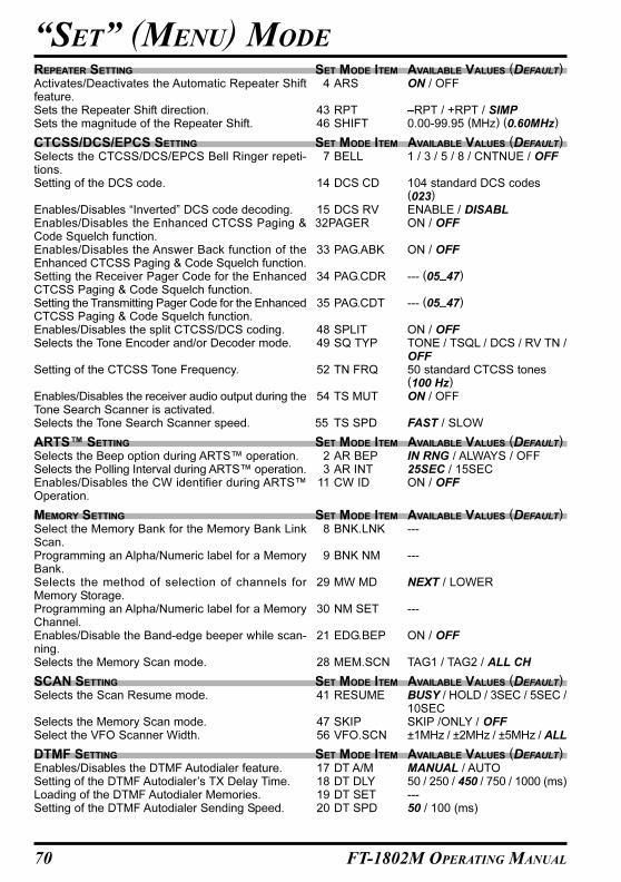
70 FT-1802M OPERATING MANUAL
“SET” (MENU) MODE
REPEATER SETTINGActivates/Deactivates the Automatic Repeater Shiftfeature.Sets the Repeater Shift direction.Sets the magnitude of the Repeater Shift.
CTCSS/DCS/EPCS SETTINGSelects the CTCSS/DCS/EPCS Bell Ringer repeti-tions.Setting of the DCS code.
Enables/Disables “Inverted” DCS code decoding.Enables/Disables the Enhanced CTCSS Paging &Code Squelch function.Enables/Disables the Answer Back function of theEnhanced CTCSS Paging & Code Squelch function.Setting the Receiver Pager Code for the EnhancedCTCSS Paging & Code Squelch function.Setting the Transmitting Pager Code for the EnhancedCTCSS Paging & Code Squelch function.Enables/Disables the split CTCSS/DCS coding.Selects the Tone Encoder and/or Decoder mode.
Setting of the CTCSS Tone Frequency.
Enables/Disables the receiver audio output during theTone Search Scanner is activated.Selects the Tone Search Scanner speed.
ARTS™ SETTINGSelects the Beep option during ARTS™ operation.Selects the Polling Interval during ARTS™ operation.Enables/Disables the CW identifier during ARTS™Operation.
MEMORY SETTINGSelect the Memory Bank for the Memory Bank LinkScan.Programming an Alpha/Numeric label for a MemoryBank.Selects the method of selection of channels forMemory Storage.Programming an Alpha/Numeric label for a MemoryChannel.Enables/Disable the Band-edge beeper while scan-ning.Selects the Memory Scan mode.
SCAN SETTINGSelects the Scan Resume mode.
Selects the Memory Scan mode.Select the VFO Scanner Width.
DTMF SETTINGEnables/Disables the DTMF Autodialer feature.Setting of the DTMF Autodialer’s TX Delay Time.Loading of the DTMF Autodialer Memories.Setting of the DTMF Autodialer Sending Speed.
AVAILABLE VALUES (DEFAULT)ON / OFF
–RPT / +RPT / SIMP0.00-99.95 (MHz) (0.60MHz)
AVAILABLE VALUES (DEFAULT)1 / 3 / 5 / 8 / CNTNUE / OFF
104 standard DCS codes(023)
ENABLE / DISABLON / OFF
ON / OFF
--- (05_47)
--- (05_47)
ON / OFFTONE / TSQL / DCS / RV TN /OFF50 standard CTCSS tones(100 Hz)
ON / OFF
FAST / SLOW
AVAILABLE VALUES (DEFAULT)IN RNG / ALWAYS / OFF25SEC / 15SECON / OFF
AVAILABLE VALUES (DEFAULT)---
---
NEXT / LOWER
---
ON / OFF
TAG1 / TAG2 / ALL CH
AVAILABLE VALUES (DEFAULT)BUSY / HOLD / 3SEC / 5SEC /10SECSKIP /ONLY / OFF±1MHz / ±2MHz / ±5MHz / ALL
AVAILABLE VALUES (DEFAULT)MANUAL / AUTO50 / 250 / 450 / 750 / 1000 (ms)---50 / 100 (ms)
SET MODE ITEM4 ARS
43 RPT46 SHIFT
SET MODE ITEM7 BELL
14 DCS CD
15 DCS RV32PAGER
33 PAG.ABK
34 PAG.CDR
35 PAG.CDT
48 SPLIT49 SQ TYP
52 TN FRQ
54 TS MUT
55 TS SPD
SET MODE ITEM2 AR BEP3 AR INT
11 CW ID
SET MODE ITEM8 BNK.LNK
9 BNK NM
29 MW MD
30 NM SET
21 EDG.BEP
28 MEM.SCN
SET MODE ITEM41 RESUME
47 SKIP56 VFO.SCN
SET MODE ITEM17 DT A/M18 DT DLY19 DT SET20 DT SPD

71FT-1802M OPERATING MANUAL
“SET” (MENU) MODE
WIRES™ SETTINGSelects the Access Number (DTMF digit) forWIRES™ operation.Selects the Internet Link Connection mode.Enables/Disables DTMF Autodialer feature while op-erating on the Internet Connection feature.Selects the memory register for an Access Number(DTMF code) for non-WIRES™ Internet Link Systemaccess.
SWITCH/KNOB SETTINGEnables/Disables the key beeper.Selects the Control Locking Lockout combination.
Programming the function assigned to Microphone’s[P1] key.Programming the function assigned to Microphone’s[P2] key.Programming the function assigned to Microphone’s[P3] key.Programming the function assigned to Microphone’s[P4] key.Sets the Synthesizer steps.
DISPLAY SETTINGIndicates the DC Supply Voltage.Setting of the front panel display’s illumination level.Selects the Opening Message that appears when theradio is powered on.Indicats the current temperature inside thetransceiver’s case.
MISCELLANEOUS SETTINGEnables/Disables the Automatic Power Off feature.
Enables/Disables the Busy Channel Lock-Out feature.Shifting of the CPU clock frequency.Enables/Disables the CW Training feature and se-lects the sending speed of the morse Code.
Adjust the microphone gain level.Programs and activates the Password feature.Adjusts the RF Squelch threshold level.Enables/Disables the “Priority Channel Revert” fea-ture.Selects the Smart Search Sweep mode.Sets the Time-Out Timer.
Enables/Disables the Weather Alert feature.Selects the audio output level of the Weather Alert.Selects Wide (5 kHz) or Narrow (2.5 kHz) TX Devia-tion.
AVAILABLE VALUES (DEFAULT)DTMF 0 - DTMF 9 /DTMF A - DTMF F (DTMF 1)
SRG / FRGMANUAL / AUTO
---
AVAILABLE VALUES (DEFAULT)KY+SCN / KEY / OFFKEY / DIAL / K+D / PTT / K+P /D+P / ALL / OFF� (SQLOFF)
� (S SRCH)
� (C SRCH)
� (USA Version: WX CH)(EXP Version: T.CALL)
5k (USA) /10k / 12.5k (EXP)/15k / 20k / 25k / 50k / 100k (Hz)
AVAILABLE VALUES (DEFAULT)---LVL 0 (OFF) - LVL 10 (LVL 5)
DC / MSG / OFF
-
AVAILABLE VALUES (DEFAULT)30MIN / 1HOUR / 3HOUR /5 HOUR / 8HOUR / OFFON / OFFON / OFF4WPM - 13WPM / 15WPM /17WPM / 20WPM / 24WPM /30WPM / 40WPM / OFF(20CPM - 65CPM (5CPM mul-tiples) / 75CPM / 85CPM /100CPM / 120CPM /150CPM / 200CPM)LVL 1 - LVL 9 (LVL 5)
-S1 - S9 or OFFON / OFFSINGLE / CNTNUE
1MIN / 3MIN / 5MIN / 10MIN /OFFON / OFFNOR.VOL / MAX.VOLWIDE / NARROW
SET MODE ITEM22 INT CD
23 INT MD24 INT.A/M
25 INT.SET
SET MODE ITEM6 BEEP
26 LOCK
36 PRG P1
37 PRG P2
38 PRG P3
39 PRG P4
50 STEP
SET MODE ITEM13 DC VLT16 DIMMER31 OPN.MSG
51 TEMP
SET MODE ITEM1 APO
5 BCLO10 CLK.SFT12 CWTRNG
27 MCGAIN40 PSWD42 RF SQL44 RVRT45 S SRCH
53 TOT
57 WX ALT58 WX VOL59 W/N DV
�: ARTS / DC VLT / DIMMER / MCGAIN / SKIP / SQL OFF / WX CH / S SRCH / C SRCH / SCAN /T CALL / one of the Set Menu items
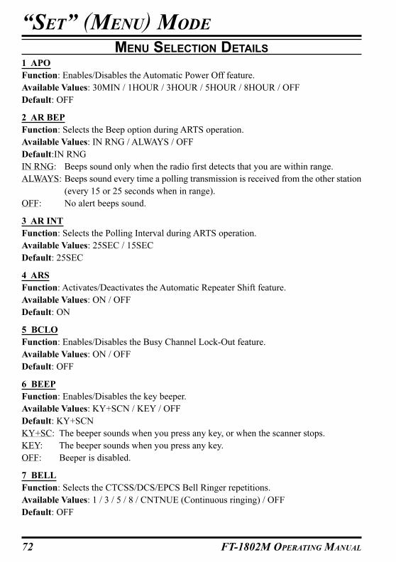
72 FT-1802M OPERATING MANUAL
MENU SELECTION DETAILS
1 APO
Function: Enables/Disables the Automatic Power Off feature.
Available Values: 30MIN / 1HOUR / 3HOUR / 5HOUR / 8HOUR / OFF
Default: OFF
2 AR BEP
Function: Selects the Beep option during ARTS operation.
Available Values: IN RNG / ALWAYS / OFF
Default:IN RNG
IN RNG: Beeps sound only when the radio first detects that you are within range.
ALWAYS: Beeps sound every time a polling transmission is received from the other station
(every 15 or 25 seconds when in range).
OFF: No alert beeps sound.
3 AR INT
Function: Selects the Polling Interval during ARTS operation.
Available Values: 25SEC / 15SEC
Default: 25SEC
4 ARS
Function: Activates/Deactivates the Automatic Repeater Shift feature.
Available Values: ON / OFF
Default: ON
5 BCLO
Function: Enables/Disables the Busy Channel Lock-Out feature.
Available Values: ON / OFF
Default: OFF
6 BEEP
Function: Enables/Disables the key beeper.
Available Values: KY+SCN / KEY / OFF
Default: KY+SCN
KY+SC: The beeper sounds when you press any key, or when the scanner stops.
KEY: The beeper sounds when you press any key.
OFF: Beeper is disabled.
7 BELL
Function: Selects the CTCSS/DCS/EPCS Bell Ringer repetitions.
Available Values: 1 / 3 / 5 / 8 / CNTNUE (Continuous ringing) / OFF
Default: OFF
“SET” (MENU) MODE
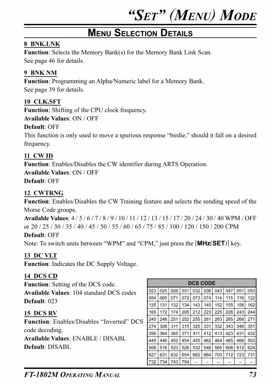
73FT-1802M OPERATING MANUAL
8 BNK.LNK
Function: Selects the Memory Bank(s) for the Memory Bank Link Scan.
See page 46 for details.
9 BNK NM
Function: Programming an Alpha/Numeric label for a Memory Bank.
See page 39 for details.
10 CLK.SFT
Function: Shifting of the CPU clock frequency.
Available Values: ON / OFF
Default: OFF
This function is only used to move a spurious response “birdie,” should it fall on a desired
frequency.
11 CW ID
Function: Enables/Disables the CW identifier during ARTS Operation.
Available Values: ON / OFF
Default: OFF
12 CWTRNG
Function: Enables/Disables the CW Training feature and selects the sending speed of the
Morse Code groups.
Available Values: 4 / 5 / 6 / 7 / 8 / 9 / 10 / 11 / 12 / 13 / 15 / 17 / 20 / 24 / 30 / 40 WPM / OFF
or 20 / 25 / 30 / 35 / 40 / 45 / 50 / 55 / 60 / 65 / 75 / 85 / 100 / 120 / 150 / 200 CPM
Default: OFF
Note: To switch units between “WPM” and “CPM,” just press the [MHz(SET)] key.
13 DC VLT
Function: Indicates the DC Supply Voltage.
14 DCS CD
Function: Setting of the DCS code.
Available Values: 104 standard DCS codes
Default: 023
15 DCS RV
Function: Enables/Disables “Inverted” DCS
code decoding.
Available Values: ENABLE / DISABL
Default: DISABL
“SET” (MENU) MODE
MENU SELECTION DETAILS
DCS CODE
023 025 026 031 032 036 043 047 051 053
054 065 071 072 073 074 114 115 116 122
125 131 132 134 143 145 152 155 156 162
165 172 174 205 212 223 225 226 243 244
245 246 251 252 255 261 263 265 266 271
274 306 311 315 325 331 332 343 346 351
356 364 365 371 411 412 413 423 431 432
445 446 452 454 455 462 464 465 466 503
506 516 523 526 532 546 565 606 612 624
627 631 632 654 662 664 703 712 723 731
732 734 743 754 – – – – – –
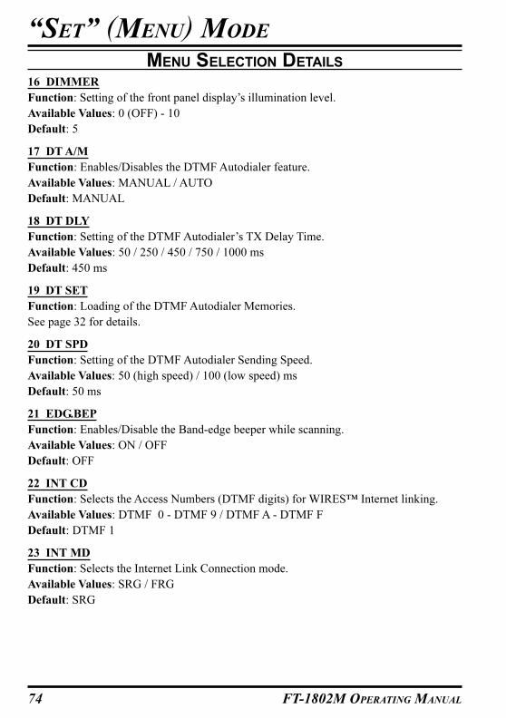
74 FT-1802M OPERATING MANUAL
“SET” (MENU) MODE
MENU SELECTION DETAILS
16 DIMMER
Function: Setting of the front panel display’s illumination level.
Available Values: 0 (OFF) - 10
Default: 5
17 DT A/M
Function: Enables/Disables the DTMF Autodialer feature.
Available Values: MANUAL / AUTO
Default: MANUAL
18 DT DLY
Function: Setting of the DTMF Autodialer’s TX Delay Time.
Available Values: 50 / 250 / 450 / 750 / 1000 ms
Default: 450 ms
19 DT SET
Function: Loading of the DTMF Autodialer Memories.
See page 32 for details.
20 DT SPD
Function: Setting of the DTMF Autodialer Sending Speed.
Available Values: 50 (high speed) / 100 (low speed) ms
Default: 50 ms
21 EDG.BEP
Function: Enables/Disable the Band-edge beeper while scanning.
Available Values: ON / OFF
Default: OFF
22 INT CD
Function: Selects the Access Numbers (DTMF digits) for WIRES™ Internet linking.
Available Values: DTMF 0 - DTMF 9 / DTMF A - DTMF F
Default: DTMF 1
23 INT MD
Function: Selects the Internet Link Connection mode.
Available Values: SRG / FRG
Default: SRG
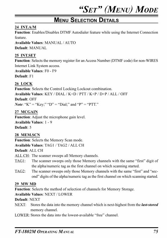
75FT-1802M OPERATING MANUAL
“SET” (MENU) MODE
MENU SELECTION DETAILS
24 INT.A/M
Function: Enables/Disables DTMF Autodialer feature while using the Internet Connection
feature.
Available Values: MANUAL / AUTO
Default: MANUAL
25 INT.SET
Function: Selects the memory register for an Access Number (DTMF code) for non-WIRES
Internet Link System access.
Available Values: F0 - F9
Default: F1
26 LOCK
Function: Selects the Control Locking Lockout combination.
Available Values: KEY / DIAL / K+D / PTT / K+P / D+P / ALL / OFF
Default: OFF
Note: “K” = “Key;” “D” = “Dial;” and “P” = “PTT.”
27 MCGAIN
Function: Adjust the microphone gain level.
Available Values: 1 - 9
Default: 5
28 MEM.SCN
Function: Selects the Memory Scan mode.
Available Values: TAG1 / TAG2 / ALL CH
Default: ALL CH
ALL CH: The scanner sweeps all Memory channels.
TAG1: The scanner sweeps only those Memory channels with the same “first” digit of
the alpha/numeric tag as the first channel on which scanning started.
TAG2: The scanner sweeps only those Memory channels with the same “first” and “sec-
ond” digits of the alpha/numeric tag as the first channel on which scanning started.
29 MW MD
Function: Selects the method of selection of channels for Memory Storage.
Available Values: NEXT / LOWER
Default: NEXT
NEXT: Stores the data into the memory channel which is next-highest from the last-stored
memory channel.
LOWER: Stores the data into the lowest-available “free” channel.
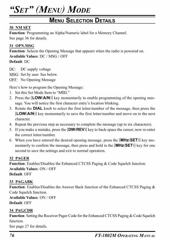
76 FT-1802M OPERATING MANUAL
“SET” (MENU) MODE
MENU SELECTION DETAILS
30 NM SET
Function: Programming an Alpha/Numeric label for a Memory Channel.
See page 36 for details.
31 OPN.MSG
Function: Selects the Opening Message that appears when the radio is powered on.
Available Values: DC / MSG / OFF
Default: DC
DC: DC supply voltage
MSG: Set by user. See below.
OFF: No Opening Message
Here’s how to program the Opening Message:
1. Set this Set Mode Item to “MSG.”
2. Press the [LOW(A/N)] key momentarily to enable programming of the opening mes-
sage. You will notice the first character entry’s location blinking.
3. Rotate the DIAL knob to select the first letter/number of the message, then press the
[LOW(A/N)] key momentarily to save the first letter/number and move on to the next
character.
4. Repeat the previous step as necessary to complete the message (up to six characters).
5. If you make a mistake, press the [DW(REV)] key to back-space the cursor; now re-enter
the correct letter/number.
6. When you have entered the desired opening message, press the [MHz(SET)] key mo-
mentarily to confirm the message, then press and hold in the [MHz(SET)] key for one
second to save the settings and exit to normal operation.
32 PAGER
Function: Enables/Disables the Enhanced CTCSS Paging & Code Squelch function.
Available Values: ON / OFF
Default: OFF
33 PAG.ABK
Function: Enables/Disables the Answer Back function of the Enhanced CTCSS Paging &
Code Squelch function.
Available Values: ON / OFF
Default: OFF
34 PAG.CDR
Function: Setting the Receiver Pager Code for the Enhanced CTCSS Paging & Code Squelch
function.
See page 27 for details.
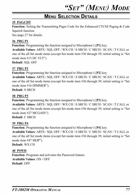
77FT-1802M OPERATING MANUAL
“SET” (MENU) MODE
MENU SELECTION DETAILS
35 PAG.CDT
Function: Setting the Transmitting Pager Code for the Enhanced CTCSS Paging & Code
Squelch function.
See page 27 for details.
36 PRG P1
Function: Programming the function assigned to Microphone’s [P1] key.
Available Values: ARTS / SQL OFF / WX CH / S SRCH / C SRCH / SCAN / T CALL or
one of the all Set mode items (except Set mode item #36 through 39; initial setting is “Set
mode item #13 DC VLT”).
Default: SQL OFF
37 PRG P2
Function: Programming the function assigned to Microphone’s [P2] key.
Available Values: ARTS / SQL OFF / WX CH / S SRCH / C SRCH / SCAN / T CALL or
one of the all Set mode items (except Set mode item #36 through 39; initial setting is “Set
mode item #16 DIMMER”).
Default: S SRCH
38 PRG P3
Function: Programming the function assigned to Microphone’s [P3] key.
Available Values: ARTS / SQL OFF / WX CH / S SRCH / C SRCH / SCAN / T CALL or
one of the all Set mode items (except Set mode item #36 through 39; initial setting is “Set
mode item #27 MCGAIN”).
Default: C SRCH
39 PRG P4
Function: Programming the function assigned to Microphone’s [P4] key.
Available Values: ARTS / SQL OFF / WX CH / S SRCH / C SRCH / SCAN / T CALL or
one of the all Set mode items (except Set mode item #36 through 39; initial setting is “Set
mode item #47 SKIP”).
Default: WX CH
40 PSWD
Function: Programs and activates the Password feature.
Available Values: ON / OFF
Default: OFF
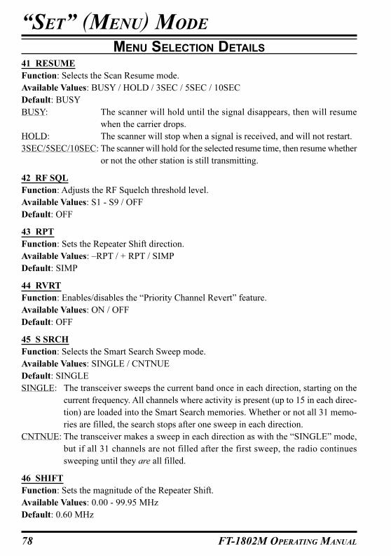
78 FT-1802M OPERATING MANUAL
41 RESUME
Function: Selects the Scan Resume mode.
Available Values: BUSY / HOLD / 3SEC / 5SEC / 10SEC
Default: BUSY
BUSY: The scanner will hold until the signal disappears, then will resume
when the carrier drops.
HOLD: The scanner will stop when a signal is received, and will not restart.
3SEC/5SEC/10SEC: The scanner will hold for the selected resume time, then resume whether
or not the other station is still transmitting.
42 RF SQL
Function: Adjusts the RF Squelch threshold level.
Available Values: S1 - S9 / OFF
Default: OFF
43 RPT
Function: Sets the Repeater Shift direction.
Available Values: –RPT / + RPT / SIMP
Default: SIMP
44 RVRT
Function: Enables/disables the “Priority Channel Revert” feature.
Available Values: ON / OFF
Default: OFF
45 S SRCH
Function: Selects the Smart Search Sweep mode.
Available Values: SINGLE / CNTNUE
Default: SINGLE
SINGLE: The transceiver sweeps the current band once in each direction, starting on the
current frequency. All channels where activity is present (up to 15 in each direc-
tion) are loaded into the Smart Search memories. Whether or not all 31 memo-
ries are filled, the search stops after one sweep in each direction.
CNTNUE: The transceiver makes a sweep in each direction as with the “SINGLE” mode,
but if all 31 channels are not filled after the first sweep, the radio continues
sweeping until they are all filled.
46 SHIFT
Function: Sets the magnitude of the Repeater Shift.
Available Values: 0.00 - 99.95 MHz
Default: 0.60 MHz
“SET” (MENU) MODE
MENU SELECTION DETAILS

79FT-1802M OPERATING MANUAL
47 SKIP
Function: Selects the Memory Scan mode.
Available Values: SKIP / ONLY / OFF
Default: OFF
SKIP: The scanner will “skip” the flagged channels during scanning.
ONLY: The scanner will only scan channels that are flagged (Preferential Scan List).
OFF: All memory channels will be scanned (the “flag” will be ignored).
48 SPLIT
Function: Enables/Disables split CTCSS/DCS coding.
Available Values: ON / OFF
Default: OFF
When this Set Mode Item is set to “ON,” you will see the following additional parameters
after the “RV TN” parameter while configuring Set Mode Item “49 SQL.TYP.”
D CODE: DCS Encode only.
T DCS: Encodes a CTCSS tone and Decodes a DCS code.
D TONE: Encodes a DCS code and Decodes a CTCSS tone.
49 SQL.TYP
Function: Selects the Tone Encoder and/or Decoder mode.
Available Values: TONE / TSQL / DCS / RV TN / OFF
Default: OFF
TONE: CTCSS Encoder
TSQL: CTCSS Encoder/Decoder
DCS: Digital Coded Encoder/Decoder
RV TN: Reverse CTCSS Decoder (Mutes receiver when matching tone is received)
Note: See also Set Mode Item “48 SPLIT” regarding additional selections available during
“Split Tone” operation.
50 STEP
Function: Sets the Synthesizer steps.
Available Values: 5 / 10 / 12.5 / 15 / 20 / 25 / 50 / 100 kHz
Default: USA: 5 kHz, EXP: 12.5 kHz
51 TEMP
Function: Indicates the current temperature inside the transceiver’s case.
Note: Press the [MHz(SET)] key repeatedly to toggle between Fahrenheit (°F) and Celsius
(°C) display of the temperature.
“SET” (MENU) MODE
MENU SELECTION DETAILS
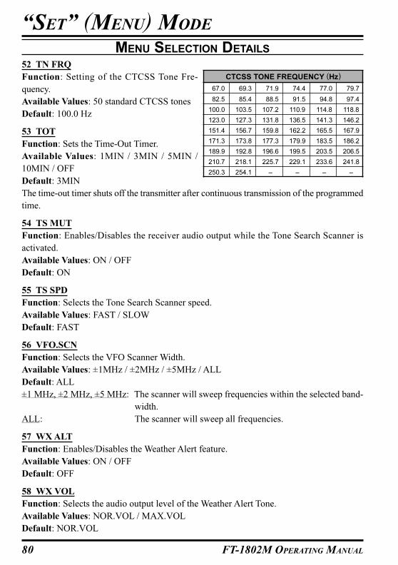
80 FT-1802M OPERATING MANUAL
52 TN FRQ
Function: Setting of the CTCSS Tone Fre-
quency.
Available Values: 50 standard CTCSS tones
Default: 100.0 Hz
53 TOT
Function: Sets the Time-Out Timer.
Available Values: 1MIN / 3MIN / 5MIN /
10MIN / OFF
Default: 3MIN
The time-out timer shuts off the transmitter after continuous transmission of the programmed
time.
54 TS MUT
Function: Enables/Disables the receiver audio output while the Tone Search Scanner is
activated.
Available Values: ON / OFF
Default: ON
55 TS SPD
Function: Selects the Tone Search Scanner speed.
Available Values: FAST / SLOW
Default: FAST
56 VFO.SCN
Function: Selects the VFO Scanner Width.
Available Values: ±1MHz / ±2MHz / ±5MHz / ALL
Default: ALL
±1 MHz, ±2 MHz, ±5 MHz: The scanner will sweep frequencies within the selected band-
width.
ALL: The scanner will sweep all frequencies.
57 WX ALT
Function: Enables/Disables the Weather Alert feature.
Available Values: ON / OFF
Default: OFF
58 WX VOL
Function: Selects the audio output level of the Weather Alert Tone.
Available Values: NOR.VOL / MAX.VOL
Default: NOR.VOL
“SET” (MENU) MODE
MENU SELECTION DETAILS
CTCSS TONE FREQUENCY (Hz)
67.0 69.3 71.9 74.4 77.0 79.7
82.5 85.4 88.5 91.5 94.8 97.4
100.0 103.5 107.2 110.9 114.8 118.8
123.0 127.3 131.8 136.5 141.3 146.2
151.4 156.7 159.8 162.2 165.5 167.9
171.3 173.8 177.3 179.9 183.5 186.2
189.9 192.8 196.6 199.5 203.5 206.5
210.7 218.1 225.7 229.1 233.6 241.8
250.3 254.1 – – – –
81FT-1802M OPERATING MANUAL
“SET” (MENU) MODE
MENU SELECTION DETAILS
59 W/N DV
Function: Reduction of the Microphone Gain/Deviation and receiver bandwidth.
Available Values: WIDE (±5 kHz Deviation, 15 kHz Bandwidth) / NARROW (±2.5 kHz
Deviation, 6 kHz Bandwidth)
Default: WIDE (±5 kHz Deviation, 15 kHz Bandwidth)

82 FT-1802M OPERATING MANUAL
NOTE
83FT-1802M OPERATING MANUAL
NOTE

84 FT-1802M OPERATING MANUAL
NOTE

1. Changes or modifications to this device not expressly approved by VERTEX
STANDARD could void the user’s authorization to operate this device.
2. This device complies with part 15 of the FCC Rules. Operation is subject to
the following two conditions; (1) this device may not cause harmful
interference, and (2) this device must accept any interference including
interference that may cause undesired operation.
3. The scanning receiver in this equipment is incapable of tuning, or readily
being altered, by the User to operate within the frequency bands allocated
to the Domestic public Cellular Telecommunications Service in Part 22.
WARNING: MODIFICATION OF THIS DEVICE TO RECEIVE CELLULAR
RADIOTELEPHONE SERVICE SIGNALS IS PROHIBITED UNDER FCC RULES
AND FEDERAL LAW.
DECLARATION BY MANUFACTURER
The Scanner receiver is not a digital scanner and is incapable of being converted
or modified to a digital scanner receiver by any user.
Part 15.21: Changes or modifications to this device not expressly approved
by Vertex Standard could void the user’s authorization to operate this device.

Copyright 2005
VERTEX STANDARD CO., LTD.
All rights reserved.
No portion of this manual
may be reproduced
without the permission of
VERTEX STANDARD CO., LTD. E H 0 2 3 N 1 0 0