fmi 751-071reva knuckle link arm replacement 751-071reva... · knuckle link arm replacement fmi...
TRANSCRIPT

Author: J. Juse L. Cervera
Field Modification Instruction Knuckle Link Arm Replacement
FMI 751‐071 10/27/15 Rev: A
Page 1 of 7
Field Modification Instructions for Project:
Knuckle Link Arm Inspection and Replacement
For Recall Number 15E-068
J. Juse/L. Cervera 10/27/2015
Author Date
D. DeLeo 10/27/2015
Director of Engineering Date

Author: J. Juse L. Cervera
Field Modification Instruction Knuckle Link Arm Replacement
FMI 751‐071 10/27/15 Rev: A
Page 2 of 7
Subject: Recall Number 15E-068 – Occurrence of Fatigue Cracks in certain S-Series Wheelchair Lifts
Reason: Under certain conditions present in some applications, the platforms included on the potentially affected S-Series model wheelchair lifts can exhibit cracking of the platform pivot plate while in the stowed position resulting from bent knuckle link arms and/or DU bearings that have fallen out of their holes in the Knuckle Link Arm. If left unchecked the platforms can develop cracks and can propagate to the point where the separation of the rear portion of the pivot plate occurs rendering the lift potentially in operable and possibly unsafe for the operator. These instructions and the material herein referenced are intended to mitigate the circumstances that can potentially precipitate the referenced cracking that is the subject of Ricon Recall number 15E-068.
Replacement Criteria: Knuckle Link Arms should only be replaced after the Knuckle Link Arms have been inspected for signs of wear or walking (bending due to DU bearing separation from Knuckle Link Arm hole). If signs of wear or walking are not visible then replacement is not necessary. If either of the following conditions are present then replacement will be required.
1. The Knuckle Link Arm is bent. Reference Figure 1A. 2. The DU bearings on the Knuckle Link arm have fallen out of the hole. Reference Figure 1B.
Figure 1A (Bent Knuckle Link Arm) Figure 1B (DU Bearing Separation)
Affected Units: Ricon DOT Public Use, ”S” 2000 and 5500 Series lifts manufactured after January 1, 2006 equipped with platforms measuring 32”x51” and 34”x54”. The affected population is comprised of six (6) primary model numbers:
S2005- XXXXXXXX / S2010-XXXXXXXX S5005-XXXXXXXX / S5010-XXXXXXXX S5505-XXXXXXXX / S5510-XXXXXXXX
Approximate completion time: 10 min

Author: J. Juse L. Cervera
Field Modification Instruction Knuckle Link Arm Replacement
FMI 751‐071 10/27/15 Rev: A
Page 3 of 7
Parts required:
LIFT SERIES KIT P/N DESCRIPTION QTY
S2005 RI55999 KIT, RETROFIT, LINK ARM SET, S2000 1
S2010 RI55999 KIT, RETROFIT, LINK ARM SET, S2000 1
S5005 RI58701 KIT, RETROFIT, LINK ARM SET, S5000 1
S5010 RI58701 KIT, RETROFIT, LINK ARM SET, S5000 1
S5505 RI55997 KIT, RETROFIT, LINK ARM SET, S5500 1
S5510 RI55997 KIT, RETROFIT, LINK ARM SET, S5500 1
Tools required:
Phillips Screwdriver Snap Ring Pliers, Right Angle Rubber Mallet
Figure 2. Left Hand Knuckle Link Arm Assembly (Shown)
Note: Follow all safety practices before attempting to work on wheelchair lift.
RSM0071600
DU BEARING
SNAP RINGSPACER
WASHER
SADDLE ASSEMBLY
SNAP RING
SNAP RING
UPPER LINK ARM
PIN
LOWER KNUCKLE LINK ARM�(NOTE: PART TO BE REPLACED
IF SIGNS OF WEAR ARE VISIBLE)
ACTUATOR SPRING
DU BEARING

Author: J. Juse L. Cervera
Field Modification Instruction Knuckle Link Arm Replacement
FMI 751‐071 10/27/15 Rev: A
Page 4 of 7
Safety Precautions
Under no circumstances is maintenance, repair, or adjustment of the product to be performed without the presence of an individual capable of giving aid.
This lift is driven with hydraulic pressure generated by a hydraulic pump system. The fluid is highly pressurized and possibly very hot. Use extreme caution when doing maintenance and repairs. DO NOT disconnect hoses or fittings when lift is in motion.
Give immediate attention to all injuries, and administer first-aid, or seek medical attention as necessary.
Protective eye shields and clothing should be worn during maintenance, repair, and adjustment of the lift.
Work in a properly ventilated area. Check for hidden obstructions before drilling and cutting. Avoid interference with wiring,
fuel tank, fuel lines, hydraulic lines, subfloor members, etc. Read and understand all instructions before attempting to operate the product. Read and understand all instructions before attempting to perform maintenance, repairs, or
adjustments to the product. Read and comply with warning labels attached to lift.
I. INSTALLATION OF KNUCKLE LINK ARM ASSEMBLY
Apply power to lift then deploy and lower platform to approximately 3-4 inches below vehicle floor level or any adequate position that allows for access to the Knuckle Link Arm assembly.
NOTE: Remove pinch-point shields before attempting to replace Knuckle Link Arm.
A. KNUCKLE LINK ARM REMOVAL
1. Refer to Figure 3. Locate Lower Knuckle Link Arm Snap Ring, bottom then remove Snap Ring. Retain Snap Ring for re-installation.
Figure 3. Lower Knuckle Link Arm Snap Ring, Bottom
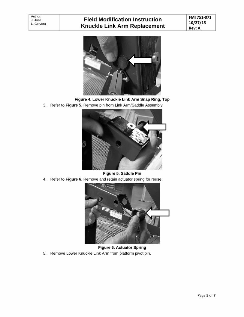
2. Refer to Figure 4. Locate Upper/Lower Link Arm joint then remove Snap Ring. Retain Snap Ring for re-installation.
Author: J. Juse L. Cervera
Field Modification Instruction Knuckle Link Arm Replacement
FMI 751‐071 10/27/15 Rev: A
Page 5 of 7
Figure 4. Lower Knuckle Link Arm Snap Ring, Top
3. Refer to Figure 5. Remove pin from Link Arm/Saddle Assembly.
Figure 5. Saddle Pin
4. Refer to Figure 6. Remove and retain actuator spring for reuse.
Figure 6. Actuator Spring
5. Remove Lower Knuckle Link Arm from platform pivot pin.

Author: J. Juse L. Cervera
Field Modification Instruction Knuckle Link Arm Replacement
FMI 751‐071 10/27/15 Rev: A
Page 6 of 7
Figure 7. Lower Knuckle Link Arm
B. KNUCKLE LINK ARM ASSEMBLY INSTALLATION
1. Refer to Figure 7. Slide lower portion of Knuckle Link Arm onto platform pivot.
Figure 8. Ensure Bushing Installs Correctly
2. Re-install one (1) 3/4" flat washer over platform pivot and re-install snap ring.
Figure 9. Install Washer and Snap Ring
3. Re-install actuator spring on upper portion of Link Arm.

Author: J. Juse L. Cervera
Field Modification Instruction Knuckle Link Arm Replacement
FMI 751‐071 10/27/15 Rev: A
Page 7 of 7
Figure 10. Install Actuator Spring
4. Re-install actuator spring on Upper Link Arm and install Saddle Assembly.
5. Re-install pin through upper portion of Knuckle Link assembly then re-install snap ring.
6. Repeat the steps 1-5 for the opposite Lower Knuckle Link Arm installation.
7. Re-install pinch point shields.
8. Perform stow and deploy cycle 2-3 times to ensure the wheelchair lift is working properly.