foam systems inductors & proportioners hardware... · fomtec foam systems inductors &...
TRANSCRIPT

Foam Systems Inductors & Proportioners
Document Fs i&p / Ver 1:2
Fomtec Foam Systems
Inductors & Proportioners • Accurate
Proportioning / Induction
• Corrosion Resistant • 1 ½” up to 10” • Wide Range • Between flange
construction • Suitable for ARC foam
concentrates • Easy to install
Dafo Fomtec AB, P.O. Box 683, SE-135 26 Tyresö, Sweden, Tel +46 8-506 405 00, Fax +46 8-506 405 29

Dafo Fomtec AB, P.O. Box 683, SE-135 26 Tyresö, Sweden, Tel +46 8-506 405 00, Fax +46 8-506 405 29
Inductors BFZ 1 ½ “ BFZ 2” BFZ 3” BFZ 4” BFZ 6” BFZ 8” BFZ 8” S
Balanced Pressure Proprotioners For Bladdertanks: GB 2“ BT GB 3” BT GB 4” BT GB 6” BG GB 8” BT GB 10” BT For Foam Pumps GB 3” FP GB 4” FP GB 6” FP GB 8” FP GB 10” FP
Balanced Pressure Proportioners Wide Range Type For Bladdertanks: WRP 6“ BT WRP 8“ BT WRP 10“ BT For Foam Pumps WRP 6“ FP WRP 8“ FP WRP 10“ FP

BFZ 1 ½ ” BETWEEN FLANGE INDUCTORS
Document BFZ 1 1-2,/ Ver 1:1
FEATURES • Fixed between-flange
installation • Flow rate up to 480 lpm • High back pressure • High suction height • Suites ARC foams
Description The Fomtec BFZ (Between Flange) inductor series represents an extension of the existing line of Z-inductors for fixed use. The BFZ 1 ½ ” can be used at flow rates up to 480 lpm.
Application The BFZ inductor can be installed in all fixed systems, especially in areas where sprinklers are used such as storage facilities and aircraft hangars.
Operation The BFZ is installed inside the pipe work between two DN flanges. The BFZ works using the injector principle, i.e. foam concentrate is sucked into the inductor without using a foam pump. Both low and high viscosity concentrates can be used in conjunction with the BFZ. Depending on the requested flow, pressure, foam concentrate type and proportioning ratio the inductor will be equipped with the exact orifice at the entry of the foam pipe. Induction performance and suction height can be adjusted up to a physical limit of approximately 8 meters.
Optional The Fomtec BFZ inductor can be customized to handle a variety of flow rates as well as high viscous alcohol resistant concentrates.
Picture shows the Fomtec BFZ 4”
Dafo Fomtec AB, P.O. Box 683, SE-135 26 Tyresö, Tel +46 8 506 405 66, Fax +46 8 506 405 29 Web: www.fomtec.com, E-Mail: [email protected]
Technical data Model BFZ 1 ½ ” Size DN 40 Foam inlet ½ ” Flow Rate (max) 480 lpm Flow rate (min) 80 lpm Inlet pressure (max) 16 bar Inlet pressure (min) 4 bar Pressure drop 35% K Factor 40-120 Proportioning rate 1, 3 or 6% Pipe length upstream 5 x Ø Pipe length downstream 6 x Ø Suction height (max) 3 m Flange type DN 40 / PN16 Between flange proportions 35 mm Weight 3 kg Length 225 mm Material Bronze
INDUCTORS WITHOUT BALANCING VALVE.
If Higher suction height is needed please specify when ordering The order to determine the K-factor: K-factor 1 = 1 lpm @ 1 bar ( Q=kx√P)
Dafo Fomtec AB, P.O. Box 683, SE-135 26 Tyresö, Tel +46 8 506 405 66, Fax +46 8 506 405 29 Web: www.fomtec.com, E-Mail: [email protected]
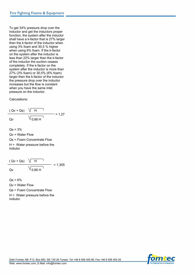
To get 34% pressure drop over the inductor and get the inductors proper function, the system after the inductor shall have a k-factor that is 27% larger then the k-factor of the inductor when using 3% foam and 30,5 % higher when using 6% foam. If the k-factor on the system after the inductor is less than 22% larger then the k-factor of the inductor the suction ceases completely. If the k-factor on the system after the inductor is more than 27% (3% foam) or 30,5% (6% foam) larger then the k-factor of the inductor the pressure drop over the inductor increases but the flow is constant when you have the same inlet pressure on the inductor. Calculations: ( Qv + Qs) H Qv 0,66 H Qs = 3% Qv = Water Flow Qs = Foam Concentrate Flow H = Water pressure before the indiutor ( Qv + Qs) H Qv 0,66 H Qs = 6% Qv = Water Flow Qs = Foam Concentrate Flow H = Water pressure before the indiutor
= 1,27
= 1,305
BFZ 2” BETWEEN FLANGE INDUCTORS
Document BFZ 3.doc,/ Ver 1:2
FEATURES • Fixed between-flange
installation • Flow rate up to 720 lpm • High back pressure • High suction height • Suites ARC foams
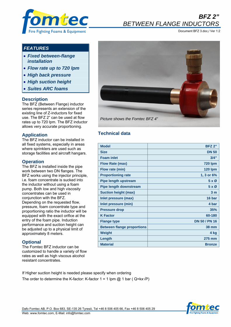
Description The BFZ (Between Flange) inductor series represents an extension of the existing line of Z-inductors for fixed use. The BFZ 2” can be used at flow rates up to 720 lpm. The BFZ inductor allows very accurate proportioning.
Application The BFZ inductor can be installed in all fixed systems, especially in areas where sprinklers are used such as storage facilities and aircraft hangars.
Operation The BFZ is installed inside the pipe work between two DN flanges. The BFZ works using the injector principle, i.e. foam concentrate is sucked into the inductor without using a foam pump. Both low and high viscosity concentrates can be used in conjunction with the BFZ. Depending on the requested flow, pressure, foam concentrate type and proportioning ratio the inductor will be equipped with the exact orifice at the entry of the foam pipe. Induction performance and suction height can be adjusted up to a physical limit of approximately 8 meters.
Optional The Fomtec BFZ inductor can be customized to handle a variety of flow rates as well as high viscous alcohol resistant concentrates.
Picture shows the Fomtec BFZ 4”
Technical data
Model BFZ 2” Size DN 50 Foam inlet 3/4” Flow Rate (max) 720 lpm Flow rate (min) 120 lpm Proportioning rate 1, 3 or 6% Pipe length upstream 5 x Ø Pipe length downstream 5 x Ø Suction height (max) 3 m Inlet pressure (max) 16 bar Inlet pressure (min) 4 bar Pressure drop 35% K Factor 60-180 Flange type DN 50 / PN 16 Between flange proportions 38 mm Weight 4 kg Length 275 mm Material Bronze
If Higher suction height is needed please specify when ordering
The order to determine the K-factor: K-factor 1 = 1 lpm @ 1 bar ( Q=kx√P)
Dafo Fomtec AB, P.O. Box 683, SE-135 26 Tyresö, Tel +46 8 506 405 66, Fax +46 8 506 405 29 Web: www.fomtec.com, E-Mail: [email protected]

Dafo Fomtec AB, P.O. Box 683, SE-135 26 Tyresö, Tel +46 8 506 405 66, Fax +46 8 506 405 29 Web: www.fomtec.com, E-Mail: [email protected]
INDUCTORS WITHOUT BALANCING VALVE. To get 34% pressure drop over the inductor and get the inductors proper function, the system after the inductor shall have a k-factor that is 27% larger then the k-factor of the inductor when using 3% foam and 30,5 % higher when using 6% foam. If the k-factor on the system after the inductor is less than 22% larger then the k-factor of the inductor the suction ceases completely. If the k-factor on the system after the inductor is more than 27% (3% foam) or 30,5% (6% foam) larger then the k-factor of the inductor the pressure drop over the inductor increases but the flow is constant when you have the same inlet pressure on the inductor. Calculations: ( Qv + Qs) H = 1,27 Qv 0,66 H Qs = 3% Qv = Water Flow Qs = Foam Concentrate Flow H = Water pressure before the indiutor ( Qv + Qs) H = 1,305 Qv 0,66 H Qs = 6% Qv = Water Flow Qs = Foam Concentrate Flow H = Water pressure before the inductor

BFZ 3” BETWEEN FLANGE INDUCTORS
Document BFZ 3.doc,/ Ver 1:2
FEATURES • Fixed between-flange
installation • Flow rate up to 2000 lpm • High back pressure • High suction height • Suites ARC foams
Description The BFZ (Between Flange) inductor series represents an extension of the existing line of Z-inductors for fixed use. The BFZ 3” can be used at flow rates up to 2000 lpm. The BFZ inductor allows very accurate proportioning.
Application The BFZ inductor can be installed in all fixed systems, especially in areas where sprinklers are used such as storage facilities and aircraft hangars.
Operation The BFZ is installed inside the pipe work between two DN flanges. The BFZ works using the injector principle, i.e. foam concentrate is sucked into the inductor without using a foam pump. Both low and high viscosity concentrates can be used in conjunction with the BFZ. Depending on the requested flow, pressure, foam concentrate type and proportioning ratio the inductor will be equipped with the exact orifice at the entry of the foam pipe. Induction performance and suction height can be adjusted up to a physical limit of approximately 8 meters.
Optional The Fomtec BFZ inductor can be customized to handle a variety of flow rates as well as high viscous alcohol resistant concentrates.
Picture shows the Fomtec BFZ 4”
Technical data
Model BFZ 3” Size DN 80 Foam inlet 1” Flow Rate (max) 2000 lpm Flow rate (min) 360 lpm Proportioning rate 1, 3 or 6% Pipe length upstream 5 x Ø Pipe length downstream 5 x Ø Suction height (max) 3 m Inlet pressure (max) 16 bar Inlet pressure (min) 4 bar Pressure drop 35% K Factor 180-500 Flange type DN 80 / PN 16 Between flange proportions 52 mm Weight 6 kg Length 405 mm Material Bronze
If Higher suction height is needed please specify when ordering The order to determine the K-factor: K-factor 1 = 1 lpm @ 1 bar ( Q=kx√P)
Dafo Fomtec AB, P.O. Box 683, SE-135 26 Tyresö, Tel +46 8 506 405 66, Fax +46 8 506 405 29 Web: www.fomtec.com, E-Mail: [email protected]

Dafo Fomtec AB, P.O. Box 683, SE-135 26 Tyresö, Tel +46 8 506 405 66, Fax +46 8 506 405 29 Web: www.fomtec.com, E-Mail: [email protected]
INDUCTORS WITHOUT BALANCING VALVE. To get 34% pressure drop over the inductor and get the inductors proper function, the system after the inductor shall have a k-factor that is 27% larger then the k-factor of the inductor when using 3% foam and 30,5 % higher when using 6% foam. If the k-factor on the system after the inductor is less than 22% larger then the k-factor of the inductor the suction ceases completely. If the k-factor on the system after the inductor is more than 27% (3% foam) or 30,5% (6% foam) larger then the k-factor of the inductor the pressure drop over the inductor increases but the flow is constant when you have the same inlet pressure on the inductor. Calculations: ( Qv + Qs) H = 1,27 Qv 0,66 H Qs = 3% Qv = Water Flow Qs = Foam Concentrate Flow H = Water pressure before the indiutor ( Qv + Qs) H = 1,305 Qv 0,66 H Qs = 6% Qv = Water Flow Qs = Foam Concentrate Flow H = Water pressure before the indiutor

BFZ 4” BETWEEN FLANGE INDUCTORS
Document BFZ 4.doc,/ Ver 1:2
FEATURES • Fixed between-flange
installation • Flow rate up to 3300 lpm • High back pressure • High suction height • Suites ARC foams
Description The BFZ (Between Flange) inductor series represents an extension of the existing line of Z-inductors for fixed use. The BFZ 4” can be used at flow rates up to 3300 lpm. The BFZ inductor allows very accurate proportioning.
Application The BFZ inductor can be installed in all fixed systems, especially in areas where sprinklers are used such as storage facilities and aircraft hangars.
Operation The BFZ is installed inside the pipe work between two DN flanges. The BFZ works using the injector principle, i.e. foam concentrate is sucked into the inductor without using a foam pump. Both low and high viscosity concentrates can be used in conjunction with the BFZ. Depending on the requested flow, pressure, foam concentrate type and proportioning ratio the inductor will be equipped with the exact orifice at the entry of the foam pipe. Induction performance and suction height can be adjusted up to a physical limit of approximately 8 meters.
Optional The BFZ inductor can be customized to handle a variety of flow rates as well as high viscous alcohol resistant concentrates. If Higher suction height is needed please specify when ordering The order to determine the K-factor: K-factor 1 = 1 lpm @ 1 bar ( Q=kx√P)
Construction The Fomtec BFZ 4” inductor consists of a nozzle and a diffusor. The BFZ inductor also allows very accurate proportioning by means of a balance valve which compensates for unforeseen changes in back pressure. Not designed variations of pressure loss due to extra piping or failure of individual sprinkler nozzles will no longer represent a problem. A non-return valve at the entry of the foam pipe prevents water from flowing into the foam container after system is shut down.
Technical data Model BFZ 4“ Size DN 100 Foam inlet 1 ½” Flow Rate (max) 3300 lpm Flow rate (min) 550 lpm Proportioning rate 1, 3 or 6% Pipe length upstream 5 x Ø Pipe length downstream 5 x Ø Suction height (max) 3 m Inlet pressure (max) 16 bar Inlet pressure (min) 4 bar Pressure drop 35% K Factor 275-1000 Flange type DN 100 / PN 16 Between flange proportions 58 mm Weight 7 kg Length 415 mm Material Bronze
Dafo Fomtec AB, P.O. Box 683, SE-135 26 Tyresö, Tel +46 8 506 405 66, Fax +46 8 506 405 29 Web: www.fomtec.com, E-Mail: [email protected]

Dafo Fomtec AB, P.O. Box 683, SE-135 26 Tyresö, Tel +46 8 506 405 66, Fax +46 8 506 405 29 Web: www.fomtec.com, E-Mail: [email protected]
INDUCTORS WITHOUT BALANCING VALVE. To get 34% pressure drop over the inductor and get the inductors proper function, the system after the inductor shall have a k-factor that is 27% larger then the k-factor of the inductor when using 3% foam and 30,5 % higher when using 6% foam. If the k-factor on the system after the inductor is less than 22% larger then the k-factor of the inductor the suction ceases completely. If the k-factor on the system after the inductor is more than 27% (3% foam) or 30,5% (6% foam) larger then the k-factor of the inductor the pressure drop over the inductor increases but the flow is constant when you have the same inlet pressure on the inductor. Calculations: ( Qv + Qs) H = 1,27 Qv 0,66 H Qs = 3% Qv = Water Flow Qs = Foam Concentrate Flow H = Water pressure before the indiutor ( Qv + Qs) H = 1,305 Qv 0,66 H Qs = 6% Qv = Water Flow Qs = Foam Concentrate Flow H = Water pressure before the indiutor

BFZ 6” BETWEEN FLANGE INDUCTORS
Document BFZ 6.doc,/ Ver 1:2
FEATURES • Fixed between-flange
installation • Flow rate up to 6600 lpm • High back pressure • High suction height • Suites ARC foams
Description The Fomtec BFZ (Between Flange) inductor series represents an extension of the existing line of Z-inductors for fixed use. The BFZ 6” can be used at flow rates up to 6600 lpm.
Application The BFZ inductor can be installed in all fixed systems, especially in areas where sprinklers are used such as storage facilities and aircraft hangars.
Operation The BFZ is installed inside the pipe work between two DN flanges. The BFZ works using the injector principle, i.e. foam concentrate is sucked into the inductor without using a foam pump. Both low and high viscosity concentrates can be used in conjunction with the BFZ. Depending on the requested flow, pressure, foam concentrate type and proportioning ratio the inductor will be equipped with the exact orifice at the entry of the foam pipe. Induction performance and suction height can be adjusted up to a physical limit of approximately 8 meters.
Optional The Fomtec BFZ inductor can be customized to handle a variety of flow rates as well as high viscous alcohol resistant concentrates.
Technical data Model BFZ 6“ Size DN 150 Foam inlet 2” Flow Rate (max) 6600 lpm Flow rate (min) 1100 lpm Proportioning rate 1, 3 or 6 % Pipe length upstream 5 x Ø Pipe length downstream 5 x Ø Suction height (max) 3 m Inlet pressure (max) 16 bar Inlet pressure (min) 4 bar Pressure drop 35% K Factor 550-2000 Flange type DN 150 / PN 16 Between flange proportions 70 mm Weight 21 kg Length 450 mm Material Bronze
If Higher suction height is needed please specify when ordering The order to determine the K-factor: K-factor 1 = 1 lpm @ 1 bar ( Q=kx√P)
Dafo Fomtec AB, P.O. Box 683, SE-135 26 Tyresö, Tel +46 8 506 405 66, Fax +46 8 506 405 29 Web: www.fomtec.com, E-Mail: [email protected]

Dafo Fomtec AB, P.O. Box 683, SE-135 26 Tyresö, Tel +46 8 506 405 66, Fax +46 8 506 405 29 Web: www.fomtec.com, E-Mail: [email protected]
INDUCTORS WITHOUT BALANCING VALVE. To get 34% pressure drop over the inductor and get the inductors proper function, the system after the inductor shall have a k-factor that is 27% larger then the k-factor of the inductor when using 3% foam and 30,5 % higher when using 6% foam. If the k-factor on the system after the inductor is less than 22% larger then the k-factor of the inductor the suction ceases completely. If the k-factor on the system after the inductor is more than 27% (3% foam) or 30,5% (6% foam) larger then the k-factor of the inductor the pressure drop over the inductor increases but the flow is constant when you have the same inlet pressure on the inductor. Calculations: ( Qv + Qs) H = 1,27 Qv 0,66 H Qs = 3% Qv = Water Flow Qs = Foam Concentrate Flow H = Water pressure before the indiutor ( Qv + Qs) H = 1,305 Qv 0,66 H Qs = 6% Qv = Water Flow Qs = Foam Concentrate Flow H = Water pressure before the indiutor

BFZ 8” BETWEEN FLANGE INDUCTORS
Document BFZ 8.doc,/ Ver 1:2
FEATURES • Fixed between-flange
installation • Flow rate up to 9900 lpm • High back pressure • High suction height • Suites ARC foams
Description The Fomtec BFZ (Between Flange) inductor series represents an extension of the existing line of Z-inductors for fixed use. The BFZ 8” can be used at flow rates up to 9900 lpm.
Application The BFZ inductor can be installed in all fixed systems, especially in areas where sprinklers are used such as storage facilities and aircraft hangars.
Operation The BFZ is installed inside the pipe work between two DN flanges. The BFZ works using the injector principle, i.e. foam concentrate is sucked into the inductor without using a foam pump. Both low and high viscosity concentrates can be used in conjunction with the BFZ. Depending on the requested flow, pressure, foam concentrate type and proportioning ratio the inductor will be equipped with the exact orifice at the entry of the foam pipe. Induction performance and suction height can be adjusted up to a physical limit of approximately 8 meters.
Optional The Fomtec BFZ inductor can be customized to handle a variety of flow rates as well as high viscous alcohol resistant concentrates.
Picture Show BFZ 6”
Technical data Model BFZ 8“ Size DN 200 Foam inlet 2 ½ “ Flow Rate (max) 9900 lpm Flow rate (min) 1650 lpm Proportioning rate 1, 3 or 6% Pipe length upstream 5 x Ø Pipe length downstream 5 x Ø Suction height (max) 3 m Inlet pressure (max) 16 bar Inlet pressure (min) 4 bar Pressure drop 35% K Factor 825-3000 Flange type DN 200 / PN 16 Between flange proportions 85 mm Weight 40 kg Length 485 mm Material Bronze
If Higher suction height is needed please specify when ordering
The order to determine the K-factor: K-factor 1 = 1 lpm @ 1 bar ( Q=kx√P)
Dafo Fomtec AB, P.O. Box 683, SE-135 26 Tyresö, Tel +46 8 506 405 66, Fax +46 8 506 405 29 Web: www.fomtec.com, E-Mail: [email protected]

Dafo Fomtec AB, P.O. Box 683, SE-135 26 Tyresö, Tel +46 8 506 405 66, Fax +46 8 506 405 29 Web: www.fomtec.com, E-Mail: [email protected]
INDUCTORS WITHOUT BALANCING VALVE. To get 34% pressure drop over the inductor and get the inductors proper function, the system after the inductor shall have a k-factor that is 27% larger then the k-factor of the inductor when using 3% foam and 30,5 % higher when using 6% foam. If the k-factor on the system after the inductor is less than 22% larger then the k-factor of the inductor the suction ceases completely. If the k-factor on the system after the inductor is more than 27% (3% foam) or 30,5% (6% foam) larger then the k-factor of the inductor the pressure drop over the inductor increases but the flow is constant when you have the same inlet pressure on the inductor. Calculations: ( Qv + Qs) H = 1,27 Qv 0,66 H Qs = 3% Qv = Water Flow Qs = Foam Concentrate Flow H = Water pressure before the indiutor ( Qv + Qs) H = 1,305 Qv 0,66 H Qs = 6% Qv = Water Flow Qs = Foam Concentrate Flow H = Water pressure before the indiutor
BFZ 8” S BETWEEN FLANGE INDUCTORS
Document BFZ 8 S.doc,/ Ver 1:1
FEATURES • Fixed between-flange
installation • Flow rate up to 16500 lpm • High back pressure • High suction height • Suites ARC foams
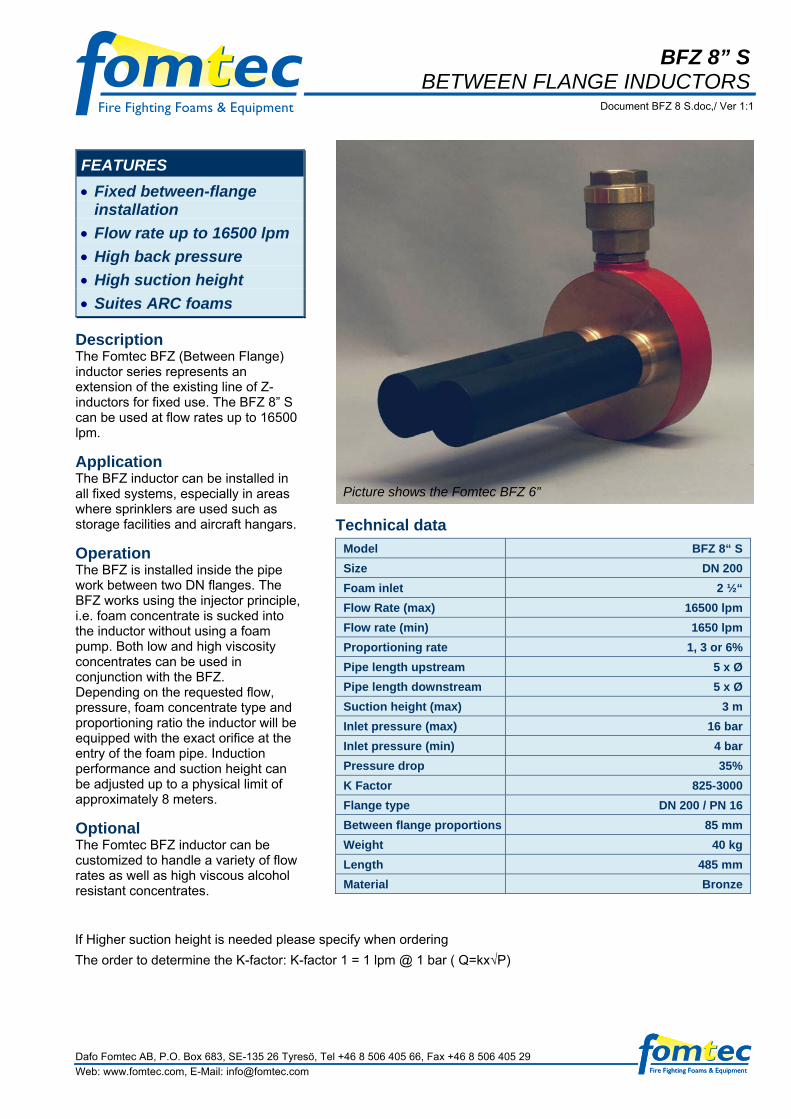
Description The Fomtec BFZ (Between Flange) inductor series represents an extension of the existing line of Z-inductors for fixed use. The BFZ 8” S can be used at flow rates up to 16500 lpm.
Application The BFZ inductor can be installed in all fixed systems, especially in areas where sprinklers are used such as storage facilities and aircraft hangars.
Operation The BFZ is installed inside the pipe work between two DN flanges. The BFZ works using the injector principle, i.e. foam concentrate is sucked into the inductor without using a foam pump. Both low and high viscosity concentrates can be used in conjunction with the BFZ. Depending on the requested flow, pressure, foam concentrate type and proportioning ratio the inductor will be equipped with the exact orifice at the entry of the foam pipe. Induction performance and suction height can be adjusted up to a physical limit of approximately 8 meters.
Optional The Fomtec BFZ inductor can be customized to handle a variety of flow rates as well as high viscous alcohol resistant concentrates.
Picture shows the Fomtec BFZ 6”
Technical data Model BFZ 8“ S Size DN 200 Foam inlet 2 ½“ Flow Rate (max) 16500 lpm Flow rate (min) 1650 lpm Proportioning rate 1, 3 or 6% Pipe length upstream 5 x Ø Pipe length downstream 5 x Ø Suction height (max) 3 m Inlet pressure (max) 16 bar Inlet pressure (min) 4 bar Pressure drop 35% K Factor 825-3000 Flange type DN 200 / PN 16 Between flange proportions 85 mm Weight 40 kg Length 485 mm Material Bronze
If Higher suction height is needed please specify when ordering
The order to determine the K-factor: K-factor 1 = 1 lpm @ 1 bar ( Q=kx√P)
Dafo Fomtec AB, P.O. Box 683, SE-135 26 Tyresö, Tel +46 8 506 405 66, Fax +46 8 506 405 29 Web: www.fomtec.com, E-Mail: [email protected]

Dafo Fomtec AB, P.O. Box 683, SE-135 26 Tyresö, Tel +46 8 506 405 66, Fax +46 8 506 405 29 Web: www.fomtec.com, E-Mail: [email protected]
INDUCTORS WITHOUT BALANCING VALVE. To get 34% pressure drop over the inductor and get the inductors proper function, the system after the inductor shall have a k-factor that is 27% larger then the k-factor of the inductor when using 3% foam and 30,5 % higher when using 6% foam. If the k-factor on the system after the inductor is less than 22% larger then the k-factor of the inductor the suction ceases completely. If the k-factor on the system after the inductor is more than 27% (3% foam) or 30,5% (6% foam) larger then the k-factor of the inductor the pressure drop over the inductor increases but the flow is constant when you have the same inlet pressure on the inductor. Calculations: ( Qv + Qs) H = 1,27 Qv 0,66 H Qs = 3% Qv = Water Flow Qs = Foam Concentrate Flow H = Water pressure before the indiutor ( Qv + Qs) H = 1,305 Qv 0,66 H Qs = 6% Qv = Water Flow Qs = Foam Concentrate Flow H = Water pressure before the indiutor

GB 2” BT PROPORTIONER
Document GB 2 BT / Ver 1:2
FEATURES • Available from 2” to 10” • 1 to 6% induction. • Usable with river and sea
water • Low maintenance • Low pressure drop
Description The GB proportioner is a high performance foam proportioner designed for use with foam pumps or bladder tanks.The proportioner comes in sizes from 2 inch up to 10 inch, and is for between flange mounting. The GB 2” BT is designed to work with Bladdertanks The foam proportioning can be either pre-set to any value between 1 and 6% or we deliver the GB with an adjustable valve for selection of mixing ratio between 1 and 6%. K-factor 1 = 1 lpm @ 1 bar (Q=Kx√P) Proportioning ratio can be ordered for 0 – 6 % When ordering for higher then 100% flow or when ordering 6% mention this on order (Larger check valve is needed)
Technical data Model GB 2” BT
Size DN 50
Foam inlet DN 20
Flow rate (max) 1100 lpm
Flow rate (min) AFFF/ARC 110/220 lpm
Flow range AFFF/ARC 1:10 / 1:5
Proportioning rate 3%
Inlet pressure (max) 16 bar
Inlet pressure (min) 3 bar
K-factor 350
Flange type DIN PN16
Between flange proportions
33 mm
Height 125 mm
Weight 2,5 kg
Material Bronze, Compatible with all foam concentrates
Dafo Fomtec AB, P.O. Box 683, SE-135 26 Tyresö, Tel +46 8-506 405 00, Fax +46 8-506 405 29

Dafo Fomtec AB, P.O. Box 683, SE-135 26 Tyresö, Tel +46 8-506 405 00, Fax +46 8-506 405 29
6,9
4,4
2,4
1,1
50% 75% 100% 125%
Pressure drop (bar)
Flow
Percentage of max flow
125
110100
80
8 10 12 16Bar
Min flow10

Dafo Fomtec AB, P.O. Box 683, SE-135 26 Tyresö, Tel +46 8-506 405 00, Fax +46 8-506 405 29
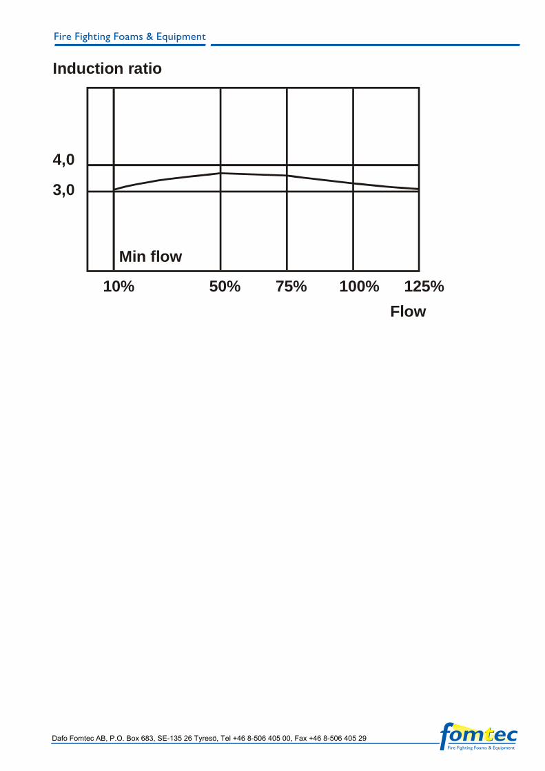
Induction ratio
4,0
3,0
Min flow
10% 50% 75% 100% 125%Flow

GB 3” BT PROPORTIONER
Document GB 3 BT / Ver 1:2
FEATURES • Available from 2” to 10” • 1 to 6% induction. • Usable with river and sea
water • Low maintenance • Low pressure drop
Description The GB proportioner is a high performance foam proportioner designed for use with foam pumps or bladder tanks.The proportioner comes in sizes from 2 inch up to 10 inch, and is for between flange mounting. The GB 3” BT is designed to work with Bladdertanks The foam proportioning can be either pre-set to any value between 1 and 6% or we deliver the GB with an adjustable valve for selection of mixing ratio between 1 and 6%. K-factor 1 = 1 lpm @ 1 bar (Q=Kx√P) Proportioning ratio can be ordered for 0 – 6 % When ordering for higher then 100% flow or when ordering 6% mention this on order (Larger check valve is needed)
Technical data Model GB 3” BT
Size DN 80
Foam inlet DN 25
Flow rate (max) 3000 lpm
Flow rate (min) AFFF/ARC 300/600 lpm
Flow range AFFF/ARC 1:10 / 1:5
Proportioning rate Specify in order
Inlet pressure (max) 16 bar
Inlet pressure (min) 3 bar
K-factor 950
Flange type DIN PN16
Between flange proportions
50 mm
Height 145 mm
Weight 4,0 kg
Material Bronze, Compatible with all foam Concentrates
Dafo Fomtec AB, P.O. Box 683, SE-135 26 Tyresö, Tel +46 8-506 405 00, Fax +46 8-506 405 29

Dafo Fomtec AB, P.O. Box 683, SE-135 26 Tyresö, Tel +46 8-506 405 00, Fax +46 8-506 405 29
6,9
4,4
2,4
1,1
50% 75% 100% 125%
Pressure drop (bar)
Flow
Percentage of max flow
125
110100
80
8 10 12 16Bar
Min flow10

Dafo Fomtec AB, P.O. Box 683, SE-135 26 Tyresö, Tel +46 8-506 405 00, Fax +46 8-506 405 29
Induction ratio
4,0
3,0
Min flow
10% 50% 75% 100% 125%Flow

GB 4” BT PROPORTIONER
Document GB 4 BT / Ver 1:2
FEATURES • Available from 2” to 10” • 1 to 6% induction • Usable with river and sea
water • Low maintenance • Low pressure drop
Description The GB proportioner is a high performance foam proportioner designed for use with foam pumps or bladder tanks.The proportioner comes in sizes from 2 inch up to 10 inch, and is for between flange mounting. The GB 4” BT is designed to work with Bladdertanks The foam proportioning can be either pre-set to any value between 1 and 6% or we deliver the GB with an adjustable valve for selection of mixing ratio between 1 and 6%. K-factor 1 = 1 lpm @ 1 bar (Q=Kx√P) Proportioning ratio can be ordered for 0 – 6 % When ordering for higher then 100% flow or when ordering 6% mention this on order (Larger check valve is needed)
Technical data Model GB 4” BT
Size DN 100
Foam inlet DN 40
Flow rate (max) 6000 lpm
Flow rate (min) AFFF/ARC 600/1200 lpm
Flow range AFFF/ARC 1:10 / 1:5
Proportioning rate 3%
Inlet pressure (max) 16 bar
Inlet pressure (min) 3 bar
K-factor 1930
Flange type DIN PN16
Between flange proportions 58 mm
Height 160mm
Weight 4,5 kg
Material Bronze, Compatible with all foam concentrates
Dafo Fomtec AB, P.O. Box 683, SE-135 26 Tyresö, Tel +46 8-506 405 00, Fax +46 8-506 405 29 Web: www.fomtec.com, E-Mail: [email protected]

Dafo Fomtec AB, P.O. Box 683, SE-135 26 Tyresö, Tel +46 8-506 405 00, Fax +46 8-506 405 29 Web: www.fomtec.com, E-Mail: [email protected]
6,9
4,4
2,4
1,1
50% 75% 100% 125%
Pressure drop (bar)
Flow
Percentage of max flow
125
110100
80
8 10 12 16Bar
Min flow10

Dafo Fomtec AB, P.O. Box 683, SE-135 26 Tyresö, Tel +46 8-506 405 00, Fax +46 8-506 405 29 Web: www.fomtec.com, E-Mail: [email protected]
Induction ratio
4,0
3,0
Min flow
10% 50% 75% 100% 125%Flow

GB 6”BT PROPORTIONER
Document GB 6 BT / Ver 1:2
FEATURES • Available from 2” to 10” • 1 to 6% induction. • Usable with river and sea
water • Low maintenance • Low pressure drop
Description The GB proportioner is a high performance foam proportioner designed for use with foam pumps or bladder tanks.The proportioner comes in sizes from 2 inch up to 10 inch, and is for between flange mounting. The GB 6” BT is designed to work with Bladdertanks The foam proportioning can be either pre-set to any value between 1 and 6% or we deliver the GB with an adjustable valve for selection of mixing ratio between 1 and 6%. K-factor 1 = 1 lpm @ 1 bar (Q=Kx√P) Proportioning ratio can be ordered for 0 – 6 % When ordering for higher then 100% flow or when ordering 6% mention this on order (Larger check valve is needed)
Technical data Model GB 6” BT
Size DN 150
Foam inlet DN 50
Flow rate (max) 12900 lpm
Flow rate (min) AFFF/ARC 1300/2600 lpm
Flow range AFFF/ARC 1:10 / 1:5
Proportioning rate 3%Inlet pressure (max) 16 barInlet pressure (min) 3 barK-factor 4090
Flange type DIN PN16
Between flange proportions
74 mm
Height 200 mm
Weight 11,0 kg
Material Bronze, Compatible with all foam concentrates
Dafo Fomtec AB, P.O. Box 683, SE-135 26 Tyresö, Tel +46 8-506 405 00, Fax +46 8-506 405 29

Dafo Fomtec AB, P.O. Box 683, SE-135 26 Tyresö, Tel +46 8-506 405 00, Fax +46 8-506 405 29
6,9
4,4
2,4
1,1
50% 75% 100% 125%
Pressure drop (bar)
Flow
Percentage of max flow
125
110100
80
8 10 12 16Bar
Min flow10
Dafo Fomtec AB, P.O. Box 683, SE-135 26 Tyresö, Tel +46 8-506 405 00, Fax +46 8-506 405 29
Induction ratio
4,0
3,0
Min flow
10% 50% 75% 100% 125%Flow

GB 8” BT PROPORTIONER
Document GB 8 BT / Ver 1:2
FEATURES • Available from 2” to 10” • 1 to 6% induction. • Usable with river and sea
water • Low maintenance • Low pressure drop
Description The GB proportioner is a high performance foam proportioner designed for use with foam pumps or bladder tanks.The proportioner comes in sizes from 2 inch up to 10 inch, and is for between flange mounting. The GB 8” BT is designed to work with Bladdertanks The foam proportioning can be either pre-set to any value between 1 and 6% or we deliver the GB with an adjustable valve for selection of mixing ratio between 1 and 6%. K-factor 1 = 1 lpm @ 1 bar (Q=Kx√P) Proportioning ratio can be ordered for 0 – 6 % When ordering for higher then 100% flow or when ordering 6% mention this on order (Larger check valve is needed)
Technical data Model GB 8” BT
Size DN 200
Foam inlet DN 65
Flow rate (max) 18800 lpm
Flow rate (min) AFFF/ARC 1800/3600 lpm
Flow range AFFF/ARC 1:10 / 1:5
Proportioning rate 3%
Inlet pressure (max) 16 bar
Inlet pressure (min) 3 bar
K-factor 5940
Flange type DIN PN16
Between flange proportions 85 mm
Height 235 mm
Weight 23,0 kg
Material Bronze, Compatible with all foam concentrates
Dafo Fomtec AB, P.O. Box 683, SE-135 26 Tyresö, Tel +46 8-506 405 00, Fax +46 8-506 405 29

Dafo Fomtec AB, P.O. Box 683, SE-135 26 Tyresö, Tel +46 8-506 405 00, Fax +46 8-506 405 29
6,9
4,4
2,4
1,1
50% 75% 100% 125%
Pressure drop (bar)
Flow
Percentage of max flow
125
110100
80
8 10 12 16Bar
Min flow10

Dafo Fomtec AB, P.O. Box 683, SE-135 26 Tyresö, Tel +46 8-506 405 00, Fax +46 8-506 405 29
Induction ratio
4,0
3,0
Min flow
10% 50% 75% 100% 125%Flow

GB 10” BT PROPORTIONER
Document GB 10 BT / Ver 1:2
FEATURES • Available from 2” to 10” • 1 to 6% induction. • Usable with river and sea
water • Low maintenance • Low pressure drop
Description The GB proportioner is a high performance foam proportioner designed for use with foam pumps or bladder tanks.The proportioner comes in sizes from 2 inch up to 10 inch, and is for between flange mounting. The GB 10” BT is designed to work with Bladdertanks The foam proportioning can be either pre-set to any value between 1 and 6% or we deliver the GB with an adjustable valve for selection of mixing ratio between 1 and 6%. K-factor 1 = 1 lpm @ 1 bar (Q=Kx√P) Proportioning ratio can be ordered for 0 – 6 % When ordering for higher then 100% flow or when ordering 6% mention this on order (Larger check valve is needed)
Technical data Model GB10” BT
Size DN 250
Foam inlet DN 80
Flow rate (max) 24000 lpm
Flow rate (min) AFFF/ARC 2400/4800 lpm
Flow range AFFF/ARC 1:10 / 1:5
Proportioning rate 3%
Inlet pressure (max) 16bar
Inlet pressure (min) 3 bar
K-factor 7580
Flange type DIN PN16
Between flange proportions 100 mm
Height 310 mm
Weight 32,0 kg
Material Bronze, Compatible with all foam concentrates
Dafo Fomtec AB, P.O. Box 683, SE-135 26 Tyresö, Tel +46 8-506 405 00, Fax +46 8-506 405 29

Dafo Fomtec AB, P.O. Box 683, SE-135 26 Tyresö, Tel +46 8-506 405 00, Fax +46 8-506 405 29
6,9
4,4
2,4
1,1
50% 75% 100% 125%
Pressure drop (bar)
Flow
Percentage of max flow
125
110100
80
8 10 12 16Bar
Min flow10

Dafo Fomtec AB, P.O. Box 683, SE-135 26 Tyresö, Tel +46 8-506 405 00, Fax +46 8-506 405 29
Induction ratio
4,0
3,0
Min flow
10% 50% 75% 100% 125%Flow

GB 3”FP PROPORTIONER
Document GB 3 FP / Ver 1:2
FEATURES • Available from 2” to 10” • 1 to 6% induction. • Usable with river and sea
water • Low maintenance • Low pressure drop
Description The GB proportioner is a high performance foam proportioner designed for use with foam pumps or bladder tanks. The proportioner comes in sizes from 2 inch up to 10 inch, and is for between flange mounting. The GB 3” FP is designed to work with Foam Pumps The foam proportioning can be either pre-set to any value between 1 and 6% or we deliver the GB with a adjustable valve for selection of mixing ratio between 1 and 6%. Foam pressure min 1 bar over water pressure. Please look at table for foam pump selection below. K-factor 1 = 1 lpm @ 1 bar (Q=Kx√P)
Technical data Model GB 3” FP
Size DN 80
Foam inlet DN 25
Flow rate (max) 3000 lpm
Flow rate (min) AFFF/ARC 250/450 lpm
Flow range AFFF/ARC 1:12 / 1:7
Proportioning rate Specify in order
Inlet pressure (max) 16 bar
Inlet pressure (min) 3 bar
K-factor 950
Flange type DIN PN16
Between flange proportions 50 mm
Height 255 mm
Weight 7,0 kg
Material Bronze, Compatible with all foam concentrates
Dafo Fomtec AB, P.O. Box 683, SE-135 26 Tyresö, Tel +46 8-506 405 00, Fax +46 8-506 405 29

Dafo Fomtec AB, P.O. Box 683, SE-135 26 Tyresö, Tel +46 8-506 405 00, Fax +46 8-506 405 29
750
1500
2250
2700
3000
0
07501500225027003000
1,001,041,081,171,261,34
WATERPUMP CURVE
FOAMPUMP CURVE
10
FLOW (L/MIN)
PRESSURE (BAR)
REC
OM
END
EDM
INIM
UM
FO
AM
TOTA
L D
IFF
PRES
SUR
E
WAT
ER F
LOW
1,001,001,001,001,001,00
DR
OPL
ESS
CH
ECK
VA
LVE
0,000,020,040,080,120,16
DR
OPL
ESS
BA
LAN
CIN
GVA
LVE
0,000,020,040,090,140,18
FOA
M F
LOW
02345688190
PRES
SUR
E O
VER
WAT
ER P
RES
SUR
E
Foam Pump Selection Guidance

Dafo Fomtec AB, P.O. Box 683, SE-135 26 Tyresö, Tel +46 8-506 405 00, Fax +46 8-506 405 29
6,9
4,4
2,4
1,1
50% 75% 100% 125%
Pressure drop (bar)
Flow
Percentage of max flow
125
110100
80
8 10 12 16Bar
Min flow10

Dafo Fomtec AB, P.O. Box 683, SE-135 26 Tyresö, Tel +46 8-506 405 00, Fax +46 8-506 405 29
50% 75% 100% 125%
Flow
Min Flow 10%
4,0
3,0
%

GB 4” FP PROPORTIONER
Document GB 4 FP.doc / Ver 1:2
FEATURES • Available from 2” to 10” • 1 to 6% induction. • Usable with river and sea
water • Low maintenance • Low pressure drop
Description The GB proportioner is a high performance foam proportioner designed for use with foam pumps or bladder tanks. The proportioner comes in sizes from 2 inch up to 10 inch, and is for between flange mounting. The BG 4” FP id designed to work with Foam Pumps. The foam proportioning can be either pre-set to any value between 1 and 6% or we deliver the GB with a adjustable valve for selection of mixing ratio between 1 and 6%. Foam pressure min 1 bar over water pressure. Please look at table for foam pump selection below. K-factor 1 = 1 lpm @ 1 bar (Q=Kx√P)
Technical data Model GB 4” FP
Size DN 100
Foam inlet DN 40
Flow rate (max) 6000 lpm
Flow rate (min) AFFF/ARC 500/900 lpm
Flow range AFFF/ARC 1:12 / 1:7
Proportioning rate Specify in order
Inlet pressure (max) 16 bar
Inlet pressure (min) 3 bar
K-factor 1930
Flange type DIN PN16
Between flange proportions 58 mm
Height 250mm
Weight 7,5 kg
Material Bronze, Compatible with all foam concentrates
Dafo Fomtec AB, P.O. Box 683, SE-135 26 Tyresö, Tel +46 8-506 405 00, Fax +46 8-506 405 29

Dafo Fomtec AB, P.O. Box 683, SE-135 26 Tyresö, Tel +46 8-506 405 00, Fax +46 8-506 405 29
1500
3000
4500
5400
6000
0
015003000450054006000
1,001,061,201,381,541,69
WATERPUMP CURVE
FOAMPUMP CURVE
10
FLOW (L/MIN)
PRESSURE (BAR)
REC
OM
END
EDM
INIM
UM
FO
AM
TOTA
L D
IFF
PRES
SUR
E
WAT
ER F
LOW
1,001,001,001,001,001,00
DR
OPL
ESS
CH
ECK
VA
LVE
0,000,010,020,030,040,04
DR
OPL
ESS
BA
LAN
CIN
GVA
LVE
0,000,050,180,350,500,65
FOA
M F
LOW
04590135162180
PRES
SUR
E O
VER
WAT
ER P
RES
SUR
E
Foam Pump Selection Guidance

Dafo Fomtec AB, P.O. Box 683, SE-135 26 Tyresö, Tel +46 8-506 405 00, Fax +46 8-506 405 29
6,9
4,4
2,4
1,1
50% 75% 100% 125%
Pressure drop (bar)
Flow
Percentage of max flow
125
110100
80
8 10 12 16Bar
Min flow10
Dafo Fomtec AB, P.O. Box 683, SE-135 26 Tyresö, Tel +46 8-506 405 00, Fax +46 8-506 405 29
50% 75% 100% 125%
Flow
Min Flow 10%
4,0
3,0
%
Proportioning

GB 6”FP PROPORTIONER
Document GB 6 FP / Ver 1:2
FEATURES • Available from 2” to 10” • 1 to 6% induction. • Usable with river and sea
water • Low maintenance • Low pressure drop
Description The GB proportioner is a high performance foam proportioner designed for use with foam pumps or bladder tanks. The proportioner comes in sizes from 2 inch up to 10 inch, and is for between flange mounting. The GB 6”FP is deigned to work with Foam Pumps. The foam proportioning can be either pre-set to any value between 1 and 6% or we deliver the GB with a adjustable valve for selection of mixing ratio between 1 and 6% Foam pressure min 1 bar over water pressure. Please look at table for foam pump selection below. K-factor 1 = 1 lpm @ 1 bar (Q=Kx√P)
Picture Show GB 4”FP
Technical data Model GB 6” FP
Size DN 150
Foam inlet DN 50
Flow rate (max) 12900 lpm
Flow rate (min) AFFF/ARC 1100/1850 lpm
Flow range AFFF/ARC 1:12 / 1:7
Proportioning rate Specify in orderInlet pressure (max) 16 barInlet pressure (min) 3 barK-factor 4090
Flange type DIN PN16
Between flange proportions 74 mm
Height 310 mm
Weight 14,5 kg
Material Bronze, Compatible with all foam concentrates
Dafo Fomtec AB, P.O. Box 683, SE-135 26 Tyresö, Tel +46 8-506 405 00, Fax +46 8-506 405 29

Dafo Fomtec AB, P.O. Box 683, SE-135 26 Tyresö, Tel +46 8-506 405 00, Fax +46 8-506 405 29
3225
6450
9675
11610
12900
0
03225645096751161012900
1,001,041,111,211,341,42
WATERPUMP CURVE
FOAMPUMP CURVE
10
FLOW (L/MIN)
PRESSURE (BAR)
REC
OM
END
EDM
INIM
UM
FO
AM
TOTA
L D
IFF
PRES
SUR
E
WAT
ER F
LOW
1,001,001,001,001,001,00
DR
OPL
ESS
CH
ECK
VA
LVE
0,000,020,030,040,080,12
DR
OPL
ESS
BA
LAN
CIN
GVA
LVE
0,000,020,080,170,260,30
FOA
M F
LOW
097194290348387
PRES
SUR
E O
VER
WAT
ER P
RES
SUR
E
Foam Pump Selection Guidance

Dafo Fomtec AB, P.O. Box 683, SE-135 26 Tyresö, Tel +46 8-506 405 00, Fax +46 8-506 405 29
6,9
4,4
2,4
1,1
50% 75% 100% 125%
Pressure drop (bar)
FlowPercentage of max flow
125
110100
80
8 10 12 16Bar
Min flow10

Dafo Fomtec AB, P.O. Box 683, SE-135 26 Tyresö, Tel +46 8-506 405 00, Fax +46 8-506 405 29
50% 75% 100% 125%
Flow
Min Flow 10%
4,0
3,0
%
Proportioning

GB 8”FP PROPORTIONER
Document GB 8 FP / Ver 1:2
FEATURES • Available from 2” to 10” • 1 to 6% induction. • Usable with river and sea
water • Low maintenance • Low pressure drop
Description The GB proportioner is a high performance foam proportioner designed for use with foam pumps or bladder tanks. The proportioner comes in sizes from 2 inch up to 10 inch, and is for between flange mounting. The GB 8” FP is designed to work with Foam Pumps. The foam proportioning can be either pre-set to any value between 1 and 6% or we deliver the GB with a adjustable valve for selection of mixing ratio between 1 and 6%. Foam pressure min 1 bar over water pressure. Please look at table for foam pump selection below. K-factor 1 = 1 lpm @ 1 bar (Q=Kx√P)
Technical data Model GB 8” FP
Size DN 200
Foam inlet DN 65
Flow rate (max) 18800 lpm
Flow rate (min) AFFF/ARC 1600/2700 lpm
Flow range AFFF/ARC 1:12 / 1:7
Proportioning rate Specify in order
Inlet pressure (max) 16 bar
Inlet pressure (min) 3 bar
K-factor 5940
Flange type DIN PN16
Between flange proportions 85 mm
Height 355 mm
Weight 27,0 kg
Material Bronze, Compatible with all foam concentrates
Dafo Fomtec AB, P.O. Box 683, SE-135 26 Tyresö, Tel +46 8-506 405 00, Fax +46 8-506 405 29

Dafo Fomtec AB, P.O. Box 683, SE-135 26 Tyresö, Tel +46 8-506 405 00, Fax +46 8-506 405 29
4700
9400
14100
16920
18800
0
047009400141001692018800
1,001,051,171,351,581,75
WATERPUMP CURVE
FOAMPUMP CURVE
10
FLOW (L/MIN)
PRESSURE (BAR)
REC
OM
END
EDM
INIM
UM
FO
AM
TOTA
L D
IFF
PRES
SUR
E
WAT
ER F
LOW
1,001,001,001,001,001,00
DR
OPL
ESS
CH
ECK
VA
LVE
0,000,010,020,050,080,10
DR
OPL
ESS
BA
LAN
CIN
GVA
LVE
0,000,040,150,300,500,65
FOA
M F
LOW
0141282423508564
PRES
SUR
E O
VER
WAT
ER P
RES
SUR
E
Foam Pump Selection Guidance

Dafo Fomtec AB, P.O. Box 683, SE-135 26 Tyresö, Tel +46 8-506 405 00, Fax +46 8-506 405 29
6,9
4,4
2,4
1,1
50% 75% 100% 125%
Pressure drop (bar)
FlowPercentage of max flow
125
110100
80
8 10 12 16Bar
Min flow10

Dafo Fomtec AB, P.O. Box 683, SE-135 26 Tyresö, Tel +46 8-506 405 00, Fax +46 8-506 405 29
50% 75% 100% 125%
Flow
Min Flow 10%
4,0
3,0
%
Proportioning

GB 10” FP PROPORTIONER
Document GB 10 FP / Ver 1:2
FEATURES • Available from 2” to 10” • 1 to 6% induction. • Usable with river and sea
water • Low maintenance • Low pressure drop
Description The GB proportioner is a high performance foam proportioner designed for use with foam pumps or bladder tanks. The proportioner comes in sizes from 2 inch up to 10 inch, and is for between flange mounting. The GB 10” FP is designed to work with Foam pumps The foam proportioning can be either pre-set to any value between 1 and 6% or we deliver the GB with a adjustable valve for selection of mixing ratio between 1 and 6%. Foam pressure min 1 bar over water pressure. Please look at table for foam pump selection below. K-factor 1 = 1 lpm @ 1 bar (Q=Kx√P)
Technical data Model GB10” FP
Size DN 250
Foam inlet DN 80
Flow rate (max) 24000 lpm
Flow rate (min) AFFF/ARC 2000/3450 lpm
Flow range AFFF/ARC 1:12 / 1:7
Proportioning rate 3%
Inlet pressure (max) 16bar
Inlet pressure (min) 3 bar
K-factor 7580
Flange type DIN PN16
Between flange proportions 100 mm
Height 430 mm
Weight 36,0 kg
Material Bronze, Compatible with all foam concentrates
Dafo Fomtec AB, P.O. Box 683, SE-135 26 Tyresö, Tel +46 8-506 405 00, Fax +46 8-506 405 29

Dafo Fomtec AB, P.O. Box 683, SE-135 26 Tyresö, Tel +46 8-506 405 00, Fax +46 8-506 405 29
6000
12000
18000
21600
24000
0
0600012000180002160024000
1,001,081,281,411,852,06
WATERPUMP CURVE
FOAMPUMP CURVE
10
FLOW (L/MIN)
PRESSURE (BAR)
REC
OM
END
EDM
INIM
UM
FO
AM
TOTA
L D
IFF
PRES
SUR
E
WAT
ER F
LOW
1,001,001,001,001,001,00
DR
OPL
ESS
CH
ECK
VA
LVE
0,000,010,020,030,050,06
DR
OPL
ESS
BA
LAN
CIN
GVA
LVE
0,000,070,260,380,801,00
FOA
M F
LOW
0180360540648720
PRES
SUR
E O
VER
WAT
ER P
RES
SUR
E
Foam Pump Selection Guidance

Dafo Fomtec AB, P.O. Box 683, SE-135 26 Tyresö, Tel +46 8-506 405 00, Fax +46 8-506 405 29
6,9
4,4
2,4
1,1
50% 75% 100% 125%
Pressure drop (bar)
FlowPercentage of max flow
125
110100
80
8 10 12 16Bar
Min flow10

Dafo Fomtec AB, P.O. Box 683, SE-135 26 Tyresö, Tel +46 8-506 405 00, Fax +46 8-506 405 29
50% 75% 100% 125%
Flow
Min Flow 10%
4,0
0
%
Proportioning
3,

WRP 6" BT WIDE RANGE PROPORTIONER
Document Wrp 6 bt / Ver 1:2
FEATURES • Fixed proportioning ratio
1%, 3% or 6% • Water flow 70 - 7,000 lpm • Between flange
construction • Suitable for ARC foam
concentrates • Easy to install
Description The Fomtec WRP 6” BT is suitable for fixed foam systems where a variable flow rate can occur, such as in sprinkler systems or multiple deluge systems. The WRP allows very accurate proportioning which is constant over the whole flow range.
Recommended Foam All types of foam concentrates with induction rates of 1%, 3% or 6% can be used. For ARC (alcohol resistant) foam concentrate a special calibration is made in order to get optimal performance.
Operation The Fomtec WRP is installed inside the pipe work between two DN flanges with a minimum pipe length of 5 times the diameter before and after the WRP. The foam inlet is connected to the bladder tank. The operating temperature should be above 0°C. Make sure that the pressure loss over the foam concentrate line from the bladder tank does not exceed 0,3 bar.
Key Data The Fomtec WRP BT, wide range proportioner for bladder tanks, offers an exact pre-settled proportioning ratio of 1%, 3% or 6% over a wide water flow range between 70 lpm and 7,000 lpm. The maximum pressure loss is not more than 2.3 bars at 7,000 lpm flow. The foam inlet is equipped with a non return valve to prevent water from going back into the bladder tank.
Technical Data
Model WRP 6” BT
Size DN 150
Foam inlet female DN 50
Flow range 70 - 7 000 lpm
Proportioning rate (pre-calibrated)
1%, 3% or 6%
Inlet pressure (max) 16 bar
Inlet pressure (min) 5 bar
Pipe length upstream 5 x Ø
Pipe length downstream 5 x Ø
Flange type DN 150 / PN16
Between flange proportions 69 mm
Height 280 mm
Weight 15 kg
Material Bronze, Compatible with all foam concentrates
Dafo Fomtec AB, P.O. Box 683, SE-135 26 Tyresö, Sweden, Tel +46 8-506 405 00, Fax +46 8-506 405 29

Dafo Fomtec AB, P.O. Box 683, SE-135 26 Tyresö, Sweden, Tel +46 8-506 405 00, Fax +46 8-506 405 29
2,0
1,0
70 3500 7000 FlowL/min
PressuredropDrop
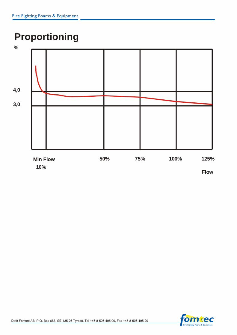
4,0
3,0
70 1750 3500 5260 7000Flow
%Proporioning

WRP 8” BT WIDE RANGE PROPORTIONER
Document Wrp 10 bt.doc / Ver 1:2
FEATURES • Fixed proportioning ratio
1%, 3% or 6% • Water flow 200 - 15,000
lpm • Between flange
construction • Suitable for ARC foam
concentrates • Easy to install
Application Fixed foam systems where a variable flow rate can occur, such as in sprinkler systems or multiple deluge systems.
Recommended Foam All types of foam concentrates with induction rates of 1%, 3% or 6% can be used. For ARC (alcohol resistant) foam concentrate a special calibration is necessary and should be mentioned when ordering.
Operation The WRP can be installed horizon-tally or vertically with a minimum pipe length of 5 times the diameter before and 3 times after the WRP. The foam inlet is connected to the bladder tank. The operating temperature should be above 0°C. Make sure that the pressure loss over the foam concentrate line from the bladder tank does not exceed 0,3 bar. The proportioning ratio is constant over the whole flow range.
Key data The Wide Range Proportioner, WRP, for bladdertanks offers an exact pre-settled proportioning ratio of 1%, 3% or 6% over a wide water flow range between 200 lpm and 15000 lpm. The maximum pressure loss is not more than 2,8 bars at 12000 lpm flow. The foam inlet is equipped with a non-return valve to prevent water from going back into the bladder tank.
Technical Data
Model WRP 8” BT
Size DN 200
Foam inlet female R 2½”
Flow range 150 – 15000 lpm
Proportioning rate (pre-calibrated)
1%, 3% or 6%
Inlet pressure (max) 16 bar
Inlet pressure (min) 5 bar
Pipe length upstream 1000 mm
Pipe length downstream 1000 mm
Flange type DIN PN16
Between flange proportions 88 mm
Height 360 mm
Weight 40 kg
Material Bronze, Compatible with all foam concentrates
Dafo Fomtec AB, P.O. Box 683, SE-135 26 Tyresö, Sweden, Tel +46 8-506 405 00, Fax +46 8-506 405 29

Dafo Fomtec AB, P.O. Box 683, SE-135 26 Tyresö, Sweden, Tel +46 8-506 405 00, Fax +46 8-506 405 29
PressuredropBAR
Flow
2,0
1,0
15000150L/min
7500
3,04,0
%
200 3750 7500 11250 15000Flow
Proportioning

WRP 10” BT WIDE RANGE PROPORTIONER
Document Wrp 10 bt.doc / Ver 1:2
Dafo Fomtec AB, P.O. Box 683, SE-135 26 Tyresö, Sweden, Tel +46 8-506 405 00, Fax +46 8-506 405 29
FEATURES • Fixed proportioning ratio
1%, 3% or 6% • Water flow 200 - 15,000
lpm • Between flange
construction • Suitable for ARC foam
concentrates • Easy to install
Application Fixed foam systems where a variable flow rate can occur, such as in sprinkler systems or multiple deluge systems.
Recommended Foam All types of foam concentrates with induction rates of 1%, 3% or 6% can be used. For ARC (alcohol resistant) foam concentrate a special calibration is necessary and should be mentioned when ordering.
Operation The WRP can be installed horizon-tally or vertically with a minimum pipe length of 5 times the diameter before and 3 times after the WRP. The foam inlet is connected to the bladder tank. The operating temperature should be above 0°C. Make sure that the pressure loss over the foam concentrate line from the bladder tank does not exceed 0,3 bar. The proportioning ratio is constant over the whole flow range.
Key Data The Wide Range Proportioner, WRP, for bladdertanks offers an exact pre-settled proportioning ratio of 1%, 3% or 6% over a wide water flow range between 200 lpm and 15000 lpm. The maximum pressure loss is not more than 2,8 bars at 12000 lpm flow. The foam inlet is equipped with a non-return valve to prevent water from going back into the bladder tank.
Technical Data Model WRP 10” BT
Size DN 250
Foam inlet female R 2 ½” (6% 3”)
Flow range 200 – 20 000 lpm
Proportioning rate (pre-calibrated)
1%, 3% or 6%
Inlet pressure (max) 16 bar
Inlet pressure (min) 5 bar
Pipe length upstream 2500 mm,
Pipe length downstream 2500 mm
Flange type DIN PN16
Between flange proportions 100 mm
Height 430 mm
Weight 65 kg
Material Bronze, Compatible with all foam Concentrates

Dafo Fomtec AB, P.O. Box 683, SE-135 26 Tyresö, Sweden, Tel +46 8-506 405 00, Fax +46 8-506 405 29
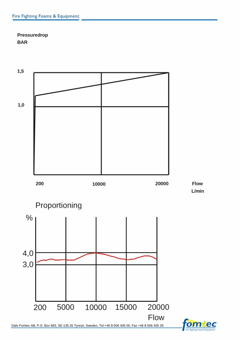
PressuredropBAR
Flow
1,5
1,0
20000200L/min
10000
3,04,0
200 5000 10000 15000 20000Flow
Proportioning%

WRP 6" FP WIDE RANGE PROPORTIONER
Document Wrp 6 fp / Ver 1:2
FEATURES • Fixed proportioning ratio
1%, 3% or 6% • Water flow 70 - 7,000 lpm • Between flange
construction • Suitable for ARC foam
concentrates • Easy to install • Accurate balance valve
Application Fixed foam systems where a variable flow rate can occur, such as in sprinkler systems or multiple deluge systems.
Recommended Foam All types of foam concentrates with induction rates of 1%, 3% or 6% can be used. For AR (alcohol resistant) foam concentrate a special calibration is necessary and should be mentioned when ordering.
Operation The WRP 6” FP is designed to work with Foam Pumps and can be installed horizon-tally or vertically with a minimum pipe length of 5 times the diameter before and 3 times after the WRP. The foam inlet is connected to the foam pump. The operating temperature should be above 0°C. The proportioning ratio is constant over the whole flow range.
Key data The Wide Range Proportioner, WRP, for foam pumps offers an exact pre-settled proportioning ratio of 1%, 3% or 6% over a wide water flow range between 70 lpm and 7,000 lpm. The maximum pressure loss is not more than 2.3 bars at 7,000 lpm flow. The foam and the water line are connected to a balance valve that guarantees the pressure difference between water and foam concentrate.
Technical Data
Model WRP 6” FP
Size DN 150
Foam inlet female R 2”
Flow range 70 - 7 000 lpm
Proportioning rate (pre-calibrated)
1%, 3% or 6%
Inlet pressure (max) 16 bar
Inlet pressure (min) 5 bar
Pipe length upstream 750 mm
Pipe length downstream 750 mm
Flange type DIN PN16
Between flange proportions 69 mm
Height 330 mm
Weight 16 kg
Material Bronze, Compatible with all foam concentrates
Dafo Fomtec AB, P.O. Box 683, SE-135 26 Tyresö, Sweden, Tel +46 8-506 405 00, Fax +46 8-506 405 29

Dafo Fomtec AB, P.O. Box 683, SE-135 26 Tyresö, Sweden, Tel +46 8-506 405 00, Fax +46 8-506 405 29
2,0
1,0
70 3500 7000 FlowL/min
PressuredropDrop
4,0
3,0
70 1750 3500 5260 7000Flow
%Proporioning

WRP 8” FP WIDE RANGE PROPORTIONER
Document Wrp 8 fp / Ver 1:2
FEATURES • Fixed proportioning ratio
1%, 3% or 6% • Water flow 200 -15,000 lpm • Between flange
construction • Suitable for ARC foam
concentrates • Easy to install • Accurate balance valve
Application Fixed foam systems where a variable flow rate can occur, such as in sprinkler systems or multiple deluge systems.
Recommended Foam All types of foam concentrates with induction rates of 1%, 3% or 6% can be used. For ARC (alcohol resistant) foam concentrate a special calibration is necessary and should be mentioned when ordering.
Operation The WRP 8” FP is designed to work with Foam Pumps and can be installed horizon-tally or vertically with a minimum pipe length of 5 times the diameter before and 3 times after the WRP. The foam inlet is connected to the foam pump. The operating temperature should be above 0°C. The proportioning ratio is constant over the whole flow range.
Key Data The Wide Range Proportioner, WRP, for Foam Pumps offers an exact pre-settled proportioning ratio of 1%, 3% or 6% over a wide water flow range between 200 lpm and 15000 lpm. The maximum pressure loss is not more than 2,8 bars at 12000 lpm flow. The foam inlet is equipped with a non-return valve to prevent water from going back into the storage tank.
Technical Data Model WRP 8” FP
Size DN 200
Foam inlet female R 2½”
Flow range 150 – 15000 lpm
Proportioning rate (pre-calibrated)
1%, 3% or (6%*)
Inlet pressure (max) 16 bar
Inlet pressure (min) 5 bar
Pipe length upstream 1000 mm
Pipe length downstream 1000 mm
Flange type DIN PN16
Between flange proportions 88 mm
Height 430 mm
Weight 48 kg
Material Bronze, Compatible with all foam concentrates
Dafo Fomtec AB, P.O. Box 683, SE-135 26 Tyresö, Sweden, Tel +46 8-506 405 00, Fax +46 8-506 405 29

Dafo Fomtec AB, P.O. Box 683, SE-135 26 Tyresö, Sweden, Tel +46 8-506 405 00, Fax +46 8-506 405 29
PressuredropBAR
Flow
2,0
1,0
15000150L/min
7500
3,04,0
%
200 3750 7500 11250 15000Flow
Proportioning

WRP 10” FP WIDE RANGE PROPORTIONER
Document Wrp 10 fp / Ver 1:2
FEATURES • Fixed proportioning ratio
1%, 3% or 6% • Water flow 200 -20,000 lpm • Between flange
construction • Suitable for ARC foam
concentrates • Easy to install • Accurate balance valve
Application Fixed foam systems where a variable flow rate can occur, such as in sprinkler systems or multiple deluge systems.
Recommended Foam All types of foam concentrates with induction rates of 1%, 3% or 6% can be used. For ARC (alcohol resistant) foam concentrate a special calibration is necessary and should be mentioned when ordering.
Operation The WRP 10” FP is designed to work with Foam Pumps and can be installed horizon-tally or vertically with a minimum pipe length of 5 times the diameter before and 3 times after the WRP. The foam inlet is connected to the foam pump. The operating temperature should be above 0°C. The proportioning ratio is constant over the whole flow range.
Key Data The Wide Range Proportioner, WRP, for Foam Pumps offers an exact pre-settled proportioning ratio of 1%, 3% or 6% over a wide water flow range between 200 lpm and 15000 lpm. The maximum pressure loss is not more than 2,8 bars at 12000 lpm flow. The foam inlet is equipped with a non-return valve to prevent water from going back into the storage tank.
Technical Data
Model WRP 10” FP
Size DN 250
Foam inlet female R 2 ½”
Flow range 200 – 20 000 lpm
Proportioning rate (pre-calibrated)
1%, 3% or( 6%**)
Inlet pressure (max) 16 bar
Inlet pressure (min) 5 bar
Pipe length upstream 2500 mm,
Pipe length downstream 2500 mm
Flange type DIN PN16
Between flange proportions 100 mm
Height 530 mm
Weight 73 kg
Material Bronze,Compatible with all foam concentrate
Dafo Fomtec AB, P.O. Box 683, SE-135 26 Tyresö, Sweden, Tel +46 8-506 405 00, Fax +46 8-506 405 29
Dafo Fomtec AB, P.O. Box 683, SE-135 26 Tyresö, Sweden, Tel +46 8-506 405 00, Fax +46 8-506 405 29
Pressuredrop
BAR
Flow
1,5
1,0
20000200L/min
10000
3,04,0
200 5000 10000 15000 20000Flow
Proportioning%