foamglas for floors foamglas t4, s3and f f2 … foamglas® cellular glass insulation can be used to...
TRANSCRIPT
Pittsburgh Corning (UK) Limited assumes no responsibility for errors in,or misinterpretation of the information contained in this leaflet or in itsuse. Pittsburgh Corning (UK) Limited also retains the right to amendtechnical specifications without prior notice.
Designed and Produced by SEL Ltd. Birmingham.
Pittsburgh Corning (UK) Limited63 Milford Road, ReadingBerkshire RG1 8LGTel: 0118 950 0655 Fax: 0118 950 9019email: [email protected]
FOAMGLAS® and PC are registered trademarks in the USA and othercountries. We reserve the rights of reproduction or translation, in whole orpart, in all countries including the CIS.
F2.02.05
USE OF FOAMGLAS®
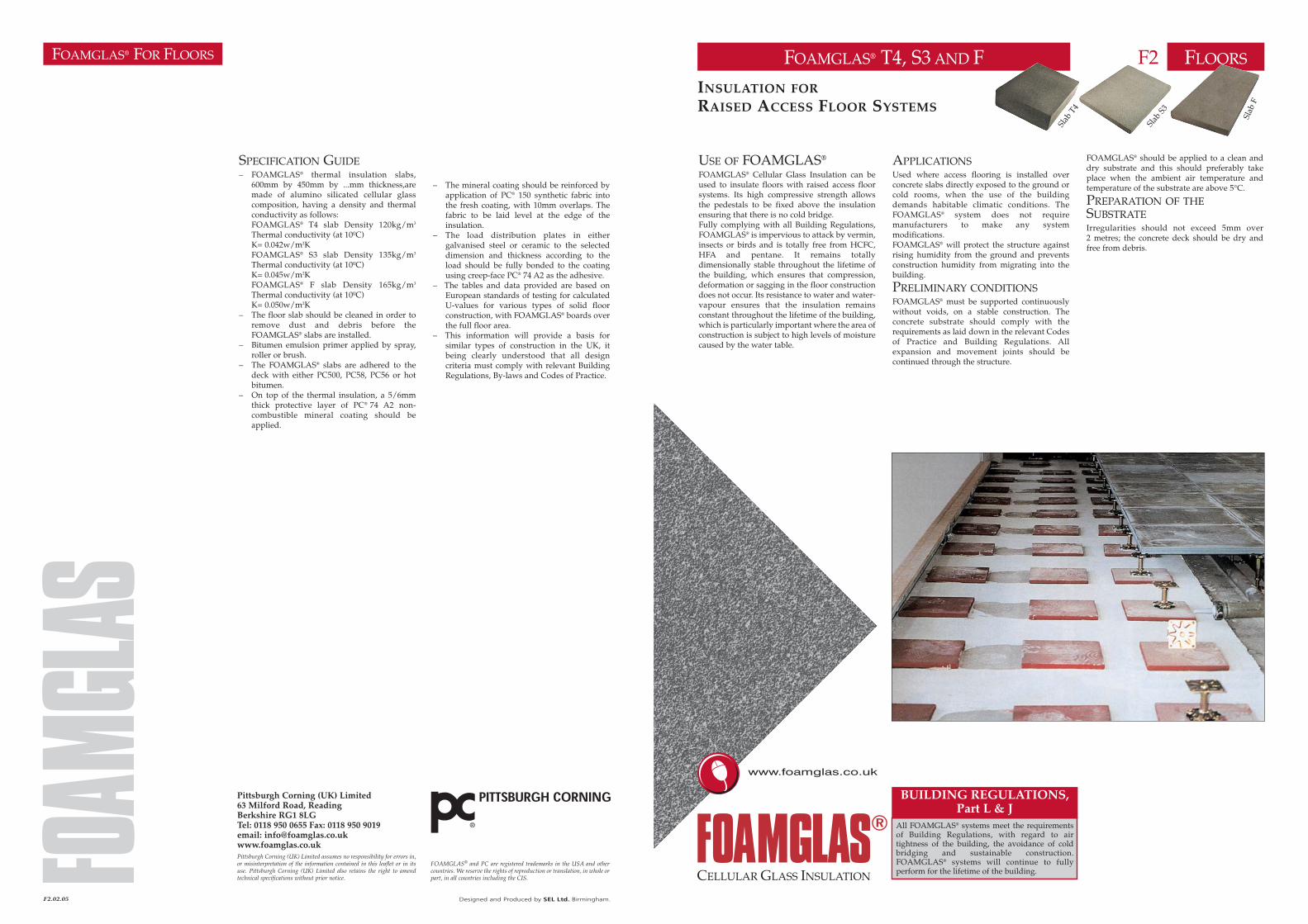
FOAMGLAS® Cellular Glass Insulation can beused to insulate floors with raised access floorsystems. Its high compressive strength allowsthe pedestals to be fixed above the insulationensuring that there is no cold bridge.Fully complying with all Building Regulations,FOAMGLAS® is impervious to attack by vermin,insects or birds and is totally free from HCFC,HFA and pentane. It remains totallydimensionally stable throughout the lifetime ofthe building, which ensures that compression,deformation or sagging in the floor constructiondoes not occur. Its resistance to water and water-vapour ensures that the insulation remainsconstant throughout the lifetime of the building,which is particularly important where the area ofconstruction is subject to high levels of moisturecaused by the water table.
FOAMGLAS® T4, S3 AND F FLOORSF2INSULATION FOR
RAISED ACCESS FLOOR SYSTEMS
APPLICATIONSUsed where access flooring is installed overconcrete slabs directly exposed to the ground orcold rooms, when the use of the buildingdemands habitable climatic conditions. TheFOAMGLAS® system does not requiremanufacturers to make any systemmodifications.FOAMGLAS® will protect the structure againstrising humidity from the ground and preventsconstruction humidity from migrating into thebuilding.
PRELIMINARY CONDITIONSFOAMGLAS® must be supported continuouslywithout voids, on a stable construction. Theconcrete substrate should comply with therequirements as laid down in the relevant Codesof Practice and Building Regulations. Allexpansion and movement joints should becontinued through the structure.
CELLULAR GLASS INSULATION
www.foamglas.co.uk
FOAMGLAS® FOR FLOORS
SPECIFICATION GUIDE– FOAMGLAS® thermal insulation slabs,
600mm by 450mm by ...mm thickness,aremade of alumino silicated cellular glasscomposition, having a density and thermalconductivity as follows:FOAMGLAS® T4 slab Density 120kg/m3
Thermal conductivity (at 10ºC)K= 0.042w/m2KFOAMGLAS® S3 slab Density 135kg/m3
Thermal conductivity (at 10ºC)K= 0.045w/m2KFOAMGLAS® F slab Density 165kg/m3
Thermal conductivity (at 10ºC)K= 0.050w/m2K
– The floor slab should be cleaned in order toremove dust and debris before theFOAMGLAS® slabs are installed.
– Bitumen emulsion primer applied by spray,roller or brush.
– The FOAMGLAS® slabs are adhered to thedeck with either PC500, PC58, PC56 or hotbitumen.
– On top of the thermal insulation, a 5/6mmthick protective layer of PC® 74 A2 non-combustible mineral coating should beapplied.
– The mineral coating should be reinforced byapplication of PC® 150 synthetic fabric intothe fresh coating, with 10mm overlaps. Thefabric to be laid level at the edge of theinsulation.
– The load distribution plates in eithergalvanised steel or ceramic to the selecteddimension and thickness according to theload should be fully bonded to the coatingusing creep-face PC® 74 A2 as the adhesive.
– The tables and data provided are based onEuropean standards of testing for calculatedU-values for various types of solid floorconstruction, with FOAMGLAS® boards overthe full floor area.
– This information will provide a basis forsimilar types of construction in the UK, itbeing clearly understood that all designcriteria must comply with relevant BuildingRegulations, By-laws and Codes of Practice.
FOAMGLAS® should be applied to a clean anddry substrate and this should preferably takeplace when the ambient air temperature andtemperature of the substrate are above 5°C.
PREPARATION OF THESUBSTRATEIrregularities should not exceed 5mm over2 metres; the concrete deck should be dry andfree from debris.
Slab
F
Slab
T4
Slab
S3
BUILDING REGULATIONS,Part L & J
All FOAMGLAS® systems meet the requirementsof Building Regulations, with regard to airtightness of the building, the avoidance of coldbridging and sustainable construction.FOAMGLAS® systems will continue to fullyperform for the lifetime of the building.
FOAMGLAS® FOR FLOORS
DESCRIPTION OF SYSTEMDependent on the eventual load requirements,FOAMGLAS® slabs T4, S3 or F should be bondedto the concrete deck using PC500, PC58, PC56 orhot bitumen.A layer of PC® 74 A2 non-combustible mineralcoating (thickness 5/6mm) is applied to theinsulation surface followed by a layer of PC® 150reinforced synthetic fabric.For load distribution, steel plates (of differentthicknesses and sizes - see tables opposite) arelaid out and fully bonded to the FOAMGLAS®insulation using PC® 74 A2. Ceramic plates canalso be used, see table 4.
THICKNESS OF FOAMGLAS®
T4, S3 AND FFOAMGLAS® will protect the construction frominterstitial condensation when the followingcriteria are not exceeded:– temperature in rooms above the floor ≤ 18°C– relative humidity in rooms ≤ 50%– surface temperature of underside of floor at≤ 5°CThe table opposite indicates the minimumthicknesses required to meet Part L & J of the UKBuilding Regulations (April 2002) dependentupon building usage.
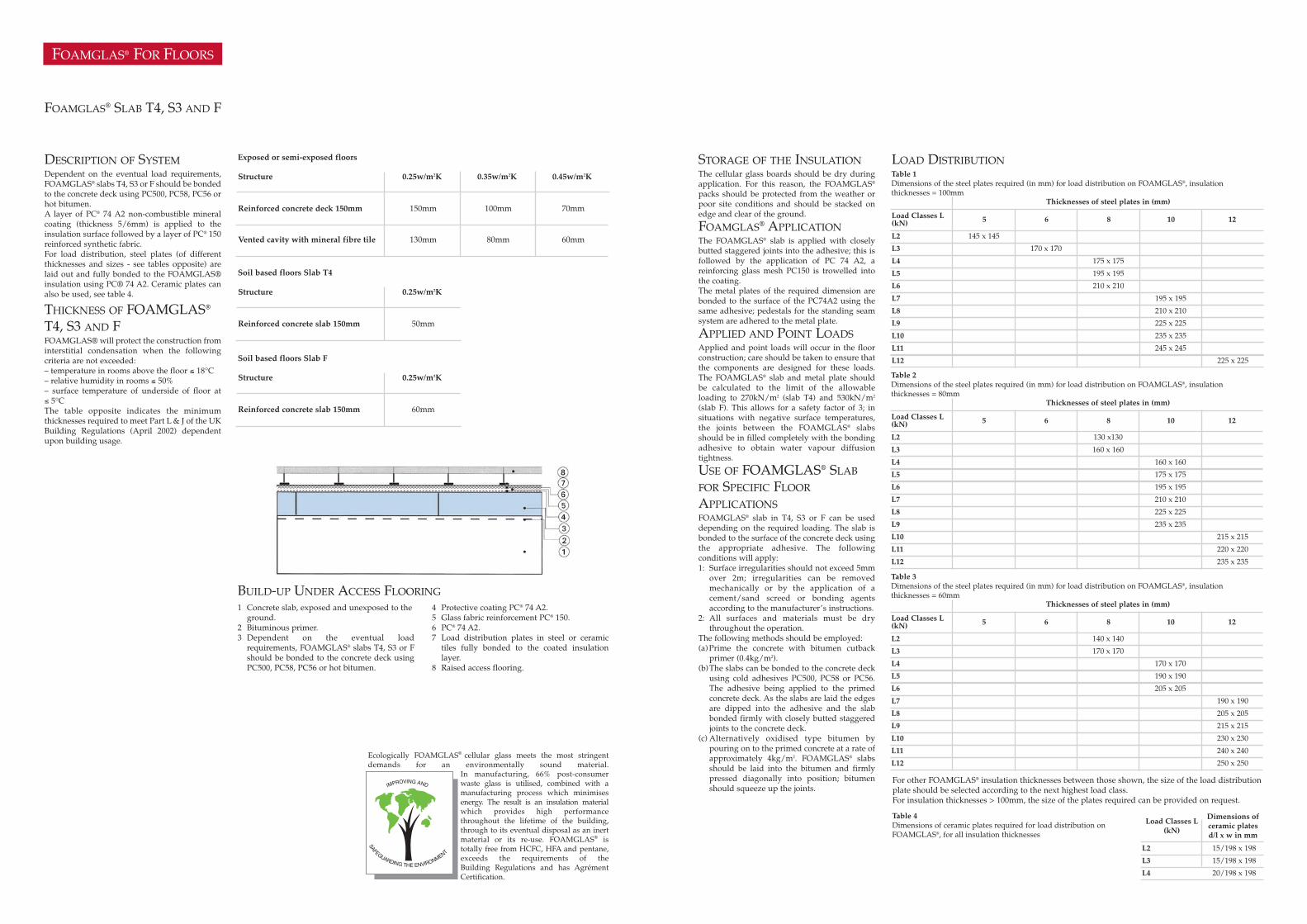
BUILD-UP UNDER ACCESS FLOORING4 Protective coating PC® 74 A2.5 Glass fabric reinforcement PC® 150.6 PC® 74 A2.7 Load distribution plates in steel or ceramic
tiles fully bonded to the coated insulationlayer.
8 Raised access flooring.
1 Concrete slab, exposed and unexposed to the ground.
2 Bituminous primer.3 Dependent on the eventual load
requirements, FOAMGLAS® slabs T4, S3 or Fshould be bonded to the concrete deck usingPC500, PC58, PC56 or hot bitumen.
Ecologically FOAMGLAS® cellular glass meets the most stringentdemands for an environmentally sound material.
In manufacturing, 66% post-consumerwaste glass is utilised, combined with amanufacturing process which minimisesenergy. The result is an insulation materialwhich provides high performancethroughout the lifetime of the building,through to its eventual disposal as an inertmaterial or its re-use. FOAMGLAS® istotally free from HCFC, HFA and pentane,exceeds the requirements of theBuilding Regulations and has AgrémentCertification.
STORAGE OF THE INSULATIONThe cellular glass boards should be dry duringapplication. For this reason, the FOAMGLAS®
packs should be protected from the weather orpoor site conditions and should be stacked onedge and clear of the ground.
FOAMGLAS® APPLICATIONThe FOAMGLAS® slab is applied with closelybutted staggered joints into the adhesive; this isfollowed by the application of PC 74 A2, areinforcing glass mesh PC150 is trowelled intothe coating.The metal plates of the required dimension arebonded to the surface of the PC74A2 using thesame adhesive; pedestals for the standing seamsystem are adhered to the metal plate.
APPLIED AND POINT LOADSApplied and point loads will occur in the floorconstruction; care should be taken to ensure thatthe components are designed for these loads.The FOAMGLAS® slab and metal plate shouldbe calculated to the limit of the allowableloading to 270kN/m2 (slab T4) and 530kN/m2
(slab F). This allows for a safety factor of 3; insituations with negative surface temperatures,the joints between the FOAMGLAS® slabsshould be in filled completely with the bondingadhesive to obtain water vapour diffusiontightness.
USE OF FOAMGLAS® SLAB
FOR SPECIFIC FLOOR
APPLICATIONSFOAMGLAS® slab in T4, S3 or F can be useddepending on the required loading. The slab isbonded to the surface of the concrete deck usingthe appropriate adhesive. The followingconditions will apply:1: Surface irregularities should not exceed 5mm
over 2m; irregularities can be removedmechanically or by the application of acement/sand screed or bonding agentsaccording to the manufacturer’s instructions.
2: All surfaces and materials must be drythroughout the operation.
The following methods should be employed:(a)Prime the concrete with bitumen cutback
primer (0.4kg/m2). (b)The slabs can be bonded to the concrete deck
using cold adhesives PC500, PC58 or PC56.The adhesive being applied to the primedconcrete deck. As the slabs are laid the edgesare dipped into the adhesive and the slabbonded firmly with closely butted staggeredjoints to the concrete deck.
(c) Alternatively oxidised type bitumen bypouring on to the primed concrete at a rate ofapproximately 4kg/m2. FOAMGLAS® slabsshould be laid into the bitumen and firmlypressed diagonally into position; bitumenshould squeeze up the joints.
LOAD DISTRIBUTION0.25w/m2KStructure
Reinforced concrete deck 150mm
FOAMGLAS® SLAB T4, S3 AND F
150mm
0.35w/m2K
100mm
0.45w/m2K
70mm
Vented cavity with mineral fibre tile 130mm 80mm 60mm
Exposed or semi-exposed floors
0.25w/m2KStructure
Soil based floors Slab T4
Reinforced concrete slab 150mm 50mm
0.25w/m2KStructure
Soil based floors Slab F
Reinforced concrete slab 150mm 60mm
Thicknesses of steel plates in (mm)
5 6 8 10 12Load Classes L(kN)
L2 145 x 145
L3 170 x 170
L4 175 x 175
L5 195 x 195
L6 210 x 210
L7 195 x 195
L8 210 x 210
L9 225 x 225
L10 235 x 235
L11 245 x 245
L12 225 x 225
For other FOAMGLAS® insulation thicknesses between those shown, the size of the load distributionplate should be selected according to the next highest load class.For insulation thicknesses > 100mm, the size of the plates required can be provided on request.
Table 1Dimensions of the steel plates required (in mm) for load distribution on FOAMGLAS®, insulationthicknesses = 100mm
Thicknesses of steel plates in (mm)
5 6 8 10 12Load Classes L(kN)
L2 130 x130
L3 160 x 160
L4 160 x 160
L5 175 x 175
L6 195 x 195
L7 210 x 210
L8 225 x 225
L9 235 x 235
L10 215 x 215
L11 220 x 220
L12 235 x 235
Table 2Dimensions of the steel plates required (in mm) for load distribution on FOAMGLAS®, insulationthicknesses = 80mm
Thicknesses of steel plates in (mm)
5 6 8 10 12
Load Classes L(kN)
Dimensions ofceramic platesd/l x w in mm
Load Classes L(kN)
L2 140 x 140
L3
L4 170 x 170
L5 190 x 190
L2
L3
15/198 x 198
15/198 x 198
L6 205 x 205
L7 190 x 190
L8 205 x 205
L9 215 x 215
L10 230 x 230
L11 240 x 240
L12 250 x 250
L4 20/198 x 198
Table 3Dimensions of the steel plates required (in mm) for load distribution on FOAMGLAS®, insulationthicknesses = 60mm
Table 4Dimensions of ceramic plates required for load distribution onFOAMGLAS®, for all insulation thicknesses
170 x 170