“focused geologic mapping and structural analysis of the...
TRANSCRIPT

University of Nevada, Reno
“Focused geologic mapping and structural analysis of the southern Eureka mining district; assessing structural controls and spatial patterns of mineralization”
A thesis submitted in partial fulfillment of the requirements for the degree of Master of Science in Geology
By
Russell Vincent Di Fiori
Sean Long, PhD, Advisor
May, 2014

We recommend that the thesis prepared under our supervision by
RUSSELL V. DI FIORI
Entitled
“Focused Geologic Mapping And Structural Analysis Of The Southern Eureka Mining District; Assessing Structural Controls And Spatial Patterns Of
Mineralization”
be accepted in partial fulfillment of the requirements for the degree of
MASTER OF SCIENCE
Sean P. Long, Phd, Advisor
John Muntean, Phd, Committee Member
William Hammond, Phd, Graduate School Representative
David W. Zeh, Ph.D., Dean, Graduate School
May, 2014
THE GRADUATE SCHOOL
i
Abstract
The Eureka Mining District is located in the northern part of the Fish Creek Range in east-central
Nevada. In this study, 1:6,000-scale geologic mapping and structural analysis were performed in the
southern part of the district in order to identify structural controls on mineralization. This project bridges
a gap between recent regional-scale mapping studies and detailed (<1:500) mapping performed in an
active gold exploration campaign. A geologic map of a ~3.5 km (east-west) by ~8 km (north-south)
region was generated, along with five deformed and restored cross-sections that illustrate the post- and
pre-extensional deformation geometry. The stratigraphy of the map area consists of ca. 4 km of Cambrian
to Devonian rocks that are dominated by carbonates, which, in turn, are unconformably overlain and
intruded by Late Eocene silicic volcanic rocks.
The map area is composed of four distinct structural systems, including Early Cretaceous
contractional structures which include the Eureka culmination and blind Ratto Canyon thrust, and three
separate sets of normal faults: 1) 1st-order, km-scale offset, down-to-the-west normal faults, which
include the Lookout Mountain and Dugout Tunnel faults, 2) 2nd-order, 10’s to 100’s meter-offset normal
faults, including the Rocky Canyon, Oswego, and East Ratto Ridge fault systems, and 3) a 3rd-order set of
sub-meter scale offset, east-striking extensional faults that offset the presumed Late Eocene jasperoid
bodies. The 1st- and 2nd-order faulting can be bracketed between Late Cretaceous (ca. 86 Ma), the age of
contact metamorphism in northern Rocky Canyon that is cut by the Dugout Tunnel fault, and Late Eocene
(ca. 37 Ma), based on the overlapping relationship of a sub-volcanic unconformity.
The Eureka district is characterized by silver-lead polymetallic carbonate replacement and Carlin-
type gold deposits, which are the two primary deposit-types in the project area. In addition to lithology
and structure, specific types of hydrothermal alteration and mineralization were mapped, including

ii
silicification, decarbonatization, dolomitization, quartz/calcite-veining, argillization, and the introduction
of sulfides and their limonite weathering products. Through this method two distinct mineralization
events were identified. Polymetallic mineralization, characterized by dolomitization, argillization, and
quartz-veining, resides in the northern part of the map area in Rocky Canyon. It is interpreted to be
genetically-related to Late Cretaceous granitic magmatism, which indicates that it pre-dates timing
extension along 1st- and 2nd-order normal faults. The Carlin-type mineralization occurs as a series of
deposits, mainly along Ratto Ridge. The deposits are associated with strong decarbonatization, strong
silicification and jasperoid formation, and argillization. This Carlin-type deposit is temporally
constrained to be pre- or syn-Late Eocene, due to overlap and intrusion of dated silicic-volcanic rocks.
The map area contains a kilometer-scale, synthetically-faulted relay-ramp of 2nd-order faults that
transfer slip between the 1st-order, synthetic Dugout Tunnel and Lookout Mountain faults. Within
accommodation zones, wall-damage zones are predicted to exert a first-order control on hydrothermal
fluid pathways and localization of mineralization. The footwall of the Lookout Mountain fault contains a
set of antithetic, 2nd-order normal faults, the East Ratto Ridge fault system, which is interpreted as a wall-
damage zone that was fundamentally responsible for controlling fluid-flow that led to Carlin-type
mineralization.

iii
Acknowledgements
Foremost I thank my advisor, Dr. Sean Long, whom with infinite patience, constructive criticism,
and unparalleled passion for ‘bigger-picture geology’, has taught me to distinguish the ‘forest from the
trees’. I also thank Dr. John Muntean for his guidance and assistance with my thesis, and reiterating
complex theories and processes in a simplified manner in a way my mind could comprehend. Thank you
Gary Edmondo for your facilitation of this project and taking a chance on a naïve geologist that really just
wanted to map rocks. The entire NBMG cartography team, especially Jennifer Mauldin, whom, without
her I would still be lost somewhere in ArcMAP, pulling my hair out. I would also like to thank Dr. Bill
Hammond for coming to the rescue and taking the third committee member seat on such short notice. I
wish to thank Timberline Resources for their aid in funding and allowing me to utilize their property for
such an awesome and rewarding project. A big thank you goes out to my fellow graduate students at
UNR. Specifically, Ryan Anderson, Greg Dering, Andrew Sadowski, Sergey Konyshev, Melissa Penfold,
and Ben Parrish. All of whom have offered insightful conversation and instigated new thoughts that aided
in the completion and direction of this thesis. I would like to thank my parents for being there for
support, offering words of encouragement when the light at the end of the tunnel seemed far and away.
And finally, thanks to Jesslyn Starnes, my best friend and compatriot who kept me well fed and inspired
through these past couple of years.

iv
Table of Contents
1. Introduction 1 Objectives
2. Geologic Setting and Tectonic Framework 4 Tectonic evolution and regional geology
3. Methods 8 3.1 Geologic and Alteration Mapping 3.2 Cross-Sections
4. Stratigraphy 11
5. Structural Framework 22 5.1 Contractional Structures 5.2 Extensional Structures
6. Alteration/Mineralization 30 6.1 Background on Carlin-type and Polymetallic-type deposits 6.2 Alteration and mineralization in the map area
7. Discussion 39
7.1 Structural evolution of the map area 7.2 Mineralization: spatial patterns and structural controls 7.3 Testing predictive structural models of mineralization in accommodation zones
8. Conclusions 46
References Cited 48 Plate 1 Map Figures 6A-E Cross-Sections

v
List of Figures
1. Introduction Figure 1.Map area relative to major gold trends 2 Figure 2.Focussed map location 3
2. Geologic Setting and Tectonic Framework Figure 3.Study area within tectonic framework 5 Figure 4. Stratigraphy of map area 6
3. Methods Figure 5.Structural Trends and geographic points 9
*Figure’s 6A-E are found accompanying Plate 1 at the end.
4. Stratigraphy
5. Structural Framework Figure 7. Structural Systems of map area 23 Figure 8. Annotated photograph of Rocky Canyon 28
6. Alteration/Mineralization Figure 9 Simplified alteration map 34 Figure 10. Block diagram; structural evolution of map area 37-38
7. Discussion Figure11. Gold grade thickness map 42 Figure12. Schematic cross-section of Lookout Mountain 43 Figure 13. Schematic diagram of breached-relay-ramp 44 Figure 14. Schematic diagram of wall damage zone 44
8. Conclusions Plate 1
1
1. Introduction
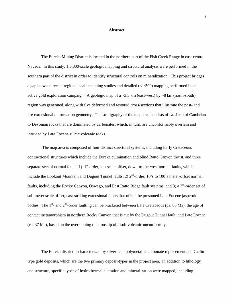
The Eureka mining district occupies the southern tip of the Battle Mountain – Eureka
trend of Carlin-type gold mineralization in east-central Nevada (Figure 1), and contains a series
of gold deposits (Nolan, 1962). Numerous geologic investigations of Carlin-type deposits have
determined that the geometry of gold orebodies commonly trend parallel to structures, such as
folds and faults (Peters, 2004), implying that mineralization is genetically-related to the
structures. The Eureka mining district hosts several Carlin-type gold deposits that occur in zones
of deformation that are spatially-associated with hydrothermal dissolution, and jasperoidal
breccia zones. The purpose of this study is to document structural controls on mineralization
within the southern part of the actively-explored and historically-developed Eureka mining
district.
Recent advances in understanding the large-scale structural geometry and deformation
history of the Eureka district by Long et al. (2012; 2014), and the results of a drilling campaign
by Timberline Resources, Corporation (TRC), a junior-scale gold company actively exploring the
district, as well as a collaborating partner in this research make a detailed evaluation of the
relationships between rock alteration and structural geometry at an economic scale both necessary
and timely. Identifying the structural controls on mineralization will assist in generating drill-
hole targets for new deposits and may lead to better understanding of Carlin-type mineralization
in general.
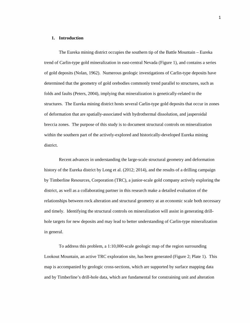
To address this problem, a 1:10,000-scale geologic map of the region surrounding
Lookout Mountain, an active TRC exploration site, has been generated (Figure 2; Plate 1). This
map is accompanied by geologic cross-sections, which are supported by surface mapping data
and by Timberline’s drill-hole data, which are fundamental for constraining unit and alteration
2
Figure 1. Map showing location of project area with respect to major gold trends in northeastern Nevada. Modified from Peters (2004) and Weber (2005).
3
Figure 2. Map showing location of project area, with areas of 7.5’ quadrangles shown for scale. Red outline represents map boundary, and yellow line represents U.S. Highway 50.
boundaries at depth. As a second step, the cross-sections are retro-deformed, with motions on
extensional faults removed, to assure viable geometries, and to illustrate the pre-extensional (and
assumed pre-mineralization) deformation geometry. An Au-grade thickness map was also
constructed in order to gain insight into how fault systems may have or may not have influenced
the distribution of ore. The map and cross-sections were used to generate a structural model to
help elucidate the temporal and spatial evolution of alteration and mineralization, and the degree
to which the structural architecture controlled primary hydrothermal fluid pathways
Finally, this project also provides the opportunity to test a structurally-framed model for
concentrated mineralization in accommodation zones between overlapping synthetic normal
faults. Predictions for mineralization outboard of the primary faults within accommodation and
damage zones, as outlined in Micklethwaite et al. (2010), Faulds (2011), and Micklethwaite

4
(2011), will be tested by cataloging scaling relationships of structures within an accommodation
zone within the study area, in conjunction with spatial patterns of alteration obtained through
alteration mapping using methods originally developed by the Anaconda Mining Company.
2. Geologic Setting and Tectonic Development
The Eureka mining district, and surrounding region of eastern Nevada, lies within the rifted
western margin of the North American craton (Cook and Corboy, 2004). During the early to mid-
Paleozoic, the Eureka region was situated on the distal edge of the continental shelf of the
Cordilleran passive margin basin, which was a vast carbonate platform (Stewart and Poole, 1974).
The Cambrian to Devonian stratigraphic section consists primarily of limestone and dolostone
interbedded with shale and sandstone (Figure 4) (e.g., Cook and Corboy, 2004). These carbonate
rocks, particularly the Cambrian section, serve as the dominant host rock for mineralization in the
district.
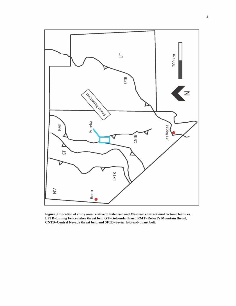
During the Late Devonian to Early Mississippian, the Antler orogeny, a contractional
deformational event involving eastward-vergent thrusting of deep-water sediments of the
Robert’s Mountain allochthon over the western edge of the continental shelf, took place to the
west of the map area (Figure 3) (Speed and Sleep, 1982). The Eureka region occupied a foreland
basin that subsided on the eastern margin of the allochthon, and sediment shed from the eroding
highlands shifted the sedimentation-style to the west, depositing carbonaceous silt, sand, and
conglomerate. This deposition is represented by a ~ 1.5 km-thick section of Mississippian
conglomerate and shale (Nolan et al., 1974).
5
Figure 3. Location of study area relative to Paleozoic and Mesozoic contractional tectonic features. LFTB=Luning Fencemaker thrust belt, GT=Golconda thrust, RMT=Robert’s Mountain thrust, CNTB=Central Nevada thrust belt, and SFTB=Sevier fold-and-thrust belt.

6
During the Jurassic-Cretaceous Cordilleran orogenic event, the Eureka mining district was
Figure 4. Stratigraphy of the map area

7
situated between the Jurassic Luning-Fencemaker thrust belt in western Nevada (Oldow, 1984;
Wyld, 2002), and the Jurassic-Cretaceous Sevier fold and thrust belt in Utah (Figure 3) (e.g.,
Armstrong, 1968; DeCelles, 2004). Uplift and erosion during the Sevier orogeny is interpreted to
be responsible for the erosion of any Mesozoic strata that would have been deposited prior to
eruption of Eocene-Oligocene volcanic rocks (Long, 2012). The Eureka region is situated within
the Central Nevada thrust belt (Taylor et al., 1993, Long, 2012), a system of north-striking
contractional structures which can be bracketed between Permian and Late Cretaceous (Taylor et
al., 2000), and in some places as Early Cretaceous (Long et al., 2014), The Central Nevada thrust
belt represents an internal part of the Sevier thrust belt. Long et al. (2014) proposed that the
large-scale structure of the Eureka mining district can be explained by Early Cretaceous growth
of a regional-scale anticlinal culmination associated with east-vergent motion on the blind Ratto
Canyon thrust, which is defined by a Cambrian over Silurian relationship in drill holes beneath
Lookout Mountain and Rocky Canyon, in the southern part of the map area (Figure 2).
This Cretaceous contractional deformation was followed by extension along several, large-
throw (100’s to 1000’s of meters) normal faults, which are bracketed between Late Cretaceous
and Late Eocene (Long et al., 2014). In the map area, the largest-offset (2,000 – 4,000 meters)
normal faults include the Dugout Tunnel and Lookout Mountain faults (Plate 1; Figures 7a-e).
These structures are superposed by multiple smaller-scale (10’s to 100’ of meters offset) normal
faults, generally striking north to north-east.
Cenozoic magmatism began at ca. 45 Ma in northeastern Nevada, and was part of a
southwestward-migrating belt of silicic magmatism called the Great Basin ignimbrite flare-up.
Ignimbrite flare-up magmatism was dominated by andesitic and dacitic lavas and
compositionally-similar intrusions (Henry, 2008). In the Eureka region, ignimbrite flare-up rocks
8
included Late Eocene (~37-33 Ma) silicic ash falls and flows, tuffs, and intrusive volcanic rocks
(Nolan et al., 1974; Long et al., 2014).
More recently, Nevada has been the site of regional extension associated with formation
of the Basin and Range extensional province. The Basin and Range is a product of the
extensional regime introduced by the establishment of the San Andreas transform fault system,
the active plate boundary between the North American plate and the Pacific plate, beginning in
the Early Miocene (Dickinson, 2006). The map area resides in the Fish Creek Range, and other
adjacent modern basins and valleys include the Diamond Mountains, Diamond Valley, the
Mountain Boy Range and the Mahogany Hills (Figure 2).
3. Methods
3.1. Geologic and Alteration Mapping
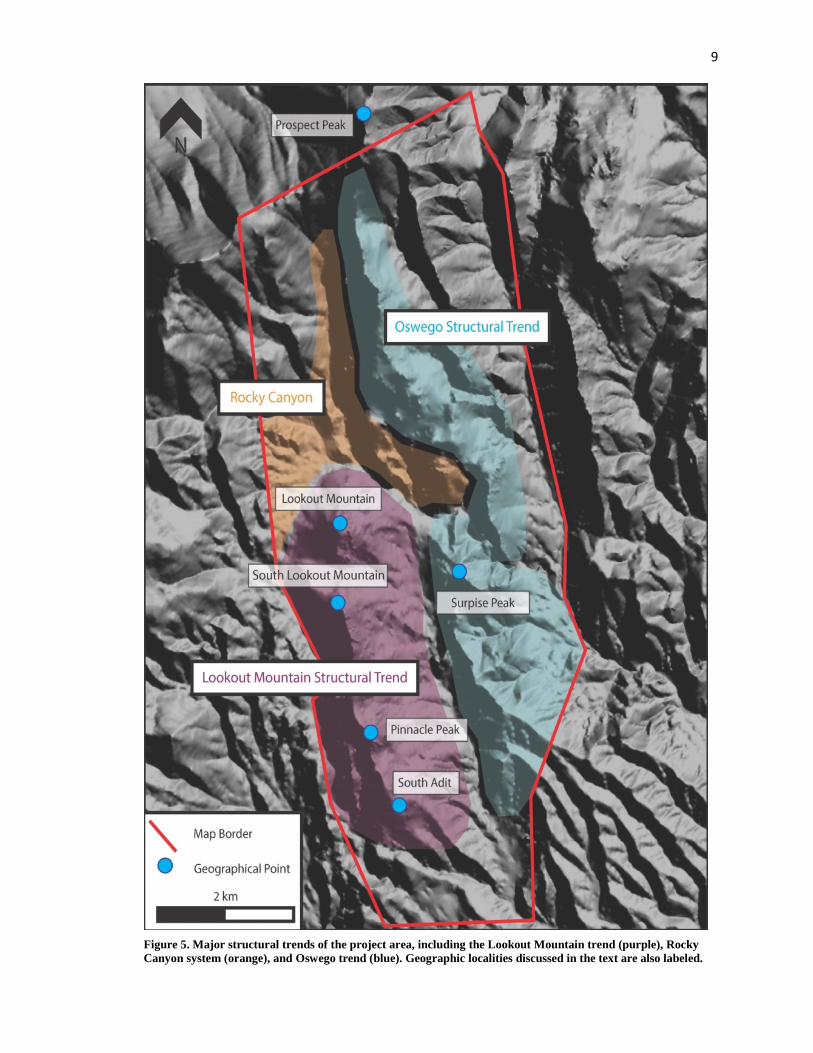
Geologic mapping of the Oswego and Lookout Mountain structural trends (Figure 5) was
conducted at a scale of 1:6,000, and is presented here at 1:10,000 (Plate 1). Field-based mapping
was supplemented by interpretation of 1:24,000 scale aerial photographs, and was completed on
hand-drafted overlays draped over 1:6,000 scale orthoimagery and topography. Drafting of the
overlays was completed in ArcMap 10.1 with annotations performed in Adobe Illustrator CS6.
The map area is ~3.5 km (east-west) by ~8 km (north-south), and is centered on TRC’s Lookout
Mountain exploration site, which lies at the northern end of the Fish Creek Range (Figure 2).
9
Figure 5. Major structural trends of the project area, including the Lookout Mountain trend (purple), Rocky Canyon system (orange), and Oswego trend (blue). Geographic localities discussed in the text are also labeled.

10
The location of the study area was chosen based on TRC’s existing exploration effort,
which is focused on areas of hydrothermal alteration with elevated concentrations of gold. The
map boundaries were chosen based on both the spatial extent of the structurally complex Rocky
Canyon, Lookout Mountain, and Oswego structural trends (Figure 5), as well the locations of
known occurrences of mineralization and exploration targets.
Similarities and differences in textures, outcrop character, weathering character,
composition, and local fossil assemblages were used to delineate stratigraphic units (Figure 4), as
originally defined by Nolan (1956; 1962) and Nolan et al. (1974).
Alteration mapping was completed as an additional overlay over geologic data using the
method originally developed by the Anaconda Mining Company (Einaudi, 1997). The Anaconda
mapping scheme is designed to record veining, replacement minerals, ore minerals, sulfide and
oxide minerals, and rock alteration in addition to lithology, structure, and geologic contacts, by
the use of representative colors, symbols, and shorthand notation (Brimhall, 2006). Specific
types of hydrothermal alteration and mineralization products that were mapped include jasperoid
(silicification of limestone), decarbonatization of carbonate host rock, carbonization, and
argillization, and sulfides (mainly pyrite) and their limonitic weathering products including
goethite, hematite, and jarosite. Alteration mapping focused specifically on hydrothermal
alteration and mineralization, as it was the primary mode of ore deposition in the study area.
3.2 Cross-Sections
The geologic map is accompanied by five deformed and restored geologic cross-sections
(Figures 6a-e), which are constrained by the surface map, data, including the locations of
structures and stratigraphic contacts, stratigraphic thicknesses, and apparent dip of strata. In

11
addition, the cross-sections are constrained by drill-hole data from TRC’s ongoing exploration
and development campaign, as well as drill-hole data from past exploration campaigns by
companies including Newmont, Echo Bay, Barrick, Staccato, and BH Minerals. The cross-
sections were drafted along transects perpendicular to the strike of major structures and the
dominant regional strike of bedding (Plate 1). The original versions of the cross-sections were
drafted by hand, and Adobe Illustrator CS6 was used in drafting and annotating the final sections.
*Figures 6A-E. Cross-Sections; deformed and retro-deformed. A: North Rocky Canyon, B: South Rocky Canyon, C: Lookout Mountain, D: South Lookout Mountain, and E: South Adit. Accompanying Plate 1 in back of thesis.
Regions of similar apparent dip on the cross-sections were used to define dip-domains.
The boundaries between adjacent dip domains were treated as kink-surfaces (e.g., Suppe, 1983),
and their orientation was determined by bisecting the intersection angle of the two domains. Dip
domains, line lengths, angles, and fault offsets were matched between the deformed and restored
cross-sections (Dahlstrom, 1969). In addition, eroded stratigraphy above the modern erosion
surface is drafted on the cross-sections. The versions of the cross-sections included in the text of
this thesis show both the deformed and restored versions, in order to illustrate fault paragenesis as
well as scaling relationships. The versions of the cross-sections in text also omit overlying
Quaternary and Tertiary volcanics from the erosion surface for simplicity.
4. Stratigraphy
The map area contains exposures of Paleozoic rocks ranging in age from Cambrian to
Devonian, and Cenozoic rocks, including late Eocene volcanics rocks and Quaternary deposits
(Figure 4).

12
Paleozoic rocks
Early Cambrian to Late Devonian rocks are exposed in the map-area, and have a
cumulative thickness of ~4.3 km (Figure 4). The true stratigraphic-thickness of shale-dominant
units (e.g. Secret Canyon shale, Ninemile Formation, Dunderberg shale) is difficult to determine
due to meter-scale folding and faulting.
Lithologic Descriptions
Dn - Nevada Formation (Lower-Middle Devonian)
Dbs - Bay State dolostone member (Middle Devonian): Fossiliferous, fine-medium
grained dolostone, which weathers gray to dark gray/brown, and brown to olive-gray
when freshly broken. Bedding is locally thin, massive, and uniform (Nolan, 1956).
Exhibits abundant characteristic white, elongate, cylindrical “spaghetti” corals
(Cladopora) as well as abundant, large (2-6 cm) Stringocephalus brachiopods. Bedding
is more distinct and color is typically lighter and more uniform than Dsm. Forms bluffy
and cliffy exposures. 700 feet thick.
Dsm - Sentinel Mountain dolostone member (Middle Devonian): Fine to coarse
grained, alternating medium gray-brown/yellow and light-gray weathering dolostone with
similar, to darker color on fresh surfaces (Nolan, 1956). Decameter to meter-scale strata-
bound color alternation is diagnostic: cm-scale mottling is common in light-gray, thick-
bedded, massive dolostone, and the medium gray-brown to yellowish-brown dolostone is
generally medium-thick bedded with rare interstitial laminations. Forms rugged, knobby
slopes and cliffs; petroliferous when broken. 450-700 feet thick.

13
Doc - Oxyoke Canyon sandstone member (Middle Devonian): Thick to very thick-
bedded, fine to medium-sand grained sized dolomitic sandstone with thin crystalline
dolomite interbeds (Nolan, 1956). Weathers light-grey, brown, and tan, and is tan to grey
when freshly broken. Interbedded dolomitic quartzose sandstone is fine to coarse-grained,
sub-angular to well-rounded, moderately graded, and commonly cross-bedded. Iron-
oxide staining parallel with bedforms is common. Forms cliffy to rugged exposures
depending on abundance of quartz-sandstone and dolomite. 350 feet thick.
Dsr - Sadler Ranch member (Lower Devonian): Fossiliferous packstone and wackestone,
weathers brown-grey to dark-grey, and grey-blue when fresh, and exhibits abundant Gasterocoma
bicuala two-hole crinoids (Johnson and Lane, 1969). Interbedded with crinoid-rich, finer-grained
gray to light gray limestone. Petroliferous odor when broken. Forms subdued slopes. 300 feet
thick.
Db - Bartine member of the McColley Canyon Formation (Lower Devonian): Fossiliferous
thin- to medium-bedded micrite. Weathers medium-grey to khaki-tan and dark grey when fresh.
Abundant fossil hash typically consists of shell and crinoid fragments; fossiliferous interstitial
packstones and wackestones are also common. Interbedded with tan to red (liesegang banding)
weathering, thin-bedded, silty limestone and siltstone. Outcrops poorly, forming platy, float-
covered slopes. Strong petroliferous odor when broken. 125-250 feet thick.
14
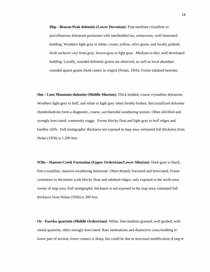
Dbp - Beacon Peak dolomite (Lower Devonian): Fine-medium crystalline to
porcellaneous dolostone packstone with interbedded tan, arenaceous, well-laminated
bedding. Weathers light gray to white, cream, yellow, olive green, and locally pinkish;
fresh surfaces vary from gray, brown-gray to light gray. Medium to thin, well-developed
bedding. Locally, rounded dolomite grains are observed, as well as local abundant
rounded quartz grains (both clastic in origin) (Nolan, 1956). Forms subdued benches.
Slm - Lone Mountain dolomite (Middle Silurian): Thick bedded, coarse crystalline dolostone.
Weathers light-grey to buff, and white to light grey when freshly broken. Recrystallized dolomite
rhombohedrons form a diagnostic, coarse, saccharoidal weathering texture. Often silicified and
strongly brecciated; commonly vuggy. Forms blocky float and light gray to buff ridges and
knobby cliffs. Full stratigraphic thickness not exposed in map area; estimated full thickness from
Nolan (1956) is 1,500 feet.
SOhc - Hanson Creek Formation (Upper Ordovician/Lower Silurian): Dark-gray to black,
fine-crystalline, massive-weathering dolostone. Often densely fractured and brecciated. Forms
centimeter to decimeter scale blocky float and subdued ridges; only exposed in the north-west
corner of map area. Full stratigraphic thickness is not exposed in the map area; estimated full
thickness from Nolan (1956) is 200 feet.
Oe - Eureka quartzite (Middle Ordovician): White, fine-medium grained, well-graded, well-
sorted quartzite; often strongly brecciated. Rare laminations and distinctive cross-bedding in
lower part of section; lower contact is sharp, but could be due to structural modification (Long et

15
al., 2012). Common fracture-controlled iron oxide (red-brown) staining. Coarse-grained sand and
interfingering conglomerate lenses are rare. Forms distinct white cliffs and prominent ridges and
weathers to large, rounded boulder-sized float. 400 feet thick.
Op - Pogonip Group (Lower-Middle Ordovician)
Oav: Antelope Valley Formation: Thin to thick bedded, bluish gray, fine-grained,
wackestone, and packstone with diagnostic very thin to thin tan to yellow silty partings
and abundant fossils, both in hash and as whole specimens. Coiled, cm-scale Maclurites
gastropods shells are diagnostic (Nolan, 1956). Local tan, brown, and white diagenetic
chert nodules; less chert in contrast with the Goodwin Formation. Outcrops well,
forming blocky ridges and slopes. Interfingering lower contact with Onm; at least 1,000
feet thick.
Onm - Ninemile Formation: Thin-bedded to platy, porcellaneous calcareous shale;
weathers tan-green to tan-grey and is olive green to green-tan when freshly broken
(Nolan, 1956). Surficial red-brown iron-staining is common. Interbeds of thin, planar
bedded gray limestone are common. Distinct from similar units by being arenaceous
(Nolan, 1956). Slope forming; does not crop out well. 300-400 feet thick.
Og - Goodwin limestone: Thick, well bedded limestone and wackestone with interbeds
of medium bedded, silty, fine–grained limestone weathering light to medium blue-gray

16
and dark gray when fresh (Nolan, 1956). Gray-brown, white, and black diagenetic chert
nodules are common in lower and upper parts of section (Nolan, 1956). Middle part of
section primarily consists of thinner-bedded limestone with undulating bedding with
common interstitial, thinly bedded silty carbonate layers. Abundant fossil hash; Kainella
trilobite is diagnostic (Meriam, 1956). Forms rugged, steep slopes and cliffs where
strongly brecciated and dolomitized. Upper contact with Onm is gradational. 1,250 feet
thick.
Cw - Windfall Formation (Upper Cambrian): Well bedded fossiliferous wackestone and
packstone, weathering light gray/brownish-gray to tan/red. Up to 650 feet-thick, but this may be
the result of structural thickening by meter-scale folding. Locally divided into:
Cwb – Bullwhacker member: Thin, well-bedded, sandy to shaly fine-grained
moderately fossiliferous limestone, weathering tan, light-brown, and red and medium-
dark gray when fresh. Contains local interbeds of thinly-laminated, buff-tan-red sandy-
shaly partings and thick-bedded, sparse, massive grey-blue limestone beds (Nolan, 1956).
Locally contains gray to white diagenetic chert nodules that do not correspond to bedding
planes. Fossil hash consists of trilobite, crinoid, and brachiopod fragments. Slope-
forming with tan-red platy float; rarely crops out. 400 feet thick.
Cwc – Catlin member: Flaggy, thick to medium bedded, fine-coarse grained medium-
gray limestone (Nolan, 1956), weathering tan to buff with common trilobite fossil hash
and bioturbation. Alternating bedding with thin-bedded (cm-scale), fissile, sandy-silty

17
limestone with common tan to red sandy-shaly partings (Nolan, 1956). Diagnostic
undulate bedding. Common light gray and dark gray, and black, well-laminated, bedded
chert. Approximately 250 feet thick.
Cd - Dunderberg shale member (Upper Cambrian): Very thinly-laminated, non-calcareous
shale, which weathers gray to brown/khaki and dark gray/blue when fresh, with diagnostic
interbedded cm-scale lenticular limestone (Nolan, 1956), and exhibiting hummocky bedforms.
Contemporaneous bedforms in shale form around nodular limestone discs. Bedded limestone
often exhibits dense, fine trilobite hash. Less carbonate and silt than Csc. Pervasive meter-scale
folding makes determination of true unit thickness difficult. Structural thickness is ca. 350 feet.
Ch - Hamburg dolomite (Middle and Upper Cambrian): Medium to coarse grained, uniform,
thick-bedded, gray to brown dolostone weathering brown to light-medium gray. Exhibits mottled
white calcite stringers that help define bedding, and white rod-like ‘blue bird’ stringers (Nolan,
1956). Commonly altered, strongly brecciated, dissolved (Tcb), and/or replaced by amorphous
silica (Tjb); can be porous and vuggy due to these alteration processes. Bedding is poorly defined,
and dolostone is lighter gray-brown than that of Ce; forms prominent ridges and high-relief cliffs;
1,150 feet thick.
Cs - Secret Canyon shale (Middle Cambrian): Locally consists of an upper limestone member
and a lower shale member (Css). Where members cannot be defined, unit is denoted as
undifferentiated. Relatively thick shale beds resembling lower Css possibly dispersed throughout
18
Cs. True thickness is indeterminate due to pervasive meter-scale deformation. Apparent thickness
is as much as 700 to 900 feet. Locally divided into:
Csc - Clarks Spring member: Thin-bedded to laminated gray to tan limestone with
distinctive contrasting yellow-brown mottling and brown-red argillaceous partings
(Nolan, 1956). Limestone is very fine-grained, bio-turbated, and silty, and is tan to blue-
gray when fresh. Bedding is laminated to very thinly bedded, and well-stratified.
Individual limestone beds are ~2 -7 cm thick. Iron-oxide banding is common. Gradational
contact with Css forms platy yellow-green float covered slopes. 500 to 600 feet thick.
Css - Lower shale member: Brown, olive, and tan, calcareous, fossiliferous, fissile shale
with rare interbedded, thin-bedded limestone, particularly near the upper contact with Cg.
The upper contact with Csc is gradational. Poorly-exposed and slope-forming; often
shows up as flakes in float. 200 to 300 feet thick.
Cg - Geddes limestone (Middle Cambrian): Thin to medium-bedded, well-bedded, dark-blue to
black carbonaceous limestone with prevalent calcite veins, weathering red/brown to gray, and
interbedded with cm-decimeter scale red to tan (iron-oxide) shale beds (Nolan, 1956). Black and
distinct bedding is diagnostic. Localized ~2 – 15 cm black chert nodules, are common. Meter-
scale, pervasive folding is common and is accompanied by strong fracture controlled white calcite
veining. Gradational lower contact with Ce. Outcrops support steep-slopes and bluffs. 200-500
feet thick.
19
Ce - Eldorado dolomite (Middle Cambrian): Medium-dark gray to blue, very thick-bedded
medium to coarse crystalline dolostone, often speckled with common white stringers/spots
contrasting with the dark dolostone, giving the unit a diagnostic fenestral (“blue bird”)
appearance (Nolan, 1956). Dark dolomite locally alternates with light-gray, rough-textured
dolostone, which defines bedding, and gives the appearance of alternating light and dark bands,
with decameter-scale intervals. Localized meter-scale bands of strong brecciation are common
and often correlative with cm-decimeter scale calcite fracture controlled veining. Upper contact
with Cg is gradational; contact placed at highest occurrence of massive, thick-bedded blue-gray
dolomite. Forms high-relief cliffs; ~1,800 feet thick.
Cp - Pioche shale (Lower Cambrian): Buff-green, and less commonly, red to orange, thin-
bedded, micaceous, locally-sandy shale (Nolan, 1956). Generally calcareous with minor
arenaceous interbeds. Contains thin interbeds of red-brown (iron-oxide) quartz-arenite, and also
thin beds of mottled, dark-blue to gray limestone with abundant trilobite hash, which can closely
resemble Oav. 225 ft. thick.
Cpm - Prospect Mountain quartzite (Lower Cambrian): Well-graded, well sorted, white, pink
and tan, fine grained quartzite, that weathers white, pink, tan, gray, and brown. Decimeter-scale
cross-bedded lamination is diagnostic. Cm to decimeter-scale micaceous to sandy shale interbeds
are common in the lower part of the section (Nolan, 1956). Contains rare, thin-bedded pebble
conglomerate lenses. Forms sharp cliff and ridge outcrops, with characteristic pink-brown blocky
float. No lower contact is exposed; at least 1800 feet thick.

20
Tertiary rocks
Tertiary collapse breccia and jasperoid are contemporary with Carlin-age mineralization,
while the volcanic rocks are dated as Late Eocene (Long et al., 2014).
Tcb - collapse breccia: First-order karsting evident by clasts exhibiting silty horizons, graded
bedding, and fluvial re-working. Enhanced by secondary hydrothermal dissolution, consisting of
sanded (chemically-rounded, rhombohedral dolomite crystals) dolomite and accumulated non-
soluble quartz. Sanding process results in variable amounts of volume loss; often developed
within the Hamburg dolostone.
Tj - jasperoid: Fine-grained quartz replacement contemporaneous with dissolution of carbonate
host rock; localized in fault zones. Exhibits a fine-sucrosic to smooth crypto-crystalline texture.
Ridge and cliff forming; outcrops very well.
Trmv – Richmond Mountain dacite and andesite (Late Eocene): Porphyritic dacite and
volcaniclastic deposits and aphanitic andesite lava flows. Flows and dikes weather dark brown to
dark red, and are similar to lighter in color on fresh surfaces. Phenocrysts of plagioclase are most
common, with lesser hornblende and pyroxene. Contains glassy components (<1 cm to 20 cm in
diameter) and abundant vesicles and vugs. Age: 36.16±0.07 Ma, 40Ar/39A, plagioclase; 36.5±1.3
Ma, K-Ar, hornblende (Long et al., 2014).
Tpr - Pinto Peak rhyolite (Late Eocene): Rhyolite lava flows, dikes, volcanic breccias, and air
fall tuff deposits. 40Ar/39Ar age of 37.34 ±0.26 Ma (Long et al., 2014).
Tss – Sierra Springs tuff member: Welded tuff, with red to brown matrix with
interstitial black fiamme, ranging in size from 2-15 cm (long axis). Exhibits distinct flow
banding, with orientation likely related to paleo-topography.

21
Trt - Pinto Basin Tuff member: Light grey to white, air fall, crystal-lithic lapilli ash
tuff. Weathered outcrops can be pale green and pale pink/red with rare biotite
phenocrysts. Fluvial reworking yields planar bedding, normally graded, with rare clasts
(sand to small gravel) of proximal Paleozoic rock units.
Trd – rhyolite dikes: Decameter to meter scale rhyolitic intrusions. Outcrops weather
pale red to medium gray. Dikes exhibit weak to moderate flow banding.
Trsv - Ratto Springs rhyodacite (Late Eocene): Flows and intrusive bodies consisting of 30 -
40 % plagioclase, hornblende, biotite phenocrysts with rare (<5%) quartz. 40Ar/39Ar age of ca. 37
Ma (Long et al., 2014).
Quaternary
Qf – artificial fill: Tailings and dump material from open pit mining.
Qal - alluvium: Unconsolidated slope wash debris and river/stream alluvium; exhibits active
incision.
Qc - colluvium: Talus and slope-covering unconsolidated sand to large (3 meter) boulder-sized
clasts, eroded from proximal bedrock outcrops.
QTaf – alluvial fan: Composed of sub-angular to rounded, coarse-sand to cobble clasts of
proximal Paleozoic units with carbonate cement. Strongly dissected and deeply incised.
Unconsolidated to poorly-consolidated outcrops are rare and usually slope forming.

22
5. Structural Framework
5.1. Contractional Structures
Thrust faults and folds within the map area record the oldest deformation, forming the
structural architecture that was superposed by extensional faults.
Prospect Mountain thrust
An east-vergent, shallowly-dipping thrust fault, the Prospect Mountain thrust (Figure 7)
(Long et al., 2014), is observed in the northern area of the map, in the north-end of Rocky
Canyon. This fault places lower Cambrian Prospect Mountain quartzite over metamorphosed
Cambrian Secret Canyon shale, which defines an older-over-younger relationship. This is the
southern continuation of this structure, which is exposed on the north-end of Prospect Mountain,
~1 km north of the map area (Long et al., 2012). Top-to-east offset on the Prospect Mountain
thrust is estimated at ~ 850 m (Long et al., 2014). The Prospect Mountain thrust is cut on the
west by the Dugout Tunnel normal fault and cut on the east by a down-to-the-east normal fault.

23
Figure 7. Simplified map of the fault systems of the project area. Faults are classified by order, representing offset amounts: Contractional structures (purple), 1st order, km-scale offset master faults (blue), 2nd-order, decameter-scale offset fault system (red), and 3rd-order, meter- to sub-meter-scale offset overprinting fault system (green).

24
Ratto Canyon thrust
The Ratto Canyon thrust (Long et al., 2014) is defined by drill-hole data on the east slope
of Lookout Mountain, and does not breach the modern erosion surface within the map area. This
blind thrust places Cambrian Secret Canyon shale and Cambrian Geddes limestone, over Silurian
Lone Mountain dolostone. This older-over-younger relationship is observed in drill holes on the
east flank of Lookout Mountain as well as on Ratto Ridge at South Adit (Figure 7, 6C, D, and E).
The Ratto Canyon thrust is only observable in drill-hole records, so little is known about its map-
scale extent and geometry. Silurian Lone Mountain dolomite and conodonts correlative to the
Ordovician Hansen Creek and Ordovician Eureka quartzite were obtained from rocks within the
footwall of the thrust, and coincide with the drill-hole lithology interpretations (Long et al.,
2014).
Ratto Ridge anticline
A north to north-northeast striking anticline axis can be traced near-parallel with the
Lookout Mountain ridgeline (Plate 1; Figure 7). North of Pinnacle Peak, Devonian strata dip
gently to the west (~20°) on the west side of the Lookout-Ratto Ridge ridgeline. On the eastern
flank of the ridgeline, Cambrian strata typically dip moderately (up to ~50°) to the east.
Southeast of South Adit, a northwest-trending anticline axis is observed (Plate 1), and is truncated
by a jasperoid outcrop at the ridgeline. This is interpreted to be the southern extent of the Ratto
Ridge anticlinal axis. This structure is also demonstrated by opposing strata dip domains across
Ratto Ridge (6A, B, C, D, and E). The fold axis appears to have served as a point of crustal
weakness that was later exploited by the Lookout Mountain normal fault. Down-to-the-west

25
motion on this fault has dropped the fold axis of the anticline below the modern erosion surface in
the hanging wall of the Lookout Mountain fault.
5.2 Extensional structures
Extensional structures within the map area vary in offset, ranging from meter-scale to
multiple kilometers. The largest-throw normal faults include the Lookout Mountain and Dugout
Tunnel faults. They are the oldest faults and generally north-striking, and categorized here as 1st -
order structures. A 2nd -order set of 10’s to 100’s of meter-scale offset structures cross-cut the
aforementioned 1st-order structures, and typically strike north, northwest, and/or northeast.
Lastly, a 3rd -order, meter- to sub-meter-scale offset normal fault system, striking east-northeast,
is superimposed on the 1st -order and 2nd -order fault systems, and is interpreted to be the
youngest in the field area.
1st order normal faults: Lookout Mountain and Dugout Tunnel faults
Lookout Mountain is bisected by a north striking, steeply (~75-80°) west-dipping normal
fault places Devonian strata on the west against steeply east-dipping middle Cambrian strata on
the east (Plate 1; Figure 7). The Lookout Mountain fault has ca. 2.3 kilometers of offset in the
southern half of the map area (Figures 6C, D, and E). North of Lookout Mountain, the fault
disperses into the Rocky Canyon fault system (see description below), a network of 2nd-order
structures that forms a complexly-faulted graben in Rocky Canyon. At and south of Lookout
Mountain, the Lookout Mountain fault consists of a single, large-offset structure for a map
distance of at least 4 km. At the south end of the map area the Lookout Mountain fault is
concealed under Quaternary alluvium. According to Cowell (1986), the Lookout Mountain fault
26
can be traced an additional kilometer to the south where he maps a change in the Lookout
Mountain fault’s strike from north to east.
The other 1st order normal fault in the map area is the north-striking, steeply (~60°) west-
dipping Dugout Tunnel fault, which places shallowly east-dipping Ordovician rocks over steeply
east-dipping Cambrian rocks along the full length of the map area (Plate 1; Figures 7, 6A, B, C,
and D). At the north end of the map, the fault places Ordovician Hansen Creek dolomite against
Cambrian Prospect Mountain quartzite, corresponding to ~3 km of offset. In northern Rocky
Canyon, the strike changes to east-west, and the fault cuts nearly perpendicularly up-section in its
footwall from the Prospect Mountain quartzite to the Eldorado dolomite. In the adjacent canyon,
the Dugout Tunnel fault regains its original north-south strike. The northern half of the Oswego
trend is bisected by the Dugout Tunnel fault, which places Ordovician Eureka quartzite and
Antelope Valley limestone on the west against Cambrian Eldorado dolomite on the east.
Subsidiary synthetic faults that branch off of the master fault place Secret Canyon shale over
Eldorado dolomite. South of Surprise Peak the fault bounds a structurally-complex topographic
low to the east before becoming concealed, beneath alluvial fan deposits. In Rocky Canyon the
Dugout Tunnel fault places unmetamorphosed Ordovician limestone over metamorphosed
Cambrian Secret Canyon shale, which is interpreted as a contact aureole associated with Late
Cretaceous (ca. 86 Ma) (Long et al., 2014). This offset of the metamorphic aureole brackets the
Dugout Tunnel to be no older than ca. 86±0.8 Ma (Long et al., 2014).
Both the Lookout Mountain fault and the Dugout Tunnel fault are overlapped by the Late
Eocene (ca. 37 Ma) sub-volcanic unconformity, which provides a youngest motion (Long et al.,
2014).
27
2nd order structures: Oswego fault, Rocky Canyon fault system, and East Ratto Ridge fault system
The down-to-the-east Oswego fault strikes northeast through Rocky Canyon, and strikes
north through Ratto Canyon. East of Lookout Mountain, the fault places Ordovician Antelope
Valley limestone over Cambrian Dunderberg shale, corresponding to ~900 meters of offset. West
of Surprise Peak, this structure bifurcates into two strands. One strand can be traced to the south;
the fault loses throw, is only exposed in short segments, and omits little strata, possibly removing
parts of the sections of Cambrian Windfall shale or the overlying Ordovician Goodwin limestone.
It is inferred to exist in the southern part of the map area due to correlating parallel lineaments of
brecciation and mineralization. The second fault strand, just south of Surprise Peak, strikes
southeast where it merges with the Dugout Tunnel fault within a complex network of faults (Plate
1; Figure 7). This 2nd –order system can be bracketed as pre-Late Eocene, as it is overlapped by
the Late Eocene sub-volcanic unconformity in southern Ratto Canyon (Plate 1).
Another important group of 2nd-order faults is the Rocky Canyon fault system (Figure 7).
On the north side of Lookout Mountain, throw on the Lookout Mountain fault decreases by ~900
meters within a north-south map distance of ~ 350 meters. To the north, some of this offset is
accommodated by an array of faults that strike northward into Rocky Canyon, here named the
Rocky Canyon fault system (Figures 5-7). In Rocky Canyon, a ~900 meter-long horst of
Ordovician Pogonip Group rocks is observed, and is bound on the east and west by normal faults
that down-drop Silurian and Devonian rocks. On both flanks of Rocky Canyon normal faults
place Silurian Lone Mountain dolostone against Ordovician Eureka quartzite and Antelope
Valley limestone, defining Rocky Canyon as a complexly-faulted graben. The Ordovician horst
is interpreted to be the result of an older down-to-the-east fault being truncated and displaced by a
younger down-to-the-west fault (Figure 6B). The faults bounding this horst cannot be mapped
further to the north after their traces meet. However, the faults bounding the Rocky Canyon

28
graben converge on one another in the northern-most part of Rocky Canyon. Here, one fault
terminates, or these two faults merge; cover by Quaternary colluvium prevents analysis of their
cross-cutting relationship. The Dugout Tunnel fault is cut and offset by the northward
continuation of this structure at the northern end of the map area (Plate 1; Figure 7). Along the
Rocky Canyon horst, Tertiary dikes intrude along some of these faults, constraining this structural
system to the pre-Late Eocene (Figure 8; Plate 1).
Lastly, a set an east-dipping, north-striking faults with decameter-scale offset, can be
observed within 1 km of the trace of the 1st -order Lookout Mountain fault, which are here named
the East Ratto Ridge fault system. While these faults are not expressed at the surface, they are
documented in drill-holes (Figures 6C-E), where they attenuate the Cambrian Hamburg dolomite,
and down-drop the Cambrian Dunderberg shale and Windfall Formation. These faults are also
overlapped by the sub-volcanic unconformity, bracketing them to pre-Late Eocene.

29
Figure 8. Annotated photograph of Rocky Canyon fault system, looking north from the top of Lookout Mountain. Faults and bedrock contacts are superimposed schematically. Pick-up truck circled in lower-left corner in for scale. Faults are annotated in blue, stratigraphic contacts are shown in black, and transparent-orange polygons indicate Tertiary intrusive rocks.
30
3rd order structures: younger, small-offset fault set
A set of irregularly-spaced, east to north-east striking normal faults, are distributed over
much of the map area, and are exposed primarily in ridgeline outcrops in both the Oswego and
Lookout Mountain structural trends (Plate 1; Figure 7). These faults typically exhibit meter- to
sub-meter scale offset magnitudes. These small-scale faults cross-cut the large-throw Lookout
Mountain and Dugout Tunnel faults and associated jasperoid replacement centered along these
structures. Jasperoid replacement bodies and competent stratigraphic units including the
Ordovician Eureka quartzite and Cambrian Eldorado dolomite preserve slickenlines that record
slip on these faults that indicate dominantly dip-slip motion. Assuming that jasperoid formation
was during the Late Eocene, post-dating, or at least penecontemporaneous with the 1st- and 2nd –
order structures, than we can postulate these 3rd-order structures to be post-Late Eocene, because
they cut and offset the jasperoid bodies.
6. Alteration and Mineralization
6.1 Background: polymetallic and Carlin-type gold deposits
The south Eureka mining district has been a region of mining and mineral exploration for
over one-hundred years. The majority of the production has mainly come from oxidized,
polymetallic carbonate replacement deposits. Only within the past fifty years has the
disseminated, carbonate-hosted Carlin-type gold deposits been recognized and exploited. Both
polymetallic carbonate replacement deposits and Carlin-type gold deposits are present in the map
area.
Two distinct polymetallic deposits have been characterized. The first of these are hosted
within Cambrian and Ordovician rocks, and resemble other polymetallic deposits in the Ruby Hill

31
and the Mineral Point area, north of the map area. These deposits are spatially coincident and
interpreted to be genetically related to Late Cretaceous intrusions dated between 105-108 Ma
(Nolan, 1962; Vikre, 1998).
A second suite of polymetallic deposits occur to the west of the map area, and are hosted
primarily within Ordovician Pogonip Group carbonates. These are represented through the
McCullough’s Butte, Reese and Berry, and Dugout Tunnel mines, as well as numerous
anomalous mineral occurrences. These latter deposits are postulated to be distal products of the
at-depth granite-dike intrusion at McCullough’s Butte and Rocky Canyon. For the McCullough’s
Butte intrusive, Barton (1987) reported an emplacement age, interpreted from K-Ar sampling, of
83.8±1.9 Ma. In Rocky Canyon age-dating of the granite-dikes from samples collected from
drill-hole NMC-609C, yielded U-Pb age of 87.42±0.78 Ma (Long et al., 2014).
Polymetallic vein and carbonate replacement deposits are categorized as consisting of
lenses, pipes, and veins of iron, lead, zinc, and copper sulfide minerals that are often hosted
within carbonate rocks. Carbonate replacement and veining can be both stratigraphically and
structurally controlled. These deposits are commonly associated with proximal igneous
intrusions, which can also host polymetallic veins (Vikre, 1998). A lack of alteration zoning is
common when polymetallic mineralization is hosted within carbonate rock. Where alteration is
present limonite-after-sulfide, dolomitization, and localized bodies of jasperoid are the most
common. Limonite-after-sulfide can range from robust outcroppings of gossan to fracture
controlled-replacement networks. Hydrothermal dolomite and lesser amounts of calcite are also
associative to carbonate replacement-bodies correlative to polymetallic deposits (Cox, 1986).
Silicification of carbonate rock leading to the formation of jasperoid can occur locally, but
generally in lesser abundance relative to Carlin-type gold deposits.

32
Parallel to Ratto Ridge, disseminated sediment-hosted gold mineralization has been
found within the Cambrian Dunderberg and Hamburg Dolomite. These deposits are interpreted
to be Carlin-type gold deposits. The Ordovician Pogonip Group outcrops immediately to the
north and northeast of the Ratto Ridge resources (Plate 1) and serves as the host rock for
additional gold mineralization. Silicification, decarbonatization, and argillization at the
subsurface are widespread and extend the entire length of Ratto Ridge (Steininger, 1987). In
addition to the deposits along Ratto Ridge, the Oswego Mine directly east of Lookout Mountain
exhibits substantial structure controlled gold mineralization. Other similar deposits in the district
include the Archimedes mine and the Windfall mine, found north and northeast of the map area,
respectively.
Carlin-type gold deposits are epigenetic, disseminated auriferous pyrite deposits
characterized by carbonate dissolution, argillic alteration, and silicification of typically calcareous
sedimentary rocks, and contain gold as submicroscopic particles in disseminated pyrite, arsenian-
pyrite, and/or marcasite. These deposits form along map-scale trends and are both
stratigraphically and structurally controlled (Cline et al., 2005).
Three major types of wall-rock hydrothermal alteration have been recognized in Carlin-
type deposits: decarbonatization, argillization, and variable silicification in addition to being
sulfidized and enriched with gold (Cline et al., 2005). Carbonate rocks are dissolved and locally
replaced with quartz. Intense decarbonatization produced collapse breccias significantly increase
porosity, permeability, and fluid-rock reaction, leading to the formation of high-grade ore
(Bakken, 1990; Emsbo et al., 2003). Wall rocks are argillized where moderately acidic ore fluids
reacted with older alumino-silicate minerals and formed assemblages of kaolinite, dickite, and/or
illite (Cline et al., 2005). Argillization is related to gold mineralization but is difficult to identify
macroscopically. Argillization converts feldspars (regardless if igneous or detrital) into fine-grain
33
phyllosilicate minerals that include clay minerals, illite, and/or sericite (Arehart, 2003). Since
these phyllosilicates are usually fine to very fine-grained, it is difficult to assess the paragenesis
of gold and these argillization by-products. Silicification accompanies gold deposition and
manifests itself as jasperoid, and, to a lesser extent, by fine quartz druses lining vugs. Jasperoid is
spatially coincident with ore at the district-scale, yet can range in gold concentration from high-
grade to barren. Jasperoid textures are related to minerals that initially replaced carbonate
minerals, thus can indicate an approximate temperature and pressure environment of formation
(Lovering, 1972).
Mineralization paragenesis begins with pre-ore events (regional metamorphism and
hydrothermal activity) which are responsible for the remobilization of pre-existing minerals,
including quartz (manifested as jasperoid), diagenetic pyrite, and calcite common in Paleozoic
rocks (Papke, 1984). Gold mineralization is closely associated with hydrothermal arsenian pyrite,
marcasite, and pyrite. Late in the Au paragenetic sequence are the arsenic sulfide minerals
orpiment and realgar, which postdate the aforementioned hydrothermal sulfides. Significantly
later in the sequence barite, stibnite, and ‘late calcite’ are commonly present in open-fracture
fillings (Hofstra et al., 2000).
34
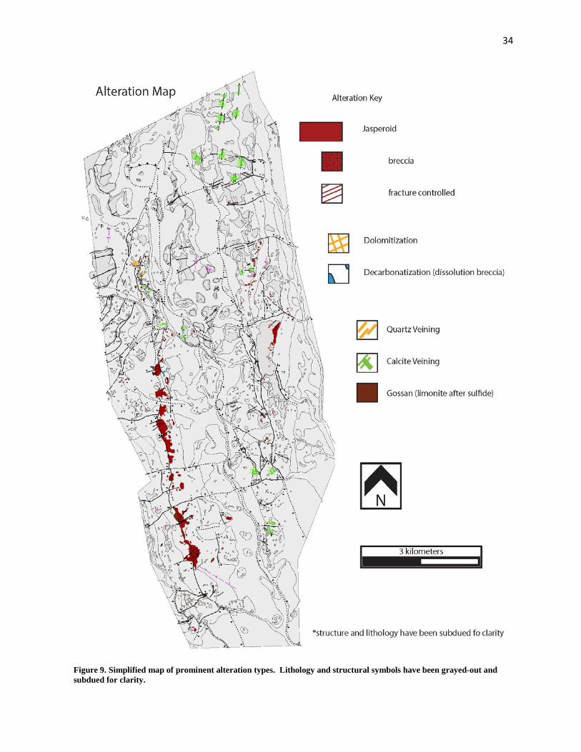
Figure 9. Simplified map of prominent alteration types. Lithology and structural symbols have been grayed-out and subdued for clarity.

35
6.2 Hydrothermal alteration and mineralization in the map area
In this project, specific categories of rock alteration were mapped including jasperoid (in
three stages of replacement: fracture-controlled, breccia, and complete replacement),
decarbonatization of carbonate host rock, dolomitization, and advanced stage argillic alteration.
The mineralization mapped was limited to limonite (incipient limonite to gossan) and sulfides
(pyrite, arsenopyrite, and marcasite), because at the scale that was mapped, this was what could
be identified (Figure 9).
The most conspicuous alteration in the map area is the jasperoid replacement bodies.
Jasperoid is highly-resistant to weathering in contrast to the easily-weathered decarbonatization.
This difference in outcrop weathering pattern generates a bias to jasperoid alteration regarding
surface maps of Carlin-type deposits. The competent nature of this replacement silica is
responsible for the high-relief topographic expression of Lookout Mountain-Ratto Ridge. Three
levels of replacement have been denoted on the map, from incipient to strong they are: fracture-
controlled, breccia, and complete replacement (Figure 9). Jasperoid can vary in physical
appearance; commonly, a single outcrop can exhibit several distinguishable features (color,
replacement texture, etc.) which may or may not be due to the protolith. Within the map area,
jasperoid range from brown, brown-gray, dark to light gray, and white. Outcrops of jasperoid are
generally highly fractured, and often exhibit multiple stages of structural brecciation. At the
hand-lens scale, jasperoid ranges in texture, from a phaneritic saccharoidal texture to aphanitic
crypto-crystalline silica. The most common jasperoid host units within the map area are the
Cambrian Eldorado dolostone, Cambrian Hamburg dolostone, and the Devonian Sentinel
Mountain/Bay State dolostones. While the jasperoid replacing the Cambrian dolostone tend to be
brown to dark-gray/brown, the jasperoid replacing the Devonian dolostone is distinctly lighter in
color, usually white to gray-white.
36
Decarbonatization accompanies most carbonate rocks in the map area. This alteration is
defined by the removal of carbonate material and manifests itself in outcrop as bulk and local
rock volume-loss, obliteration of original rock texture, and increased porosity (vugs, pock-marks,
etc.). Due to the scale of this project, decarbonatization was defined in the map area as either
present or absent. Also, a biased in the extent of decarbonatization is likely skewed due to the
lack of manifestation in outcrop. This alteration was mostly observed in road cuts and pit-walls.
The distribution of limonite was mapped by strength (incipient to strong), and abundance
(low to high). Due to the scale of the project, main limonite minerals, goethite, hematite, and
jerosite were not differentiated. Limonite was further characterized as being either: fracture-
controlled, disseminated, and/or pervasive. Where limonite was both pervasive and strong the
term ‘gossan’ was used, as these relatively competent, massive, vuggy siliceous limonitic bodies
were easily distinguishable and cropped out well (Blanchard, 1968). Sulfides were treated in a
similar manner and were mapped in the same manner as limonite. The general term ‘sulfide’ was
used in lieu of mapping specific minerals (e.g., pyrite, arsenian pyrite, marcasite, realgar, etc.), in
adherence to the scale of the project.
Argillic alteration was mapped only where feldspars or other silicates were completely
replaced by clay. Argillic-alteration was only recognized in local igneous bodies which contained
phenocrysts. Since most igneous bodies corresponded to dikes emplaced along faults and/or
fractures, the argillic alteration marked hydrothermal fluid pathways along these zones.
A zone of rather strong hydrothermal alteration and associated mineralization appears to
be centered in Rocky Canyon. It is characterized by dolomitization, milky-quartz veining,
gossanous outcrops, and black jasperoid breccia-matrix replacement (Figures 5, 8, and 10B.
Much of this mineralization and alteration appears to be different than the Carlin-type
mineralization observed along the Lookout Mountain fault to the south. Instead, with black

37
jasperoid, entrained within the milky quartz veins and the presence of dolomitization, this
alteration assemblage resembles that of polymetallic deposits found proximal to the Eureka
mining district (Geddes-Bertrand Mine, Ruby Hill Mine, etc.) (Nolan, 1962). This mineralization
could be related to the granite dike system located at depth in northern Rocky Canyon (Barton,
1987). These granite dikes have generated a skarn alteration halo that is observed at the surface
in northern Rocky Canyon and in drill-hole data. This shale has undergone contact
metamorphism to hornfels.
Along Lookout Mountain and Ratto Ridge, disseminated gold is hosted within the
Cambrian Hamburg dolostone and an overlaying sealing unit, the Cambrian Dunderberg shale.
The mineralization trends parallel with the Lookout Mountain fault trace along the ridgeline.
Alteration and mineralization are also observed to the east, in the Oswego structural trend, as well
as within the Cambrian Eldorado dolomite to the northern part of the map area.
38
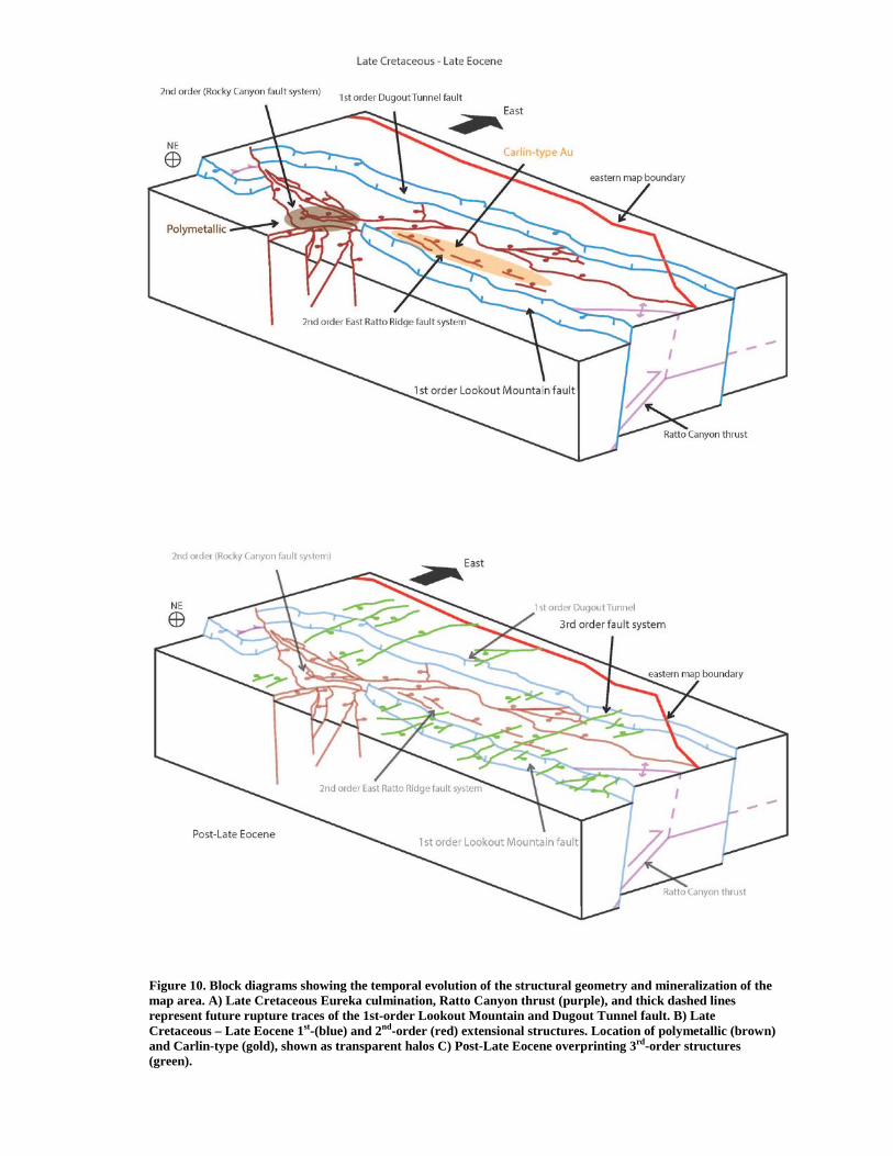
Figure 10. Block diagrams showing the temporal evolution of the structural geometry and mineralization of the map area. A) Late Cretaceous Eureka culmination, Ratto Canyon thrust (purple), and thick dashed lines represent future rupture traces of the 1st-order Lookout Mountain and Dugout Tunnel fault. B) Late Cretaceous – Late Eocene 1st-(blue) and 2nd-order (red) extensional structures. Location of polymetallic (brown) and Carlin-type (gold), shown as transparent halos C) Post-Late Eocene overprinting 3rd-order structures (green).

39
7. Discussion
7.1 Structural evolution of the map area
The Early Cretaceous construction of the Eureka culmination, a ca. 20 km-wide, 80 km-
long anticline (Long et al., 2014), generated the underpinning structural architecture, and set the
stage for the superimposed extensional regime (Figure 10A). The map area occupies the
approximate center of this regional-scale anticlinal culmination. The culmination is interpreted
by Long (2014) as a fault-bend fold, that was constructed by motion on the east-vergent blind
Ratto Canyon thrust over a Cambrian to Silurian footwall ramp at depth (Figure 10A).
After construction of the Eureka culmination, motion on 1st- and 2nd-order normal faults
took place, and is interpreted here as the result of gravitational collapse of this regional structural
high. This faulting can be bracketed between Late Cretaceous (ca. 86 Ma), the age of contact
metamorphism in northern Rocky Canyon that is cut by the Dugout Tunnel fault, and Late
Eocene (ca. 37 Ma), based on the overlapping relationship of the sub-volcanic unconformity
across 1st- and 2nd- order faults in the southern part of the map area (Long et al., 2014). The 1st-
order (km-scale offset), large-throw, down-to-the-west Lookout Mountain and Dugout Tunnel
faults formed during this event (Figures 7; 10B). Because of a similar strike, steep west-dipping
geometry, and amount of throw, the Lookout Mountain fault is interpreted here to be of similar
age and origin as the Dugout Tunnel fault. Throughout much of the map area, these two
structures strike parallel to one another. The Dugout Tunnel fault maintains an average ~3 km
offset throughout the map area until the change in strike to the north. The Lookout Mountain
fault maintains both a north strike and ~2.5 km offset through the southern half of the map area,
only to abruptly decrease in offset north of Lookout Mountain. Here, this offset is distributed
among structures of the 2nd-order Rocky Canyon fault system (Plate 1; Figures 7, 8, 10B), that
propagates north into Rocky Canyon. This complex fault system is difficult to trace in northern

40
Rocky Canyon, but at least one fault is interpreted to offset the Dugout Tunnel fault at the north
end of the map area. The Lookout Mountain fault, Dugout Tunnel fault, and Rocky Canyon fault
system are interpreted here to be similar in age. This complex array of smaller-scale structures
defines an accommodation zone that transfers displacement between the Lookout Mountain and
Dugout Tunnel faults (a synthetically-breached relay-ramp, e.g., Faulds and Varga, 1998) (Figure
13) (see section 7.2 below).
An additional set of east-dipping, 2nd-order faults is present within the footwall of the
Lookout Mountain fault, defined above as the East Ratto Ridge fault set (Figures 6 and 10B).
These antithetic, sub-parallel, decameter-scale offset normal faults are observed only in drill-
holes. This fault set is characterized by their steep (~60° ± 10°) eastward dip, and their spatial
relationships with the highly-thinned Cambrian Hamburg dolomite that underwent significant
decarbonatization (Figure 7D-E). Although the age of these faults relative to the age of Carlin-
type mineralization remains enigmatic, overlap of Tertiary volcanics provide evidence for their
youngest possible age (Late Eocene). Due to their amount of offset (100’s of meters) and
geometric characteristics, it is interpreted that these faults are genetically coincident with the 1st -
and 2nd -order fault systems.
Finally, a 3rd- order system of east-northeast striking, small-offset (meter- to sub-meter scale)
dominantly dip-slip normal faults dissect the map area, offsetting the 1st- and 2nd -order
extensional structures (Figure 6, 10C). These faults are generally south-dipping, with only a few
dipping to the north. The geometry and amount of offset of these faults were mapped on the
jasperoid ridges along the Lookout Mountain and Dugout Tunnel faults, as well as in the Eureka
quartzite. Offsets of jasperoid bodies provide an earliest time of fault movement, which is post-
Late Eocene.

41
7.2. Mineralization: spatial patterns and structural controls
Polymetallic alteration and mineralization is evident within uplifted fault-blocks in the
2nd -order Rocky Canyon fault system and is differentiated from Carlin-type alteration by the
defining characteristics mentioned above (section 6.2). This mineralization is interpreted to be
Late Cretaceous (ca. 86 Ma) in age, because of its spatial association with granite dikes and
associated contact metamorphism in northern Rocky Canyon. Therefore, the polymetallic
alteration/mineralization is interpreted to pre-date extension, and to have been exhumed as a
result of younger motion on the 2nd-order Rocky Canyon fault system.
The timing of mineralization along the Lookout Mountain fault is interpreted to be Late
Eocene, synchronous with dated intrusive rocks in the mineralized Lookout Mountain pit (Long
et al., in review) (Plate 1). In addition, based on the stratigraphic level of the Late Eocene
unconformity across the Lookout Mountain, Dugout Tunnel, Oswego fault, and East Ratto Ridge
fault set, and the presence of rhyolitic dikes of presumable Late Eocene age intruding along the
Lookout Mountain fault the 1st - and 2nd -order extensional fault systems had to have been
completed by the Late Eocene, preceding the Carlin-type mineralization event.
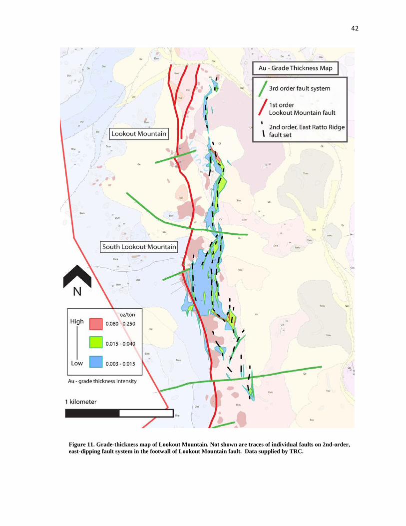
In an attempt to assess structural controls on the spatial patterns of mineralization, a gold-
thickness map was constructed (Figure 11). Gold grade-thickness maps are a tool that illustrates
the two-dimensional, horizontal spatial representation of Au mineralization intensity. An Au
grade-thickness map of the Carlin-type ore-body in the southern half of the map area was drafted
(Figure 11), and was generated from data obtained in exploration drilling along Lookout
Mountain and South Lookout Mountain by TRC. Since this map is only a two-dimensional
representation, and projects concentration data to the location of the drill-hole collar at the
surface, even in non-vertical drill-holes, relationships between depth, consistency, and
concentration can be difficult to discern. However, educated interpretations can be drawn if the
42
Figure 11. Grade-thickness map of Lookout Mountain. Not shown are traces of individual faults on 2nd-order, east-dipping fault system in the footwall of Lookout Mountain fault. Data supplied by TRC.

43
following assumptions are made: 1) we have access to total depth of drill-holes, 2) holes are
drilled through the zone of mineralization; and 3) the distribution of mineralization can be
attributed to an ore-deposit type. Additionally, utilizing TRC’s cross-sections drawn
perpendicular to the mineralized trend (e.g., Figure 12), the geometry of the ore-body at depth can
be illustrated, to provide support to the 2-D patterns illustrated on the gold-thickness.
Figure 12. Annotated cross-section, drafted by Timberline Resources Corporation, showing the geometry of Au mineralization at depth, and illustrating the system of 2nd- order antithetic faults in the footwall of the LMF.

44
In the map area, zones of elevated grade thickness run sub-parallel to the strike of the
Lookout Mountain fault, with the majority of the zones confined to the footwall (Figure 13). The
zones of moderate grade thickness have a distinct linear geometry, which trends sub-parallel to
parallel to the Lookout Mountain fault. This pattern outlines the map pattern of the East Ratto
Ridge fault set, an antithetic, 2nd -order fault system within the altered ground sub-surface. The
existence of these faults is supported in drill-hole data (Figure 12). The close proximity from
Figure 13. Schematic breached (faulted) relay ramp accommodation zone. Green arrow points to relay ramp between two 1st-order, synthetic normal faults. Modified from Faulds and Varga (1998).
Figure 14. Schematic diagram of a wall-damage zone of a master fault (blue) exhibiting opposing dips of antithetic faults (red). Modified from Micklethwaite (2010).

45
one fault to another allowed for increased permeability due to interconnected network of damage
zones (Caine et al., 1996). These 2nd-order faults are interpreted to have been integral for creating
zones of localized fluid flow and thus, were favorable sites for mineralization. The majority of
the mineralization related to the 1st -order Lookout Mountain fault are spatially coincident with,
and were strongly controlled by, this 2nd -order antithetic fault system.
7.3 Testing predictions of mineralization in accommodation zones
An accommodation zone is defined as an area of faulting and/or folding that serves to
transfers slip between larger structures (Faulds and Varga, 1998). These zones manifest
themselves as belts of overlapping fault terminations and can separate systems of either synthetic
faults or antithetic faults (Faulds and Varga, 1998). The majority of the map area occupies such
an accommodation zone (Figure 7 and 10B); the 1st -order Lookout Mountain fault and Dugout
Tunnel are interpreted to be genetically linked, and due to style of deformation, respective
geometries, and spatial distribution of offset, the 2nd –order Rocky Canyon fault system is
interpreted to represent an accommodation zone that connects them (Figure 13). Specifically, this
accommodation zone represents a synthetically-breached relay ramp, using the terminology of
Faulds and Varga (1998).
Wall-damage and linking-damage zone structures are proposed to control the migration
of fluids and influence the localization of gold mineralization within accommodation zones
(Figure 14) (Micklethwaite, 2011). A damage zone is defined as the volume of deformed wall
rocks around a fault surface that results from the propagation, initiation, and the build-up of slip
along faults. Damage zones are classified into different geometric types depending on their
location relative to the master faults in an accommodation zone (Kim et al., 2004). Tip-damage

46
zones are developed at the tips of faults, linking-damage zones form where adjacent fault
segments interact and link (e.g., stepovers), and wall-damage zones represent faulting and
fracturing in the proximal wall-rock region of a fault. TRC’s drilling campaign has revealed
closely-spaced concentrations of hydrothermal dissolution of carbonate, accompanying
silicification, and the formation of jasperoid bodies along the large-throw Lookout Mountain fault
with gold-mineralization localized in the footwall (Figures 10B, 11, and 12). The footwall of the
1st -order Lookout Mountain fault contains a set of 2nd -order east-dipping faults (East Ratto
Ridge fault set) which are spatially coincident with this alteration and mineralization (Figure 10C,
11, and 12). It is interpreted that these 2nd -order antithetic (to the Lookout Mountain fault) faults
represent a wall-damage zone in the footwall of the 1st –order Lookout Mountain fault, and thus
are responsible for the requisite ground preparation for the formation of the Carlin-type ore-
deposit.
8 Conclusions
1. The Early Cretaceous construction of the Eureka culmination generated the
underpinning structural architecture for subsequent gravitational collapse which was manifested
by the 1st- and 2nd order extensional fault systems, which are post ca. 86 Ma (age of granite dikes
and contact aureole), and pre-Late Eocene. The 2nd- and 1st-order faults are interpreted to be
genetically related, defining a zone of accommodation of 2nd-order faults that transfer
displacement between two synthetic 1st-order structures (i.e., a synthetically breached relay-ramp,
e.g., Faulds and Varga, 1998). Finally, a 3rd -order fault set cross-cuts all earlier structures, and is
presumably post-late Eocene.

47
2. Polymetallic alteration in northern Rocky Canyon is interpreted to be associated with
Late Cretaceous granite dike system at depth. Rocks that underwent polymetallic alteration and
mineralization were later exhumed by structures of the Rocky Canyon fault system.
3. The timing of Carlin-type mineralization along the Lookout Mountain fault is
interpreted to be Late Eocene, synchronous with intrusive rocks in the mineralized Lookout
Mountain pit. The majority of the mineralization related to the 1st -order Lookout Mountain fault
is actually off-fault, and is spatially coincident with the 2nd-order, antithetic East Ratto Ridge fault
system. This fault system is interpreted as the primary structural control for localizing fluid flow
and formation of the Carlin-type ore body.
4. Wall-damage zone structures are proposed control the migration of fluids and
influence the localization of gold mineralization in accommodation zones. The 2nd-order East
Ratto Ridge fault system, which is antithetic to and in the immediate footwall of the 1st-order
Lookout Mountain fault, is interpreted to represent a footwall wall-damage zone. Therefore,
mineralization patterns in the south Eureka district confirm predictions for structural controls on
mineralization in accommodation zones.
48
References Cited
Arehart, G., and Chakurian, A., 2003, Evaluation of radioisotope dating of Carlin-type deposits in
the Great Basin, western North America, and implications for deposit genesis: Economic
Geology, v. 98, p. 235–248.
Armstrong, R.L., 1968, Sevier orogenic belt in Nevada and Utah: Geological Society of America
Bulletin, v. 79, p. 429-458.3.
Bakken B.M., 1990, Gold mineralization, wall-rock alteration and the geochemical evolution of
the hydrothermal system in the main ore body, Carlin Mine, Nevada: Unpublished Ph.D. thesis,
Stanford, CA, Stanford University, 236 p.
Best, M.G., Barr, D.L., Christiansen, E.H., Gromme, S., Deino, A.L., and Tingey, D.G., 2009,
The Great Basin Altiplano during the middle Cenozoic ignimbrite flareup: insights from volcanic
rocks: International Geology Review, v. 51, p. 589-633.
Brimhall, G. H, Dilles, John, Proffett, J., 2006, The Role of Geological Mapping in Mineral
Exploration in Wealth Creation in the Minerals Industry, Special Publication 12, Anniversary
Publications of the Society of Economic Geologists, p. 221-241
Blanchard, R., 1968. Interpretation of leached outcrops. Nevada Bureau of Mines and Geolgy.
Bulletin 66 (196 pp).
Caine, J., Evans, J., and Forster, C., 1996, Fault zone architecture and permeability structure:
Geology, p. 1025–1028.
49
Cline, J.S., Hofstra, A.H., Muntean, J., Tosdal, R.M., and Hickey, K.A., 2005, Carlin-type gold
deposits in Nevada: critical geologic characteristics and viable models: Society of Economic
Geologists Abstracts with Programs, 100th anniversary volume, p. 451-484.
Cook, H.E., and Corboy, J.E., 2004, Great Basin Paleozoic carbonate platform: facies, facies
transitions, depositional models, platform architecture, sequence stratigraphy, and predictive
mineral host models: U.S.G.S. Open-File Report 2004-1078, 129 p.
Cox, D., and Singer, D., 1986, Mineral deposit models: U.S. Geological Survey, Bulletin 1693
Dahlstrom, C.D.A., 1969, Balanced cross sections: Canadian Journal of Earth Sciences, v. 6, p.
743–757, doi: 10.1139/e69-069.
DeCelles, P.G., and Coogan, J.C., 2006, Regional structure and kinematic history of the Sevier
fold-and-thrust belt, central Utah: Geological Society of America Bulletin, v. 118, p. 841-864.
Dickinson, W.R., 2002, The Basin and Range Province as a composite extensional domain:
International Geology Review, v. 44, p. 1–38.
Dilles, P.A., Wright, W.A., Monteleone, S.E., Russell, K.D., Marlowe, K.E.,Wood, R.A., and
Margolis, J., 1996, The geology of the West Archimedes deposit: A new gold discovery in the
Eureka mining district, Eureka County, Nevada, in Coyner, A.R., and Fahey, P.L., eds., Geology
and Ore Deposits of the American Cordillera: Symposium Proceedings: Reno, Geological Society
of Nevada, p. 159–171.
Emsbo P., and Hofstra, A.H., 2003, Origin and significance of post dissolution collapse breccias
cemented with calcite and barite at the Meikle gold deposit, northern Carlin trend, Nevada:
ECONOMIC GEOLOGY, v. 98, p. 1243–1252.

50
Faulds, J. E., and Varga, R. J., 1998, The role of accommodation zones and transfer zones in the
regional segmentation of extended terranes, in Faulds, J. E., and Stewart, J. H., eds.,
Accommodation zones and transfer zones: Regional segmentation of the Basin and Range
province: Geological Society of America Special Paper 323, p. 1–45.
Faulds, J., and Hinz, N., 2011, Assessment of favorable structural settings of geothermal systems
in the Great Basin, Western USA: Geothermal …, v. 35.
Henry, C.D., 2008, Ash-flow tuffs and paleovalleys in northeastern Nevada: Implications for
Eocene paleogeography and extension in the Sevier hinterland, northern Great Basin: Geosphere,
v. 4, p. 1, doi: 10.1130/GES00122.1.
Hofstra, A.H., and Cline, J.S., 2000, Characteristics and models for Carlin-type gold deposits, in,
Thompson, T.B., ed., Society of Economic Geology Reviews, v. 13, Denver, CO, p. 163-220.
Ketner, K.B., Murchey, B.L., Stamm, R.G., Wardlaw, B.R., 1993. Paleozoic and Mesozoic rocks
of Mount Icabod and Dorsey Canyon, Elko County, Nevada—evidence for Post-early Triassic
emplacement of the Roberts Mountains and Golconda allochthons. U.S. Geological Survey
Bulletin 1988, 12.
Kim, Y.-S., Peacock, D.C.., and Sanderson, D.J., 2004, Fault damage zones: Journal of Structural
Geology, v. 26, p. 503–517, doi: 10.1016/j.jsg.2003.08.002.
Long, S.P., Henry, C.D., Muntean, J.H., Edmondo, G.P., and Thomas, R.D., 2012, Preliminary
geologic map of the southern Eureka mining district, Eureka and White Pine Counties, Nevada:
Nevada Bureau of Mines and Geology Open-File Report 12-6, 1:24,000-scale, 2 plates.
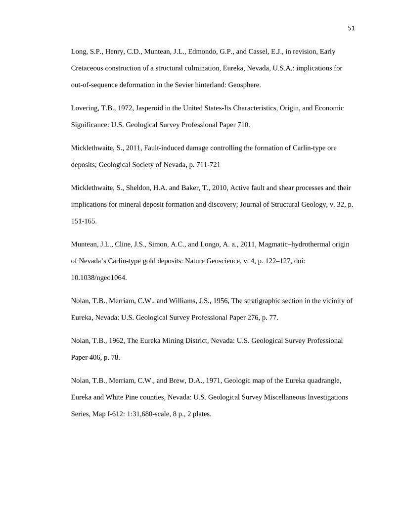
51
Long, S.P., Henry, C.D., Muntean, J.L., Edmondo, G.P., and Cassel, E.J., in revision, Early
Cretaceous construction of a structural culmination, Eureka, Nevada, U.S.A.: implications for
out-of-sequence deformation in the Sevier hinterland: Geosphere.
Lovering, T.B., 1972, Jasperoid in the United States-Its Characteristics, Origin, and Economic
Significance: U.S. Geological Survey Professional Paper 710.
Micklethwaite, S., 2011, Fault-induced damage controlling the formation of Carlin-type ore
deposits; Geological Society of Nevada, p. 711-721
Micklethwaite, S., Sheldon, H.A. and Baker, T., 2010, Active fault and shear processes and their
implications for mineral deposit formation and discovery; Journal of Structural Geology, v. 32, p.
151-165.
Muntean, J.L., Cline, J.S., Simon, A.C., and Longo, A. a., 2011, Magmatic–hydrothermal origin
of Nevada’s Carlin-type gold deposits: Nature Geoscience, v. 4, p. 122–127, doi:
10.1038/ngeo1064.
Nolan, T.B., Merriam, C.W., and Williams, J.S., 1956, The stratigraphic section in the vicinity of
Eureka, Nevada: U.S. Geological Survey Professional Paper 276, p. 77.
Nolan, T.B., 1962, The Eureka Mining District, Nevada: U.S. Geological Survey Professional
Paper 406, p. 78.
Nolan, T.B., Merriam, C.W., and Brew, D.A., 1971, Geologic map of the Eureka quadrangle,
Eureka and White Pine counties, Nevada: U.S. Geological Survey Miscellaneous Investigations
Series, Map I-612: 1:31,680-scale, 8 p., 2 plates.

52
Nolan, T.B., Merriam, C.W., and Blake, M.C., Jr., 1974, Geologic map of the Pinto Summit
quadrangle, Eureka and White Pine counties, Nevada: U.S. Geological Survey Miscellaneous
Investigations Series, Map I-793: 1:31,680-scale, 14 p., 2 plates.
Oldow, J.S., 1984, Evolution of a late Mesozoic back-arc fold and thrust belt, northwestern Great
Basin, U.S.A.: Tectonophysics, v. 102, p. 245–274, doi: 10.1016/0040-1951(84)90016-7.
Papke, K.G., 1984, Barite in Nevada: Nevada Bureau of Mines and Geology
Bulletin 98, 125 p.
Peters, S.G., 2004, Syn-deformational features of Carlin-type Au deposits: Journal of Structural
Geology, v.26, p.1007-1023.
Roberts, R.J., Hotz, P.E., Gilluly, J., Ferguson, H.G., 1958. Paleozoic rocks of north-central
Nevada. American Association of Petroleum Geologists Bulletin 42 (12), 2813–2857.
Silberling, N.J., 1975. Age relationships of the Golconda thrust fault, Sonoma Range, north-
central Nevada: Geological Society of America Special Paper 163, 28.
Speed, R. C., and Sleep, N. H., 1982, Antler orogeny and foreland basin: A model: Geological
Society of America Bulletin, v. 93, p. 815-828
Steininger, R. C., Klessig, P. J., and Young, T. H., 1987, Geology of the Ratto Canyon gold
deposits, Eureka County, Nevada, in Johnson, J. I., (ed.), Bulk Mineable Precious Metal Deposits
of the Western United States, Guidebook for Field Trips, p. 293-304.
Suppe, J., 1983, Geometry and kinematics of fault-bend folding: American Journal of Science, v.
283, p. 684–721, doi:10.2475/ajs.283.7.684.
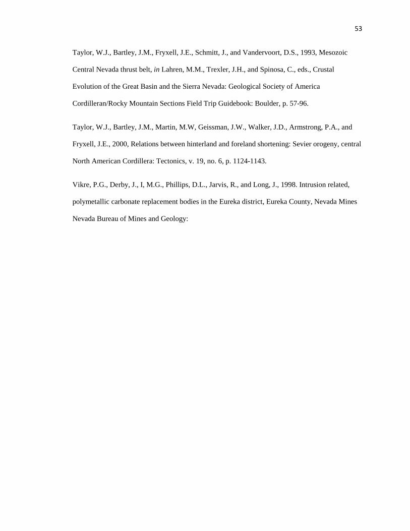
53
Taylor, W.J., Bartley, J.M., Fryxell, J.E., Schmitt, J., and Vandervoort, D.S., 1993, Mesozoic
Central Nevada thrust belt, in Lahren, M.M., Trexler, J.H., and Spinosa, C., eds., Crustal
Evolution of the Great Basin and the Sierra Nevada: Geological Society of America
Cordilleran/Rocky Mountain Sections Field Trip Guidebook: Boulder, p. 57-96.
Taylor, W.J., Bartley, J.M., Martin, M.W, Geissman, J.W., Walker, J.D., Armstrong, P.A., and
Fryxell, J.E., 2000, Relations between hinterland and foreland shortening: Sevier orogeny, central
North American Cordillera: Tectonics, v. 19, no. 6, p. 1124-1143.
Vikre, P.G., Derby, J., I, M.G., Phillips, D.L., Jarvis, R., and Long, J., 1998. Intrusion related,
polymetallic carbonate replacement bodies in the Eureka district, Eureka County, Nevada Mines
Nevada Bureau of Mines and Geology:

70
48
37
55
62
73
28
65
56
71
73 68
75
36
72
37
68
85
2186
18
73
6630
32
40
42
57
4068
32
57
60
62
5172
60
60 32
35
82
72
51
7225
15
60
70
67
21
50
45
33
70
5547
50
55
52
61
72
6253
2722
31
27
20
18
63
72
70
80
70
32 3255
46
21
12
05
05
12
65
37
56
23
70
76
47
33
71
72
52
41
12
1822
23
77
44
42
37
52
70
54
7859
45
26
80
2135
23
3720
47
61
65
31
54
30
54
45
67
48
72
81
33
47
83
7868
80
50
72
65
72
62
55
33
48
53
77
2717
22
34
25
47
54
75
23
53
63
36
50
29
78
65
32
24
68
42
35
57
23
80
62
68
22
65
58
33
57
5137
20
18
3327
40
27
3540
35
55
172020
1525
75
80
85 65
32
1224
35 17
15
27
75
70
70 63
3733
3227
29
38
31
23
1520
27
47 4047
4052
50
46
20
22
5552 39
35
50
50
5050
60
27
22
25
30
1622
32
4036
25
35
2032
22
22
2017
21
17
41
37
12
75 42
33
82
77
70
62
54
60
56
33 52 4070
1223
23603547
42
6772
80
20
65
5710
23
15
41
43
22
2753
767582
7375
56
54
72
4c2
71
80
31
8777
51
75
78
4237
22
2568
6560
72
50 38
30
60
63
32 27
41
67 37 31
6055
5756
42
53
10
10
30
6663
62 60
7270
63
72
52
30
28
45
75
32
41
7670
73
75
67
687072
67
6560
83
55
23
5862
30
65 80
30
20
85
50
52
4743
42
3235
27
75
2530
25
24
10
35
52
83
73
5761
72
5755
5722
52
40
55
61
8570
75
62 70
85
72
37
70
22
6245
25
25
37
25
35
28
15
20
33
27
30
18
36
31
80
78
80
15
85
70
36
56
27
10
15
17
33
25
673255
72
39
40
27
58
71
60
55
37
60
30
50
4554
50
4560
52
55
50
54
717067
82
90
62
4266
80
55
45
82
82
87
55
32
85
63
31
35
47
5062
21
10
68
87
79
10
80
71
56
82
27
41
45
75
52
47
45
60
75
67
57
85
80
80
30
40 60
8280
75
70
85
83
87
68
85
80
Css
Cs
Tss
Cd
Cd
Cd Cw
Cw
Og
Dbs
DbsDsm
Doc Dbs
Dsm
Doc
Doc
Doc
Dsm
Dsm
Dbs
TrtDsm
Dsm
Doc
Doc
Doc
DbDsr
QTaf
Qc
DbDsr
Qal
Qal
Qal
QalTrmv
Qal
Qc
Trsv
Trt
Trt
Ce
Oav
Ce
Cg
Cwb
Tss
Tss
Og
Ce
Og
Og
Og
Tss
Oe
Cwb
Og
Og
Cwb
Qc
Qc
Oav
Oe
Oe
Oav
Oav
DsmDsm
Dsm
DbsDsm
Dsm
Doc
Trd
Cd
Cw
Cw
Cd
Cd
Cd
TrtCw
Cw
CwCd
Cw
Cw
Trmv
Oav
Tj
Trmv
Trt
Trt
Onm
Og
Og
Og
Cd
Cg
Cg
Cg
Ce
Ce
Ce
Csc
Qal
Cs
Cg
Ce
Cs
Ce
Cg
Cg
Ce
Ce
Oav
Csc
Csc
Qc
Qc
Qc
Cs
QalQc Cs
Qc
Cs
Qc
Qc
QcCs
Cs
Cs
Cg
Qc
Cw
Qc
Qc
Qc
Qc
Qc
Qc
Qc
Qal
Qal
Qc
Qc
Qc
QcQc
Qc
Qc
Qc
Qal
Qc
Oe
Qc
Oav
Oe
Qc
Qc
Oav
Oav
Oav
Ce
Qc
Trd
Slm
Slm
Qc
Oe
Oe
QcOe
Qc
Qc
Cpm
Cpm
Cpm
Oav
CwOg
Cs
Qc
Oe
Oav
Cs
Ce
Cg
Ce
Ce
Trd
Oe
Ce
Cg
Ce
Ce Cs
Ce
Oe
Oe
Oe
Oe
Oe
Oav
Oe
Og
Trd
Onm
Oav
Oe
Oe
Oav
Qc
Oe
Oe
Oe
Oe
Oe
Oe
Oav
Oe
Qc
Slm
Doc
Trd
Og
Onm
Oav
DbpSlm
Slm
Dsr
Oav
Qc
Slm
Oav
Oav
Oav
Ce
Css
Ce
Cg
Ce
Ce Cg
Css
Cg
Css
Qc
Qc
Cg
Qc
Qc
Css
Ch
Csc
Cg
Ce
Ce
Qc
Qc
Slm
Qc
Oe
Oe
Qc
Css
Oe
Cp
Qc
Oav
Tss
Tj
Tj
Cs
Qal
Qal
Qc
Qc
Db
Dsr
Dsm
Slm
DsrOg
Qc
Qal
Qal
Qal
Dsm
Trd
DsmDbp
Db
Trd
Cw
Csc
Ch
Qf
Qc
Cd
Doc
Ch
Qal
Qal
Qal
Trmv
Trmv
Trmv
Qc
Oav
Qc
Cd
Qc
Qc
Qc
Cg
Qc
Qc
Qc
Trt
Trt
Csc
Oav
Tss
Tss
Qal
Oe
Oe
Oe
Og
Og
Trd
Oav
Oav
Qal
Qal
Trsv Qc
Cd
Qc
Qc
Qc
Qc
Qc
Oe
Qal
Dbs
Qc
Oav
Qc
Qc
Dsm
Doc
Oe
Qc
Ohc
Trd
Dsm
Slm
Qf
Qc
Qc
Qc
Qc
Csc
Csc
Css
Cg
Qc
Qc
Dsm
Qc
Qal
Qc
QTaf
QTaf
QTaf
QTaf
QTaf
Qc
Qc
Oav
Oav
Trsv
Trsv
Oav
Dsm
Slm
Qal
Trd
GNMN
UTN GRID AND 1990 MAGNETIC NORTH
DECLINATION AT CENTER OF MAP AREA
0˚ 40’ 15˚ 00’
1 2 3 4
5 6 7 8
9 10 11 12
1 Hay Ranch2 Devon Peak3 Eureka4 Diamond Peak5 Combs Peak6 Spring Valley Summit7 Pinto Summit8 Silverado Mountain9 West of Bellvue Peak10 Bellvue Peak11 Pinto Summit SW12 Black Point
Adjoining 7.5’Quadrangles Names
Correlation of Map Units
Dsm
Dbs
Doc
Cp
Cg
Ce
Cpm
Css
Csc
Ch
Cd
Cwb
Cwc
Og
Onm
Oav
Oe
Ohc
Slm
Dbp
Dsr
Dmb
Trsv
Trmv
TrdTss Trt
TjbTcb
Cpm - Prospect Mountain quartzite
Cp - Pioche shale
Ce - Eldorado Dolomite
Cg - Geddes limestone
Css - Lower shale member
Csc - Clarks Spring memberCs - Secret Canyon shale
Ch - Hamburg dolomite
Cd - Dunderberg shale member
Cwc – Catlin member
Cwb – Bullwhacker memberCw - Windfall Formation
Og - Goodwin limestone
Onm - Ninemile Formation
Oav: Antelope Valley FormationOp - Pogonip Group Oe - Eureka quartzite
Ohc - Hanson Creek Formation
Dbp - Beacon Peak dolomite Db - Bartine (member of the McColley Canyon Formation)
Dsr - Sadler Ranch memberDoc - Oxyoke Canyon sandstone member
Dsm - Sentinel Mountain dolostone member
Dbs - Bay State dolostone member
Dn - Nevada Formation
Qf – arti�cial �ll
Qal - alluvium
Qc - colluvium
QTaf – alluvial fan
Tcb - collapse breccia
Tjb - jasperoid
Trmv – Richmond Mountain dacite and andesite
Tpr - Pinto Peak rhyolite
Tss – Sierra Springs Tu� Member
Trt - Pinto Basin Tu� MemberTrd – rhyolite dike
Trsv - Ratto Springs Rhyodacite
Slm - Lone Mountain dolomite
Qal Qc
QTaf
Qf
Alteration
Non Dn - Nevada Formation
Cam
bria
nO
rdov
icia
nSi
luria
nD
evon
ian
Tert
iary
Qua
tern
ary
Geologic Map of the Lookout Mountain and Oswego Structural Trends,South Eureka Mining District
Map Location
Map Symbology
A A’
B B’
C C’
D D’
E E’
Contact: Solid where certain and location accurate, long-dashedwhere approximate, short-dashed where inferred, dotted where concealed.
Normal fault Showing dip of fault and trend of striae on the fault surface (arrow);ball on downthrown side; solid where certain and location accurate, long-dashedwhere approximate, dotted where concealed, queried if identityor existence uncertain.
Syncline Solid where certainand location accurate, long-dashed where approximate.
Detachment fault Solid where certain and location accurate, long-dashed where approximate;pegs on the footwall.
30
Thrust fault Solid where certainand location accurate, long-dashed where apporximate;teeth on the footwall.
A A’
Line of cross-section
Scale 1:10,000
1 kilometer0.5
1 mile0.5
Strike and dip of bedding
o41
vInclined Vertical
¦33 ¨Strike and dip of breccia foliation
Inclined Vertical
Outline of Lookout Mountain pit
Interpreted extent of stratigraphic unit
Outcrop
Russell V. Di Fiori, Sean P. Long, John L. Muntean, and Gary Edmondo2014
Strike and dip of joints
Inclined Vertical41
54
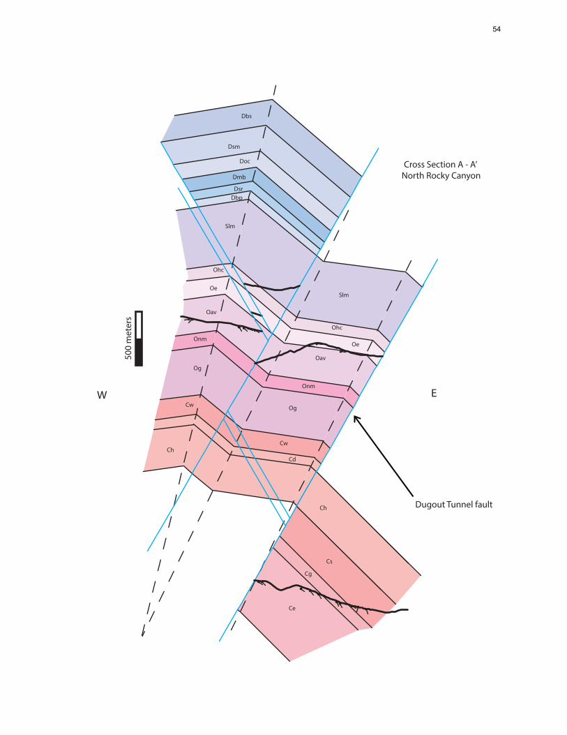
Dbs
Slm
Ohc
Oe
Oav
Og
Onm
Cw
Cd
Ch
Dbp
Dmb
Dsr
Doc
Dsm
Cs
Cg
Ce
Slm
Og
Oe
Oav
Ohc
Onm
Cw
Ch
W E
Dugout Tunnel fault
500
met
ers
Cross Section A - A’ North Rocky Canyon
54

Cross Section A - A’ North Rocky Canyon
500
met
ers
Dugout Tunnel fault
W
EBR-
69-9
6
EBR-
33-9
5
EBR-
23-9
4
EBR-
49-9
5
EBR-
41C-
95
NWT-
609C
Slm Ohc
Oe
Oav
Og
Onm
Cw
Cd
Ch
Dbp
Dmb
Dsr
Doc
Dsm
Dbs
Cs
Cg
Ce
Slm
Og
Oe
Oav
Ohc
Onm
CwCd
Ch
Cd Ohc
E
stratigraphic contact
fault Ratto Canyon thrust
apparent dip of strata
modern erosion sruface
drill-hole
54

Ohc
Slm
Dbp
Doc
Dsr
Dmb
Doc
Oe
Dbs
Dsm
Doc
Dbs
Dsm
Dsr
Slm
Cs
Ce
Ce
Cg
Oav
Cg
Cs
Ch
Oav
Onm
Og
Dbp
Dsr
Dmb
Cw
Cd
Oe
W E
400
met
ers
Cross Section B - B’ South Rocky Canyon
54

Cross Section B - B’ South Rocky Canyon
Cs
Ohc
Slm
Dbp
Doc
Dsr
DmbSlm
Ohc
Oav
Dbp
Doc
Dsr
Dbs
Dsm
Doc
Dbs
Dsm
Dsr
Dbp
Slm
Ce
Slm Cs
CeCe
Cg
Ohc
OhcOav
Onm
Og
Cg
Cg
Cs
Cs
Ch
ChCh
Onm
Og
Oav
Onm
Og
Dbp
Dsr
EBR-95-97
EBR-80-97
EBR-
58-9
6
Ch
Cw
Cd
W E
400
met
ers
Oe
Oe
54
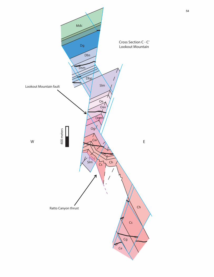
Lookout Mountain fault
Ratto Canyon thrust
Slm
Dsm
Dg
Cw
Oav
Onm
Oe
CsCh
Og
Cg
Dbp
Mdc
Slm
Dbs
Ce
Ch
Cs
Cross Section C - C’Lookout Mountain
400
met
ers
W E
54

W
E
Cross Section C - C’Lookout Mountain
Mdc
Mj
Cw
Ch
Og
Dsm
Dg
Dbs
Dsm
Doc
Doc
Doc
Dsr
Dmb
Slm
Dbp
Dsr
Dmb
Slm
Cd
Cw Oav
Onm
Oe
Ohc
Slm
Og
Cs
Cs
Cs
Cs
Ch
Ch
Cg
Cg
Og
Cg
Ce
Dsr
DbpSlm
Ch
Cd
Og
Slm
Onm
MDp
Mj
Mdc
Slm
Dbs
Cs400
met
ers
Ratto Canyon thrust
Dbp
*Ch thins to the east, as it approaches on the Lookout Moutnain fault, due to volume loss due to dissolution
Dugout Tunnel fault
Ohc
BHSE-081BHSE-030
BR-10
BHSE-029C
54
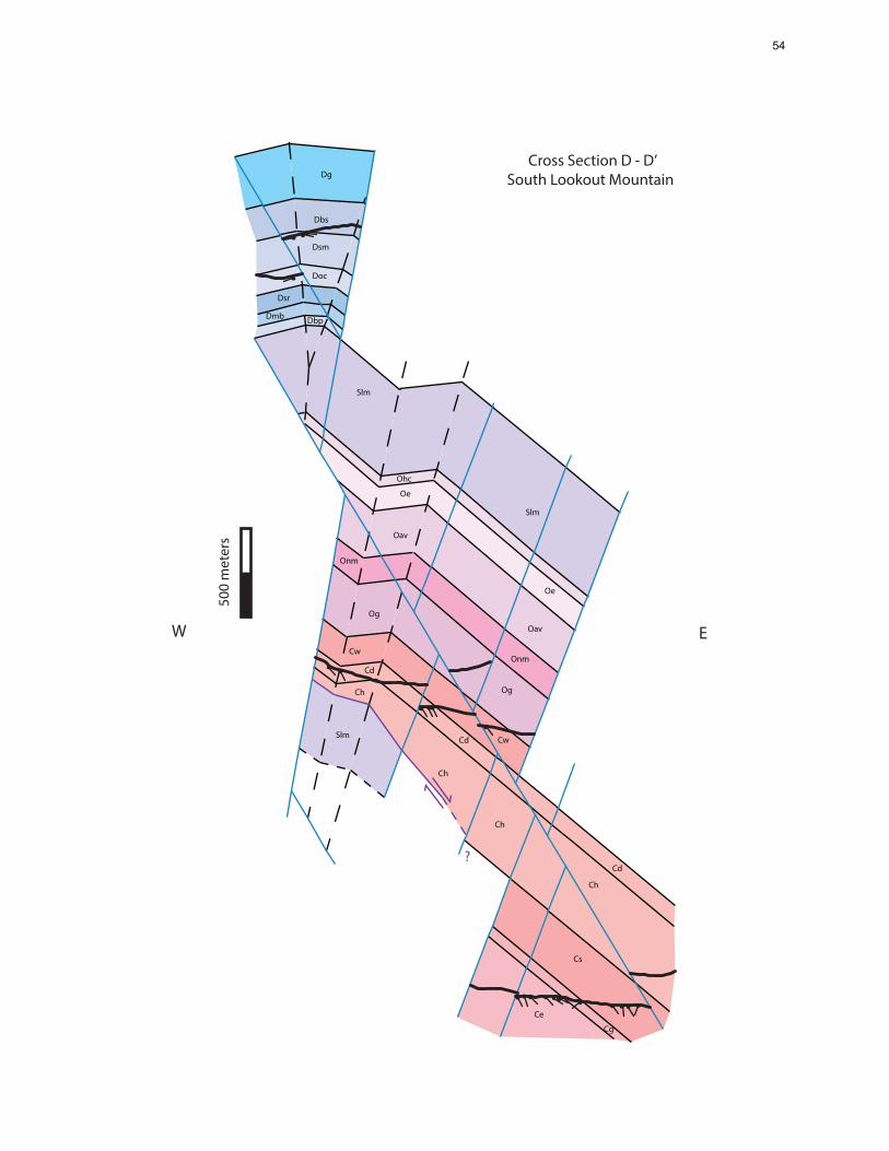
W E
Cd
Cw
Onm
Og
Slm
Ch
Cd
Ch
Cs
Ch
Cg
Ce
Cd
Ch
Oav
Oe
Ohc
Slm
Dsr
Dmb Dbp
Dsm
Dbs
Dg
Doc
Slm
Oe
Oav
Onm
Og
Cw
?
Cross Section D - D’South Lookout Mountain
500
met
ers
54
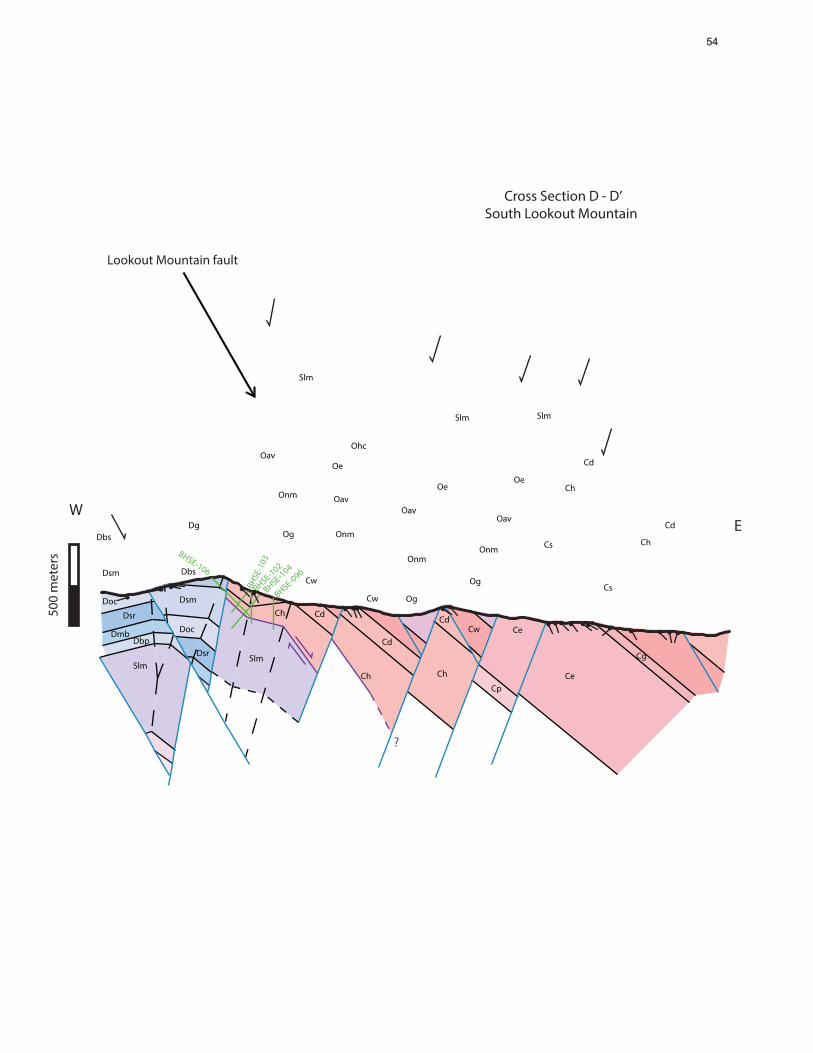
Cross Section D - D’South Lookout Mountain
Dbs
Dsm
Dsm
Dbs
Doc
Dg
Cw
Cd
Oav
Onm
OeOav
Onm
Og
Ohc
Slm
Og
Onm
Oe
Oav
Oe
Oav
Onm
Og
Cw
Cd
Ch
Cs
Cg
Cd
Cw
Cd
Ch
Ce
Cp
Cd
Ch
Cs
Ce
Doc
Dsr
Dsr
DmbDbp
Slm
SlmSlm
Slm
Ch
BHSE-106
BHSE
-103
BHSE-102
BHSE-104
BHSE-096
Ch500
met
ers
WE
?
Lookout Mountain fault
54
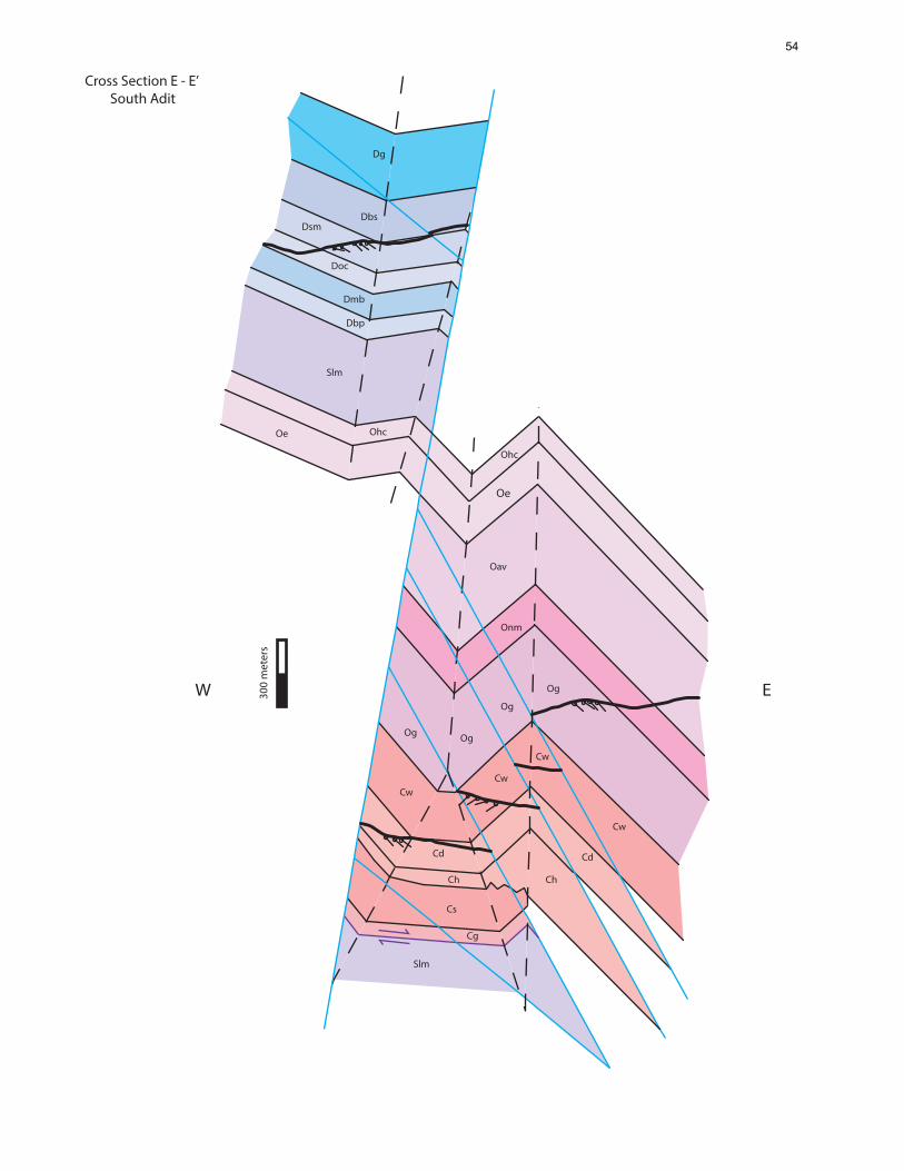
W E
Slm
Cs
Ch
Og
Cw
Dmb
Dbp
Doc
DsmDbs
Slm
Ohc
Dg
Cg
Ch
Og
Cw
Cd
Og
Cw
Oav
Onm
Cw
Og
Ohc
Cd
Cross Section E - E’ South Adit
Oe
Oe
54

WE
*Tertiary and Quaternary rock units omitted for simplicity
EBR-18-94
BR-1
3
BR-7
7
RTR-
206
BHSE
-007
300
met
ers
Cross Section E - E’ South Adit
Cg
Lookout Mountain fault
Oe
54