fokker e.i eindecker - zenoah zg · pdf file16 nails wing draw ing building board 200 x 50 cm...
TRANSCRIPT
Fokker E.I Eindecker
1 / 2 , 5 ( 4 0 % ) s c a l e R C
P H O T O M A N U A L

2
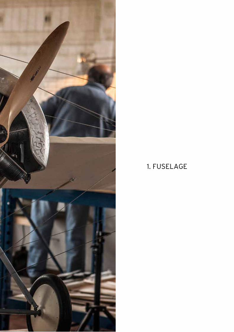
1. FUSELAGE

4
A
B
C
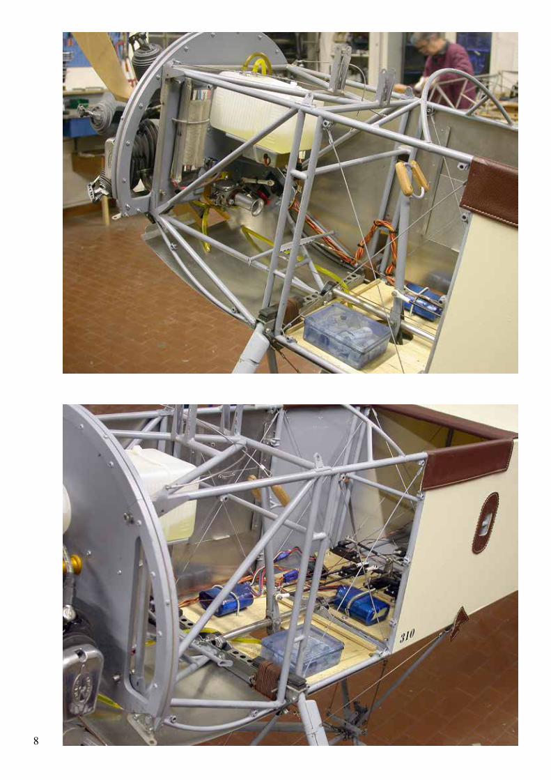
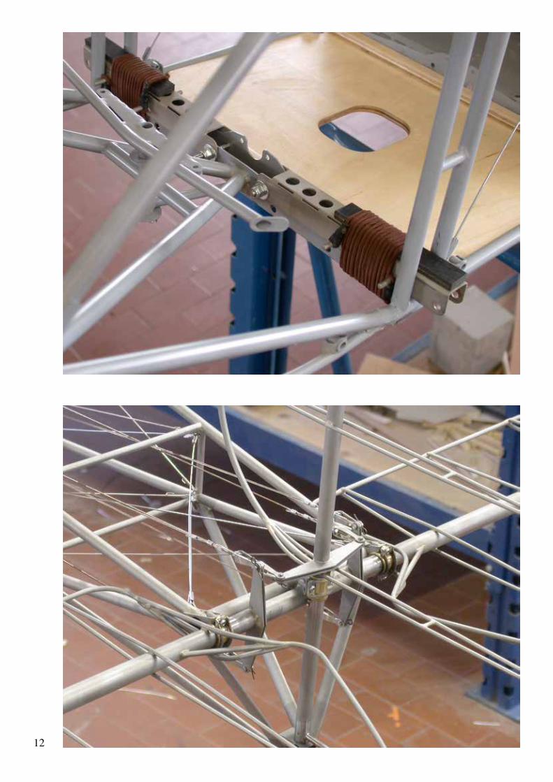
The fuselage is reinforced the same as on the full-size with internal wire bracing. No turnbuckles are needed. Install the wires as shown in the drawings and photos.Important: to prevent distortion of the fuselage do not over tighten the wires!A slight tension is sufficient, the fuselage is not a guitar... After a few attempts you will find the right tension. Slightly loose wires have no negative effect on the strength of the fuselage.
5
D
E
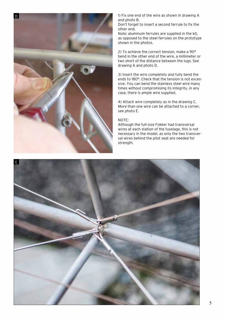
1) Fix one end of the wire as shown in drawing A and photo B.Don’t forget to insert a second ferrule to fix the other end.Note: aluminum ferrules are supplied in the kit, as opposed to the steel ferrules on the prototype shown in the photos.
2) To achieve the correct tension, make a 90° bend in the other end of the wire, a millimeter or two short of the distance between the lugs. See drawing A and photo D.
3) Insert the wire completely and fully bend the ends to 180°. Check that the tension is not exces-sive. You can bend the stainless steel wire many times without compromising its integrity, in any case, there is ample wire supplied.
4) Attach wire completely as in the drawing C. More than one wire can be attached to a corner, see photo E.
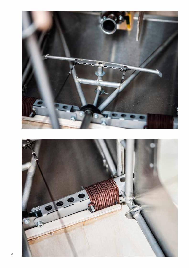
NOTE:Although the full-size Fokker had transversal wires at each station of the fuselage, this is not necessary in the model, as only the two transver-sal wires behind the pilot seat are needed for strength.
6
7
8
9

10
11
12

13

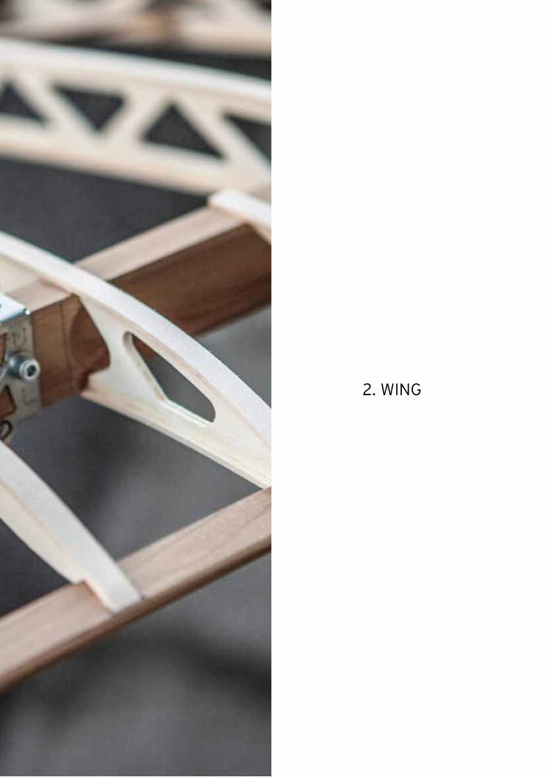
2. WING

16
N A I L S
W I N G D R A W I N GB U I L D I N G B O A R D 2 0 0 x 5 0 c m a p p r o x .
8 M M P O P L A R P L Y W O O D R I B S U P P O R T
1) Place the wing drawing on a flat building board of approx. 200 x 50 cm.
2) Protect the drawing with a transparent sheet.
3) Nail the rib support on the drawing to build the wing jig as shown in drawing A and B.
4) Protect each rib support with sellotape.
5) Fix the flexible plywood wing tip jig on the rib supports, use some self-tapping screws.
6) Protect the border of the wing tip jig with sellotape.
7) Build the wing tips by laminating 6 cedar strips as shown in photo C.
A
B

17
C

18
2 , 5 m m H O L E
I N N E R S T E E L F I T T I N G O N S P A R R O O T W I T H L U G F O R I N T E R N A L B R A C I N G W I R E
O U T E R S T E E L F I T T I N G O N S P A R R O O T
8) Mount the steel fittings on both sides of the spars (photo E) and remove the wood following the shape of the fittings as in the drawing D.
9) Drill a 2.5 mm hole on the spar as in the drawing D.
10) Mount the wire attachments as in the drawings F and G.
11) Place a lime wood strip on each rib support and glue the trailing edge as shown in the drawing H. On the first two ribs use a 2 mm ceiba plywood sheet (photo I)
D
Note: chamfer the ends of each strip to an angle of 10° approx. with sandpaper.
H
F R O N TS PA R
W I N G T I P F U S E L A G E
R E A RS PA R
W I N G T I P F U S E L A G E
F G

19
I
E

1 , 5 m m
ø 8 m mR O D
20
J
K 12) Glue the rear ends of the ribs onto the cap-strips.
13) Position and glue the rear spar as shown in the photo J.WARNING: Ensure that both fork ends are perfectly aligned at 1.5 mm distance from the root rib. Use a 8 mm diameter rod to align as shown in the drawing K.
14) Glue in place the birch plywood root rib as shown in the photo L and place the front spar against the rib without gluing it.
15) Mount the two compression members as shown in photo M.

21
L
M
NOTE ORIENTATION OF THE EYELETS

22
N
O

23
16) Glue in place the inner main ribs and mount the inboard internal bracing wires as shown in the photo N. To tighten the wires, use the screws on the inner steel fittings on the spar root (photo O).
17) Glue in place the outer main ribs and mount the outboard bracing wires. To tighten the outboard bracing wires, use the screws on the fittings for the flying and landing wires as shown in the drawing P.
18) Glue in place the nose ribs as shown in photo Q.
19) Chamfer each strip end as shown in the photo R and glue the leading edge in place as shown in the photo S (see next page).
Complete the wing following the construction drawing and pictures on the next pages.
For the covering, I recommend ProfiCover by Toni Clark practical scale. This fabric has the necessary flexibility to allow wing warping without excessive loads on the servos.
P
Q
R

24
S
T

25
U
V

26
W
X

27

6 MM PLY
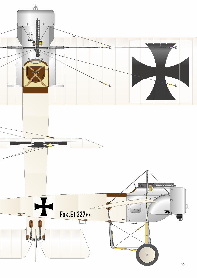
FOKKER E.I “EINDECKER”Full-size Model 1:2,5 (40%) ScaleWingspan 10.05m 402cmLength 6.95m 278cmWeight — 20kgWing surface 16m2 254dm2 approxWing loading — 80gr/dm2 approxEngine 80hp Oberursel Valach VM120 B2-4T rotary engine
3-View DrawingScale: 1:25
Scale to the model: 1:10
29
6 MM PLY
6 MM PLY
6 MM PLY
6 MM PLY
6 MM PLY
30
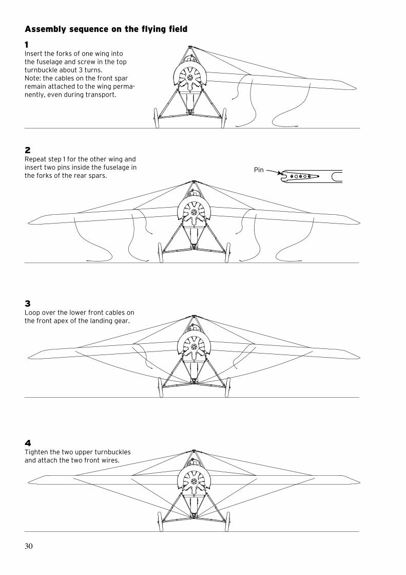
1Insert the forks of one wing into the fuselage and screw in the top turnbuckle about 3 turns.Note: the cables on the front spar remain attached to the wing perma-nently, even during transport.
2Repeat step 1 for the other wing and insert two pins inside the fuselage in the forks of the rear spars.
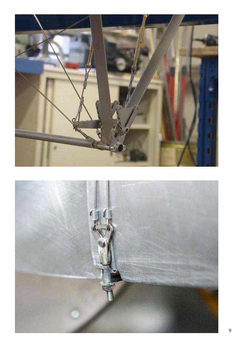
3Loop over the lower front cables on the front apex of the landing gear.
4Tighten the two upper turnbuckles and attach the two front wires.
Pin
Assembly sequence on the flying field

31
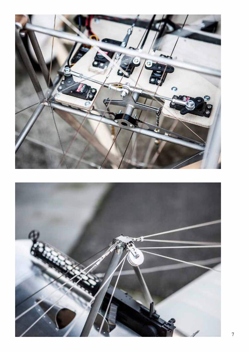
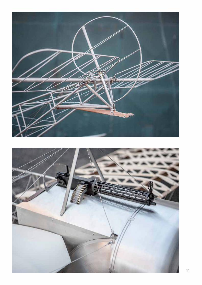
5Place the engine on a large sponge cushion, attach the lower cables to the wing. This cables remain per-manently attached to the warping bellcrank even during the transport.
6Attach the two upper cables and tighten the turnbuckles.Note: These two cables remain permanently inserted in the pulleys, even during transport of the model and the turnbuckles of a end, re-main locked even during transport.
To mount the model only 4 turnbuc-kles require adjusting, the two main turnbuckles of the front cables, and the two at one end of the cables that pass in the pulleys.
7Mount the tail plane and rudder.
Note:If you want you can remove the two pins from the forks, in case of a hard landing, the rear fork may spring out and the fuselage and wing will remain undamaged.Therefore after a hard landing, before the next flight please check to ensure the forks are still in place.

FOKKER E.I EINDECKER 1:2,5 SCALE (40%)Wingspan: 4.02 m (13.19 ft)
Length: 2.73 m (8.95 ft)
Wing area: 3.00 qm (32,3 sq-ft) approx.
Weight: 18/20 kg (40/44 lb)
Engine: Valach Motors VM 120B2-4T, 120 cc - Moki radial 5 cyl. 180 cc or similar.
Designed and engineered by Paolo Severin, in consultation with Gerhard Reinsch from August 2013 to May 2014
www.paoloseverin.it
Paolo Severin srl
Via Decorati al Valor Civile 57a
35142 Padova - Italy
Workshop: Via Monfalcone 11 - Padova
Tel. 049 8800329 - Fax 049 8800354
email: [email protected]
U.S. distributor:
www.vogelsang-aeroscale.com
German distributor:
www.toni-clark.com
Japanese distributor:
www.rcdepot-jp.com