follow diagram below for electrical the pinnacle mini ...2) a protective film has been provided with...
TRANSCRIPT

Please see reverse for Technical Specifications
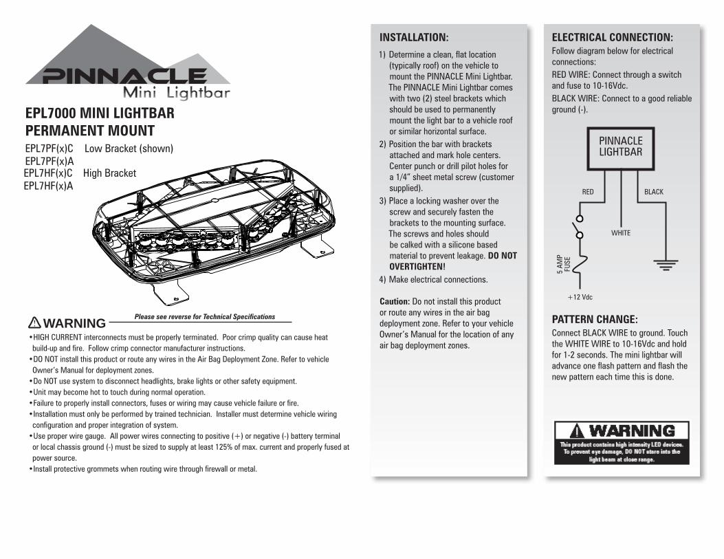
ELECTRICAL CONNECTION:Follow diagram below for electrical connections:RED WIRE: Connect through a switch and fuse to 10-16Vdc.BLACK WIRE: Connect to a good reliable ground (-).
PATTERN CHANGE:Connect BLACK WIRE to ground. Touch the WHITE WIRE to 10-16Vdc and hold for 1-2 seconds. The mini lightbar will advance one flash pattern and flash the new pattern each time this is done.
INSTALLATION: 1) Determine a clean, flat location
(typically roof) on the vehicle tomount the PINNACLE Mini Lightbar.The PINNACLE Mini Lightbar comeswith two (2) steel brackets whichshould be used to permanentlymount the light bar to a vehicle roofor similar horizontal surface.
2) Position the bar with bracketsattached and mark hole centers.Center punch or drill pilot holes fora 1/4” sheet metal screw (customersupplied).
3) Place a locking washer over thescrew and securely fasten thebrackets to the mounting surface.The screws and holes shouldbe calked with a silicone basedmaterial to prevent leakage. DO NOTOVERTIGHTEN!
4) Make electrical connections.
Caution: Do not install this product or route any wires in the air bag deployment zone. Refer to your vehicle Owner’s Manual for the location of any air bag deployment zones.
RED BLACK
WHITE
5 AM
P FU
SE
+12 Vdc
PINNACLE LIGHTBAR
EPL7000 MINI LIGHTBAR PERMANENT MOUNTEPL7PD(x)C Low Bracket (shown)EPL7HD(x)AEPL7HD(x)C High BracketEPL7HD(x)A
•HIGH CURRENT interconnects must be properly terminated. Poor crimp quality can cause heat build-up and fire. Follow crimp connector manufacturer instructions.•DO NOT install this product or route any wires in the Air Bag Deployment Zone. Refer to vehicleOwner’s Manual for deployment zones.
•Do NOT use system to disconnect headlights, brake lights or other safety equipment.•Unit may become hot to touch during normal operation.•Failure to properly install connectors, fuses or wiring may cause vehicle failure or fire.•Installation must only be performed by trained technician. Installer must determine vehicle wiringconfiguration and proper integration of system.
•Use proper wire gauge. All power wires connecting to positive (+) or negative (-) battery terminalor local chassis ground (-) must be sized to supply at least 125% of max. current and properly fused atpower source.
•Install protective grommets when routing wire through firewall or metal.
WARNING
PMB3BKT Replacement Permanent Mount Bracket (each)PMB3BRKT Replacement Permanent Mount Bracket (kit)PMB3TDC EPL7000 Replacement Clear Dome
Replacement Parts & Accessories:
TECHNICAL SPECIFICATIONS
Overall Dimensions: 14.25”L x 8.27”W x 2.93”H
Flash Patterns: 28 flash patterns
Input Voltage Range: 10 - 16 Vdc
Current Consumption: 2 Amps (Avg) - 4 Amps (Max)
# of LEDs: 24 Generation 3 LEDs
Operating Temperature: -40º to +65º C
Cord Length: 300”
Flash Patterns
Alternating PatternsFPM
(Flashes per Minute)
1. Warp Alternating
2. Quad “
3. Quad2 “
4. Quint “
5. Double2 “
6. Warp 1, 2, 3 “
7. Progressive “
8. Q-Switch™ “
9. Intercycle “
10. Warp Whole Bar
11. Quad “
12. Quad2 “
13. Quint “
14. Double2 “
15. Warp 1, 2, 3 “
16. Progressive “
17. Warp Diagonal
18. Quad “
19. Quad2 “
20. Quint “
21. Double2 “
22. Warp 1, 2, 3 “
23. Progressive “
24. Q-Switch “
25. Intercycle “
26. Rotator “
27. Cycle 1 Random
28. Cycle 2 “
EPL7000 MINI LIGHTBAR PERMANENT MOUNTEPL7PD(x)C Low Bracket (shown)EPL7HD(x)AEPL7HD(x)C High BracketEPL7HD(x)A
Please see reverse for Technical Specifications
ELECTRICAL CONNECTION:Follow diagram below for electrical connections:RED WIRE: Connect through a switch and fuse to 10-16Vdc.BLACK WIRE: Connect to a good reliable ground (-).
PATTERN CHANGE:Connect BLACK WIRE to ground. Touch the WHITE WIRE to 10-16Vdc and hold for 1-2 seconds. The mini lightbar will advance one flash pattern and flash the new pattern each time this is done.
INSTALLATION: 1) Determine a clean, flat location
(typically roof) on the vehicle tomount the PINNACLE Mini Lightbar.The PINNACLE Mini Lightbar comeswith two (2) steel brackets whichshould be used to permanentlymount the light bar to a vehicle roofor similar horizontal surface.
2) Position the bar with bracketsattached and mark hole centers.Center punch or drill pilot holes fora 1/4” sheet metal screw (customersupplied).
3) Place a locking washer over thescrew and securely fasten thebrackets to the mounting surface.The screws and holes shouldbe calked with a silicone basedmaterial to prevent leakage. DO NOTOVERTIGHTEN!
4) Make electrical connections.
Caution: Do not install this product or route any wires in the air bag deployment zone. Refer to your vehicle Owner’s Manual for the location of any air bag deployment zones.
RED BLACK
WHITE
5 AM
P FU
SE
+12 Vdc
PINNACLE LIGHTBAR
EPL7000 MINI LIGHTBAR PERMANENT MOUNTEPL7PF(x)C Low Bracket (shown)EPL7PF(x)AEPL7HF(x)C High BracketEPL7HF(x)A
•HIGH CURRENT interconnects must be properly terminated. Poor crimp quality can cause heat build-up and fire. Follow crimp connector manufacturer instructions.•DO NOT install this product or route any wires in the Air Bag Deployment Zone. Refer to vehicleOwner’s Manual for deployment zones.
•Do NOT use system to disconnect headlights, brake lights or other safety equipment.•Unit may become hot to touch during normal operation.•Failure to properly install connectors, fuses or wiring may cause vehicle failure or fire.•Installation must only be performed by trained technician. Installer must determine vehicle wiringconfiguration and proper integration of system.
•Use proper wire gauge. All power wires connecting to positive (+) or negative (-) battery terminalor local chassis ground (-) must be sized to supply at least 125% of max. current and properly fused atpower source.
•Install protective grommets when routing wire through firewall or metal.
WARNING

PMB3BKT Replacement Permanent Mount Bracket (each)PMB3BRKT Replacement Permanent Mount Bracket (kit)PMB3TDC EPL7000 Replacement Clear Dome
Replacement Parts & Accessories:
TECHNICAL SPECIFICATIONS
Overall Dimensions: 14.25”L x 8.27”W x 2.93”H
Flash Patterns: 28 flash patterns
Input Voltage Range: 10 - 16 Vdc
Current Consumption: 2 Amps (Avg) - 4 Amps (Max)
# of LEDs: 24 Generation 3 LEDs
Operating Temperature: -40º to +65º C
Cord Length: 125.75”
Flash Patterns
Alternating PatternsFPM
(Flashes per Minute)
1. Warp Alternating
2. Quad “
3. Quad2 “
4. Quint “
5. Double2 “
6. Warp 1, 2, 3 “
7. Progressive “
8. Q-Switch™ “
9. Intercycle “
10. Warp Whole Bar
11. Quad “
12. Quad2 “
13. Quint “
14. Double2 “
15. Warp 1, 2, 3 “
16. Progressive “
17. Warp Diagonal
18. Quad “
19. Quad2 “
20. Quint “
21. Double2 “
22. Warp 1, 2, 3 “
23. Progressive “
24. Q-Switch “
25. Intercycle “
26. Rotator “
27. Cycle 1 Random
28. Cycle 2 “
EPL7000 MINI LIGHTBAR PERMANENT MOUNTEPL7PF(x)C Low Bracket (shown)EPL7PF(x)AEPL7HF(x)C High BracketEPL7HF(x)A

Please see reverse for Technical Specifications
INSTALLATION:1) Detemine a clean, flat location
(typically the roof) on the vehicle tomount the PINNACLE Mini Lightbar.The PINNACLE Mini Lightbar comesequipped with four magnetic feet. Itis the responsibility of the installerand end user to determine whetherit is safe to use magnetic mountinghardware for your application.A Permanent Mount version(EPL7PD(x)C) is available.Note: The magnetic character of roofsteel varies from vehicle to vehicle.Be sure that your vehicle is capableof providing enough magnetic forceto safely secure the PINNACLE MiniLightbar to the roof.
2) A Protective Film has been providedwith the PINNACLE Mini Lightbar kitthat can be applied to the bottom ofeach magnet. This film will protectthe paint of the vehicle. Apply onedonut shaped decal to the bottom ofeach magnetic foot. Be sure to coverthe magnet entirely for maximumprotection to the paint finish.Note: Protective film can reduce themagnetic force by as much as 10%.
EPL7000 PINNACLE MINI LIGHTBAR MAGNET MOUNTEPL7SAM+(x)C
OPERATION:Electrical Connections & Flash Pattern Selection:
See diagram at left for Power ON ( ), Power OFF ( ) and Pattern SELECT ( ) switch positions. Turn the light on by pressing the Power ON button. To change the flash pattern press and hold the PATTERN SELECT button for one to two (1-2) seconds. The PINNACLE Mini Lightbar will advance one (1) flash pattern and flash the new pattern each time this is done. The PINNACLE Mini Lightbar features non-volatile memory and will recall last pattern used. Selected pattern will remain the default once turned off and can be changed by changing the flash pattern before powering off.
Power ONPower OFFPattern SELECT
EPL7SAM+(x)A
•HIGH CURRENT interconnects must be properly terminated. Poor crimp quality can cause heatbuild-up and fire. Follow crimp connector manufacturer instructions.
•DO NOT install this product or route any wires in the Air Bag Deployment Zone. Refer to vehicleOwner’s Manual for deployment zones.
•Do NOT use system to disconnect headlights, brake lights or other safety equipment.•Unit may become hot to touch during normal operation.•Failure to properly install connectors, fuses or wiring may cause vehicle failure or fire.•Installation must only be performed by trained technician. Installer must determine vehicle wiringconfiguration and proper integration of system.
•Use proper wire gauge. All power wires connecting to positive (+) or negative (-) battery terminalor local chassis ground (-) must be sized to supply at least 125% of max. current and properly fused atpower source.
•Install protective grommets when routing wire through firewall or metal.
WARNING