follow these flow best practices - chemical processing · flow best practices. 2 elements we’re...
TRANSCRIPT


22
ELEMENTSW E ’ R E E N H A N C I N G T H E
O F S T R E N G T H .
Enhance the strength of your next industrial job. Visit corzancpvc.com or call a piping systems consultant at 1.855.735.1431.
Corzan® Industrial Systems get their strength from our science. That’s because The Lubrizol Corporation’s superior CPVC compounds create every Corzan pipe and fi tting. With the power of mechanical strength and corrosion resistance, Corzan pipe and fi ttings exceed the demands of industrial and commercial applications. Plus, every Corzan system has delivered MORE INSIDE™ for more than 20 years—giving you access to Lubrizol’s unmatched R&D, technical expertise, global capabilities and a network of customers who are industry-leading manufacturers.
Follow us on Twitter @LZ_CPVC
© 2014 The Lubrizol Corporation, all rights reserved. All marks are the property of The Lubrizol Corporation.The Lubrizol Corporation is a Berkshire Hathaway company.GC 121100

Indoor Venting Helps Manage Combustible Dust Explosion RisksAnalyzer measures concentration, density and mass flow rates in real-time
THE ulTRasonIC clamp-on process analyzer PIOX® S is used to measure con-centration, density and mass flow rates of a liquid in real-time by determining the acoustic velocity of the medium.
PIOX S transfers the practical advantages of clamp-on ultrasonic technology to process analytical applications. Because the transducers are mounted on the – safe – outside of the pipe, they are not subject to any wear and tear by the medium flowing inside. Moreover, as there is no need to open the pipe for installation, mounting and initial operation can usually be done during ongoing operation. Non-invasive process analytics with PIOX S are suitable for almost all pipe sizes and materials — whether it’s steel, plastic, glass or special materials with inline or outer coatings, in a nominal size range of ¼ in. to 20 ft, for temperatures up to 750°F as well as for hazardous areas. The transducers and transmitters also are available in FM-certified designs.
PIOX S is said to be ideal for materials and processes that demand the highest levels of safety and reliability, e.g. in the case of corrosive media like strong acids or alkalis or even toxic compounds.
www.flexim.com/us/piox-s
3
TablE oF ConTEnTsleaks Don’t lie 7Treat them as calls for action against the underlying problem
Consider VFDs for Centrifugal Pumps 10Such drives may provide energy savings and avoid operating problems
Mining operations unearth big benefits 14Piping made of high-performance plastic provides unmatched performance and longevity
Consider Ceramic in Electromagnetic Flow Meters 19Material used for measuring tubes offers high performance, longevity and a host of other benefits
PRoDuCT RElEasEsIndoor Venting Helps Manage Combustible Dust Explosion Risks 3
ball Valves suit lead-Free Press systems 5
Wireless Transmitter simplifies Installation 8

44
Featuring a unique ceramic construction, the OPTIFLUX 5000 handlesthe toughest fluids.
Excellent long term stability and the best accuracy available anywhereFused in place Cermet or platinum electrodes in a fully vacuum resistant high tech ceramic linerSuitable for most aggressive and abrasive fluids - acidic, alkaline, pastes, slurries and corrosive media, even with high solid contentsAlso used in chemical injection for precise dosing of additives or as a calibration referenceAvailable in sizes 1/2” to 12” in sandwich or flanged designs
KROHNE – process measurement engineering is our world.
OPTIFLUX 5300 Cwith stainless housing
[email protected]: 1-800-FLOWINGus.krohne.com
For the most challenging flow applications -It stands alone

55
lubrizol 2www.corzancpvc.com
Krohne 4www.us.krohne.com
Parker | Porter 6www.porterinstrument.com
Viega 9www.viega.us
Federal Equipment Co. 11www.fedequip.com
Emerson 13www.rosemount.com/fullpotential
Flexim 18www.flexim.com
almatec 23www.almatec.de
aD InDEx
ball Valves suit lead-Free Press systemsNew line incorporates unique silicon-bronze alloy engineered for press technology
VIEga oFFERs a line of press ball valves manufactured from material specifically designed for lead-free press systems. Made from Viega’s unique silicon-bronze alloy, engineered for press technology, Viega ProPress® Zero Lead™ ball valves provide the same quality, reliability and performance as all Viega press fittings. Certified to ASME A112.4-2004 and NSF-61G in sizes from ½ in. to 2 in., Viega ProPress Zero Lead ball valves are suitable for use with Viega ProPress fittings in copper for potable water applications.
www.viega.us

66
Together, we can help you get the most out of your process.Our after-sale support team is always on-call to help you streamline your installation, setup or field calibration. That’s the Porter Promise.Process industry professionals say:
“When I use Parker Porter products based on the selection criteria provided, I don’t have to worry. It always works!”
“An actual person is ready to help – priceless in this industry!” • A comprehensive range of flow and pressure technologies • Knowledgeable application engineering support • Dependable just-in-time deliveryTo ensure peace of mind and process reliability, visit us today at PorterInstrument.com.

77
leaks Don’t lieTreat them as calls for action against the underlying problem
Dirk Willard, Contributing Editor
on augusT 6, 2012, firemen and a work crew were investigating a leak in the light-gas-oil side-cut line of the crude atmospheric tower at Chevron’s Richmond, Calif., refinery. An operator suggested shutting down the unit for repairs but was over-ruled. Firemen were instructed to pin-point the leak under the insulation, which they proceeded to do — with a fire hook. The firemen smashed a hole in the thinned pipe and then blasted the pipe with cold water to break loose the insulation. The pipe burst and 640°F oil spilled and ignited. This accident nearly incinerated a fire-man and has cost Chevron $12 million so far.
Chevron had been replacing this corroded line and others connected to it but, obviously, not fast enough. Leaks were evident. During an inspection after the ac-cident, Cal-OSHA found nine clamps to stop leaks.
Unfortunately, Chevron isn’t alone in such misfor-tune. On December 7, 2009, a high-pressure reactor at NDK Crystal’s plant in Belvedere, Ill., ruptured, killing a truck driver 650 feet away. In this case, nearby reactors had leaked before — in 2003, 2006 and 2009. NDK was convinced that a protective coating formed inside the 8-in.-thick reactor walls protected these vessels.
NDK never qualified this “theory” or inspected vessel interiors. Neither the state of Illinois nor the company’s insurer challenged the theory, though. Illinois granted NDK a waiver from complying with the ASME code: the thickness of the wall made inspection and fabrica-tion problematic. The Belvedere site remains closed.
What links these two accidents together? Leaks pro-vided adequate warning that something was very wrong.
So, what’s the best way to approach a leak? Obvi-ously, the first line of defense is vigorous inspection. Chevron, to its credit, did that; NDK did not. (The fatal 2010 fire and explosion at Tesoro’s Anacortes, Wash., refinery also was linked to poor inspection.)
Second, always evaluate whether to continue operat-ing once a leak is detected. Who at Chevron and NDK decided to keep the units running?
Chevron had more warning, but slapping a clamp on a leak is a common practice at most refineries. Chevron had used clamps before, building confidence that this approach was sound. (For more on the perils of stopgap repairs, see “Fear Ad Hoc Fixes,” www.ChemicalProcessing.com/articles/2013/operational-safety-and-maintenance-fear-ad-hoc-fixes/.) Let’s
RElaTED ConTEnT on CHEMICalPRoCEssIng.CoM“Prepare to Clamp Down Tighter on Leaks,” www.ChemicalProcessing.com/articles/2010/098/“Plants Look Harder for Leaks,” www.ChemicalProcessing.com/articles/2012/plants-look-harder-for-leaks/

88
hope regulators and operating companies are doing some soul-searching to understand the risks of temporary solutions.
Now, imagine you were the maintenance manager at Richmond assigned to seal the leak. Assume you can’t shut down the refinery, because that’s normally the case. Perhaps operations can do something such as cut the tower rate, or cool or heat the tower temporarily to reduce the side draw. Ask. Work out a cooperative plan.
Start by reviewing the work done recently and in the past on the pipe and vessel: look at the inspection reports, marked-up isometrics, hazard and operability studies, etc. Talk with the inspectors and include them in the preparation. You now know this pipe is fragile. The process and instrumentation drawings don’t show isola-tion valves; besides, even if they did, you don’t know when these valves were operated last.
So, you have a delicate pipe and must remove the insulation to inspect it. How will you pull the insula-tion off without endangering your crew? Involve them in developing the job plan. What is your backup plan if the leak gets worse? How will the crew egress? What other equipment will be affected? What will you do if
insulation removal doesn’t expose the leak point? Who is qualified to do the job? Consider how the crew’s actions could affect their safety and the success of job. Finish the draft and review it. Ask the inspectors to look over the job plan, too.
Ideally, you should have written a template for this plan months ahead as a maintenance standard operating procedure. This is a common practice at Dow Chemical and elsewhere.
Before work begins, brief your crew: no heroics, and no deviations from the plan. Establish a rapport with operations — what are they expected to do to support the crew? If the job goes sour, what will operations do to shut down the tower and reduce pipe f low? Do they have enough people to quickly isolate the tower? Are refinery safety and communications people in the loop on the work? Are nearby units aware of and prepared for what’s going on? What about contractors and others off the refinery radio network?
DIRK WIllaRD, Contributing Editor
Wireless Transmitter simplifies InstallationDevice measures two process variables without increasing installation costs
EMERson PRoCEss Management introduces the Rosemount 3051S MultiVariable wire-less pressure transmitter, designed to directly measure two process variables in one installation so users can gain greater insight into their process without increasing installation costs.
The more devices in a facility, the greater the required cost and time investments for installa-tion, scheduled maintenance and downtime. Now users can simplify installation and maintenance routines with the Rosemount 3051S MultiVariable Wireless Pressure Transmitter. Because the transmitter measures differential and static pressure, users can reduce pipe penetrations and im-pulse piping along with their associated costs. The static pressure sensor is available as either true gage or absolute which allows for reduced maintenance and calibration costs.
With Rosemount 3051S wireless transmitters, users can monitor more assets throughout their facilities with greater than 99% reliability and at 40 to 60% cost savings over wired installations.
The wireless pressure transmitter delivers a decade of maintenance-free performance with a 10-year stability specification, making it the most cost effective and reliable way to monitor assets while reducing installation costs.
www.rosemount.com/3051sMVWireless

99
The g loba l leaderin p lumbing, heat ing
and p ipe jo in ing systems
Viega ProPress ball valvesDesigned for con� dence
Introducing ViegaProPress® ball valves
Viega is the only manufacturer with a line of lead-free ball valves speci� cally designed for press technology. Made from our unique silicon-bronze alloy, engineered speci� cally for press systems, these ball valves provide the same quality, reliability and performance as all of our Viega ProPress � ttings.
Viega ProPress ball valve features• Multiple confi gurations,
P x P, P x FPT and P x Hose Thread
• 316 stainless steel ball standard
• Choice of P x P valve stem in Eco Brass® or 316 stainless steel
• Available in sizes from ½" to 2"
Zero Lead refers to product complying with NSF 61-G
Introducing new Viega ProPress®
ball valves in Zero Lead™
www.viega.us | 1-800-976-9819

1010
Consider VFDs for Centrifugal PumpsSuch drives may provide energy savings and avoid operating problems
Andrew Sloley, Contributing Editor
VaRIablE FREquEnCy drives (VFDs) offer a useful control option for the motors of many types of recip-rocating and centrifugal equipment. For instance, VFDs can deal with centrifugal-pump suction recircula-tion problems; running at lower speed can help reduce damage and operating difficulties.
To understand how to apply VFDs effectively, you must know the characteristics of the system and the equipment. So, let’s look at a general procedure that can serve as a good starting point for evaluating specific cases — realizing, of course, that it can’t cover every possibility.
To evaluate a VFD application, we need the following:
• system information on pressure drop versus flow;
• pump performance curves for the existing impeller;
• pump performance curves for the maximum impeller; and
• pump inlet eye dimensions.
Ideally, the performance curves should include pump head, pump ef-ficiency and net positive suction head (NPSH) required versus flow rate. Pump heads and efficiencies at various speeds are useful.
Often, only incomplete information is available. So, you may need to ex-trapolate to fill in missing information.
analysIs PRoCEDuRE
A VFD evaluation involves multiple steps, each looking at a specific item. Below are the basic steps. (Some cases won’t need every step while others may require additional ones. The informa-tion available and needed as well as the number of cases to be evaluated determine what must be done.)
0 4,000 8,000 12,000 16,000 20,000Suction Specific Speed, Nss
Flo
w, U
S G
PM
Frac
tio
n o
f B
EP
Flo
w
160
120
80
40
0
0.8
0.6
0.4
0.2
0
Actual flow versus Nss
Flow fraction of BEP flow versus Nss actual pump
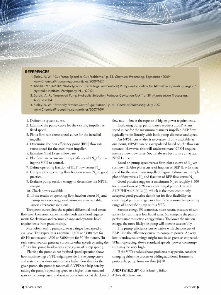
Figure 1. Combined plot shows both flow and fraction of BEP flow versus Nss.
FloW RElaTIonsHIPs

1111
Contact Us At 1.800.652.2466 or by Email at [email protected] to get a Fast Quote. View Our Entire Inventory Online at www.fedequip.com
(877) 536-1538 or www.fedequip.com
Pharmaceutical, Chemical, and Plastics Manufacturing Equipment
• Blister Lines• Bottling Lines • Capsule Fillers • Centrifuges
• Coating Pans• Dryers• Filters• Fluid Bed Dryers
• Fluid Bed Granulators• High Shear Mixers• Lab Equipment• Mixers
• Tablet Presses• Tanks• Roller Compactors
Federal Equipment Company has more than 50-years experience in the processing equipment industry, providing quality used equipment, outstanding service, and competitive prices to chemical, pharmaceutical, plastics, and related process industries. Major markets include API, speciality and fine chemical, bulk chemical, and pharmaceutical and biopharmaceutical manufacturing, including solid dose, liquids, powders, aseptic filling, and packaging.
In addition to thousands of pieces of equipment in stock and ready to ship, Federal Equipment offers specialized services including the liquidation and auction of process lines and manufacturing facilities, equipment appraisals, rigging, testing, and auction services, as well as managing the negotiated liquidation of surplus equipment.
8200 Bessemer Ave. • Cleveland, Ohio 44127 • T (800) 652-2466 www.fedequip.com • [email protected]
39” APV Pilot Spray Dryer, S/S 10 Liter GEA Collette NV High Shear Mixer, UltimaGral 10, 316 S/S
Your Source for Pfizer Surplus Equipment
Federal Equipment is your source for Pfizer process and packaging equipment. Go to fedequip.com and check out the latest additions to our inventory from Pfizer sites around the world.
Buy the best, from the best!
Visit us at INTERPHEX 2013 at the Javits Center in New York, Booth 1952
THE SOURCE ... for Pharmaceutical, Chemical, Plastics, and Related Process Equipment.
1212
1. Define the system curve.2. Examine the pump curve for the existing impeller at
fixed speed.3. Plot a flow rate versus speed curve for the installed
impeller.4. Determine the best efficiency point (BEP) flow rate
versus speed for the maximum impeller.5. Examine NPSH versus flow rate.6. Plot flow rate versus suction specific speed (Nss) for us-
ing the VFD to control.7. Define operating fraction of BEP flow versus Nss.8. Compare the operating flow fraction versus Nss to good
practice.9. Evaluate pump suction energy to determine the NPSH
margin.10. Check power available.11. If the results of operating flow fraction versus Nss and
pump suction energy evaluation are unacceptable, assess alternative solutions.
The system curve plots the required differential head versus flow rate. The system curve includes both static head require-ments for elevation and pressure change and dynamic head requirements from pressure drop.
Most often, only a pump curve at a single fixed speed is available. This typically is a nominal 1,800 or 3,600 rpm for 60-Hz motors and 1,500 or 3,000 rpm for 50-Hz motors. (In such cases, you can generate curves for other speeds by using the affinity law: pump head varies as the square of pump speed.)
Plotting the pump curve for fixed-speed operation shows how much savings a VFD might provide. If the pump curve and system curve don’t intersect at a higher flow than for the given pump, the pump is too small. A VFD can help here by raising the pump’s operating speed to a higher-than-standard rpm so the pump curve and system curve intersect at the desired
flow rate — but at the expense of higher power requirements.Evaluating pump performance requires a BEP versus
speed curve for the maximum diameter impeller. BEP flow typically varies linearly with both pump diameter and speed.
An NPSH curve also is necessary. If only available at one point, NPSH can be extrapolated based on the flow rate squared. However, this will underestimate NPSH require-ments at low flow rates. So, it’s always best to use an actual NPSH curve.
Based on pump speed versus flow, plot a curve of Nss ver-sus flow [1]. Also plot a curve of fraction of BEP flow (at that speed for the maximum impeller). Figure 1 shows an example plot of flow versus Nss and fraction of BEP flow versus Nss.
Good practice suggests a maximum Nss of roughly 8,500 for a turndown of 50% on a centrifugal pump. Consult ANSI/HI 9.6.3-2012 [2], which is the most commonly accepted good-practice definition for flow flexibility on centrifugal pumps, to get an idea of the reasonable operating range of a specific pump with a VFD.
Suction energy [3] is another, more recent, measure of suit-ability for running at low liquid rates. So, compare the pump performance to suction energy values. The lower the suction energy, the more likely the pump will operate successfully.
The pump efficiency curve varies with the percent of BEP. Use the efficiency curve to compute power. At very low turndowns, savings might not be as great as expected. When operating above standard speeds, power consump-tion may be very high.
If the VFD analysis shows problems may persist, consider changing either the process or adding additional features to protect the pump from low flow [4].
anDREW slolEy, Contributing Editor
REFEREnCEs1. Sloley, A. W., “Cut Pump Speed to Cut Problems,” p. 33, Chemical Processing, September 2009,
www.ChemicalProcessing.com/articles/2009/167/.2. ANSI/HI 9.6.3-2012, “Rotodynamic (Centrifugal and Vertical) Pumps — Guideline for Allowable Operating Region,”
Hydraulic Institute, Parsippany, N.J. (2012).3. Burdis, A. R., “Improved Pump Hydraulic Selection Reduces Cavitation Risk,” p. 39, Hydrocarbon Processing,
August 2004.4. Sloley, A. W., “Properly Protect Centrifugal Pumps,” p. 42, ChemicalProcessing, July 2007,
www.ChemicalProcessing.com/articles/2007/109/.

1313
The Emerson logo is a trademark and a service mark of Emerson Electric Co. © 2013 Emerson Electric Co.
Discover new efficiencies and achieve unmatched throughput with Rosemount® instrumentation. Turn to Emerson measurement experts and Rosemount instrumentation to get more production out of your current equipment, maintain a smarter workflow and operate at your full potential. Our specialists will show you how to use stable, accurate instruments to minimize measurement drift and confidently run your facility as close as possible to critical levels. And with intuitive diagnostic tools and wireless transmitters, you can gather more detailed insights into the health of your entire process without adding infrastructure, so you can stay optimized longer and avoid downtime. To learn how Emerson can help you hit your production targets and maximize the capacity of your assets with measurement instrumentation, see case studies at Rosemount.com/fullpotential
YOU CAN DO THATI get measured on hitting my production targets. I need to get more out of my assets so I can meet my performance goals.
View video with our take on efficiency.

1414
CoRRosIon Is the enemy of metallic piping systems everywhere. The slow deterioration of pipes by water, chemicals or other fluids spells the inevitable end of metallic systems across the globe. It’s not a question of “will my pipes fail?” or even “when will my pipes fail?” but “how soon will my pipes fail?”
Due to this prevalence of corrosion, it’s not uncommon for industrial facility maintenance managers to have low expectations of their piping systems. Lifespan expectancies of metallic pipes range anywhere from just a few months to around five years —necessitating frequent maintenance and replacement, driving up costs and becoming a major operational hassle.
The solution is Corzan HP industrial piping systems. Engineered with Lubrizol CPVC (chlorinated polyvinyl chloride) compounds, Corzan HP provides a high-pressure, high-impact, high-temperature-strength piping system. Lubr-izol’s CPVC technology gives Corzan unmatched corrosion resistance that eliminates pitting and scaling while providing superior life-cycle benefits.
Harsh chemicals flow through Corzan HP piping inside Grupo Mexico’s copper refinery metallurgical complex in Nacozari Sonara, Mexico, on a daily basis. The plant’s opera-tions include copper refining and wire rod, precious metals and effluents treatments, and Luis Antonio Nuñez Acosta, the complex’s maintenance manager, reports the performance of piping throughout has exceeded expectations.
“The refinery processes the anodic copper by electrolysis,” says Acosta. “We have operated with Corzan HP industrial systems without interruption for 15 years, with mechanical integrity and free of maintenance.”
bEyonD ExPECTaTIons
Mitigating corrosion and minimizing maintenance was a critical concern when Grupo Mexico built the Nacozari Sonara complex in 1997, which factored heavily into the
decision to utilize Corzan HP. The use of CPVC pipes was considered from the design phase of the plant in order to convey the highly corrosive fluids with a very low pH and at a temperature in the region of 65°C, all of which are impor-tant factors in the selection of material.
PVC was ruled out because of operational deficiencies such as rapid aging and a temperature limit of 60°C. The op-tion of metallic piping — both carbon steel and stainless steel — also was ruled out because of the chemical and galvanic corrosion generated in the electrolytic process. It became clear to the plant’s designers that Corzan HP industrial systems was the most viable option due to its high performance in conveying liquid chemicals at temperatures above 90°C, as well as its anti-corrosive qualities.
As the facility was built (Figure 1), Corzan HP was used for 80% of the piping installed throughout the plant, rang-ing from 1 in. to 16 in. The remaining 20% of the plant’s system is made up of polypropylene piping. However, Gru-po Mexico has made plans to convert that remaining 20% to Corzan HP because of consistent leaks that have plagued the thermo-fused joints of the polypropylene portion of the system. Polypropylene is a softer material than CPVC, and in applications like this one, trouble can arise due to the material’s expansion and contraction. Additionally, as polypropylene gets hotter (whether due to sun exposure or heat conditions inside the facility in which the material is being used), its joints run into trouble. By comparison, Cor-zan HP pipe and fittings are joined using a solvent welding process, which molecularly fuses the material, ensuring that leaks won’t be a problem in the long run.
Corzan HP has also helped the facility stack up additional operational savings with its constant surface roughness of C=150 on the Hazen-Williams equation, providing lower fric-tion loss than commonly used pipes.
“The advantages we found in using Corzan HP are due to the fact that the maintenance is virtually nil,” Acosta notes.
Mining operations unearth big benefitsPiping made of high-performance plastic provides unmatched performance and longevity
By Jorge Solorio, Lubrizol Advanced Materials, Inc.

1515
“Other factors that contribute are the significant reduction in scaling (a roughness coefficient of the smooth inner surface) and resistance to internal and external corrosion.”
And so far, it’s been 15 maintenance-free years.
CoRRosIon anD oTHER PRoblEMs
While corrosion issues may be the most prominent failing of metallic pipes inside a chemical processing plant, mining facility, etc., it’s not the only issue that can hurt the perfor-mance of an industrial piping system.
Rigidity of pipes in these sorts of facilities is necessary and important in the reduction of sediment buildup, which can drastically shorten lifespans. Metallic pipes are prone to sag-ging, causing increased sediment to rest at the bottom, hin-dering performance and necessitating early replacement. The rigidity in Corzan HP pipes helps to alleviate these issues.
Preventing leaks is a high priority for mining and chemi-cal facilities as well. Miguel Avalos, engineer, general and
projects director ATIC Asesoria Tecnuca y Control, S.A. de C.V. for First Majestic Silver Corp.’s Del Toro plant in Zacatecas, Mexico, said that the goal of a Corzan HP instal-lation at the facility was to achieve zero leaks, zero scaling and zero sediment buildup.
Reagents aren’t cheap; leak prevention presents a signifi-cant cost savings for the company. The plant installed more than 7 km of Corzan HP CPVC piping and estimates that the investment would be recovered in less than one year.
This cost savings can be attributed to a number of factors. The maintenance of a metal reagent piping system is expensive — and pipes must be frequently replaced in their entirety due to their susceptibility to corrosion and scaling. Acids and other corrosive chemicals cause constant wear and tear on the system, which requires high maintenance costs in order to prevent leaks.
“We installed the Corzan HP CPVC system to convey reagents, including the sodium cyanide used in extracting gold and silver,” Avalos says. The extraction process is con-
Figure 1. Corzan HP Industrial Piping Systems was used for 80% of the piping installed throughout Grupo Mexico’s Nacozari Sonara complex. The company has made plans to convert the remaining 20% to Corzan HP.
gRuPo MExICo sITE

1616
ducted by introducing cyanide to the ore, which causes the gold to oxidize and dissolve in the presence of air and water.
This process, called cyanidation, can be highly corrosive to metallic pipes. The process consists of slowly passing a diluted cyanide solution through piles of crushed, ground or agglomerated gold ore. This must be done on an impervious surface that allows the collection of the resulting gold-cyanide solution. As the gold- and silver-enriched impervious surface reaches the impervious floor, it is poured into a storage pond, which then feeds a piping circuit that precipitates the gold and silver from the cyanide.
All of this is handled without issue by the plant’s Corzan HP piping system. In addition to the sodium cyanide, the facility’s Corzan HP pipes are used to convey copper sulphate as an activating agent in the concentration by the floating of lead foam, zinc, cobalt and gold. All that makes for a tough job that Corzan HP pipe and fittings can handle for years.
Corzan HP also enables automatic reagent dosing at the Del Toro plant, helping to create additional efficiencies. Due to its high mechanical properties, Avalos will be installing
14-in. diameter Corzan HP pipes in the mine’s laboratories. In conjunction with the system’s valves, the pipes are used in the scrubber for the extraction of hot gases and dust at temperatures greater than 70°C.
“We decided to replace the metal pipes with Corzan HP because it offers numerous benefits,” says Avalos. “High resistance to the ambient temperature and UV light, it never corrodes and prevents scaling and sedimentation. We have al-ready installed almost 7 km of Corzan HP pipes in diameters ranging from 1 in. to 14 in.”
CosT bEnEFITs oF HIgH-PERFoRManCE CPVC PIPEs
Maintenance managers and other decision makers have two costs to consider when deciding on a new chemical piping system, no matter the application: cost of maintenance and cost of installation.
When replacing a piping system, losses attributable to a facility’s downtime during a retrofit or installation can be far more expensive than the installation itself. For this reason, it’s of great importance to limit the amount of downtime in order to keep production at a maximum.
THE lubRIzol aDVanTagECorzan HP is a member of the Corzan Industrial Systems family of CPVC pipe, fittings and process components that were originally engineered to simplify system design, maintenance and repair with one reliable material solution. Whether 24-in. diameter piping systems, pump/filtration systems or air pollution control systems are needed, Lubrizol can provide a proven, corrosion-resistant solution for the entire process.
Choosing Corzan HP also means receiving access to the full support of the Lubrizol CPVC team, from design to installation. Lubrizol offers its expertise on CPVC piping solutions throughout all segments of the industrial market, from mining and refining applications, to power generation, gas extraction and beyond.
A piping solution from Lubrizol CPVC also means access to the FBC™ System Compatible Program. Chemical com-patibility of Corzan HP with ancillary products — meaning those products the pipes may come in contact with during an installation or otherwise — is important in order to ensure optimal, long-term performance of the system. This isn’t to be confused with a list of products that Corzan HP can safely transport — this information can be found on our manufac-turing partners’ websites.
Corzan HP pipe and fittings are available globally through Lubrizol’s list of manufacturers. Visit corzancpvc.com to find a manufacturer or to locate a Lubrizol CPVC piping systems consultant who can assist with specifications and design recommendations. To speak to a piping systems consultant, call 216-447-7397.

1717
Metallic systems are not the easiest to work with, particularly when dealing with large pipes as is so often the case inside industrial facilities. For instance, suitable iron pipes for such a facility would require heavy lifting equipment like forklifts and dollies, which drives up costs if renting such equipment is necessary. Additional safety concerns begin to come into play when dealing with heavy machinery.
Metallic piping also requires fusing and welding of joints and pipes, and doing so for pipes of this size requires a lot of energy, further driving up costs. It’s a slower, often cumbersome process that can add up to more downtime than anticipated while an installation is performed.
Lubrizol’s Corzan HP, by contrast, does away with each of these concerns, helping drive down costs both in the short and long term. Corzan HP pipes are much lighter weight than comparative metallic pipes, meaning
they don’t require special equipment to lift and install. As well, the two-step solvent welding process used to join Corzan HP pipe and fittings offers a cleaner, safer and faster installation process without the need for hot welding equipment.
As such, the speed and ease of a Corzan HP installation can greatly reduce operational losses that can result from lengthy facility downtime; once a Corzan HP installation is established, as much as 300 m of Corzan HP piping can be installed within a single day. Combined with the lower price point of Corzan HP CPVC materials, it all adds up to signifi-cant cost savings for a facility.
PERFoRManCE bEnEFITs
Corzan HP Schedule 40/80 piping system made from fully pressure-rated materials gives engineers and facility manag-ers a solution that exceeds expectations. Other benefits include:
• Corzan HP piping meets ASTM F441 material classifi-cation 4120-06, with a pressure rating 25% higher than standard CPVC at 180°F (82°C).
• Drop impact strength is up to three times higher than that of standard CPVC piping material.
• Corzan HP offers the highest heat deflection tempera-ture (HDT) of any CPVC piping compound.
• Fitting materials have improved creep resistance and an ability to withstand long-term, high-temperature hydrostatic pressure.
loCaTIon ConCERns anD aDDITIonal usEs
While Corzan HP excels as a piping choice for the trans-mission of chemical fluids, it can also become a part of an industrial facility’s total piping system (Figure 2).
By their very nature, many mining and refining facili-ties are located in remote areas where water is scarce or not readily available. Corzan HP piping can be utilized in a water system and is well suited for downstream water capture. Facilities can utilize Corzan HP CPVC for their water transportation, from the water’s source to a facility’s cleaning operations, and back again.
JoRgE soloRIo is industrial Americas business manager for Lubrizol
Advanced Materials, Inc. He can be reached at [email protected].
Figure 2. Corzan HP Industrial Piping Systems, engineered with Lubrizol CPVC’s superior compounds, provides high-pressure, high-impact, high-temperature-strength systems, offering a corrosion-resistant technology that eliminates pitting and scaling while providing superior lifecycle benefits.
PIPIng sysTEM

1818
© Foto Outotec
PIOX® S
PIOX® S - the evolution of flow and concentration measurement in sulphuric acid production.
PIOX® S already convinced many North American and some of the largest sulfuric acid plants in the world for use in their process control tasks.
Non-intrusive flow and concentration of Sulfuric Acid and flow of Molten Sulfur
www.piox-s.com
www.flexim.com
fNo piping and valving f100% clamp-on fNo media contact - No risk of leaks fNo process Shut-Downs for
installation fNo bypass needed
fFor hazardous area locations (FM approved)
fMonitor your Total Sulfur Consumption
fIncrease your Plant Up-Time
fBalance your Processes
Contact us for a free trial measurement!

1919
THE CHEMICal industry relies on tried and true measuring technology to measure the volume f low of electri-cally conductive media: well over 3 million electromagnetic f low meters (EMFs) are in use all over the world. The demands placed on devices when used in chemical plants are much more stringent than those in the water industry, for example. In addition to the electronics, the design and mea-suring tube material are crucial when it comes to determining whether the EMF is suitable for use in chemical processes. The following properties of the measuring tube material are particularly relevant:
• Corrosion resistance to aggressive media
• Form stability• High resistance to thermal shock• Vacuum resistance, form stability
with under/over pressure• Resistance to abrasion• Diffusion tight• Leakage immunityEven if not normally the case,
sometimes with certain tasks such as measuring nitric acid, several of these properties are required at the same time. The PFA and PTFE linings typi-cally used for EMFs aren’t adequate in this case as they are not acceptably resistant to diffusion. For this reason, EMFs with measuring tubes and measuring tube liners made out of ce-ramic materials have been available for decades for this type of application.
A variety of different device types exist featuring ceramic measuring tubes: in addition to their use with acids and bases in chemistry, the f lowmeters used in bottling machines in the beverage industry are almost ex-clusively equipped with ceramic mea-suring tubes. This is where another of the ceramic properties comes into play: extraordinary low surface rough-ness means good hygienic suitability.
The OPTIFLUX process measur-ing devices used in the chemical in-dustry (Fig 1) feature measuring tubes made of oxide ceramics with a base of aluminium oxide or zirconium oxide. The electrodes are mainly platinum but depending on the application, other materials (Hastelloy, titanium, tantalum) also are used. Variants without wetted metal electrodes, so-called capacitive EMFs, also are available.
MaKIng CERaMIC MEasuRIng TubEs
To understand the special proper-ties of ceramic measuring tubes, you must first understand their design: a measuring tube is a single rotation-symmetric piece from face to face. It’s manufactured as if it were a cast piece. This holds true for nominal sizes up to DN 300, sizes above that are lined with ceramic plates.
The starting material for the mea-suring tubes is an aluminium oxide or zirconium oxide powder featuring spe-cial mineral quality (Figure 2) which
Consider Ceramic in Electromagnetic Flow MetersMaterial used for measuring tubes offers high performance, longevity and a host of other benefits
By Ralf Haut, KROHNE
Figure 1. The OPTIFLUX 5300 electromag-netic flowmeter from KROHNE features a measuring tube made of oxide ceramic (flange version).
ElECTRoMagnETIC FloWMETER
Figure 2. Oxide ceramic powder is poured into a mold.
ManuFaCTuRIng PRoCEss
2020
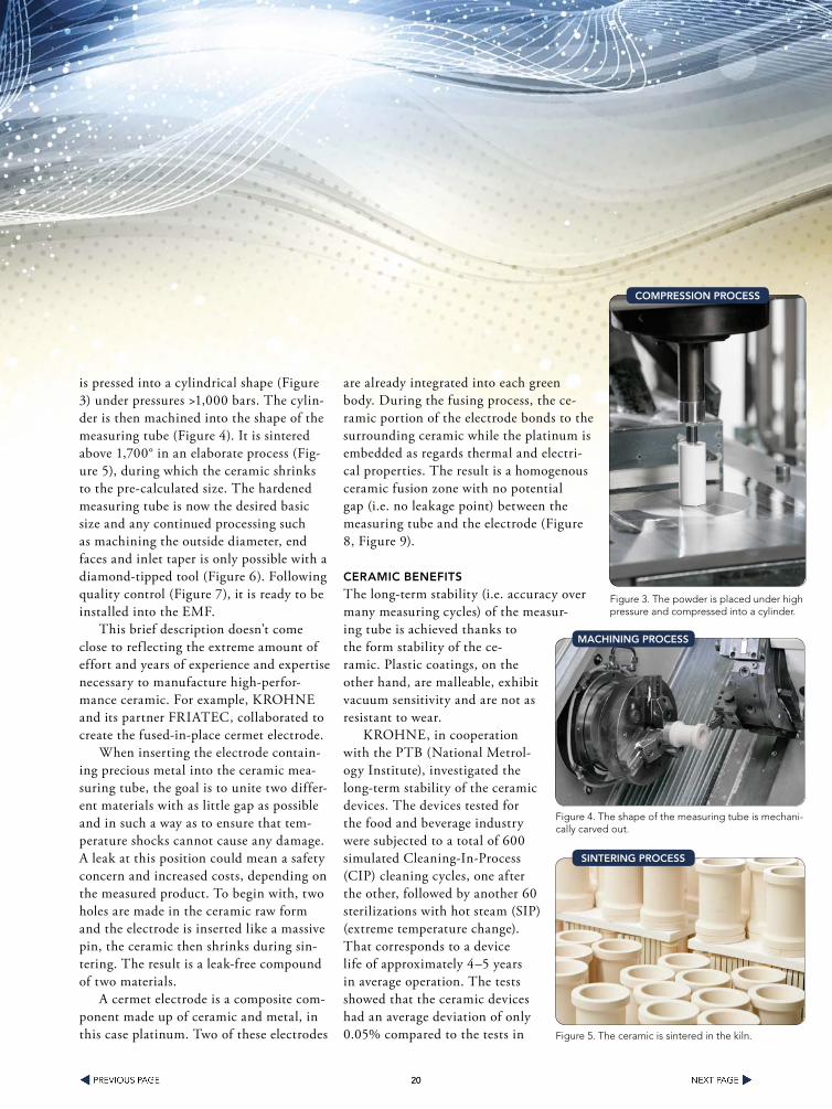
is pressed into a cylindrical shape (Figure 3) under pressures >1,000 bars. The cylin-der is then machined into the shape of the measuring tube (Figure 4). It is sintered above 1,700° in an elaborate process (Fig-ure 5), during which the ceramic shrinks to the pre-calculated size. The hardened measuring tube is now the desired basic size and any continued processing such as machining the outside diameter, end faces and inlet taper is only possible with a diamond-tipped tool (Figure 6). Following quality control (Figure 7), it is ready to be installed into the EMF.
This brief description doesn’t come close to ref lecting the extreme amount of effort and years of experience and expertise necessary to manufacture high-perfor-mance ceramic. For example, KROHNE and its partner FRIATEC, collaborated to create the fused-in-place cermet electrode.
When inserting the electrode contain-ing precious metal into the ceramic mea-suring tube, the goal is to unite two differ-ent materials with as little gap as possible and in such a way as to ensure that tem-perature shocks cannot cause any damage. A leak at this position could mean a safety concern and increased costs, depending on the measured product. To begin with, two holes are made in the ceramic raw form and the electrode is inserted like a massive pin, the ceramic then shrinks during sin-tering. The result is a leak-free compound of two materials.
A cermet electrode is a composite com-ponent made up of ceramic and metal, in this case platinum. Two of these electrodes
are already integrated into each green body. During the fusing process, the ce-ramic portion of the electrode bonds to the surrounding ceramic while the platinum is embedded as regards thermal and electri-cal properties. The result is a homogenous ceramic fusion zone with no potential gap (i.e. no leakage point) between the measuring tube and the electrode (Figure 8, Figure 9).
CERaMIC bEnEFITs
The long-term stability (i.e. accuracy over many measuring cycles) of the measur-ing tube is achieved thanks to the form stability of the ce-ramic. Plastic coatings, on the other hand, are malleable, exhibit vacuum sensitivity and are not as resistant to wear.
KROHNE, in cooperation with the PTB (National Metrol-ogy Institute), investigated the long-term stability of the ceramic devices. The devices tested for the food and beverage industry were subjected to a total of 600 simulated Cleaning-In-Process (CIP) cleaning cycles, one after the other, followed by another 60 sterilizations with hot steam (SIP) (extreme temperature change). That corresponds to a device life of approximately 4–5 years in average operation. The tests showed that the ceramic devices had an average deviation of only 0.05% compared to the tests in
Figure 3. The powder is placed under high pressure and compressed into a cylinder.
CoMPREssIon PRoCEss
Figure 4. The shape of the measuring tube is mechani-cally carved out.
MaCHInIng PRoCEss
Figure 5. The ceramic is sintered in the kiln.
sInTERIng PRoCEss

2121
new condition and also featured stable repeatability at various f low rates (Figure 10). The average deviation compared to the new condition was 8 times higher with measuring tubes with plastic liners.
High geometric stability is one of the reasons the OP-TIFLUX 5300 is often used as a reference device/Master-Meter in flow measurement plants in national institutions, measurement offices, nationally recognized testing bodies and notified bodies. Sterilization with hot steam (SIP) exceeds the temperature changes of over 100 K commonly found in processes in the chemical industry. Thanks to the adaptation of the thermal expansion properties of the measuring tube and cermet electrode, the material bond easily withstands this stress.
Burst tests proved that the measuring tubes with just 2mm wall thickness could withstand over 600 bar, and those with 4mm more than 1,000 bar internal pressure — a result of the consistent application of the finite element method (FEM). Checking the break lines after the break tests showed no specific nucleation site for the formation of cracks, neither near the fused-in-place electrodes nor in the rest of the measuring tube.
Additional material testing procedures included tensile and compression tests as well as corrosion tests. Tensile load tests showed strength close to the value of steel. The high compression strength is one of the properties of this ceramic. This helps ensure the measur-ing tubes are robust enough to withstand the mechanical loads placed on them during installation and operation in chemical plants.
An application example illustrates the abrasion resistance of the virtually diamond hard ceramic: the Dutch company NEDMAG Industries Mining and Manufacturing B.V. is Europe’s leading manufacturer of ultrapure synthetic magnesite (DBM: dead burned
Figure 6. A diamond-tipped tool is used to machine the outside diameter, end faces and inlet taper to complete the final finish-ing touches of the hardened measuring tube.
FInIsHIng TouCHEs
Figure 7. A helium leak test is performed to ensure quality control of the finished measuring tube.
qualITy ConTRol
Figure 8. In the electron microscope shot of fused-in-place cermet electrode (left), the light points (platinum) are the only way to recognize that there are two different materials.
uP ClosE

2222
magnesia). DBM is mainly used in fire-proof applications such as liners in blast furnaces. When producing DBM, magnesium hydroxide sludge with 53 % solid content also is created. To further process this extremely abrasive sludge, its flow rate must first be measured. Because a PFA or PTFE liner would fail in a short time in this case, the company opted to use an OP-TIFLUX 5300 with ceramic measuring tube (Figure 11).
To combat corrosion, the requirements of the chemical industry are extremely high. To equip standard processes and new production routes, KROHNE offers a comprehen-sive list of corrosion resistant EMF devices using ceramic measuring tubes.
To further increase process reliability, EMFs with ceramic measuring tubes are available in both sandwich (DN25…100) and flange versions (DN15…300). The flange version of the OPTIFLUX 5300 uses shorter screws (less expansion upon heating), to offer a high degree of fire resis-tance to ensure dangerous products don’t leak at connection points if a fire occurs. The flange version also features a Pressure Equipment Directive 97/23/EC with individual ap-proval for zirconium oxide (FRIALIT FZM) and has design approval for DN 15 to DN 300 from TÜV Rheinland. This enables the chemical operator to use a ceramic EMF per the Pressure Equipment Directive. This means the operator doesn’t have to run his own test and can reduce costs.
Electromagnetic f lowmeters with ceramic measur-ing tubes boast high performance, particularly in the chemical industry. Thanks to the unique combination of material properties such as surface hardness and finish, mechanical strength, resistance to corrosion and tem-perature change, the operator benefits from the extreme accuracy and long-term stability as well as vacuum and diffusion resistance. The chemical industry’s own re-quirements concerning process reliability, longevity and durability are well met.
RalF HauT is industry manager, chemistry at KROHNE. KROHNE is
a full-service provider for process measuring technology for the mea-
surement of flow, mass flow, level, pressure and temperature as well as
analytical tasks. For more infromation, visit www.us.krohne.com.
Figure 9. In this external shot of the finished ceramic measuring tube prior to installation into the EMF, the black dot represents the fused-in-place cermet electrode.
CERaMIC MEasuRIng TubE
Figure 10. Test series shows accuracy changes and average deviation from new condition.
TEsT REsulTs
Figure 11. The OPTIFLUX 5300 measures highly abrasive magnesium hydroxide sludge.
HEaVy DuTy aPPlICaTIons

2323
Solutions For Handling
DangerousChemicals
Safe
Award-winning Almatec® E-Series Plastic AODD pumps provide safe and reliable performance when handling the most dangerous acids, solvents and caustics.
• Solid block CNC machining
• Polyethylene and PTFE materials, conductive alsoavailable for explosion environments (ATEX)
• Ring design structure for improved product containment
• Optional features available (e.g. barrier chamber system) for further safety requirements
• Dry run ability, self-priming, gentle � uid handling, norotating parts, no shaft seals
Where Innovation Flows
World HeadquartersCarl-Friedrich-Gauß-Str. 547475 Kamp-Lintfort, GermanyO: +49/2842/961-0F: +49/2842/[email protected]
PSG Euro-Center™22069 Van Buren StreetGrand Terrace, CA 92313 USAO: +1 (909) [email protected]
14-ALMA-0236 Chemical Processing.indd 1 2/25/14 3:54 PM