fontaine fifth wheel no-slack...
TRANSCRIPT
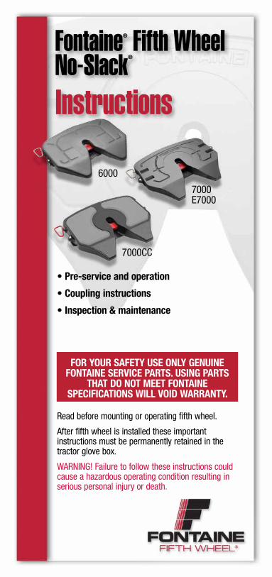
Fontaine® Fifth WheelNo-Slack®
Instructions
• Pre-service and operation
• Coupling instructions
• Inspection & maintenance
6000
7000E7000
7000CC
Read before mounting or operating fifth wheel.
After fifth wheel is installed these important instructions must be permanently retained in the tractor glove box.
WARNING! Failure to follow these instructions could cause a hazardous operating condition resulting in serious personal injury or death.
for your safety use only GenuIne fontaIne servICe Parts. usInG Parts
that do not meet fontaIne sPeCIfICatIons wIll voId warranty.
2
Introduction
WARNING! The visual inspection is required by law. Some improper couplings can pass a “tug test” and sound is not reliable to verify proper coupling. The coupling procedure is not complete without a visual inspection. It is necessary to get out of the tractor and look. Incorrect coupling could cause the trailer to disconnect, possibly resulting in serious personal injury or death.
WARNING! When coupling, the fifth wheel must lift the trailer. Always inflate the tractor suspension air bags prior to coupling. Coupling should not be attempted with the tractor suspension air bags deflated. Inflating the tractor suspension air bags while positioned underneath the trailer may result in damage to and incorrect coupling of the fifth wheel, possibly resulting in serious personal injury or death.
WARNING! Do not use any fifth wheel that has damaged components or fails to operate properly.
WARNING! Failure to follow these specifications will void the warranty and could affect product performance.
WARNING! Air cylinder(s) should not be disassembled as contents are under pressure.
WARNING! Under no circumstances should a sliding fifth wheel be repositioned while the tractor and trailer are in motion. This could result in personal injury or death.
WARNING! Do not use a lube plate (high-density polyethylene) on top of the fifth wheel or kingpin bolster plate in lieu of grease without prior approval by Fontaine.
warning!
3
Introductionhow to tell If the fIfth wheel Is ProPerly loCKed – no slack®
Verify secure coupling with a “tug test”, by easing the tractor forward, with the trailer brakes on, to feel resistance of the load. Set the parking brakes on the tractor and trailer and get out of the tractor and visually inspect, using a flashlight if necessary, that the fifth wheel is properly closed.
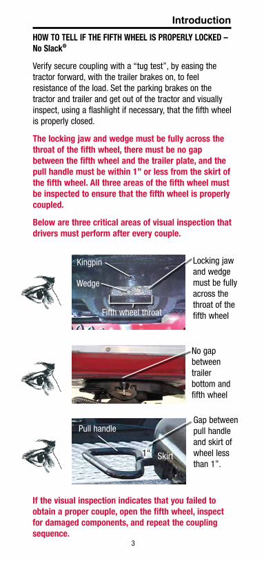
the locking jaw and wedge must be fully across the throat of the fifth wheel, there must be no gap between the fifth wheel and the trailer plate, and the pull handle must be within 1” or less from the skirt of the fifth wheel. all three areas of the fifth wheel must be inspected to ensure that the fifth wheel is properly coupled.
Below are three critical areas of visual inspection that drivers must perform after every couple.
If the visual inspection indicates that you failed to obtain a proper couple, open the fifth wheel, inspect for damaged components, and repeat the coupling sequence.
Locking jaw and wedge must be fully across the throat of the fifth wheel
Kingpin
Wedge
Fifth wheel throat
No gap between trailer bottom and fifth wheel
1" Skirt
Pull handleGap between pull handle and skirt of wheel less than 1”.
4
For over 60 years, Fontaine has been passing customer performance tests by building fifth wheels with innovative technology, uncompromising quality, and features designed to ensure cost-efficient performance.
This handbook provides instructions and recommended procedures to ensure optimum performance from your new Fontaine® No-Slack® fifth wheel.
Keep this handbook in the tractor glove box after your fifth wheel has been installed.
For convenience, record fifth wheel information below:
Model number: ________________________
Serial number: ________________________
In service date: ________________________
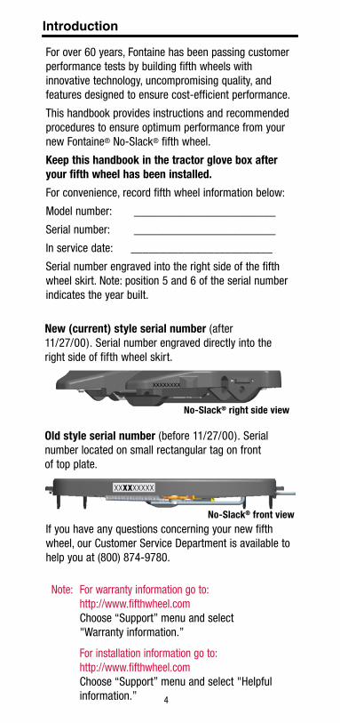
Serial number engraved into the right side of the fifth wheel skirt. Note: position 5 and 6 of the serial number indicates the year built.
If you have any questions concerning your new fifth wheel, our Customer Service Department is available to help you at (800) 874-9780.
Introduction
new (current) style serial number (after 11/27/00). Serial number engraved directly into the right side of fifth wheel skirt.
no-slack® right side view
old style serial number (before 11/27/00). Serial number located on small rectangular tag on front of top plate.
XXXXXXXXX
no-slack® front view
Note: For warranty information go to: http://www.fifthwheel.com
Choose “Support” menu and select "Warranty information.”
For installation information go to: http://www.fifthwheel.com
Choose “Support” menu and select "Helpful information.”
5
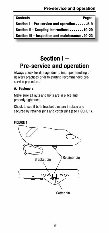
Contents Pages
Section I – Pre-service and operation . . . . . . 5-9
Section II – Coupling instructions . . . . . . . 10-20
Section III – Inspection and maintenance . 20-23
section I – Pre-service and operation
Always check for damage due to improper handling or delivery practices prior to starting recommended pre-service procedure.
a. fasteners
Make sure all nuts and bolts are in place and properly tightened.
Check to see if both bracket pins are in place and secured by retainer pins and cotter pins (see FIGURE 1).
Bracket pin Retainer pin
Cotter pin
Pre-service and operation
fIGure 1
6
B. lubrication
1. Tilt the top plate forward (front of the fifth wheel down) and apply grease to each bearing area through the zerk fitting (No-Slack® 6000/7000/7000CC/E7000 has two fittings each side) located on each side of the top plate just to the front of the bracket pins. Continue to apply grease until it is coming out of the back of the bearing. It may be necessary to raise the rear of the fifth wheel with a pry bar to open up the pocket slightly and allow the grease to flow through. A substantial amount of grease may be required initially to fill the reservoir. Tilt the wheel to the rear (rear of the wheel down) and repeat the procedure. Rock the top plate back and forth several times to spread the grease over the bearing surface. If you have a no lube bracket liner, do not grease.
Inspect the trailer kingpin plate and top surface of the fifth wheel to make sure each is properly greased. A liberal coating of grease should be applied to the complete surfaces of both the trailer kingpin plate and the top surface of the fifth wheel. A paddle or brush will make this job easier.
Do not use a lube plate (high density polyethylene) on top of the fifth wheel or on the kingpin in lieu of grease without prior approval by Fontaine Fifth Wheel. The additional thickness of this material can prevent the proper operation of the fifth wheel and can cause a dangerous condition.
2. Lubricate the fifth wheel prior to opening and closing. Referring to (see FIGURES 2-5 on next pages), grease the jaw and wedge on top and bottom. Separate the jaw and wedge with a large screwdriver and distribute the grease along the full length of the jaw and wedge mating surfaces. Open and close the fifth wheel several times to further distribute the grease.
Fontaine suggests the use of a Moly based lubricant such as Mobilgrease XHP320 or equivalent when applying lubricant to the locking jaw and wedge.
Lightly oil other moving parts in the fifth wheel. (Areas or regions that experience extreme and/or prolonged freezing temperatures should consider using a less viscous substance such as: 90-weight oil, diesel fuel, kerosene, motor oil, etc. Fontaine suggests contacting your specific
Pre-service and operation
7
lubricant manufacturer for guidelines on mixing compatibility of any lubricant). In cold weather applications please refer to technical bulletin TB-008. Technical bulletins are available at fifthwheel.com under support menu.
3. For sliding fifth wheels, lightly oil the locking mechanism. Operate the mechanism (air or manual) several times to ensure it is functioning properly.
4. Grease the top plate. Spread grease all over the mating surface of the top plate. Be sure the grease pockets built into the top plates are full of grease.
C. operation
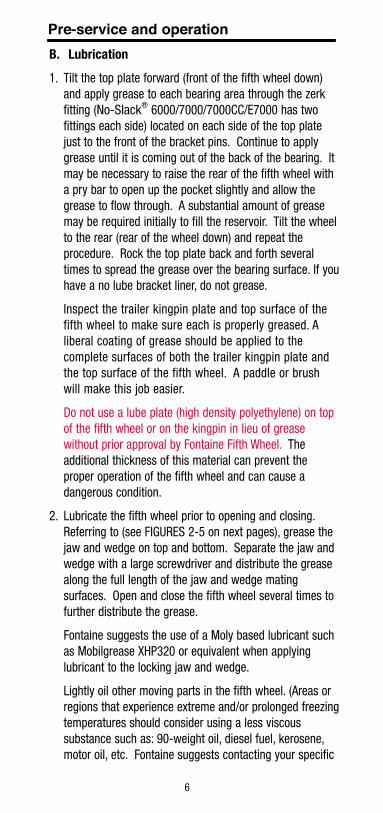
1. Fontaine’s No-Slack® 6000/7000/7000CC/E7000 & retractable handle fifth wheels shown in open by a straight pull on the release handle which releases the secondary lock automatically as the mechanism opens (see FIGURE 2 and 3).
Pre-service and operation
fIGure 2 – no-slack® 6000/7000/7000CC/e7000 Pull handle
A
A
fIGure 3 – no-slack® 6000/7000/7000CC/e7000
Retractable handle
8
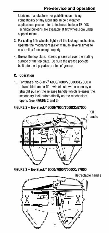
fIGure 4 – no-slack® 6000/7000/7000CC/e7000
Pre-service and operation2. Fontaine’s air actuated No-Slack® 6000/7000/
7000CC/E7000 air-actuated fifth wheel (see FIGURE 4) open with a release valve located on the dash or in a lock box mounted on the rear of the cab. To open, set the tractor parking brake and pull the release valve. Hold the valve open until the locking mechanism is locked in the open position. The pull valve will not activate the air cylinder unless the tractor parking brakes are set.
3. Close the locking mechanism using a test kingpin (Fontaine part number KIT-NOSLACK-KP). Repeat several times making sure that all moving parts have adequate lubrication.
4. The pull handle should always be free of grease or any substance which could prevent a firm grip, causing the handle to slip and resulting in injury.
fIGure 5
Separate jaw and wedge. Grease full length.
Jaw
Wedge
9
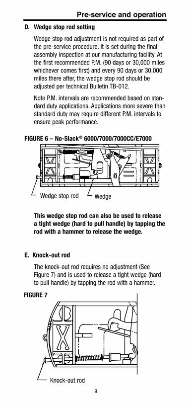
Pre-service and operationd. wedge stop rod setting
Wedge stop rod adjustment is not required as part of the pre-service procedure. It is set during the final assembly inspection at our manufacturing facility. At the first recommended P.M. (90 days or 30,000 miles whichever comes first) and every 90 days or 30,000 miles there after, the wedge stop rod should be adjusted per technical Bulletin TB-012.
Note P.M. intervals are recommended based on stan-dard duty applications. Applications more severe than standard duty may require different P.M. intervals to ensure peak performance.
this wedge stop rod can also be used to release a tight wedge (hard to pull handle) by tapping the rod with a hammer to release the wedge.
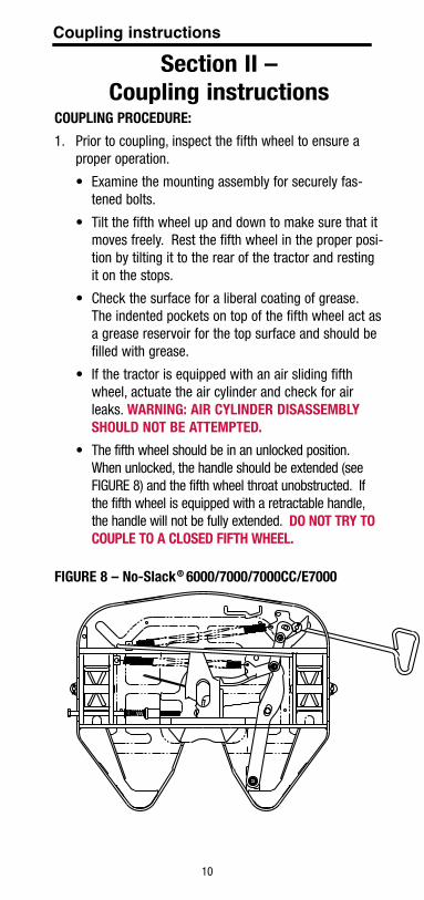
e. Knock-out rod
The knock-out rod requires no adjustment (See Figure 7) and is used to release a tight wedge (hard to pull handle) by tapping the rod with a hammer.
fIGure 6 – no-slack® 6000/7000/7000CC/e7000
WedgeWedge stop rod
fIGure 7
Knock-out rod
10
Coupling instructions
section II – Coupling instructions
CouPlInG ProCedure:
1. Prior to coupling, inspect the fifth wheel to ensure a proper operation.
• Examinethemountingassemblyforsecurelyfas-tened bolts.
• Tiltthefifthwheelupanddowntomakesurethatitmoves freely. Rest the fifth wheel in the proper posi-tion by tilting it to the rear of the tractor and resting it on the stops.
• Checkthesurfaceforaliberalcoatingofgrease.The indented pockets on top of the fifth wheel act as a grease reservoir for the top surface and should be filled with grease.
• Ifthetractorisequippedwithanairslidingfifthwheel, actuate the air cylinder and check for air leaks. warnInG: aIr CylInder dIsassemBly should not Be attemPted.
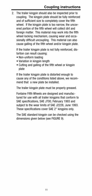
• The fifth wheel should be in an unlocked position. When unlocked, the handle should be extended (see FIGURE 8) and the fifth wheel throat unobstructed. If the fifth wheel is equipped with a retractable handle, the handle will not be fully extended. do not try to CouPle to a Closed fIfth wheel.
fIGure 8 – no-slack® 6000/7000/7000CC/e7000
11
2. The trailer kingpin should also be inspected prior to coupling. The kingpin plate should be fully reinforced and of sufficient size to completely cover the fifth wheel. If the kingpin plate is too narrow, the uncov-ered portion of the fifth wheel will collect dirt and foreign matter. This material may work into the fifth wheel locking mechanism, causing wear and occa-sionally difficult uncoupling. This material can also cause galling of the fifth wheel and/or kingpin plate.
If the trailer kingpin plate is not fully reinforced, dis-tortion can result causing:•Non-uniformloading•Variationinkingpinlength•Cuttingandgallingofthefifthwheelorkingpin
plate
If the trailer kingpin plate is distorted enough to cause any of the conditions listed above, we recom-mend that a new plate be installed.
The trailer kingpin plate must be properly greased.
Fontaine Fifth Wheels are designed and manufac-tured for use with all trailer kingpins that conform to SAE specifications, SAE J700, February 1993 and subject to the wear limits of SAE J2228, June 1993. These specifications cover SAE 2" kingpins only.
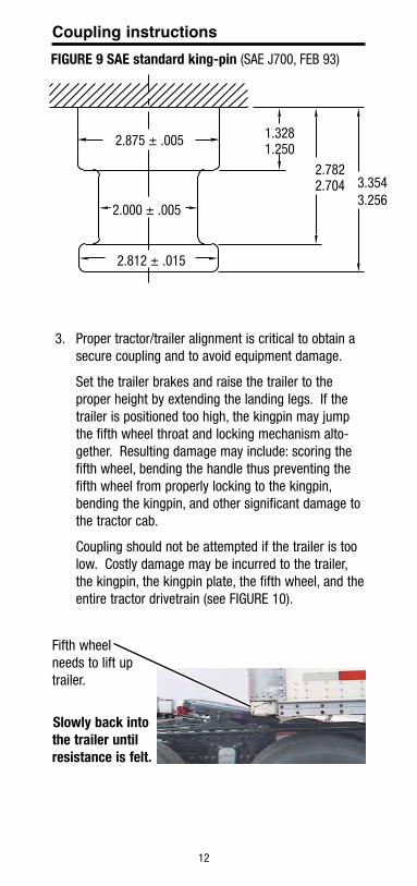
The SAE standard kingpin can be checked using the dimensions given below (see FIGURE 9).
Coupling instructions
12
Coupling instructions
3. Proper tractor/trailer alignment is critical to obtain a secure coupling and to avoid equipment damage.
Set the trailer brakes and raise the trailer to the proper height by extending the landing legs. If the trailer is positioned too high, the kingpin may jump the fifth wheel throat and locking mechanism alto-gether. Resulting damage may include: scoring the fifth wheel, bending the handle thus preventing the fifth wheel from properly locking to the kingpin, bending the kingpin, and other significant damage to the tractor cab.
Coupling should not be attempted if the trailer is too low. Costly damage may be incurred to the trailer, the kingpin, the kingpin plate, the fifth wheel, and the entire tractor drivetrain (see FIGURE 10).
Fifth wheel needs to lift up trailer.
slowly back into the trailer until resistance is felt.
fIGure 9 sae standard king-pin (SAE J700, FEB 93)
2.875 ± .005 1.3281.250
2.7822.704 3.354
3.256
2.812 ± .015
2.000 ± .005
13
Coupling instructions4. To couple the fifth wheel to the kingpin, be sure the
fifth wheel is positioned so that it tilts down at the rear and is resting on the stops.
Align the kingpin with the throat of the fifth wheel and ease the tractor toward the trailer. The trailer should strike the fifth wheel just at the top of the approach ramps. The fifth wheel will level with the kingpin plate and the kingpin should slide up the fifth wheel throat.
Coupling is complete when the fifth wheel locking mechanism snaps closed behind the kingpin.
Verify secure coupling with a "tug test," by easing the tractor forward, with trailer brakes on, to feel resistance of the load. If the coupling feels secure, visually inspect the fifth wheel. The jaw and wedge must be locked in place behind the kingpin, com-pletely across the throat of the fifth wheel, and the pull handle must be retracted and securely latched in the secondary lock.
14
Coupling instructions
warnInG! when coupling, the fifth wheel must lift the trailer. always inflate the tractor suspension air bags prior to coupling. Coupling should not be attempted with the tractor suspension air bags deflated.
Inflating the tractor suspension air bags while positioned underneath the trailer may result in damage to and incorrect coupling of the fifth wheel, possibly resulting in serious personal injury or death.
the visual inspection is required by law. some improper couplings can pass a “tug test” and sound is not reliable to verify proper coupling. the coupling procedure is not complete without a visual inspection. It is necessary to get out of the tractor and look. Incorrect coupling could cause the trailer to disconnect, possibly resulting in serious personal injury or death.
warning!
15
Coupling instructions
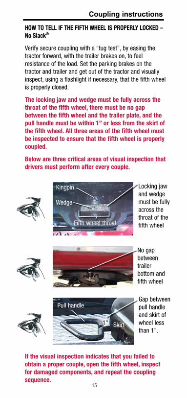
how to tell If the fIfth wheel Is ProPerly loCKed – no slack®
Verify secure coupling with a “tug test”, by easing the tractor forward, with the trailer brakes on, to feel resistance of the load. Set the parking brakes on the tractor and trailer and get out of the tractor and visually inspect, using a flashlight if necessary, that the fifth wheel is properly closed.
the locking jaw and wedge must be fully across the throat of the fifth wheel, there must be no gap between the fifth wheel and the trailer plate, and the pull handle must be within 1” or less from the skirt of the fifth wheel. all three areas of the fifth wheel must be inspected to ensure that the fifth wheel is properly coupled.
Below are three critical areas of visual inspection that drivers must perform after every couple.
If the visual inspection indicates that you failed to obtain a proper couple, open the fifth wheel, inspect for damaged components, and repeat the coupling sequence.
Locking jaw and wedge must be fully across the throat of the fifth wheel
Kingpin
Wedge
Fifth wheel throat
No gap between trailer bottom and fifth wheel
1" Skirt
Pull handleGap between pull handle and skirt of wheel less than 1”.
16
Coupling instructions
A
A
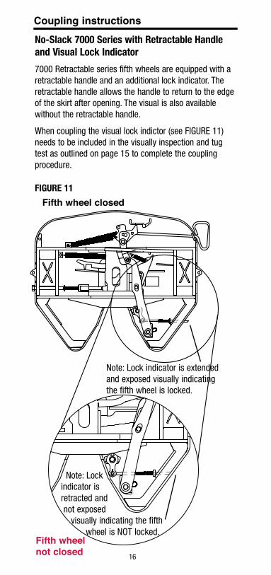
Fifth wheel closed
Fifth wheel not closed
fIGure 11
Note: Lock indicator is extended and exposed visually indicating the fifth wheel is locked.
Note: Lock indicator is retracted and not exposed visually indicating the fifth wheel is NOT locked.
no-slack 7000 series with retractable handle and visual lock Indicator
7000 Retractable series fifth wheels are equipped with a retractable handle and an additional lock indicator. The retractable handle allows the handle to return to the edge of the skirt after opening. The visual is also available without the retractable handle.
When coupling the visual lock indictor (see FIGURE 11) needs to be included in the visually inspection and tug test as outlined on page 15 to complete the coupling procedure.
17
Coupling instructions
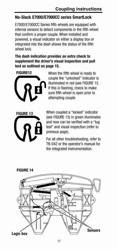
no-slack e7000/e7000CC series smartlock
E7000/E7000CC Series fifth wheels are equipped with internal sensors to detect components in the fifth wheel that confirm a proper couple. When installed and powered, a visual indicator on either a display box or integrated into the dash shows the status of the fifth wheel lock.
the dash indication provides an extra check to supplement the driver's visual inspection and pull test as outlined on page 15.
When the fifth wheel is ready to couple the “unlocked” indicator is illuminated in red (see FIGURE 12. If this is flashing, check to make sure fifth wheel is open prior to attempting couple.
When coupled a “locked” indicator (see FIGURE 13) in green illuminates and now can be verified with a “tug test” and visual inspection (refer to previous page).
For all other troubleshooting, refer to TB-042 or the operator’s manual for the integrated instrumentation.
logic boxsensors
fIGure12
fIGure 13
fIGure 14
18
slIde adJustment
under no circumstances should a sliding fifth wheel be repositioned while the tractor and trailer are in motion. this could result in serious personal injury or death.
do not attempt to slide the fifth wheel until all persons are clear of the vehicle.
note: the fifth wheel must be in the locked position when changing slide positions.
To position an air sliding fifth wheel:
1. Set the trailer brakes.
2. Unlock the cab control air valve and allow the air cylinder to retract the locking wedges.
3. Ease the tractor forward or backward to move the fifth wheel to the desired position.
4. Lock the air valve.
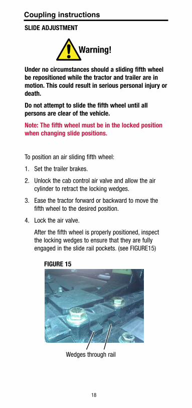
After the fifth wheel is properly positioned, inspect the locking wedges to ensure that they are fully engaged in the slide rail pockets. (see FIGURE15)
warning!
fIGure 15
Wedges through rail
Coupling instructions

19
unCouPlInG ProCedure:
1. Prior to uncoupling, set the trailer parking brakes. Back the tractor gently against the trailer. This will release the load on the fifth wheel locking mecha-nism.
If the truCK has an aIr susPensIon, do not dumP the aIr Before oPenInG the fIfth wheel. doInG so may Cause a hard to oPen sItuatIon.
2. Block the trailer wheels. If poor ground conditions exist you may have to provide a base for the trailer landing gear.
3. Lower landing gear until it contacts the ground. Give extra turns to reduce load on fifth wheel. do not raIse traIler off of the fIfth wheel.
4. Disconnect air lines and open the fifth wheel.
5. Slowly drive tractor from under trailer.
Coupling instructions
section III – Inspection and maintenance
procedureswarnInG! do not use any fifth wheel that has damaged components or fails to operate properly.
Fontaine recommends that preventative maintenance be performed after 90 days or 30,000 miles, whichever comes first and every 90 days or 30,000 miles thereafter.
Note: P.M. intervals are recommended based on standard duty applications. Applications more severe than standard duty may require different P.M. intervals to ensure peak performance.
Using a suitable solvent, degrease the fifth wheel and mounting brackets and inspect for:
1. Cracks in the fifth wheel assembly, mounting brackets, and mounting parts.
2. Wear and/or damage to moving parts.
3. Loose nuts and bolts in the fifth wheel and in the mounting hardware.
20
Inspection and maintenance procedures4. Securely fastened and properly working springs.
5. Check to see if both bracket pins are in place and secured by retainer pins and cotter pins.
6. Free front to rear rock on brackets with greaseless lin-ers. If the fifth wheel does not rock freely, remove the top plate and inspect the bracket liners. Replace liners that are broken or have worn excessively. Check the bracket liner thickness at every scheduled maintenance. Replace liners if the thickness is less than .125" at the top of the liners.
7. Proper operation of the slide locking mechanism. Check for air leaks in the cylinder and supply line.
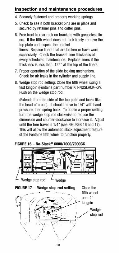
8. Wedge stop rod setting: Close the fifth wheel using a test kingpin (Fontaine part number KIT-NOSLACK-KP). Push on the wedge stop rod.
(Extends from the side of the top plate and looks like the head of a bolt). It should move in 1/4" with hand pressure, then spring back. To obtain a proper setting, turn the wedge stop rod clockwise to reduce the dimension and counter-clockwise to increase it. Adjust until the free travel is 1/4" (see FIGURES 16 and 17). This will allow the automatic slack adjustment feature of the Fontaine fifth wheel to function properly.
fIGure 16 – no-slack® 6000/7000/7000CC
WedgeWedge stop rod
fIGure 17 – wedge stop rod setting
Wedge stop rod
Close the fifth wheel on a 2" kingpin
21
Inspection and maintenance procedureslubrication
Follow the instructions provided in the Pre-Service Procedure on pages 5-9.
Periodically remove the fifth wheel to clean old grease from the bracket grease channels to help insure an even grease distribution of fresh grease.
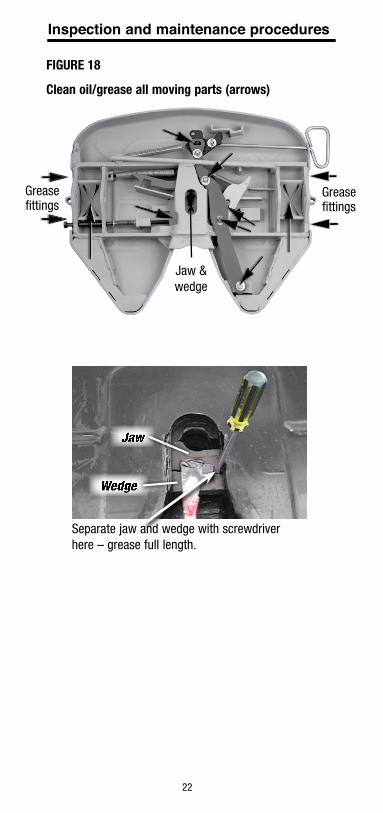
Special precautions should be taken during cold weather to ensure that the Fontaine No-Slack® locking mechanisms operate freely. Ice and sludge can build up and lubricants become thick and binding at low temperatures. When the temperature drops below freezing, Fontaine recommends a thorough cleaning of the latching mechanism using a suitable cleaner or degreaser to make sure that all moving parts operate freely. Lubricate the fifth wheel prior to opening and closing (see FIGURE 18 on next page). Grease the jaw and wedge on top and bottom. Separate the jaw and wedge with a large screwdriver and distribute the grease along the full length of the jaw and wedge mating surfaces. Open and close the fifth wheel several times to further distribute the grease.
fontaine suggests the use of a moly based lubricant such as mobilgrease XhP320 or equivalent when applying lubricant. (areas or regions that experience extreme and/or prolonged freezing temperatures should consider using a less viscous substance such as: 90-weight oil, diesel fuel, kerosene, motor oil, etc. doing so will help ensure proper movement/lubrication of the latching mechanism. fontaine suggests contacting your specific lubricant manufacturer for guidelines on coldmixing compatibility of any lubricant. In cold weather applications please refer to technical bulletin tB-008. technical bulletins are available at fifthwheel.com under support menu).
The regular performance of the routine, "90-Day/ 30,000 Mile Preventative Maintenance Procedure," is also recommended.
22
Jaw & wedge
Grease fittings
Grease fittings
Separate jaw and wedge with screwdriver here – grease full length.
Clean oil/grease all moving parts (arrows)
fIGure 18
Inspection and maintenance procedures
Jaw
Wedge

23
for sales and service locations,
additional copies of this handbook, or
installation instructions (lt-181) go to
www.fifthwheel.com or contact fontaine
Customer support at 1-800-874-9780.
©2012FontaineFifthWheel•LT-001•February2015All specifications are subject to change without notice.
Fontaine Fifth Wheel 7574CommerceCircle•Trussville,AL35173USA
800.874.9780•Fax205.655.9982 www.fifthwheel.com