food plot seeder nual a m s operator
TRANSCRIPT

OP
ER
AT
OR
'S M
AN
UA
LFOOD PLOT SEEDERM
AN10
74(R
ev. 7
/24/
2019
)
FPS48FPS60FPS72FPS84

2 Introduction Gen’l (Rev. 2/25/2016)
TO THE DEALER:Assembly and proper installation of this product is the responsibility of the Woods® dealer. Read manual instructionsand safety rules. Make sure all items on the Dealer’s Pre-Delivery and Delivery Check Lists in the Operator’s Manualare completed before releasing equipment to the owner.The dealer must complete the online Product Registration form at the Woods Dealer Website which certifies thatall Dealer Check List items have been completed. Dealers can register all Woods product atdealer.WoodsEquipment.com under Product Registration.Failure to register the product does not diminish customer’s warranty rights.
TO THE OWNER:Read this manual before operating your Woods equipment. The information presented will prepare you to do a better andsafer job. Keep this manual handy for ready reference. Require all operators to read this manual carefully and becomeacquainted with all adjustment and operating procedures before attempting to operate. Replacement manuals can beobtained from your dealer. To locate your nearest dealer, check the Dealer Locator at www.WoodsEquipment.com, or inthe United States and Canada call 1-800-319-6637.The equipment you have purchased has been carefully engineered and manufactured to provide dependable andsatisfactory use. Like all mechanical products, it will require cleaning and upkeep. Lubricate the unit as specified.Observe all safety information in this manual and safety decals on the equipment.For service, your authorized Woods dealer has trained mechanics, genuine Woods service parts, and the necessarytools and equipment to handle all your needs.Use only genuine Woods service parts. Substitute parts will void the warranty and may not meet standards required forsafe and satisfactory operation. Record the model number and serial number of your equipment in the spacesprovided:
Model: _______________________________ Date of Purchase: _____________________
Serial Number: (see Safety Decal section for location) ____________________________________Provide this information to your dealer to obtain correct repair parts.Throughout this manual, the term NOTICE is used to indicate that failure to observe can cause damage to equipment.The terms CAUTION, WARNING, and DANGER are used in conjunction with the Safety-Alert Symbol (a triangle withan exclamation mark) to indicate the degree of hazard for items of personal safety.

Introduction 3MAN1074 (9/15/2014)
TABLE OF CONTENTS
INTRODUCTION . . . . . . . . . . . . . . . . . . . . . . . . . . . . . . . . . . . . . . . . . . . . . . . . . . . . . . . . . . . . . . . . . 2SPECIFICATIONS . . . . . . . . . . . . . . . . . . . . . . . . . . . . . . . . . . . . . . . . . . . . . . . . . . . . . . . . 4GENERAL INFORMATION. . . . . . . . . . . . . . . . . . . . . . . . . . . . . . . . . . . . . . . . . . . . . . . . . . 4
SAFETY . . . . . . . . . . . . . . . . . . . . . . . . . . . . . . . . . . . . . . . . . . . . . . . . . . . . . . . . . . . . . . . . . . . . . . . 5SAFETY RULES. . . . . . . . . . . . . . . . . . . . . . . . . . . . . . . . . . . . . . . . . . . . . . . . . . . . . . . . . . 5
TRAINING . . . . . . . . . . . . . . . . . . . . . . . . . . . . . . . . . . . . . . . . . . . . . . . . . . . 5PREPARATION . . . . . . . . . . . . . . . . . . . . . . . . . . . . . . . . . . . . . . . . . . . . . . . 5OPERATION . . . . . . . . . . . . . . . . . . . . . . . . . . . . . . . . . . . . . . . . . . . . . . . . . 5TRANSPORTATION . . . . . . . . . . . . . . . . . . . . . . . . . . . . . . . . . . . . . . . . . . . 6MAINTENANCE. . . . . . . . . . . . . . . . . . . . . . . . . . . . . . . . . . . . . . . . . . . . . . . 6STORAGE . . . . . . . . . . . . . . . . . . . . . . . . . . . . . . . . . . . . . . . . . . . . . . . . . . . 6
SAFETY & INSTRUCTIONAL DECALS . . . . . . . . . . . . . . . . . . . . . . . . . . . . . . . . . . . . . . . . 7OPERATION . . . . . . . . . . . . . . . . . . . . . . . . . . . . . . . . . . . . . . . . . . . . . . . . . . . . . . . . . . . . . . . . . . . . 9
OPERATION. . . . . . . . . . . . . . . . . . . . . . . . . . . . . . . . . . . . . . . . . . . . . . . . . . . . . . . . . . . . . 9SEEDER GROUND TOOL OPERATION . . . . . . . . . . . . . . . . . . . . . . . . . . . 9ATTACHING SEEDER TO TRACTOR. . . . . . . . . . . . . . . . . . . . . . . . . . . . . 10SEEDING OPERATION. . . . . . . . . . . . . . . . . . . . . . . . . . . . . . . . . . . . . . . . 11SEED RATE CHARTS. . . . . . . . . . . . . . . . . . . . . . . . . . . . . . . . . . . . . . . . . 13CALIBRATION FORMULA. . . . . . . . . . . . . . . . . . . . . . . . . . . . . . . . . . . . . . 18PRE-OPERATION CHECKLIST . . . . . . . . . . . . . . . . . . . . . . . . . . . . . . . . . 18
OWNER SERVICE . . . . . . . . . . . . . . . . . . . . . . . . . . . . . . . . . . . . . . . . . . . . . . . . . . . . . . . . . . . . . . 19OWNER SERVICE . . . . . . . . . . . . . . . . . . . . . . . . . . . . . . . . . . . . . . . . . . . . . . . . . . . . . . . 19
LUBRICATION INFORMATION. . . . . . . . . . . . . . . . . . . . . . . . . . . . . . . . . . 19CLEANING . . . . . . . . . . . . . . . . . . . . . . . . . . . . . . . . . . . . . . . . . . . . . . . . . 20
ASSEMBLY . . . . . . . . . . . . . . . . . . . . . . . . . . . . . . . . . . . . . . . . . . . . . . . . . . . . . . . . . . . . . . . . . . . . 21ASSEMBLY . . . . . . . . . . . . . . . . . . . . . . . . . . . . . . . . . . . . . . . . . . . . . . . . . . . . . . . . . . . . 21
DEALER SET-UP INSTRUCTIONS . . . . . . . . . . . . . . . . . . . . . . . . . . . . . . 21OPTIONAL ACCESSORIES . . . . . . . . . . . . . . . . . . . . . . . . . . . . . . . . . . . . 21DEALER CHECK LISTS . . . . . . . . . . . . . . . . . . . . . . . . . . . . . . . . . . . . . . . 22
PARTS INDEX. . . . . . . . . . . . . . . . . . . . . . . . . . . . . . . . . . . . . . . . . . . . . . . . . . . . . . . . . . . . . . . . . . 23APPENDIX . . . . . . . . . . . . . . . . . . . . . . . . . . . . . . . . . . . . . . . . . . . . . . . . . . . . . . . . . . . . . . . . . . . . 40
BOLT TORQUE CHART. . . . . . . . . . . . . . . . . . . . . . . . . . . . . . . . . . . . . . . . . . . . . . . . . . . 40BOLT SIZE CHART & ABBREVIATIONS . . . . . . . . . . . . . . . . . . . . . . . . . . . . . . . . . . . . . . 41
INDEX . . . . . . . . . . . . . . . . . . . . . . . . . . . . . . . . . . . . . . . . . . . . . . . . . . . . . . . . . . . . . . . . . . . . . . . . 42REPAIR PARTS WARRANTY. . . . . . . . . . . . . . . . . . . . . . . . . . . . . . . . . . . . . . . . . . . . . . . . . . . . . . 43PRODUCT WARRANTY . . . . . . . . . . . . . . . . . . . . . . . . . . . . . . . . . . . . . . . . . . . . . . . . . . . . . . . . . . 44
Si no lee Ingles, pida ayuda a alguien que si lo lee para que le
traduzca las medidas de seguridad.
LEA EL INSTRUCTIVO!!

4 Introduction MAN1074 (9/15/2014)
SPECIFICATIONS
GENERAL INFORMATIONThe purpose of this manual is to assist you in operatingand maintaining your Food Plot Seeder. Read it care-fully. It furnishes information and instructions that willhelp you achieve years of dependable performance.These instructions have been compiled from extensivefield experience and engineering data. Some informa-tion may be general in nature due to unknown andvarying operating conditions. However, through experi-ence and these instructions, you should be able todevelop procedures suitable to your particular situa-tion.
The illustrations and data used in this manual were cur-rent at the time of printing but, due to possible inlineproduction changes, your machine may vary slightly indetail. We reserve the right to redesign and change themachines as may be necessary without notification.
■ Food Plot Seeder should never be operatedwith any safety shielding removed.
Throughout this manual, references are made to rightand left direction. These are determined by standingbehind the equipment facing the direction of forwardtravel.
FPS48 FPS60 FPS72 FPS84
Working Width 49.25" 60" 72" 84"Overall Width (Nylon Cultipacker) 60.75" 71.50" 83.50" 95.50"Cultipacker Diameter (Front and Rear) 11" 11" 11" 11"Front Disc Angle 0°,8°,12°,17°,23° 0°,6°,10°,14°,18° 0°,5°,8°,12°,15° 0°,4°,6°,9°,13°Disc Diameter 16" notched 16" notched 18" notched 18" notchedDisc Spacing 7.5" 7.5" 7.5" 7.5"Hitch Cat I, II Cat I, II Cat I, II Cat I, IIQuick Hitch compatible Y Y Y YTractor HP Requirement 25-45 hp 30-65 hp 35-85 hp 40-125 hpBase Unit (Lightest) Weight - Disc, Primary Box, Row Unit, Spiked Drive Roller
836 lbs. 904 lbs. 1191 lbs. 1310 lbs.
Fully Configured (Heaviest) Weight - Disc, Primary Box, Two Legume Boxes, Row Unit, Cast Iron Cultipacker, Scrapers, Culti-packer Drive Roller
1268 lbs. 1423 lbs. 1824 lbs. 2051 lbs.
Primary Seedbox Capacity (bu) 4 5 6 7Legume Seedbox Capacity (bu) 1 1.25 1.5 1.75Seedcups/Picker wheels 7 8 10 12Primary Seed Distribution Method Row Row Row RowLegume Seed Distribution Method Broadcast drop
with wind deflec-tor tray
Broadcast drop with wind deflec-tor tray
Broadcast drop with wind deflector tray
Broadcast drop with wind deflector tray
�������
(Rev. 12/07/2018)

Safety 5PSS48-72 Safety Rules (11/5/2012)
TRAINING Safety instructions are important! Read allattachment and power unit manuals; follow allsafety rules and safety decal information. (Replace-ment manuals and safety decals are available fromyour dealer. To locate your nearest dealer, checkthe Dealer Locator at www.WoodsEquipment.com,or in the United States and Canada call 1-800-319-6637.) Failure to follow instructions or safety rulescan result in serious injury or death. If you do not understand any part of this manualand need assistance, see your dealer. Know your controls and how to stop engine andattachment quickly in an emergency. Operators must be instructed in and be capableof the safe operation of the equipment, its attach-ments, and all controls. Do not allow anyone tooperate this equipment without proper instructions. Never allow children or untrained persons tooperate equipment.
PREPARATION Check that all hardware is properly installed.Always tighten to torque chart specificationsunless instructed otherwise in this manual. Always wear relatively tight and belted clothingto avoid getting caught in moving parts. Wearsturdy, rough-soled work shoes and protectiveequipment for eyes, hair, hands, hearing, and head;and respirator or filter mask where appropriate. Make sure attachment is properly secured,adjusted, and in good operating condition. Make sure all safety decals are installed.Replace if damaged. (See Safety Decals section forlocation.)
A minimum 20% of tractor and equipmentweight must be on the tractor front wheels whenattachments are in transport position. Without thisweight, front tractor wheels could raise up result-ing in loss of steering. The weight may be attainedwith front wheel weights, ballast in tires, front trac-tor weights or front loader. Weigh the tractor andequipment. Do not estimate.
OPERATION
Keep bystanders away from equipment.
Do not operate or transport equipment whileunder the influence of alcohol or drugs.
Install Lighting Kit 604387 when this equipmentobscures the tractor’s tail lamps or stop lamps.
Operate only in daylight or good artificial light.
Keep hands, feet, hair, and clothing away fromequipment while engine is running. Stay clear of allmoving parts.
Always comply with all state and local lightingand marking requirements.
Never allow riders on power unit or attachment.
Power unit must be equipped with ROPS orROPS cab and seat belt. Keep seat belt securelyfastened. Falling off power unit can result in deathfrom being run over or crushed. Keep foldableROPS system in “locked up” position at all times.
Always sit in power unit seat when operatingcontrols or starting engine. Securely fasten seatbelt, place transmission in neutral, engage brake,and ensure all other controls are disengagedbefore starting power unit engine.
Look down and to the rear and make sure areais clear before traveling in reverse.
Do not operate seeder in reverse.
Use extreme care when working close to fences,ditches, other obstructions, or on hillsides.
Do not operate or transport on steep slopes.
Do not stop, start, or change directions sud-denly on slopes.
Use extreme care and reduce ground speed onslopes and rough terrain.
(Safety Rules continued on next page)
Safety is a primary concern in the design andmanufacture of our products. Unfortunately, ourefforts to provide safe equipment can be wipedout by an operator’s single careless act.In addition to the design and configuration ofequipment, hazard control and accident preven-tion are dependent upon the awareness, con-cern, judgement, and proper training ofpersonnel involved in the operation, transport,maintenance, and storage of equipment.It has been said, “The best safety device is aninformed, careful operator.” We ask you to bethat kind of operator.
SAFETY RULESATTENTION! BECOME ALERT! YOUR SAFETY IS INVOLVED!
(Rev. 4/24/2018)

6 Safety PSS48-72 Safety Rules (11/5/2012)
(Safety Rules continued from previous page)
Watch for hidden hazards on the terrain duringoperation.
Stop power unit and equipment immediatelyupon striking an obstruction. Turn off engine,remove key, inspect, and repair any damage beforeresuming operation.
TRANSPORTATION Use additional caution and reduce speed whenunder adverse surface conditions, turning, or oninclines.
A minimum 20% of tractor and equipmentweight must be on the tractor front wheels whenattachments are in transport position. Without thisweight, front tractor wheels could raise up result-ing in loss of steering. The weight may be attainedwith front wheel weights, ballast in tires, front trac-tor weights or front loader. Weigh the tractor andequipment. Do not estimate.
Do not operate or transport on steep slopes.
Do not operate or transport equipment whileunder the influence of alcohol or drugs.
Always comply with all state and local lightingand marking requirements.
Never allow riders on power unit or attachment.
Install Lighting Kit 604387 when this equipmentobscures the tractor’s tail lamps or stop lamps.
Always raise unit and install transport lockbefore transporting. Leak down or failure ofmechanical or hydraulic system can cause equip-ment to drop.
Always attach safety chain to tractor drawbarwhen transporting unit.
Never exceed 25 mph (40.2 km/h) during trans-port.
MAINTENANCE Before dismounting power unit or performingany service or maintenance, follow these steps:
disengage power to equipment, lower the 3-pointhitch and all raised components to the ground,operate valve levers to release any hydraulic pres-sure, set parking brake, stop engine, remove key,and unfasten seat belt.
NEVER GO UNDERNEATH EQUIPMENT. Neverplace any part of the body underneath equipmentor between moveable parts even when the enginehas been turned off. Hydraulic system leak-down,hydraulic system failures, mechanical failures, ormovement of control levers can cause equipmentto drop or rotate unexpectedly and cause severeinjury or death.
• Service work does not require going under-neath.• Read Operator's Manual for service instruc-tions or have service performed by a qualifieddealer.
Always wear relatively tight and belted clothingto avoid getting caught in moving parts. Wearsturdy, rough-soled work shoes and protectiveequipment for eyes, hair, hands, hearing, and head;and respirator or filter mask where appropriate.
Make sure attachment is properly secured,adjusted, and in good operating condition.
Keep all persons away from operator controlarea while performing adjustments, service, ormaintenance.
Tighten all bolts, nuts, and screws to torquechart specifications. Check that all cotter pins areinstalled securely to ensure equipment is in a safecondition before putting unit into service.
Make sure all safety decals are installed.Replace if damaged. (See Safety Decals section forlocation.)
STORAGE
Block equipment securely for storage.
Keep children and bystanders away from stor-age area.
SAFETY RULESATTENTION! BECOME ALERT! YOUR SAFETY IS INVOLVED!
(Rev. 7/12/2019)

Safety 7MAN1074 (9/15/2014)
4 - PN 15502
(Safety Decals continued on next page)
5 - PN 18868 7 - Serial Number Plate
11 - PN 20106 Red Reflector
8 - PN 1034504 9 - PN 1041910
6 - PN 24611 Slow Moving Vehicle
10 - PN W5669
2 x 4.5 (48 & 60 Seeders) PN 57123 Red Reflector 2 x 9 (72 & 84 Seeders)
BE CAREFUL!Use a clean, damp cloth to clean safety decals.Avoid spraying too close to decals when using apressure washer; high-pressure water can enterthrough very small scratches or under edges ofdecals causing them to peel or come off.
Replacement safety decals can be ordered free fromyour Woods dealer. To locate your nearest dealer,check the Dealer Locator atwww.WoodsEquipment.com, or in the United Statesand Canada call 1-800-319-6637.
SAFETY & INSTRUCTIONAL DECALSATTENTION! BECOME ALERT! YOUR SAFETY IS INVOLVED!
Replace Immediately If Damaged!
Rev. (7/24/2019)

8 Safety MAN1074 (9/15/2014)
SAFETY & INSTRUCTIONAL DECALSATTENTION! BECOME ALERT! YOUR SAFETY IS INVOLVED!
Replace Immediately If Damaged!
3 - PN 55122
1 - PN 55121
2 - PN 1003751
WARNING
55121--C
FALLING OFF CAN RESULT IN BEING RUN OVER. Tractor must be equipped with ROPS (or ROPS CAB) and
seat belt. Keep foldable ROPS systems in “locked up”position at all times.
Buckle Up! Keep seat belt securely fastened. Allow no riders.
RAISED IMPLEMENT CAN DROP AND CRUSH. Never go underneath raised implement which can drop
from equipment or tractor 3-point hitch hydraulic leakdown, hydraulic system failures, movement of controllevers or mechanical linkage failures.
Service work does not require going underneathimplement. Read manual instructions.
FALLING OFF OR GOING UNDERNEATH IMPLEMENTCAN RESULT IN SERIOUS INJURY OR DEATH.
CRUSHING AND PINCHING HAZARD� Be extremely careful handling various parts of
the machine. They are heavy and hands, fingers, feet, and other body parts could be crushed or pinched between tractor and implement.
� Operate tractor controls from tractor seat only. � Do not stand between tractor and implement
when tractor is in gear. � Make sure parking brake is engaged before
going between tractor and implement.� Stand clear of machine while in operation or
when it is being raised or lowered. FAILURE TO FOLLOW THESE
INSTRUCTIONS COULD RESULT IN SERIOUS INJURY OR DEATH.
WARNING
1003751-A
(Safety Decals continued from previous page)

Operation 9MAN1074 (9/15/2014)
OPERATIONThe operator is responsible for the safe operation ofthis seeder. The operator must be properly trained.Operators should be familiar with the equipment, thetractor, and all safety practices before starting opera-tion. Read the safety rules and safety decals on page 5through page 8.
Recommended tractor ground speed is from 2 to 5mph.
Power unit must be equipped with Roll OverProtection System (ROPS) or ROPS cab and seatbelt. Keep seat belt securely fastened. Falling offpower unit can result in death from being run overor crushed. Keep foldable ROPS system in “lockedup” position at all times.
Never allow children or untrained persons tooperate equipment.
Keep bystanders away from equipment.
Keep hands, feet, hair, and clothing away fromequipment while engine is running. Stay clear of allmoving parts.
Stop power unit and equipment immediatelyupon striking an obstruction. Turn off engine, setparking brake, remove key, inspect, and repair anydamage before resuming operation.
Always wear relatively tight and belted clothingto avoid getting caught in moving parts. Wearsturdy, rough-soled work shoes and protectiveequipment for eyes, hair, hands, hearing, and head;and respirator or filter mask where appropriate.
SEEDER GROUND TOOL OPERATION
The Food Plot Seeder is an excellent primary seeder,food plot and conservation seeder. It is equipped with adisc tool, cultipacker or spiked drive roller and trailingcultipacker. The seed boxes can be disengaged so thatthe ground tools can prepare the optimal seed bed withmultiple passes, if necessary. The front disc tool can beused to overturn weeds, loosen soil, mix dry and moistsoils, and incorporate pre-applied fertilizer to theground. The cultipacker levels the soil, helps dispersethe seed when broadcast planting, creates seed to soilcontact and creates ridges/valleys for moisture reten-
tion. The spiked roller aerates the soil, creates pocketsfor moisture, and places seed on the seedbed withseed/soil contact.
Front Disc
The front disc tool can prepare a seedbed without prioruse of a separate disc or tillage tool. When the discsare straight, the seeder creates little soil disturbance.When the discs are angled fully backward, the seedercreates maximum soil disturbance and the seedbedcan usually be prepared in one or two passes. The dischas four angled positions to provide an array of soilpenetration depths and seedbed preparation.
Figure 1. Disc in Straight Position (mast plates hidden for picture clarity) (72" Seeder Shown)
Figure 2. Disc in Angled Position (mast plates hidden for picture clarity) (72" Seeder Shown)
�������
CAUTION

10 Operation MAN1074 (9/15/2014)
Chain Drive DisconnectThe Food Plot Seeder seed boxes can be engaged ordisengaged so that any one seed box or all seed boxescan be operative or inoperative. See Figure 3 and Fig-ure 19 for disconnect locations. It is not recommendedto run the plastic seed cup assemblies without seedbeing metered.
It may be necessary to make several passes with theground engaging tools before planting seed. Disengag-ing the seed box chain drive will allow the soil bed to beprepared without planting seed or running the plasticseed cup assemblies in a dry state.
Figure 3. Chain Drive Disconnect
Drive RollerThe Food Plot Seeder comes with either a spiked orcultipacker drive roller.
The spiked tooth roller aerates the soil, creates pocketsfor moisture and places seed in the seedbed withseed/soil contact.
The drive cultipacker firms and presses soil kicked upby the front disc blades. This creates a uniform seed-bed with the soil firmed for ensuring proper seed germi-nation. See Figure 10.
OperationThe power for operating the seeder comes from con-tact between the seeder drive roller and the ground.
IMPORTANT■ Do not operate seeder in reverse. Operatingseeder in reverse may result in damage to seedboxes and chain drive system.
Know how to stop the tractor and seeder quickly in anemergency.
Survey the area to be worked and remove any obstruc-tions that may affect the performance of the equipment.
Tractor Stability
A minimum 20% of tractor and equipmentweight must be on the tractor front wheels whenattachments are in transport position. Without thisweight, front tractor wheels could raise up result-ing in loss of steering. The weight may be attainedwith front wheel weights, ballast in tires, front trac-tor weights or front loader. Weigh the tractor andequipment. Do not estimate.
Figure 4. Tractor Stability
ATTACHING SEEDER TO TRACTORNOTE: The Food Plot Seeder is designed for use onCategory I and II, 3-point hitch tractors. See page 4 forspecifications.
1. Attach the tractor’s lower lift arms to the seederand secure with mounting pins and klik pins. SeeFigure 5 and Figure 6.
2. Attach the tractor’s top link to the mast plates of theseeder. For controlled depth of tillage, use thefixed-pin location above the quick hitch bushing.See Figure 5 and Figure 6.
3. To enable the seeder to follow the contours ofuneven ground, install the tractor’s top link in thelong slot in the top of the mast plates. For properfloat (up and down) the top link pin should becentered in the slot (recommended for beginners).
4. For quick hitch use, install the available quick hitchbushings. The seeder will not float with a quickhitch installed.
5. Adjust the lower lift arm anti-sway device toprevent excessive side-to-side movement of theseeder.
NOTE: The seeder can be operated in a float or fixed3-point hitch position. For beginning usage, the floatposition is recommended. See Figure 5.
NOTE: An optional quick hitch bushing kit, P/N1038791 is available.NOTE: When using CAT II hitch fixed top link hole,remove quick hitch bushing to prevent tractor top linkfrom bending.
Disengaged Engaged DP19
�������
(Rev. 4/25/2018)

Operation 11MAN1074 (9/15/2014)
Figure 5. Hitch
Figure 6. Quick Hitch - CAT I and CAT II
Adjust Front Disc Angle
1. Position tractor and seeder on level surface.
2. Raise seeder slightly off the ground.
3. Stop engine and set parking brake.
4. Remove bent pin and hair pin clip from front ofseeder. (See Figure 7).
5. Raise the adjustment handle and pivot it to the nextadjustment hole. Move handle forward. The frontdisc will start to angle backward. Continue thisprocess until front disc has desired angle and holesalign between frame rail and disc slide weldment.
See specification chart on page 4 for availableangles.
6. Install bent pin and hair pin clip to secure front discinto position.
7. Reverse this procedure to move the front disc backinto normal position.
Figure 7. Disc Handle Adjustment (mast plate hidden for picture clarity)
SEEDING OPERATIONThe Food Plot Seeder is capable of planting a widevariety of seeds over a wide range of seeding rates.The seeder is available with up to three different seedboxes. To determine which seed box is best for seed-ing, consider the planting depth, seed rate, size ofseed, and shape of seed.
The Primary seed box has a fluted roller seed cup withan adjustable concave. The seed cup is capable ofplanting large seeds including corn, soybeans, grassseeds, and other small seeds. The seed cup meteringis adjustable with a common shaft and lever. As theseed shaft is moved axially more or less of the flutedseed roller is exposed, changing the seed metering.See Figure 14. The concave will need to be opened asthe size of the seed increases. Opening the concavefurther will also increase the seed rate. Seed from thePrimary seed box is dropped in front of the cultipackerdrive roller. The roller then pushes the seed and soildown creating a firm seed bed with optimal seed to soilcontact.
The Primary seed box is equipped with row units con-sisting of PVC tubes and guides. The PVC tubes arealigned with the disc gang.
NOTE: The 48" seeder is equipped with sevenseed cups and eight discs. The PVC tubes may berealigned for the desired row positioning.
12 Operation MAN1074 (9/15/2014)
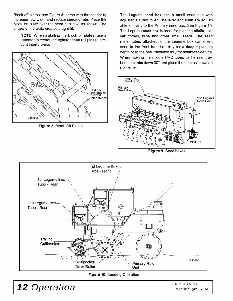
Block off plates, see Figure 8, come with the seeder toincrease row width and reduce seeding rate. Place theblock off plate over the seed cup hole as shown. Theshape of the plate creates a tight fit.
NOTE: When installing the block off plates, use ahammer to center the agitator shaft roll pins to pre-vent interference.
Figure 8. Block Off Plates
The Legume seed box has a small seed cup withadjustable fluted roller. The lever and shaft are adjust-able similarly to the Primary seed box. See Figure 15.The Legume seed box is ideal for planting alfalfa, clo-ver, forbes, rape and other small seeds. The seedmeter tubes attached to the Legume box can divertseed to the front transition tray for a deeper plantingdepth or to the rear transition tray for shallower depths.When moving the middle PVC tubes to the rear tray,bend the tabs down 90° and place the tube as shown inFigure 18.
Figure 9. Seed boxes
Figure 10. Seeding Operation
(Rev. 4/25/2018)
Operation 13MAN1074 (9/15/2014)
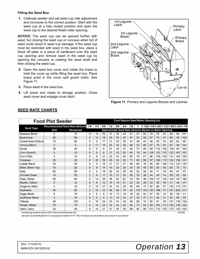
Filling the Seed Box1. Calibrate seeder and set seed cup rate adjustment
and concaves to the correct position. Start with theseed cup at a fully closed position and open theseed cup to the desired fluted roller opening.
NOTICE: The seed cup can be opened further withseed, but closing the seed cup or concave when full ofseed could result in seed cup damage. If the seed cupmust be restricted with seed in the seed box, place ablock off plate or a piece of cardboard over the seedcup opening and remove seed in the seed cup byopening the concave or rotating the seed shaft andthen closing the seed cup.
2. Open the seed box cover and rotate the brace tohold the cover up while filling the seed box. Placebrace point in the cover spill guard notch. SeeFigure 11.
3. Place seed in the seed box.
4. Lift brace and rotate to storage position. Closeseed cover and engage cover latch.
SEED RATE CHARTS
Figure 11. Primary and Legume Braces and Latches
(Rev. 11/14/2014)

14 Operation MAN1074 (9/15/2014)
Seed Rate Adjustment
Tractor speed and seed flow settings are critical forproper seed population. Use the calibration tray toadjust the seed cups for the desired seeding rate. Trac-tor speed (normally 2-5 mph) should be established sothat uniform seed incorporation occurs with the actionof the rollers.
Seed Rate
Adjust the flow control lever (Figure 12 and Figure 15)as needed for the seed being used and the populationdesired. To adjust, loosen the plastic knob, move todesired position and re-tighten the knob. 0 indicates aclosed seed cup while 1-7/8 indicates a fully open Pri-mary seed cup. 1-3/16 indicates a fully open Legumeseed cup.
Figure 12. Primary Seed Rate Adjustment Lever
Before seeding an area, adjust the top link so that it isin the middle of the slot with the seeder on the ground.
NOTE: It is normal for the seeder to pitch forwardat maximum disc angle when the tractor top link isin the slot.
Figure 13. Primary Seed Pointer
Primary Seed Cup Concave Lever AdjustmentThe Primary seed cup comes equipped with an adjust-able concave to handle a wide variety of seed sizes.For small seeds, including grass seeds, the concaveshould be at the highest position. This position will pre-vent the loss of seed flowing through the seed cup. Forlarger seeds, including soybeans, the concave shouldbe moved to a lower position. For minimum seed rates,the concave should only be opened to the size of theseed. This will prevent cracking of large seeds by theseed cup. Opening further will increase seed rates.See Figure 14.
DP2
DP4

Operation 15MAN1074 (9/15/2014)
Figure 14. Primary Seed Cup Concave Adjustment
Legume Seed Cup
The front Legume seed box is equipped with PVCtubes to place the legume seed in the transition tray forthe Primary seed box, ahead of the cultipacker driveroller. The front legume PVC tubes can be repositionedin the Legume transition tray for seed to be droppedahead of the cultipacker. See Figure 18.
Figure 15. Legume Seed Rate Adjustment Lever
Figure 16. Legume Seed Pointer
Figure 17. Legume Tubes - Front
Figure 18. Legume Tube - Rear Tray
Operating Tips
IMPORTANT■ Before closing down the cup (reducing rates),the operator should make certain that the cups arenot full of seed. If cups are full of seed (especiallysmall, round, hard seed), it may be necessary tocover the meter holes and run seeder a short dis-tance to reduce level of seeds in meter. Failure todo so could result in damage to seed cup.
■ Do not operate seeder in reverse. Operatingseeder in reverse may result in damage to seedboxes and chain drive system.
1. Do not allow dirt to build up on the roller sprockets.Clean sprockets and chain as needed. Excessivebuildup of material can cause damage to the rollerand idler shafts.
2. Always run the drive chain with some slack in thechain. An extremely tight chain can damage theroller shaft, the roller bearings, and the idler shaftand bearing.
DP16DP18
Concave Open - Maximum PositionConcave
Closed
Concave
DP3
DP5
DP6
Front TubeRear Tube
DP7
(Rev. 4/25/2018)
16 Operation MAN1074 (9/15/2014)
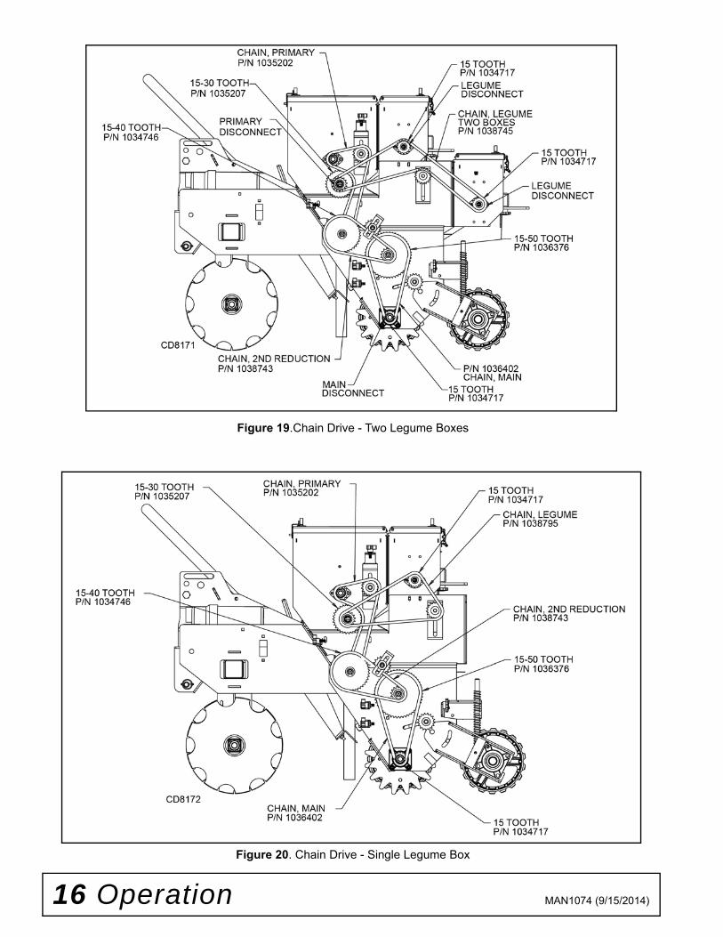
Figure 19.Chain Drive - Two Legume Boxes
Figure 20. Chain Drive - Single Legume Box

Operation 17MAN1074 (9/15/2014)
Cultipacker
A cast iron or nylon trailing cultipacker with springloaded down pressure is available as optional equip-ment with the Food Plot Seeder.
The trailing cultipacker is used to firm the seed bed forsmall seeds and increase seed-to-soil contact. The cul-tipacker is equipped to operate through an inclusiveangle of 37°. The nylon cultipacker spring system pro-vides the down pressure needed for an optimizedseedbed. When raising the seeder, the cultipacker willswing until it reaches its lower stop. When raising theseeder use a slow and steady motion to reduce theimpact loading of the cultipacker on the frame stop. Aslot and 1/2" hardware are provided to hold the culti-packer in a fixed position. To achieve a raised position,move the cultipacker into a ditch or trailer ramp toassist in lifting. Stop the engine of the power unit andthen tighten the cultipacker retainer to keep the culti-packer “raised."
Calibration TrayAn optional calibration tray is available to assist inadjusting the seed cups for the desired seeding rate.The calibration tray can be used with the seeder in thestationary position or as it is pulled over a short dis-tance of the seedbed. See Figure 21.
Figure 21. Calibration Tray
Stationary Calibration Procedure - Legume and Primary Seed Boxes
Equipment
1. One or two pounds of sample seed.
2. Optional calibration tray.
3. One scale capable of measuring ounces orhundreths of a pound.
Procedure1. Position tractor and seeder on a level surface.2. Adjust seed meter to closed position if applicable.3. Stop engine and set parking brake.
4. Disconnect seed box from seeder chain drive byremoving pin from seed box driven sprocket(Primary or Legume). See Figure 19.
5. Place seed over two seed meters closest to rightend of seeder.
6. Remove optional calibration tray (34 cu. in.capacity) from storage location. Install tray indesignated collection slot and tighten againstframe with two plastic nuts. Remove small PVCtubes from two right most seed cups. For primaryseed box, place tray or can at bottom of PVCtubes, or remove PVC tubes from primary seedcups.
7. Open seed cups to desired position (refer to chartfor estimate) and lock into place.
8. Use optional crank or a 12-pt socket and turnPrimary seed cup shaft or Legume seed cup shaftcounter-clockwise. See stationary calibration charton page 18 for number of shaft turns. (12-pt –3/4"or 19 mm socket fits over primary seed cup shaft.12-pt 12 mm socket fits over Legume seed cupshaft)
9. Carefully remove calibration tray to retrievecollected seed. Weigh seed and use formula todetermine seed rate. See page 18.
10. If seed rate is not correct, adjust seed cupopenings and repeat steps 7 through 9.
11. Return calibration tray and crank to storagepositions when finished. Reattach PVC tubes toseed cups.
Mobile Calibration Procedure - All Seed Boxes
Equipment1. One or two pounds of sample seed.2. Optional calibration tray.3. One scale capable of measuring ounces or
hundreths of a pound.Procedure1. Position tractor and seeder on a level surface.
2. Adjust seed meter to closed position if applicable.
3. Place seed over two seed meters closest to rightend of seeder.
4. Make sure the seed box being calibrated isconnected to chain drive. Disconnect other seedboxes by removing pin from seed box drivensprocket.

18 Operation MAN1074 (9/15/2014)
5. For first legume seed box, remove small PVC seedtubes from two right most seed cups. For primaryseed box, remove large PVC tubes or collect seedat bottom of PVC tubes with a can. For secondlegume seed box, collect seed at bottom of PVCtubes with a can.
6. Remove optional calibration tray (34 cu. in.capacity) from storage location. Install tray indesignated collection slot and tighten againstframe with two plastic nuts.
7. Open seed cups to desired position (refer to chartfor estimate) and lock into place.
8. Lower seeder to the ground and travel 100 feet.
9. Turn off engine and set parking brake.
10. Carefully remove calibration tray to retrievecollected seed. Weigh seed and use formula todetermine seed rate.
11. If seed rate is not correct, adjust seed cupopenings and repeat steps 6 through 9.
12. Return calibration tray to storage position whenfinished. Reattach PVC tubes to seed cups.
CALIBRATION FORMULA
Stationary Calibration ChartNo. of Turns to simulate traveling 100 ft with 2 seed meters
Multiply weight of seed captured during calibration (in pounds) by 373.4.
Example: .15 lbs collected with 2.1 turns of seed cup
.15 lbs x 373.4 = 56 lbs / acre
NOTE: Overlapping, primary seed cup concaveposition, and rough terrain/fast travel speeds willimpact seed metering accuracy.
Conversion for grams to pounds:
453.6 grams / 1 pound OR
.0022 pounds / 1 gram
Conversion for ounces to pounds:
16 ounces / 1 pound OR
.0625 pounds / 1 ounce
PRE-OPERATION CHECK LIST
(OWNER’S RESPONSIBILITY)
___ Review and follow all safety rules and safetydecal instructions on page 5 through page 8.
___ Check that equipment is properly and securelyattached to tractor.
___ Check that all safety decals are installed and ingood condition. Replace if damaged.
___ Do not allow riders.
___ Check that all hardware is properly installed andsecured.
___ Check that shields and guards are properlyinstalled and in good condition. Replace if dam-aged.
___ Check all lubrication points and grease asinstructed in Lubrication Information, Figure 22.
___ Make sure tractor ROPS or ROPS cab and seatbelt are in good condition. Keep seat beltsecurely fastened during operation.
1st Reduction
2nd
Reduction3rd
ReductionPrimary
Seed ShaftTurns
LegumeSeed Shaft
Turns
Middle Drive Roller
Food PlotSeed Drive 15-50 15-40 15-30 2.1 2.1 Nylon
Food Plot Seed Drive 15-50 15-40 15-30 2.5 2.5 Spiked
(Rev 9/20/2017)

Owner Service 19MAN1074 (9/15/2014)
OWNER SERVICEThe information in this section is written for operatorswho possess basic mechanical skills. If you need help,your Woods dealer has trained service techniciansavailable. For your protection, read and follow thesafety information in this manual.
NEVER GO UNDERNEATH EQUIPMENT. Neverplace any part of the body underneath equipmentor between moveable parts even when the enginehas been turned off. Hydraulic system leak-down,hydraulic system failures, mechanical failures, ormovement of control levers can cause equipmentto drop or rotate unexpectedly and cause severeinjury or death.
• Service work does not require going under-neath implement.• Read Operator’s Manual for service instruc-tions or have service performed by a qualifiedservice center.
Keep all persons away from operator controlarea while performing adjustments, service, ormaintenance. Before dismounting power unit or performingany service or maintenance, follow these steps:disengage power to equipment, lower the 3-pointhitch and all raised components to the ground,operate valve levers to release any hydraulic pres-sure, set parking brake, stop engine, remove key,and unfasten seat belt.
Always wear relatively tight and belted clothingto avoid getting caught in moving parts. Wearsturdy, rough-soled work shoes and protectiveequipment for eyes, hair, hands, hearing, and head;and respirator or filter mask where appropriate.
Tightening Cultipacker Wheel Assembly1. Place cultipacker on level, dry surface, with the
cultipacker cast iron wheels on the ground.2. Loosen 1/2” flange nuts and bolts on cast iron end
clamps.
3. Use a pry bar to tighten the wheels together.4. Retighten the 1/2” flange nuts and bolts on the
clamps.
Removing Cultipacker Shaft From Frame1. Place cultipacker on level, dry surface, with the
cultipacker cast iron wheels on the ground.2. Loosen bearing set screws with 5/32” Allen
wrench. Place a punch in he eccentric lockingcollar punch hole and tap the collar loose in theopposite direction of shaft operation.
3. Remove 1/2” flange lock nuts and bolts frombearing assembly. Repair or replace cultipackerassembly as needed or refer to tighteningcultipacker wheel assembly if applicable.
4. Match holes in cultipacker frame with holes inbearings and assemble with 1/2” bolts and flangelock nuts.
5. Lock eccentric bearing collars to cultipacker shaftby driving the collar in the direction of forwardtravel by placing a punch in the hole in the collarand driving it with a hammer. Secure collar to shaftwith set screw.
LUBRICATION INFORMATION
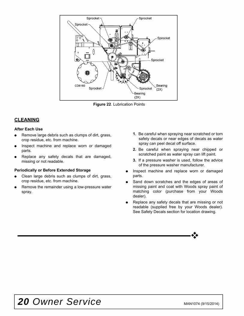
1. Lubricate all bearing housings every 8 hours.Bearing housings are located on each end ofrollers as indicated by grease fitting. See Figure22.
2. Lubricate chains and sprockets (with grease zerks)every 50 hours or season whichever is shorter. Theseed boxes are sealed with 3M 760 sealant. If aleak occurs in the seed box apply a 3/16” bead of3M 760 sealant to eliminate any leaks. The tackfree time is 30 minutes with full cure in 24 hours.
3. Clean fittings prior to lubrication. Do not letexcessive grease build up around lubricationpoints.
NOTE: One pump of a good grade multi-purposegrease should be sufficient in most cases. Harsh or dryconditions may require more frequent lubrication.
�������
CAUTION
Bearings with grease zerks
QTY Sprockets with grease zerks
QTY
Drive Roller 2 Primary Box 2Disc 0 Legume Box 2
Cultipacker 2 Seeder Frame 2Seed Boxes 0
(Rev. 4/1/2015)
20 Owner Service MAN1074 (9/15/2014)
Figure 22. Lubrication Points
CLEANING
After Each Use● Remove large debris such as clumps of dirt, grass,
crop residue, etc. from machine.● Inspect machine and replace worn or damaged
parts.● Replace any safety decals that are damaged,
missing or not readable.
Periodically or Before Extended Storage● Clean large debris such as clumps of dirt, grass,
crop residue, etc. from machine.● Remove the remainder using a low-pressure water
spray.
1. Be careful when spraying near scratched or tornsafety decals or near edges of decals as waterspray can peel decal off surface.
2. Be careful when spraying near chipped orscratched paint as water spray can lift paint.
3. If a pressure washer is used, follow the adviceof the pressure washer manufacturer.
● Inspect machine and replace worn or damagedparts.
● Sand down scratches and the edges of areas ofmissing paint and coat with Woods spray paint ofmatching color (purchase from your Woodsdealer).
● Replace any safety decals that are missing or notreadable (supplied free by your Woods dealer).See Safety Decals section for location drawing.
Assembly 21MAN1074 (9/15/2014)
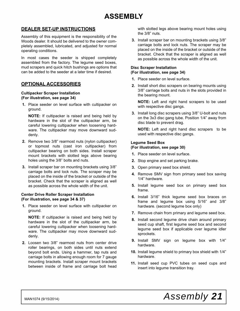
ASSEMBLYDEALER SET-UP INSTRUCTIONSAssembly of this equipment is the responsibility of theWoods dealer. It should be delivered to the owner com-pletely assembled, lubricated, and adjusted for normaloperating conditions.
In most cases the seeder is shipped completelyassembled from the factory. The legume seed boxes,mud scrapers and quick hitch bushings are options thatcan be added to the seeder at a later time if desired.
OPTIONAL ACCESSORIES
Cultipacker Scraper Installation (For illustration, see page 34)1. Place seeder on level surface with cultipacker on
ground.
NOTE: If cultipacker is raised and being held byhardware in the slot of the cultipacker arm, becareful lowering cultipacker when loosening hard-ware. The cultipacker may move downward sud-denly.
2. Remove two 3/8” rearmost nuts (nylon cultipacker)or topmost nuts (cast iron cultipacker) fromcultipacker bearing on both sides. Install scrapermount brackets with slotted legs above bearingholes using the 3/8” bolts and nuts.
3. Install scraper bar on mounting brackets using 3/8”carriage bolts and lock nuts. The scraper may beplaced on the inside of the bracket or outside of thebracket. Check that the scraper is aligned as wellas possible across the whole width of the unit.
Center Drive Roller Scraper Installation (For illustration, see page 34 & 37)1. Place seeder on level surface with cultipacker on
ground. NOTE: If cultipacker is raised and being held byhardware in the slot of the cultipacker arm, becareful lowering cultipacker when loosening hard-ware. The cultipacker may move downward sud-denly.
2. Loosen two 3/8” rearmost nuts from center driveroller bearings, on both sides until nuts extendbeyond bolt ends. Using a hammer, tap nuts andcarriage bolts in allowing enough room for 7 gaugemounting brackets. Install scraper mount bracketsbetween inside of frame and carriage bolt head
with slotted legs above bearing mount holes usingthe 3/8” nuts.
3. Install scraper bar on mounting brackets using 3/8”carriage bolts and lock nuts. The scraper may beplaced on the inside of the bracket or outside of thebracket. Check that the scraper is aligned as wellas possible across the whole width of the unit.
Disc Scraper Installation (For illustration, see page 34)1. Place seeder on level surface.2. Install short disc scrapers on bearing mounts using
3/8” carriage bolts and nuts in the slots provided inthe bearing mount.
NOTE: Left and right hand scrapers to be usedwith respective disc gangs.
3. Install long disc scrapers using 3/8” U-bolt and nutson the 3x3 disc gang tube. Position 1/4” away fromdisc blade to prevent drag. NOTE: Left and right hand disc scrapers to beused with respective disc gangs.
Legume Seed Box (For illustration, see page 30)1. Place seeder on level surface.
2. Stop engine and set parking brake.3. Open primary seed box shield.4. Remove SMV sign from primary seed box saving
1/4” hardware.
5. Install legume seed box on primary seed boxframe.
6. Install 3/16” thick legume seed box braces onframe and legume box using 5/16” and 3/8”hardware. (second legume box only)
7. Remove chain from primary and legume seed box.8. Install second legume drive chain around primary
seed cup shaft, first legume seed box and secondlegume seed box if applicable over legume idlersprockets.
9. Install SMV sign on legume box with 1/4”hardware.
10. Install legume shield to primary box shield with 1/4”hardware.
11. Install seed cup PVC tubes on seed cups andinsert into legume transition tray.

22 Dealer Check Lists MAN1074 (9/15/2014)
DEALER CHECK LISTS
PRE-DELIVERY CHECK LIST(DEALER’S RESPONSIBILITY)
Inspect the equipment thoroughly after assembly toensure it is set up properly before delivering it to thecustomer.
The following check lists are a reminder of points toinspect. Check off each item as it is found satisfactoryor after proper adjustment is made.
___ Check that all safety decals are installed and ingood condition. Replace if damaged.
___ Check that shields and guards are properlyinstalled and in good condition. Replace if dam-aged.
___ Check all bolts to be sure they are properlytorqued.
___ Check that all cotter pins and safety pins areproperly installed. Replace if damaged.
___ Check and grease all lubrication points as identi-fied in lubrication information on page 20.
DELIVERY CHECK LIST(DEALER’S RESPONSIBILITY)
___ Show customer how to make adjustments andselect proper ground speed.
___ Show customer the safe, proper procedures to beused when mounting, dismounting, and storingequipment.
___ Make customer aware of optional equipmentavailable so that customer can make properchoices as required.
___ Instruct customer how to lubricate and explainimportance of lubrication.
___ Point out the safety decals. Explain their meaningand the need to keep them in place and in goodcondition. Emphasize the increased safety haz-ards when instructions are not followed.
___ Present Operator's Manual and request that cus-tomer and all operators read it before operatingequipment. Point out the manual safety rules,explain their meanings and emphasize theincreased safety hazards that exist when safetyrules are not followed.
___ Explain to customer the potential crushing haz-ards of going underneath raised equipment.Explain that blocking up prevents equipmentdropping from hydraulic leak down, hydraulic sys-tem failures or mechanical component failures.
___ Point out all guards and shields. Explain theirimportance and the safety hazards that existwhen not kept in place and in good condition.
___ Explain to customer that when transporting theunit on a public road to comply with all state andlocal lighting/marking laws.
Parts 23MAN1074 (9/15/2014)
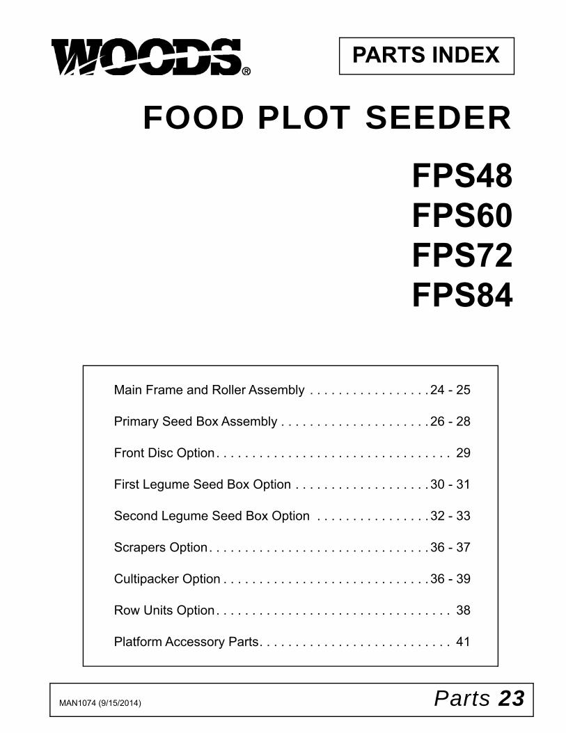
PARTS INDEX
Main Frame and Roller Assembly . . . . . . . . . . . . . . . . . 24 - 25
Primary Seed Box Assembly . . . . . . . . . . . . . . . . . . . . . 26 - 28
Front Disc Option. . . . . . . . . . . . . . . . . . . . . . . . . . . . . . . . . 29
First Legume Seed Box Option . . . . . . . . . . . . . . . . . . . 30 - 31
Second Legume Seed Box Option . . . . . . . . . . . . . . . . 32 - 33
Scrapers Option. . . . . . . . . . . . . . . . . . . . . . . . . . . . . . . 36 - 37
Cultipacker Option . . . . . . . . . . . . . . . . . . . . . . . . . . . . . 36 - 39
Row Units Option. . . . . . . . . . . . . . . . . . . . . . . . . . . . . . . . . 38
Platform Accessory Parts. . . . . . . . . . . . . . . . . . . . . . . . . . . 41
FOOD PLOT SEEDER
FPS48 FPS60 FPS72FPS84

24 Parts MAN1074 (9/15/2014)
FPS48, FPS60, FPS72 & FPS84 MAIN FRAME & ROLLER ASSEMBLY
(Rev. 11/27/2017)

Parts 25MAN1074 (9/15/2014)
FPS48, FPS60, FPS72, FPS84 MAIN FRAME & ROLLER ASSEMBLY PARTS LIST
REF FPS48 FPS60 FPS72 FPS84 QTY DESCRIPTION1 ………… ………… ………… ………… 1 Frame, seeder2 103865348RP 103865360RP 103865372RP 103865384RP 1 Drive roller, cultipacker
-OR- -OR- -OR- -OR- -OR-2 103877648RP 103877660RP 103877672RP 103877684RP 1 Drive roller, spiked3 W301117 W301117 W301117 W301117 8 3/8 NC x 1-3/4 carriage bolt ZP4 20A920 20A920 20A920 20A920 2 1" bearing with housing5 62043* 62043* 62043* 62043* 2 1/4 x 1-3/4 klik pin6 14350* 14350* 14350* 14350* 34 3/8 NC flanged lock nut7 1028375* 1028375* 1028375* 1028375* 3 3/8 push-on nut8 1035646 1035646 1035646 1035646 1 3/4 x 6-1/4 pin, bent w/ clip9 1637* 1637* 1637* 1637* 1 1/2 NC x 3-1/2 cap screw GR5 ZP
10 1035651RP 1035651RP 1035651RP 1035651RP 2 Sleeve, .56 x .75 x .7511 3598* 3598* 3598* 3598* 2 1/2 SAE flat washer12 11900* 11900* 11900* 11900* 1 1/2 NC flanged lock nut13 HBL233 HBL233 HBL233 HBL233 2 .875 x 6.94 headless pin14 27542* 27542* 27542* 27542* 4 7/16 x 11/32 klik pin15 56598 56598 56598 56598 2 Sleeve, .885 x 1.125 x 2.6216 24409* 24409* 24409* 24409* 2 5/16 NC x 1 carriage bolt ZP17 14139* 14139* 14139* 14139* 2 5/16 NC flanged lock nut ZP18 1003828 1003828 1003828 1003828 1 Manual tube19 1038669 1038669 1038728 1038728 2 Mount, lower hitch20 W302207* W302207* W302207* W302207* 9 3/4 NC flanged lock nut21 1035193RP 1035193RP 1035193RP 1035193RP 1 Handle25 1034668 1034668 1034668 1034668 4 3/4 x 3.81 x 4.31 u-bolt26 1002018 1002018 1002018 1002018 1 Sleeve, .81 x 1.25 x 2.1227 31207* 31207* 31207* 31207* 1 3/4 NC x 4 cap screw GR5 ZP30 1037467 1037467 1037467 1037467 8 3/8 NC x 1-1/2 button head screw31 1038651P (21) 1038651P (26) 1038651P (31) 1038651P (36) 11-1/2" ring, cultipacker32 1038654RP 1038654RP 1038654RP 1038654RP 2 End cap, star roller33 20973* 20973* 20973* 20973* 3 3/8 NC x 1-1/4 carriage bolt GR534 103869225RP 103869225RP 103869225RP 103869225RP 1 Mount, cultipacker stop LH35 1038734RP (6) ------- ------- 1038734RP (4) Shim, cultipacker 14 GA36 1038732RP (4) ------- 1038732RP (2) 1038732RP(4) Shim, cultipacker 1/437 1036370 1036370 1036370 1036370 1 Crank, optional38 1035232RP 1035232RP 1035232RP 1035232RP 1 Mount, transition tray, optional39 66840 66840 66840 66840 2 3/8 NC knob, 3 prong40 6697* 6697* 6697* 6697* 2 3/8 NC x 1 carriage bolt GR5 ZP41 1035236RP 1035236RP 1035236RP 1035236RP 1 Calibration tray, optional42 1038749 1038749 1038749 1038749 2 Sleeve, .91 x 1.44 x 3.50
* Standard hardware, obtain locally
(Rev. 7/24/2019)

26 Parts MAN1074 (9/15/2014)
FPS48, FPS60, FPS72, FPS84 PRIMARY SEED BOX ASSEMBLY10
3635
4 - S
afet
y de
cal s
et
1036
355
- Mod
el d
ecal
set
1037
499
- Ins
truct
iona
l dec
al s
et
(Rev. 11/27/2017)

Parts 27MAN1074 (9/15/2014)
FPS48, FPS60, FPS72, FPS84 PRIMARY SEED BOX PARTS LISTREF FPS48 FPS60 FPS72 FPS84 QTY DESCRIPTION
1 103877948RP 103877960RP 103877972RP 103877984RP 1 Seedbox, Primary2 103569848RP 103569860RP 103569872RP 103569884RP 1 Cover, seedbox Primary3 1038723RP 1038723RP 1038723RP 1038723RP 1 Mount, bearing Primary4 1034739RP 1034739RP 1034739RP 1034739RP 1 Tube, transmission5 1034694 1034694 1034694 1034694 3 1-1/8 bearing, flangette6 1035207 1035207 1035207 1035207 1 Sprocket weldment7 1034717 1034717 1034717 1034717 2 Sprocket8 1038763RP 1038763RP 1038763RP 1038763RP 1 Lever, Primary9 24516RP 24516RP 24516RP 24516RP 1 Sleeve, 3/8 x 1/2 x 27/6410 1035197RP 1035197RP 1035197RP 1035197RP 1 Link11 1033294 1033294 1033294 1033294 4 3/8 NC x 1.00 knob, 3 prong LG12 1033293 1033293 1033293 1033293 4 3/8-16 spring nut, u-tapped13 1034693 1034693 1034693 1034693 2 3/4 bearing, flangette14 103869848RP 103869860RP 103869872RP 103869884RP 1 Shaft, Primary seedcup15 1034754 (7) 1034754 (8) 1034754 (10) 1034754 (12) Seedcup, large16 1034755 (7) 1034755 (8) 1034755 (10) 1034755 (12) Gate, seedcup, large17 1034712RP (14) 1034712RP (16) 1034712RP (20) 1034712RP (24) Washer, Primary seedcup18 1035188 (16) 1035188 (18) 1035188 (22) 1035188 (26) 1/8 x 1-1/4 roll pin19 1034756 (7) 1034756 (8) 1034756 (10) 1034756 (12) Feed roll, large20 1034747RP 1034747RP 1034747RP 1034747RP 1 Spool, shifter Primary21 103872048RP 103568560RP 103568572RP 103568584RP 1 Shaft, Primary agitator22 1034692 (14) 1034692 (16) 1034692 (20) 1034692 (24) 3/16 x 3-1/2 roll pin23 1035672RP 1035672RP 1035672RP 1035672RP 1 Lever, Primary & Native24 1036402 1036402 1036402 1036402 1 Chain, main, A2040, 40 link 25 20A635 20A635 20A635 20A635 2 Lid handle26 1001978* 1001978* 1001978* 1001978* 8 3/16 blind rivet, No. 6327 1038736RP 1038736RP 1038736RP 1038736RP 1 Shield, frame28 1035694RP 1035694RP 1035694RP 1035694RP 1 Brace, Primary29 1035202 1035202 1035202 1035202 1 Chain, Primary, A2040 46 link30 1034746 1034746 1034746 1034746 1 Sprocket, weldment 15-4031 1036376 1036376 1036376 1036376 1 Sprocket, weldment 15-5032 1035225 1035225 1035225 1035225 2 1/4 NC x .75 x .31 shoulder bolt33 1034698 (7) 1034698 (8) 1034698 (10) 1034698 (12) Spring34 78285 (14) 78285 (16) 78285 (20) 78285 (24) 5/16 NC x 3/4 YD screw, BTN HD35 W73163* (14) W73163* (16) W73163* (20) W73163* (24) 5/16 NC flanged whiz nut36 24409* 24409* 24409* 24409* 6 5/16NC x 1 carriage bolt, ZP37 14139* 14139* 14139*‘ 14139* 6 5/16 NC flanged lock nut, HD ZP38 6697* 6697* 6697* 6697* 31 3/8 NC x 1 carriage bolt, GR5 ZP39 14350* 14350* 14350* 14350* 34 3/8 NC flanged lock nut41 70065* 70065* 70065* 70065* 2 1/4 NC whiz nut42 11900* 11900* 11900* 11900* 3 1/2 NC flanged lock nut43 12296 12296 12296 12296 5 1/4-28 grease zerk44 SU910 SU910 SU910 SU910 4 .75 x1.0 x.75 bearing needle45 11036 11036 11036 11036 3 3/4 washer, 18 gauge46 35139 35139 35139 35139 2 .050 x .750 retainer ring48 1035651RP 1035651RP 1035651RP 1035651RP 2 Sleeve, .56 x .75 x .7549 854RP* 854RP* 854RP* 854RP* 3 1/2 flat washer, ZP50 27635* 27635* 27635* 27635* 1 1/2 NC x 3-1/2 carriage bolt51 62043* 62043* 62043* 62043* 2 1/4 x 1-3/4 klik pin52 976* 976* 976* 976* 1 3/8 NC x 1-1/2 cap screw GR5 ZP53 1035232RP 1035232RP 1035232RP 1035232RP 4 Mount, transition tray54 103873148RP 103873160RP 103873172RP 103873184RP 1 Seed tray, front55 103873348RP 103873360RP 103873372RP 103873384RP 1 Seed tray, rear
(Primary Seed Box Parts List Continued on Page 28)
(Rev. 7/24/2019)

28 Parts MAN1074 (9/15/2014)
FPS48, FPS60, FPS72, FPS84 PRIMARY SEED BOX PARTS LIST (CONTINUED)REF FPS48 FPS60 FPS72 FPS84 QTY DESCRIPTION57 1035677RP 1035677RP 1035677RP 1035677RP 2 Mount, frame shield58 1035669A 1035669A 1035669A 1035669A 1 Sealant, 3M 760 hybrid black 59 W70067 W70067 W70067 W70067 1 .25-20 x .5 whiz bolt TRSS60 5336* 5336* 5336* 5336* 1 1/4 flat washer, ZP61 62521* 62521* 62521* 62521* 1 1/4 NC flanged lock nut63 66840 66840 66840 66840 2 3/8 NC knob, 3 prong64 20973* 20973* 20973* 20973* 7 3/8 NC x 1-1/4 carriage bolt GR565 1038707RP 1038707RP 1038707RP 1038707RP 1 Mount, seed box Primary LH66 1038656RP 1038656RP 1038656RP 1038656RP 1 Mount, seed box Primary RH67 1034753 1034753 1034753 1034753 2 Sprocket, idler w/ bearing68 1035676 1035676 1035676 1035676 1 1/4 x 1-3/4 lock pin70 72628 72628 72628 72628 1 Sleeve, .5 x .75 x .5671 64672* 64672* 64672* 64672* 1 1/2 NC x 2-1/4 carriage bolt72 1038735RP 1038735RP 1038735RP 1038735RP 1 Shield, Primary seed box73 2864* (5) 2864* (5) 2864* (3) 2864* (3) 3/4 flat washer, ZP75 1038743 1038743 1038743 1038743 1 Chain, 2nd reduction 32 link76 1038794RP 1038794RP 1038794RP 1038794RP 1 Pointer, Primary77 21941* 21941* 21941* 21941* 1 1/4 NC wing nut, ZP78 1038744 1038744 1038744 1038744 2 Plug, 1/4 plastic black79 64812* 64812* 64812* 64812* 2 1/4 NC x 1/2 carriage bolt80 12735* 12735* 12735* 12735* 1 1/2 NC x 1-3/4 carriage bolt81 1028375* 1028375* 1028375* 1028375* 3 3/8 push-on bolt retainer
FA418 FA418 FA418 FA418 NS #40 single pitch conn linkFA419 FA419 FA419 FA419 NS #2040 double pitch conn link1002959 1002959 1002959 1002959 NS #40 single pitch offset link 1036354 1036354 1036354 1036354 NS Decal set, safety 1036355 1036355 1036355 1036355 NS Decal set, model
82 1037499 1037499 1037499 1037499 NS Decal set, instructional83 1038755RP 1038755RP 1038755RP 1038755RP 1 Shield, Primary seed box only84 1038695RP 1038695RP 1038695RP 1038695RP 1 Mount, shield85 1037388 1037388 1037388 1037388 1 Decal, FPS Primary seed chart
NS Not shown* Standard hardware, obtain locally
(Rev. 7/24/2019)
Parts 29MAN1074 (9/15/2014)
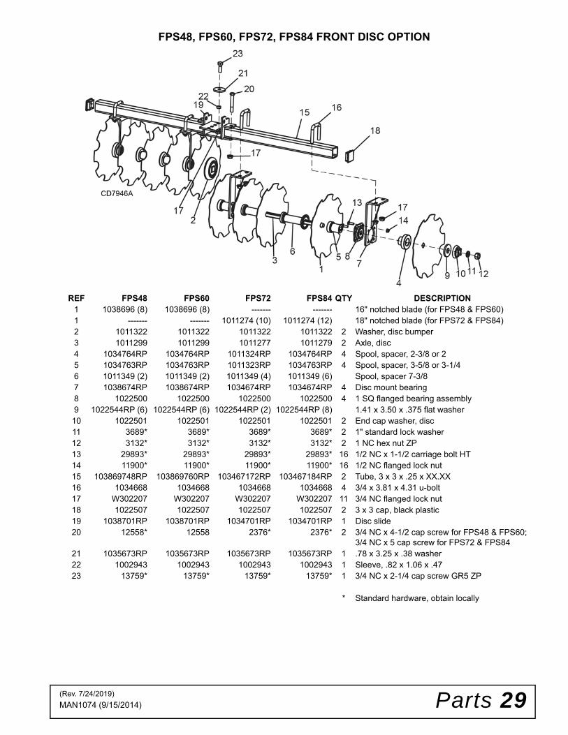
FPS48, FPS60, FPS72, FPS84 FRONT DISC OPTION
REF FPS48 FPS60 FPS72 FPS84 QTY DESCRIPTION1 1038696 (8) 1038696 (8) ------- ------- 16" notched blade (for FPS48 & FPS60)1 ------- ------- 1011274 (10) 1011274 (12) 18" notched blade (for FPS72 & FPS84)2 1011322 1011322 1011322 1011322 2 Washer, disc bumper3 1011299 1011299 1011277 1011279 2 Axle, disc4 1034764RP 1034764RP 1011324RP 1034764RP 4 Spool, spacer, 2-3/8 or 25 1034763RP 1034763RP 1011323RP 1034763RP 4 Spool, spacer, 3-5/8 or 3-1/46 1011349 (2) 1011349 (2) 1011349 (4) 1011349 (6) Spool, spacer 7-3/87 1038674RP 1038674RP 1034674RP 1034674RP 4 Disc mount bearing8 1022500 1022500 1022500 1022500 4 1 SQ flanged bearing assembly9 1022544RP (6) 1022544RP (6) 1022544RP (2) 1022544RP (8) 1.41 x 3.50 x .375 flat washer
10 1022501 1022501 1022501 1022501 2 End cap washer, disc11 3689* 3689* 3689* 3689* 2 1" standard lock washer12 3132* 3132* 3132* 3132* 2 1 NC hex nut ZP13 29893* 29893* 29893* 29893* 16 1/2 NC x 1-1/2 carriage bolt HT14 11900* 11900* 11900* 11900* 16 1/2 NC flanged lock nut15 103869748RP 103869760RP 103467172RP 103467184RP 2 Tube, 3 x 3 x .25 x XX.XX16 1034668 1034668 1034668 1034668 4 3/4 x 3.81 x 4.31 u-bolt17 W302207 W302207 W302207 W302207 11 3/4 NC flanged lock nut18 1022507 1022507 1022507 1022507 2 3 x 3 cap, black plastic19 1038701RP 1038701RP 1034701RP 1034701RP 1 Disc slide20 12558* 12558 2376* 2376* 2 3/4 NC x 4-1/2 cap screw for FPS48 & FPS60;
3/4 NC x 5 cap screw for FPS72 & FPS8421 1035673RP 1035673RP 1035673RP 1035673RP 1 .78 x 3.25 x .38 washer22 1002943 1002943 1002943 1002943 1 Sleeve, .82 x 1.06 x .4723 13759* 13759* 13759* 13759* 1 3/4 NC x 2-1/4 cap screw GR5 ZP
* Standard hardware, obtain locally
(Rev. 7/24/2019)
30 Parts MAN1074 (9/15/2014)
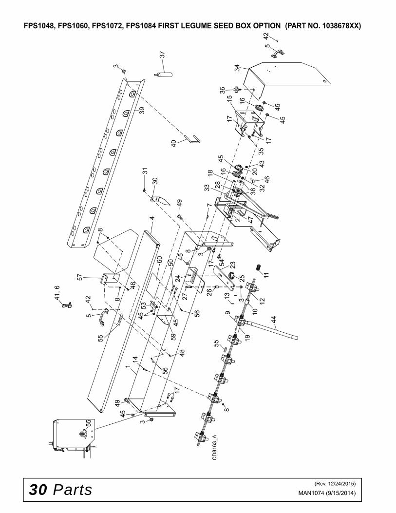
FPS1048, FPS1060, FPS1072, FPS1084 FIRST LEGUME SEED BOX OPTION (PART NO. 1038678XX)
(Rev. 12/24/2015)

Parts 31MAN1074 (9/15/2014)
FPS48, FPS60, FPS72, FPS84 FIRST LEGUME SEED BOX PARTS LIST (PART NO. 1038678XX)
REF FPS48 FPS60 FPS72 FPS84 QTY DESCRIPTION1 103517848RP 103517860RP 103517872RP 103517884RP 1 Seedbox, Legume2 12735* 12735* 12735* 12735* 1 1/2 NC x 1-3/4 carriage bolt3 14350* 14350* 14350* 14350* 9 3/8 NC flanged lock nut4 103569948RP 103569960RP 103569972RP 103569984RP 1 Cover, Legume seedbox5 20A635 20A635 20A635 20A635 2 Lid, handle6 1001994* 1001994* 1001994* 1001994* 4 1/8 No. 43 blind rivet7 1035225 1035225 1035225 1035225 2 1/4NC x .75 x .31 shoulder bolt 8 W70065* (20) W70065* (22) W70065* (26) W70065* (30) 1/4 NC whiz nut9 1034695 (7) 1034695 (8) 1034695 (10) 1034695 (12) Seedcup, small10 1034696 (7) 1034696 (8) 1034696 (10) 1034696 (12) Gate, seedcup, small11 1034697 (7) 1034697 (8) 1034697 (10) 1034697 (12) Feed roll, small12 103518648RP 103518660RP 103518672RP 103518684RP 1 Shaft, seedcup Legume13 1035187 (16) 1035187 (18) 1035187 (22) 1035187 (26) 1/8 x 7/8 roll pin14 W70067 (14) W70067 (16) W70067 (20) W70067 (24) .25-20 x .5 whiz bolt TRSS/MR15 1035195RP 1035195RP 1035195RP 1035195RP 1 Mount, bearing Legume16 1034693 1034693 1034693 1034693 2 3/4 bearing, flangette17 16148* 16148* 16148* 16148* 8 5/16NC x 3/4 carriage bolt ZP18 1034727RP 1034727RP 1034727RP 1034727RP 1 Tube, transmission19 1035625RP 1035625RP 1035625RP 1035625RP 1 Sleeve, shifter 20 1034717 1034717 1034717 1034717 1 Sprocket23 1035215RP 1035215RP 1035215RP 1035215RP 1 Lever, shifter 24 20973* 20973* 20973* 20973* 1 3/8 NC x 1-1/4 carriage bolt GR525 66840 66840 66840 66840 1 3/8 NC knob, 3 prong26 1035632RP 1035632RP 1035632RP 1035632RP 1 Sleeve, .39 x .63 x 1.0627 300157* 300157* 300157* 300157* 1 3/8 NC x 2-1/4 cap screw GR5 ZP28 1034753 1034753 1034753 1034753 1 Sprocket idler bearing30 1038793RP 1038793RP 1038793RP 1038793RP 1 Pointer, Legume31 21941* 21941* 21941* 21941* 2 1/4 NC wing nut, ZP32 11900* 11900* 11900* 11900* 1 1/2 NC flanged lock nut33 1038795 1038795 1038795 1038795 1 Chain, single Legume 42 link34 1038739RP 1038739RP 1038739RP 1038739RP 1 Shield, Legume35 1033293* 1033293* 1033293* 1033293* 1 3/8 - 16 spring nut u-tapped36 1033294 1033294 1033294 1033294 1 3/8 NC x 1.00 knob, 3 prong37 1035669A 1035669A 1035669A 1035669A 1 Sealant, 3M 760 hybrid black 38 854* 854* 854* 854* 2 1/2 flat washer, ZP39 103874248 103874260 103874272 103874284 1 Seed tray, Legume40 1035662 1035662 1035662 1035662 2 3/8 x 3.43 x 3.56 u-bolt41 1001975 1001975 1001975 1001975 1 Flex draw latch42 1001978* 1001978* 1001978* 1001978* 8 3/16 No. 63 blind rivet43 12296 12296 12296 12296 1 1/4 28 straight fitting, 15/32L44 1038718 (7) 1038718(8) 1038718 (10) 1038718 (12) 11/16 ID x 24 PVC tube45 14139* 14139* 14139* 14139* 13 5/16 NC flanged lock nut HD ZP46 1035244 1035244 1035244 1035244 1 1/4 x 1-1/5 pin, detent47 2864* 2864* 2864* 2864* 1 3/4 flat washer, ZP48 5337* 5337* 5337* 5337* 2 1/4 NC x 1/2 cap screw GR549 6697* 6697* 6697* 6697* 4 3/8 x 1 carriage bolt GR5 ZP50 14562* 14562* 14562* 14562* 2 5/16 NC x 1 cap screw GR553 1035695RP 1035695RP 1035695RP 1035695RP 1 Brace, Legume54 24409* 24409* 24409* 24409* 2 5/16 NC x 1 carriage bolt, ZP55 1037499 1037499 1037499 1037499 1 Decal set, instructional56 64812* 64812* 64812* 64812* 4 1/4 NC x 1/2 carriage bolt57 1035229RP 1035229RP 1035229RP 1035229RP 1 SMV sign mount59 1038744 1038744 1038744 1038744 2 Plug, 1/4 plastic black60 1037389 1037389 1037389 1037389 1 Decal, FPS Legume seed chart
* Standard hardware, obtain locally
(Rev. 7/24/2019)

32 Parts MAN1074 (9/15/2014)
FPS48, FPS60, FPS72, FPS84 SECOND LEGUME SEED BOX OPTION (PART NO. 1038778XX)
(Rev. 12/24/2015)

Parts 33MAN1074 (9/15/2014)
FPS48, FPS60, FPS72, FPS84 SECOND LEGUME SEED BOX PARTS LIST (PART NO. 1038778XX)REF FPS48 FPS60 FPS72 FPS84 QTY DESCRIPTION
1 103517848RP 103517860RP 103517872RP 103517884RP 1 Seed box, Legume3 14350* 14350* 14350* 14350* 10 3/8 NC flanged lock nut4 103569948RP 103569960RP 103569972RP 103569984RP 1 Cover, Legume seed box5 20A635 20A635 20A635 20A635 1 Lid, handle6 1001994* 1001994* 1001994* 1001994* 4 1/8 No. 43 blind rivet7 1035225 1035225 1035225 1035225 2 1/4NC x .75 x .31 shoulder bolt 8 W70065* (23) W70065* (25) W70065* (29) W70065* (33) 1/4 NC whiz nut9 1034695 (7) 1034695 (8) 1034695 (10) 1034695 (12) Seedcup, small10 1034696 (7) 1034696 (8) 1034696 (10) 1034696 (12) Gate, seedcup, small11 1034697 (7) 1034697 (8) 1034697 (10) 1034697 (12) Feed roll, small12 103518648RP 103518660RP 103518672RP 103518684RP 1 Shaft, seedcup legume13 1035187 (16) 1035187 (18) 1035187 (22) 1035187 (26) 1/8 x 7/8 roll pin14 W70067 (14) W70067 (16) W70067 (20) W70067 (24) .25-20 x .5 whiz bolt TRSS/MR15 1035195RP 1035195RP 1035195RP 1035195RP 1 Mount, bearing legume16 1034693 1034693 1034693 1034693 2 3/4 bearing, flangette17 16148* 16148* 16148* 16148* 8 5/16NC x 3/4 carriage bolt ZP18 1034727RP 1034727RP 1034727RP 1034727RP 1 Tube, transmission19 1035625RP 1035625RP 1035625RP 1035625RP 1 Sleeve, shifter 20 1034717 1034717 1034717 1034717 1 Sprocket23 1035215RP 1035215RP 1035215RP 1035215RP 1 Lever, shifter 24 20973* 20973* 20973* 20973* 1 3/8 NC x 1-1/4 carriage bolt GR525 66840 66840 66840 66840 1 3/8 NC knob, 3 prong26 1035632RP 1035632RP 1035632RP 1035632RP 1 Sleeve, .39 x .63 x 1.0627 W300157* W300157* W300157* W300157* 1 3/8 NC x 2-1/4 cap screw GR5 ZP28 12169* 12169* 12169* 12169* 1 3/8 NC x 1-1/4 cap screw GR5 ZP30 1038695RP 1038695RP 1038695RP 1038695RP 1 Mount, shield Legume 2nd31 1038793RP 1038793RP 1038793RP 1038793RP 1 Pointer, Legume32 21941* 21941* 21941* 21941* 2 1/4 NC wing nut, ZP33 1038745 1038745 1038745 1038745 1 Chain, double Legume 66 link34 1038738RP 1038738RP 1038738RP 1038738RP 1 Shield, Legume, rear35 1033293* 1033293* 1033293* 1033293* 1 3/8 - 16 spring nut u-tapped36 1033294 1033294 1033294 1033294 1 3/8 NC x 1.00 knob, 3 prong37 1035669A 1035669A 1035669A 1035669A 1 Sealant, 3M 760 hybrid black 41 1001975 1001975 1001975 1001975 1 Flex draw latch42 1001978* 1001978* 1001978* 1001978* 4 3/16 No. 63 blind rivet43 12296 12296 12296 12296 1 1/4 28 straight fitting, 15/32L44 1038746RP (7) 1038746RP (8) 1038746RP (10) 1038746RP (12) 11/16 ID x 12 PVC tube45 14139* 14139* 14139* 14139* 13 5/16 NC flanged lock nut HD ZP46 1035244 1035244 1035244 1035244 1 1/4 x 1-1/5 pin, detent48 5337* 5337* 5337* 5337* 2 1/4 NC x 1/2 cap screw GR549 6697* 6697* 6697* 6697* 8 3/8 x 1 carriage bolt GR5 ZP50 14562* 14562* 14562* 14562* 2 5/16 NC x 1 cap screw GR551 1038787RP 1038787RP 1038787RP 1038787RP 1 Brace, Legume LH52 1038788RP 1038788RP 1038788RP 1038788RP 1 Brace, Legume, RH53 1035695RP 1035695RP 1035695RP 1035695RP 1 Brace, Legume54 24409* 24409* 24409* 24409* 2 5/16 NC x 1 carriage bolt, ZP55 1037499 1037499 1037499 1037499 1 Decal set, instructional56 64812* 64812* 64812* 64812* 4 1/4 NC x 1/2 carriage bolt57 1035229RP 1035229RP 1035229RP 1035229RP 1 SMV sign mount
FA418 FA418 FA418 FA418 NS #40 single pitch conn linkFA419 FA419 FA419 FA419 NS #2040 double pitch conn link1002959 1002959 1002959 1002959 NS #40 single pitch offset link
58 1037389 1037389 1037389 1037389 1 Decal, FPS Legume seed chartNS Not shown* Standard hardware, obtain locally
(Rev. 7/24/2019)

34 Parts MAN1074 (9/15/2014)
FPS48, FPS60, FPS72, FPS84 DISC SCRAPER OPTION (PART NO. 1036470)
FPS48, FPS60, FPS72, FPS84 SCRAPER CULTIPACKER DRIVE ROLLER (PART NO. 1036471XX) AND NYLON CULTIPACKER (PART NO. 1036421XX)
Parts 35MAN1074 (9/15/2014)
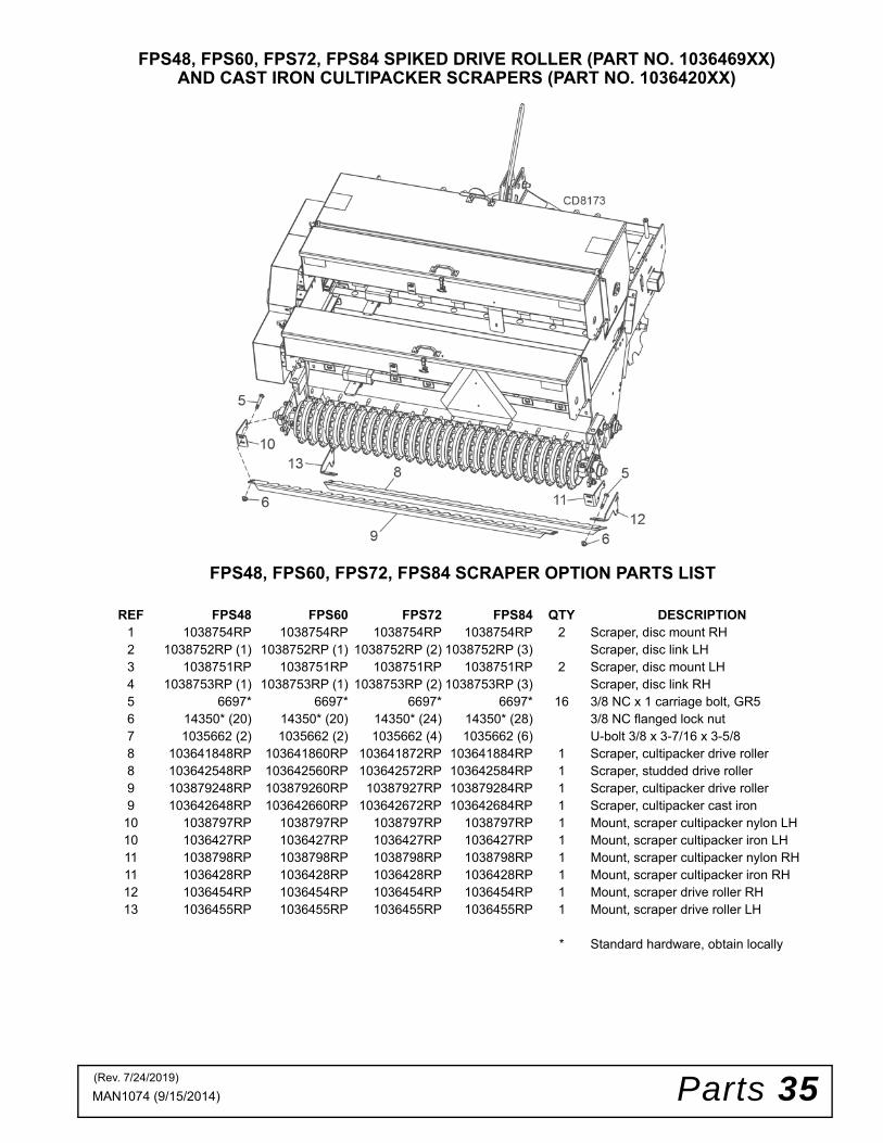
FPS48, FPS60, FPS72, FPS84 SCRAPER OPTION PARTS LIST
REF FPS48 FPS60 FPS72 FPS84 QTY DESCRIPTION1 1038754RP 1038754RP 1038754RP 1038754RP 2 Scraper, disc mount RH2 1038752RP (1) 1038752RP (1) 1038752RP (2) 1038752RP (3) Scraper, disc link LH3 1038751RP 1038751RP 1038751RP 1038751RP 2 Scraper, disc mount LH4 1038753RP (1) 1038753RP (1) 1038753RP (2) 1038753RP (3) Scraper, disc link RH5 6697* 6697* 6697* 6697* 16 3/8 NC x 1 carriage bolt, GR56 14350* (20) 14350* (20) 14350* (24) 14350* (28) 3/8 NC flanged lock nut7 1035662 (2) 1035662 (2) 1035662 (4) 1035662 (6) U-bolt 3/8 x 3-7/16 x 3-5/88 103641848RP 103641860RP 103641872RP 103641884RP 1 Scraper, cultipacker drive roller8 103642548RP 103642560RP 103642572RP 103642584RP 1 Scraper, studded drive roller9 103879248RP 103879260RP 10387927RP 103879284RP 1 Scraper, cultipacker drive roller9 103642648RP 103642660RP 103642672RP 103642684RP 1 Scraper, cultipacker cast iron
10 1038797RP 1038797RP 1038797RP 1038797RP 1 Mount, scraper cultipacker nylon LH10 1036427RP 1036427RP 1036427RP 1036427RP 1 Mount, scraper cultipacker iron LH11 1038798RP 1038798RP 1038798RP 1038798RP 1 Mount, scraper cultipacker nylon RH11 1036428RP 1036428RP 1036428RP 1036428RP 1 Mount, scraper cultipacker iron RH12 1036454RP 1036454RP 1036454RP 1036454RP 1 Mount, scraper drive roller RH13 1036455RP 1036455RP 1036455RP 1036455RP 1 Mount, scraper drive roller LH
* Standard hardware, obtain locally
FPS48, FPS60, FPS72, FPS84 SPIKED DRIVE ROLLER (PART NO. 1036469XX)AND CAST IRON CULTIPACKER SCRAPERS (PART NO. 1036420XX)
(Rev. 7/24/2019)

36 Parts MAN1074 (9/15/2014)
FPS48, FPS60, FPS72, FPS84 NYLON CULTIPACKER OPTION (PART NO. 1038777XX)
REF FPS48 FPS60 FPS72 FPS84 QTY DESCRIPTION1 103878048RP 103878060RP 103878072RP 103878084RP 1 Shaft, cultipacker2 1033740 1033740 1033740 1033740 2 1.38 flanged 4 bolt bearing3 1038699RP 1038699RP 1038699RP 1038699RP 2 Arm, cultipacker4 1034676 1034676 1034676 1034676 4 1-3/4 clamp5 1038781P (20) 1038781P (25) 1038781P (30) 1038781P (35) Cultipacker, plastic6 12735* 12735* 12735* 12735* 2 1/2 NC x 1-3/4 carriage bolt HT7 11900* 11900* 11900* 11900* 14 1/2 NC flanged lock nut8 1257* 1257* 1257* 1257* 2 3/4 flat washer ZP9 735* 735* 735* 735* 2 3/4 NC x 2 cap screw GR5
10 W302207* W302207* W302207* W302207* 2 3/4 NC flanged lock nut11 3489* 3489* 3489* 3489* 4 1/2 NC x 3 cap screw GR512 854* 854* 854* 854* 2 1/2 flat washer, ZP13 20A111 20A111 20A111 20A111 2 Stud, spring14 20A125 20A125 20A125 20A125 2 Spring15 29485* 29485* 29485* 29485* 4 3/4 NC jam nut ZP16 10284* 10284* 10284* 10284* 8 1/2 NC x 2 carriage bolt19 20973* 20973* 20973* 20973* 2 3/8 NC x 1-1/4 carriage bolt GR5 ZP20 14350* 14350* 14350* 14350* 4 3/8 NC flanged lock nut21 7747* 7747* 7747* 7747* 2 3/8 NC x 3 cap screw GR522 1038693RP 1038693RP 1038693RP 1038693RP 1 Mount, cultipacker stop RH
* Standard hardware, obtain locally
(Rev. 7/24/2019)

Parts 37MAN1074 (9/15/2014)
FPS48, FPS60, FPS72, FPS84 CAST IRON CULTIPACKER OPTION (PART NO. 1034655XX)
REF FPS48 FPS60 FPS72 FPS84 QTY DESCRIPTION1 103465048RP 103465060RP 103465072RP 103465084RP 1 Shaft, cultipacker2 1033740 1033740 1033740 1033740 2 1.38 flanged 4 bolt bearing3 1035210RP 1035210RP 1035210RP 1035210RP 2 Mount, bearing4 1034676 1034676 1034676 1034676 4 1-3/4 clamp5 1034651 (22) 1034651 (26) 1034651 (32) 1034651 (37) Cultipacker, cast iron6 12735* 12735* 12735* 12735* 2 1/2 NC x 1-3/4 carriage bolt HT7 11900* 11900* 11900* 11900* 14 1/2 NC flanged lock nut8 1257* 1257* 1257* 1257* 2 3/4 flat washer ZP9 735* 735* 735* 735* 2 3/4 NC x 2 cap screw GR5
10 W302207* W302207* W302207* W302207* 2 3/4 NC flanged lock nut11 5621* 5621* 5621* 5621* 4 1/2 NC x 2-3/4 cap screw GR512 20973* 20973* 20973* 20973* 2 3/8 NC x 1-1/4 carriage bolt GR513 14350* 14350* 14350* 14350* 4 3/8 NC flanged lock nut14 103869225RP 103869225RP 103869225RP 103869225RP 1 Mount, cultipacker stop LH15 1038693RP 1038693RP 1038693RP 1038693RP 1 Mount, cultipacker stop RH16 10284 10284 10284 10284 8 1/2 NC x 2 carriage bolt GR5 ZP
* Standard hardware, obtain locally
(Rev. 7/24/2019)

38 Parts MAN1074 (9/15/2014)
FPS48, FPS60, FPS72, FPS84 ROW UNITS
REF FPS48 FPS60 FPS72 FPS84 QTY DESCRIPTION1 103877148RP 103877160RP 103877172RP 103877184RP 1 Guide, row unit2 1038769RP (1) 1038769RP (1) 1038769RP (2) 1038769RP (2) Mount, row guide LH3 1038768RP (1) 1038768RP (1) 1038768RP (2) 1038768RP (2) Mount, row guide RH4 839* (2) 839* (2) 839* (4) 839* (4) 3/8 NC x 1 cap screw GR5 ZP5 14350* (6) 14350* (6) 14350* (12) 14350* (12) 3/8 NC flanged lock nut6 1035662 (2) 1035662 (2) 1035662 (4) 1035662 (4) 3/8 x 3-7/16 x 3-5/8 u-bolt7 1038775RP (7) 1038775RP (8) 1038775RP (10) 1038775RP (12) 1-1/2 x 23 PVC tube8 1038658 1038658 1038658 1038658 12 pack speed stop
* Standard hardware, obtain locally
(Rev. 7/24/2019)

Parts 39MAN1074 (9/15/2014)
PLATFORM ACCESSORY (PART NO. 1038761)
REF FPS48 FPS60 FPS72 FPS84 QTY DESCRIPTION1 ------- 1038757RP 1038757RP 1038757RP 2 Platform, seeder3 ------- 1038762RP 1038762RP 1038762RP 8 Clamp, platform4 ------- 10380* 10380* 10380* 8 1/2 NC x 4 HHCS, GR55 ------- 11900* 11900* 11900* 8 1/2 NC flanged lock nut
HHCS - Hex Head Cap Screw* Standard Hardware, Obtain Locally
(Rev. 7/24/2019)

Bolt Torque & Size Charts (Rev. 3/28/2007)40 Appendix
BOLT TORQUE CHARTAlways tighten hardware to these values unless a different torque value or tightening procedure is listed for a specific application.Fasteners must always be replaced with the same grade as specified in the manual parts list.Always use the proper tool for tightening hardware: SAE for SAE hardware and Metric for metric hardware.Make sure fastener threads are clean and you start thread engagement properly. All torque values are given to specifications used on hardware defined by SAE J1701 MAR 99 & J1701M JUL 96.
Diameter (Inches)
WrenchSize
MARKING ON HEAD
SAE 2 SAE 5 SAE 8
lbs-ft N-m lbs-ft N-m lbs-ft N-m1/4" 7/16" 6 8 10 13 14 18
5/16" 1/2" 12 17 19 26 27 373/8" 9/16" 23 31 35 47 49 67
7/16" 5/8" 36 48 55 75 78 1061/2" 3/4" 55 75 85 115 120 163
9/16" 13/16" 78 106 121 164 171 2325/8" 15/16" 110 149 170 230 240 3253/4" 1-1/8" 192 261 297 403 420 5697/8" 1-5/16" 306 416 474 642 669 9071" 1-1/2" 467 634 722 979 1020 1383
Diameter & Thread Pitch (Millimeters)
Wrench Size
Coarse Thread Fine Thread
Diameter & Thread Pitch (Millimeters)
Marking on Head Marking on Head
Metric 8.8 Metric 10.9 Metric 8.8 Metric 10.9
N-m lbs-ft N-m lbs-ft N-m lbs-ft N-m lbs-ft6 x 1.0 10 mm 8 6 11 8 8 6 11 8 6 x 1.0
8 x 1.25 13 mm 20 15 27 20 21 16 29 22 8 x 1.010 x 1.5 16 mm 39 29 54 40 41 30 57 42 10 x 1.25
12 x 1.75 18 mm 68 50 94 70 75 55 103 76 12 x 1.2514 x 2.0 21 mm 109 80 151 111 118 87 163 120 14 x 1.516 x 2.0 24 mm 169 125 234 173 181 133 250 184 16 x 1.518 x 2.5 27 mm 234 172 323 239 263 194 363 268 18 x 1.520 x 2.5 30 mm 330 244 457 337 367 270 507 374 20 x 1.522 x 2.5 34 mm 451 332 623 460 495 365 684 505 22 x 1.524 x 3.0 36 mm 571 421 790 583 623 459 861 635 24 x 2.030 x 3.0 46 mm 1175 867 1626 1199 1258 928 1740 1283 30 x 2.0
ASAE SERIES TORQUE CHART
SAE Bolt Head Identification
SAE Grade 2(No Dashes)
SAE Grade 5(3 Radial Dashes)
SAE Grade 8(6 Radial Dashes)
A
METRIC SERIES TORQUE CHART
Metric Bolt Head Identification
8.8
MetricGrade 10.9
10.9
MetricGrade 8.8
A
A A
Typical Washer Installations Lock Washer
Flat Washer
8/9/00
Bolt

Bolt Torque & Size Charts (Rev. 3/28/2007) Appendix 41
BOLT SIZE CHARTNOTE: Chart shows bolt thread sizes and corresponding head (wrench) sizes for standard SAE and metric bolts.
ABBREVIATIONSAG .............................................................. AgricultureASABE ....................American Society of Agricultural &
Biological Engineers (formerly ASAE)ASAE........American Society of Agricultural EngineersATF................................Automatic Transmission FluidBSPP.............................British Standard Pipe ParallelBSPTM................ British Standard Pipe Tapered MaleCV ....................................................Constant VelocityCCW.............................................. Counter-ClockwiseCW .............................................................. ClockwiseF .......................................................................FemaleFT...............................................................Full ThreadGA .....................................................................GaugeGR (5, etc.)........................................... Grade (5, etc.)HHCS ........................................ Hex Head Cap ScrewHT............................................................Heat-TreatedJIC................. Joint Industry Council 37°Degree FlareLH................................................................. Left HandLT ...........................................................................Leftm ........................................................................ Metermm ............................................................... MillimeterM ..........................................................................Male
MPa ........................................................ Mega PascalN ......................................................................NewtonNC...................................................... National CoarseNF ...........................................................National FineNPSM .................... National Pipe Straight MechanicalNPT...........................................National Pipe TaperedNPT SWF......... National Pipe Tapered Swivel FemaleORBM ...........................................O-Ring Boss - MaleP .......................................................................... PitchPBY.......................................................Power-Beyondpsi ......................................... Pounds per Square InchPTO......................................................Power Take OffQD ................................................... Quick DisconnectRH.............................................................. Right HandROPS........................... Roll-Over Protective StructureRPM........................................Revolutions Per MinuteRT ........................................................................RightSAE.......................... Society of Automotive EngineersUNC ..................................................... Unified CoarseUNF ..........................................................Unified FineUNS ..................................................... Unified Special
5/16 3/8 1/2 5/8 3/4 7/8SAE Bolt Thread Sizes
MM 25 50 75 100 125 150 175
IN 1 7
Metric Bolt Thread Sizes8MM 18MM14MM12MM10MM 16MM
2 3 4 5 6

Index 42MAN1074 (9/15/2014)
INDEX
ASSEMBLYDealer Set-Up Instructions 21Optional Accessories 21
Cultipacker Scraper 21Center Drive Cultipacker Scraper 21Disc Scraper 21Legume Seed Box 21
GENERALAbbreviations 41Bolt Size Chart 41Bolt Torque Chart 40General Information 4Introduction 2Obtaining Replacement Manuals 2Specifications 4Table of Contents 3Warranty
Product - Back CoverReplacement Parts 43
OPERATIONCalibration Formula 18Chain Drive Disconnect 10Front Disc 9Operation 9Pre-Operation Check List-(Owner’s Responsibility) 19Seeder Ground Tool Operation 9Drive Cultipacker 10Seed Box/Types of Seeds 12Seeding Operation 11
Calibration Tray 17Cultipacker 17
Filling the Seed Box 13Legume Seed Cup 15Primary Seed Cup Concave Lever Adjustment 14Seed Rate Charts 13Seed Rate 14Seed Rate Adjustment 14
Stationary Calibration Procedure 17Equipment 17Procedure 17
Tractor Stability 10Adjust Front Disc Angle 11Attach Seeder to Tractor 10
Mobile Calibration Procedure 17Equipment 17Procedure 18
OWNER SERVICECleaning 20
After Each Use 20Periodically or Before Extended Storage 20
Lubrication Information 19
PARTSIndex to Parts Lists 23
SAFETYCheck Lists
Pre-Operation (Owner’s Responsibility) 18Pre-Delivery (Dealer’s Responsibility) 22Delivery (Dealer’s Responsibility) 22
Safety & Instructional Decals 7, 8Safety Rules 5, 6Safety Symbols Explained 2

F-8494 (Rev. 11/12/2018)
©2019 Woods Equipment Company. All rights reserved. Woods® and the Woods logo are trademarks of Woods Equipment Company. All othertrademarks, trade names, or service marks not owned by Woods Equipment Company that appear in this manual are the property of their respectivecompanies or mark holders. Specifications subject to change without notice.
WOODS®| A Blount International Brand2606 South Illinois Route 2 Post Office Box 1000Oregon, Illinois 61061 USA
800-319-6637 tel800-399-6637 faxwoodsequipment.com
WARRANTY(Replacement Parts For All Models Except Zero-Turn Mowers)
Woods Equipment Company (“WOODS”) warrants this product to be free from defect in material andworkmanship for a period of ninety (90) days from the date of delivery of the product to the original purchaserwith the exception of V-belts, which will be free of defect in material and workmanship for a period of 12 months.
Under no circumstances will this Warranty apply in the event that the product, in the good faith opinion ofWOODS, has been subjected to improper operation, improper maintenance, misuse, or an accident. This Warrantydoes not cover normal wear or tear, or normal maintenance items.
This Warranty is extended solely to the original purchaser of the product. Should the original purchaser sell orotherwise transfer this product to a third party, this Warranty does not transfer to the third party purchaser in anyway. There are no third party beneficiaries of this Warranty.
WOODS’ obligation under this Warranty is limited to, at WOODS’ option, the repair or replacement, free ofcharge, of the product if WOODS, in its sole discretion, deems it to be defective or in noncompliance with thisWarranty. The product must be returned to WOODS with proof of purchase within thirty (30) days aftersuch defect or noncompliance is discovered or should have been discovered, routed through the dealer anddistributor from whom the purchase was made, transportation charges prepaid. WOODS shall completesuch repair or replacement within a reasonable time after WOODS receives the product. THERE ARE NOOTHER REMEDIES UNDER THIS WARRANTY. THE REMEDY OF REPAIR OR REPLACEMENT IS THESOLE AND EXCLUSIVE REMEDY UNDER THIS WARRANTY.
THERE ARE NO WARRANTIES WHICH EXTEND BEYOND THE DESCRIPTION ON THE FACE OF THISWARRANTY. WOODS MAKES NO OTHER WARRANTY, EXPRESS OR IMPLIED, AND WOODSSPECIFICALLY DISCLAIMS ANY IMPLIED WARRANTY OF MERCHANTABILITY AND/OR ANYIMPLIED WARRANTY OF FITNESS FOR A PARTICULAR PURPOSE.
WOODS shall not be liable for any incidental or consequential losses, damages or expenses, arising directlyor indirectly from the product, whether such claim is based upon breach of contract, breach of warranty,negligence, strict liability in tort or any other legal theory. Without limiting the generality of the foregoing,Woods specifically disclaims any damages relating to (i) lost profits, business, revenues or goodwill; (ii) loss ofcrops; (iii) loss because of delay in harvesting; (iv) any expense or loss incurred for labor, supplies, substitutemachinery or rental; or (v) any other type of damage to property or economic loss.
This Warranty is subject to any existing conditions of supply which may directly affect WOODS’ ability to obtainmaterials or manufacture replacement parts.
No agent, representative, dealer, distributor, service person, salesperson, or employee of any company, includingwithout limitation, WOODS, its authorized dealers, distributors, and service centers, is authorized to alter, modify,or enlarge this Warranty.
Answers to any questions regarding warranty service and locations may be obtained by contacting:

F-3079 (Rev. 11/13/2018)
WOODS®| A Blount International Brand2606 South Illinois Route 2 Post Office Box 1000Oregon, Illinois 61061 USA
800-319-6637 tel800-399-6637 faxwoodsequipment.com
WARRANTYAll Models Except Zero-Turn Mowers
Please Enter Information Below and Save for Future Reference.
Date Purchased: ____________________________ From (Dealer): __________________________________________
Model Number: ____________________________ Serial Number: __________________________________________
Woods Equipment Company (“WOODS”) warrants this product to be free from defect in material and workmanship. Except as otherwise set forthbelow, the duration of this Warranty shall be for TWELVE (12) MONTHS COMMENCING ON THE DATE OF DELIVERY OF THEPRODUCT TO THE ORIGINAL PURCHASER.
All current model backhoes, loaders and mounts (except 3-pt. SAF-T-LOK mounts) are warranted for two (2) years from the date of delivery tothe original purchaser. The limited warranty covers any defects in the material and/or workmanship. Following the proper, recommendedinstallation by an authorized Woods Dealer and normal use of a Woods mounting and backhoe or loader, if a tractor incurs damage resulting fromthe attachment, Woods will cover the existing tractor warranty in the event the manufacturer voids its tractor warranty because of the attachment.Warranty does not cover any misuse or abusive conditions that could cause premature wear or damage to attachment or tractor.
The warranty periods for specific parts or conditions are listed below:
Under no circumstances will this Warranty apply in the event that the product, in the good faith opinion of WOODS, has been subjected toimproper operation, improper maintenance, misuse, or an accident. This Warranty does not apply in the event that the product has beenmaterially modified or repaired by someone other than WOODS, a WOODS authorized dealer or distributor, and/or a WOODS authorizedservice center. This Warranty does not cover normal wear or tear, or normal maintenance items. This Warranty also does not cover repairs madewith parts other than those obtainable through WOODS.This Warranty is extended solely to the original purchaser of the product. Should the original purchaser sell or otherwise transfer this product toa third party, this Warranty does not transfer to the third party purchaser in any way. There are no third party beneficiaries of this Warranty.WOODS makes no warranty, express or implied, with respect to engines, batteries, tires or other parts or accessories not manufactured byWOODS. Warranties for these items, if any, are provided separately by their respective manufacturers.WOODS’ obligation under this Warranty is limited to, at WOODS’ option, the repair or replacement, free of charge, of the product if WOODS,in its sole discretion, deems it to be defective or in noncompliance with this Warranty. The product must be returned to WOODS with proofof purchase within thirty (30) days after such defect or noncompliance is discovered or should have been discovered, routed through thedealer and distributor from whom the purchase was made, transportation charges prepaid. WOODS shall complete such repair orreplacement within a reasonable time after WOODS receives the product. THERE ARE NO OTHER REMEDIES UNDER THIS WARRANTY.THE REMEDY OF REPAIR OR REPLACEMENT IS THE SOLE AND EXCLUSIVE REMEDY UNDER THIS WARRANTY.THERE ARE NO WARRANTIES WHICH EXTEND BEYOND THE DESCRIPTION ON THE FACE OF THIS WARRANTY. WOODSMAKES NO OTHER WARRANTY, EXPRESS OR IMPLIED, AND WOODS SPECIFICALLY DISCLAIMS ANY IMPLIED WARRANTYOF MERCHANTABILITY AND/OR ANY IMPLIED WARRANTY OF FITNESS FOR A PARTICULAR PURPOSE.WOODS shall not be liable for any incidental or consequential losses, damages or expenses, arising directly or indirectly from theproduct, whether such claim is based upon breach of contract, breach of warranty, negligence, strict liability in tort or any other legaltheory. Without limiting the generality of the foregoing, Woods specifically disclaims any damages relating to (i) lost profits, business, revenuesor goodwill; (ii) loss of crops; (iii) loss because of delay in harvesting; (iv) any expense or loss incurred for labor, supplies, substitute machineryor rental; or (v) any other type of damage to property or economic loss.This Warranty is subject to any existing conditions of supply which may directly affect WOODS’ ability to obtain materials or manufacturereplacement parts.No agent, representative, dealer, distributor, serviceperson, salesperson, or employee of any company, including without limitation, WOODS, itsauthorized dealers, distributors, and service centers, is authorized to alter, modify, or enlarge this Warranty. Answers to any questions regardingwarranty service and locations may be obtained by contacting:
Part or Condition Warranted
Model NumberDuration (from date of delivery to the original
purchaser)
All units invoiced after 4/30/2012
Gearbox components
BB48X, BB60X, BB72X, BB84X, BB600X, BB720X, BB840X, BB6000X, BB7200X, BB8400X,DS12.50, TS14.60, DS1440, TS1680, DS8.30, DS10.40, DS8.50, DSO8.50, DS10.50, DSO10.50,DBH5.30, DBH6.30
6 years
BW12, BW15, BW126X, BW180X, BW126XHD, BW180XHD, BW1260X, BW1800XBW10.50, BW10.50Q, BW15.50, BW15.50Q, BW10.60, BW10.60Q, BW15.60, BW15.60Q,BW10.70, BW10.70Q, BW15.70, BW15.70Q
BW240X, BW240XHD, BW1620X, BW2400X
RD990X, PRD6000, PRD7200, PRD8400, S15CD, S20CD, S22CD, S25CD, S27CD, S30CD, TC/R74, TC/R68, TC/R60, TBW144, TBW180, TBW204, TSG50, S12ED, S15ED, S18ED, S20ED,TPD25, TPD35, TPD65, TPD95
RDC54, RD60, RD72, TBW150C, TS/R60, TS/R52, TS/R44, RC3.5, RC4, RC5, RC6 3 years (1 year if used in rental or commercial applications)
Blade spindles RD990X, PRD6000, PRD7200, PRD8400, TBW144, TBW180, TBW204 3 years