food preparation equipment plastic molding lighting … · · 2016-10-31food preparation...
TRANSCRIPT

Food Preparation Equipment
Plastic Molding
Lighting Control
Dual Solid State Relays
THE GLOBAL EXPERTIN SOLID STATE RELAYTECHNOLOGY
rydom has a distinguished record of providing advanced, high quality products with timely delivery and competitive pricing. Your success in today’s fastpaced global markets
hinges on working with suppliers who respond quickly and appropriately to your every need.
In addition to an extensive selection of catalog off-the-shelf items, Crydom offers custom-designed solid state relays. Fact is we specialize in satisfying the most demanding environmental and performance requirements our customers can devise. Give us your specs, and watch us exceed your expectations!
At Crydom’s custom-built 100,000 square foot manufacturing facility, virtually everything is accomplished in-house to assure complete control over delivery, production, and above all quality. With design, development, manufacturing and management personnel
under one roof, we’re geared for fast response to your requirements.
In Design Engineering, we focus on pushing performance, reliability and quality standards ever higher. Working under a conservative design and rating philosophy, Crydom’s seasoned engineering team makes extensive use of CAD to optimize design of mechanical parts.
As a result of these efforts, Crydom has acquired an impressive list of patents in solid state relay technology, while continuing to create new circuit and technology-related inventions as part of our ongoing R & D programs.
Once the design is solidified, Production Engineering is responsible for the engineering
control of the techniques used throughout manufacturing. This department works closely with our design engineering group, establishes assembly processes, and oversees a comprehensive on-premises machine shop which fabricates our assembly fixtures.
As the work progresses, Material and Production Control employ our advanced computer system, upgraded with our customized software to keep manufacturing operations humming. The computer system employs integral MRP and MSP capabilities to generate detailed scheduling and planning information.
Ceramic Hybrid Manufacturing also is performed in-house. Crydom manufactures all metallized ceramic substrates used in our relays — a major factor in product performance and reliability, including direct bond copper substrates.

Quality Assurance conducts ongoing product reliability verification tests, gathering precise data on the quality of our power semiconductor vendors and the silicon chips they provide. Additional tests are performed to meet specific customer burn-in requirements.
Crydom tests are exhaustive, including 100% verification at final test. After units are completely assembled, they must pass a complete set of electrical tests, which are performed twice, once prior to encapsulation and then again afterward.
Because of our dedication to quality, Crydom was one of the first American companies to achieve full certification to the demanding standards of ISO 9001. In addition, most Crydom products are approved by UL, CSA, VDE, TUV and carry the CE Mark signifying conformance with the latest European directives. Certain panel mount and din rail mount relays carry UL 508A SCCR ratings.
Learn how an alliance with the world leader in solid state relays can pay off for you. For details, call your authorized Crydom distributor today.
DUAL SOLID STATE RELAYS
Dual Output SSRs
Evolution Dual SSRs
For decades Crydom has manufactured top quality Dual Solid State Relays in addition to its standard single and three phase SSR lines. All Crydom “D” and “H12” series Dual SSRs have two totally independent AC output relays in a single standard panel mount package making them ideal for a wide variety of applications including Heating, Lighting and Motion Control.
Each Dual SSR has two outputs controlled by two independent inputs. This allows engineers using multiple Solid State Relays in a panel to save space in many applications. Fast-on termination suitable for rated load currents to 40 amps/ 530 VAC per channel are standard. Terminations for the input controls are either square pins or fast-on connectors Utilizing dual SCR’s for the AC switch output with internal snubber, Crydom Dual SSRs provide greater protection against false triggering.
Crydom has used innovation and technology to expand its line of Dual SSRs creating the Evolution Dual series. Evolving from Crydom’s successful “D” and “H12” series of Dual SSRs, the Evolution Duals offer an improved mechanical and thermal design providing higher capacity outputs and significantly increased power density. Screw termination suitable for rated load currents to 50 amps/ 600 VAC per channel is standard in either “SSR” or “Contactor” output termination configurations. Each AC output channel features high power SCRs with high surge ratings with either zero voltage.
The new generation of Dual SSRs with three different input termination options (locking connector, detachable barriers w/screws, and direct wire) are available with flexible input voltage rating of 4 to32 VDC.
The new two channel relays are available with an innovative optional clear IP20 touch safe cover allowing a clear view of the power lead terminations while providing touch safe operation. Crydom’s AC output Evolution Dual Solid State Relays also feature LED input status indicators for each channel.
Crydom Dual SSRs are UL and cUL recognized, TUV approved, RoHS compliant and CE certified.

Dual Solid State Relays
Questions? Call or e-mail +1 (877) 502 5500
+44 (0) 1202 [email protected]@crydom.com
AmericasEurope
OUTPUT SPECIFICATIONSOperating Voltage (47-63 Hz) [Vrms]Load Current Range [Arms]Maximum Surge Current (1 cycle) [Apk] @ 60 HzMaximum Surge Current (1 cycle) [Apk] @ 50 HzTransient Overvoltage [Vpk]Maximum On-State Voltage Drop @ Rated Current [Vpk]Thermal Resistance Junction to Case (RqJC) [ºC/W]Maximum I²t for Fusing (8.3 msec.) [A²sec]Maximum I²t for Fusing (10 msec.) [A²sec]
Off-state leakage [mArms](@ max. line voltage & Ta = 25ºC)Maximum Turn-On TimeMaximum Turn-Off Time
CX2425XXXX24-2800.15-25
3002756001.30.653703805000.1
1/2 cycle1/2 cycle
0.5
CX2450XXXX24-2800.15-50
7507106001.30.33232025205000.1
1/2 cycle1/2 cycle
0.5
CX4825XXXX48-6000.15-25
30027512001.30.653703805000.25
1/2 cycle1/2 cycle
0.5
CX4850XXXX48-6000.15-50
75071012001.30.33232025205000.25
1/2 cycle1/2 cycle
0.5Power Factor (Minimum) with Maximum Load
INPUT SPECIFICATIONSControl Voltage Range [VDC]Minimum Turn-On Voltage [VDC]Minimum Turn-Off Voltage [VDC]Nominal Input Impedance [Ohms]
4-3241
See note 410 @ 12 VDCTypical Input Current [mA]
All parameters at 25ºC and per channel unless otherwise specified.
Input circuit incorporates active current limitation.
Off-State dv/dt test method per EIA/NARM standard RS-443, paragraph 13.11.1Heat sinking required, see derating curves.
1
1
2
4
3
2
1
3
Dielectric Strength 50/60Hz Input/Output [Vrms]Dielectric Strength 50/60Hz Input-Output/Baseplate [Vrms]Insulation Resistance (Min.) @ 500 VDC [Ohms]Maximum Capacitance Input/Output [pF]Ambient Operating Temperature Range [ºC]Ambient Storage Temperature Range [ºC]
GENERAL SPECIFICATIONS
MECHANICAL SPECIFICATIONSWeight (Typical)
Maximum Wire Size (Output Terminals)
EncapsulationTerminalsMaximum Torque (Output Terminals)
Screw Type Output: 8-3220 in lbs (2.2 Nm)
- 40 to 80- 40 to 125
0.25 lb (100 grs)
10 9
10
4000
AWG #8 with terminals. AWG #10 Stranded
2500
Thermally Conductive Epoxy
Evolution Dual RelaysAC Output25-50 Amp280/600 VAC
25A & 50A Output rating per channel @ 40ºC120/240 & 480VAC Operating voltage rating4-32VDC Control inputThree input termination options availableTop-bottom or left-right output screw connections availableZero voltage turn-onSCR output for heavy industrial loadsIndustry standard panel mount packageIP20 Protective cover availableInput status LED indicators for each channelCE & RoHS compliant, UL & cUL recognized
Wiring Diagrams
SSR Output Configuration"U" Option Top-BottomLine/Load Connections
LOAD A
LOAD B
AC SUPPLY
AC SUPPLY
+A
+B-A
-B
A
B
Contactor Output Configuration"V" Option Left-Right
Line/Load Connections
LOADA
LOADB
AC SUPPLY
+A
+B-A
-B
AC SUPPLY
A
B

Dual Solid State Relays
Other Crydom products and competitive part number cross-reference available at: www.crydom.com
Part Number Nomenclature
Required for valid part number
For options only and not required for valid part number
Mechanical Dimensions
IP20
IP00
Tolerances: ± 0.02 in / 0.5 mAll dimensions are in: inches [millimeters]
1.425 [36.20]
.625 [15.89]
2X .200 [5.08]
2.300 [58.42]
2.635 [66.93]
1.100 [27.94]
1.700 [43.18]
1.875 [47.63]
1.800 [45.72]
8X .191 [4.85]
.803 [20.40]
2X .203 [5.15]
1.700 [43.18]
1.100 [27.94]
2.300 [58.42]
1.800 [45.72]
.803 [20.40]1.20 [30.50]
Derating Curves
1.0°C/W - HS131.5°C/W - HS-22.0°C/W - HS8.1
Ambient Temperature [°C]
Com
bine
d Lo
ad C
urre
nt [A
mps
]
(25 Amps per Channel)CXXX25XXXX
0
10
20
30
40
50
20 30 40 50 60 70 80
0.5°C/W - HS0531.0°C/W - HS131.5°C/W - HS-2
Ambient Temperature [°C]
Com
bine
d Lo
ad C
urre
nt [A
mps
](50 Amps per Channel)
CXXX50XXXX
0
20
40
60
80
100
20 30 40 50 60 70 80
To view available Installation Sheet scan the QR code with your smartphone or visit www.crydom.com
Series
Output Terminal Orientation U: A channel top, B channel bottom (SSR output configurations)V: A channel on left, B channel on right (Contactor output configurations)
Cover C: IncludedD: Not Included
Control VoltageW: 4-32 VDC
Operating Voltage24: 24-280 VAC48: 48-660 VAC
Rated Load Current25: 25 Amps50: 50 Amps
Input Connector 2: Key Locking Connector3: 4 Pin Connector accepting Screw Terminals4: 4 Pin Spring Terminal
Thermal PadBlank: Not IncludedH: Included
2524DC W 2 V H

Dual Solid State Relays
Available Input Connector Options
0.420 [10.67]0.120 [3.05] 0.300 [7.62]
3X 0.100 [2.54]4X 0.026 [0.66](SQUARE)
0.500 [12.71]
0.200 [5.08]1.150 [29.21]
INPUT CONNECTOROPTION 2
0.413 [10.50]3X 0.138 [3.50]
0.122 [3.10]
0.157 [4.00]
0.606 [15.40]
0.285 [7.25]
4X 0.031 [0.80](SQUARE)
1.046 [26.58] 1.059 [26.90]
INPUT CONNECTOROPTION 3
1.201 [30.50]
INPUT CONNECTOROPTION 4
Locking Connector
Detachable Barriersw/Screws
Direct Wire
Crimp Housing, Positive LatchMolex 050579404
Accepts wires: AWG #24, 0.2 mm²
MECHANICAL DIMENSIONS INPUT CONNECTOR DIMENSIONS SUGGESTED MATINGCONNECTORS/PLUGS
Vertical Plug, Top Wire entryMolex 039500-0004Phoenix 1840382Dinkle EC350V-04P
N/A
Vertical Plug, Rear Wire entryMolex 39503-2004Phoenix 1862878Dinkle EC350RL-04P
Vertical Spring Cage Plug, top Wire EPhoenix 1939934Dinkle 0221-2004
Vertical Plug, Front Wire entryMolex 39503-3004Phoenix 1863178Dinkle EC350R-04P
All 4 options accept wires: AWG #16 to 24
Accepts wires: AWG #16 to 24
(shown without IP20 cover)
D h bl B i
Direct Wire
Locking Connecto
Accessories
A large variety of Heat Sinks rated from .25 to 5.0 C/W specially engineered to match the heat dissipation requirements of Crydom SSRs.
Heat Transfer Pads (Thermal Pads) for single, dual and 3 phase SSRs to maximize thermal conductivity.
Assemblies of Crydom SSRs on Crydom heat sinks are also available.
SSR mounting Hardware Kits (English and Metric threads).
For more information about these and other accessories please ask your Crydom authorized distributor or visit www.crydom.com/en/accessories
Heat Sinks
Heat Transfer Pads
Assemblies
Questions? Call or e-mail +1 (877) 502 5500
+44 (0) 1202 [email protected]@crydom.com
AmericasEurope
Part Number Nomenclature
-10D25H12D48
Output FunctionBlank: Zero-Crossing-10: Random Turn-On
Output Currentper Channel25: 25 Amps40: 40 Amps
Output Voltage@ 50/60 HzD24: 24-280 VACH12D48: 48-530 VAC
Control VoltageD: 4-15 VDCDE: 15-32 VDC
SERIES
Dual Solid State Relays
Other Crydom products and competitive part number cross-reference available at: www.crydom.com
Derating Curves
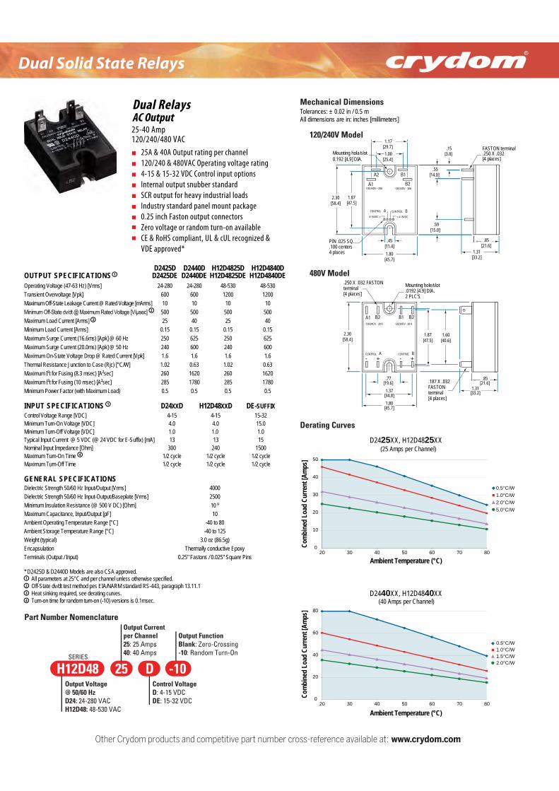
D2425XX, H12D4825XX
0
10
20
30
40
50
20 30 40 50 60 70 80
Ambient Temperature (°C)
Com
bine
d Lo
ad C
urre
nt [A
mps
]
0.5°C/W1.0°C/W2.0°C/W5.0°C/W
(25 Amps per Channel)
D2440XX, H12D4840XX
0
20
40
60
80
20 30 40 50 60 70 80
Com
bine
d Lo
ad C
urre
nt [A
mps
]
Ambient Temperature (°C)
0.5°C/W1.0°C/W1.5°C/W2.0°C/W
(40 Amps per Channel)
25A & 40A Output rating per channel120/240 & 480VAC Operating voltage rating4-15 & 15-32 VDC Control input optionsInternal output snubber standardSCR output for heavy industrial loadsIndustry standard panel mount package0.25 inch Faston output connectorsZero voltage or random turn-on availableCE & RoHS compliant, UL & cUL recognized &VDE approved*
25-40 Amp120/240/480 VAC
AC OutputDual Relays
Operating Voltage (47-63 Hz) [Vrms]Transient Overvoltage [Vpk]Maximum Off-State Leakage Current @ Rated Voltage [mArms]
Maximum Load Current [Arms]Minimum Load Current [Arms]Maximum Surge Current (16.6ms) [Apk] @ 60 Hz
Maximum On-State Voltage Drop @ Rated Current [Vpk]Thermal Resistance Junction to Case (Rjc) [°C/W]Maximum I²t for Fusing (8.3 msec) [A²sec]
Minimum Power Factor (with Maximum Load)
INPUT SPECIFICATIONS D24XXD H12D48XXD
24-2806001050025
0.15250
1.61.02260
0.5
D2425DD2425DE
24-2806001050040
0.15625
1.60.631620
0.5
D2440DD2440DE
48-53012001050025
0.15250
1.61.02260
0.5
H12D4825DH12D4825DE
48-53012001050040
0.15625
Maximum Surge Current (20.0ms) [Apk] @ 50 Hz 240 600 240 6001.60.631620
Maximum I²t for Fusing (10 msec) [A²sec] 285 1780 285 17800.5
H12D4840DH12D4840DE
51-451-4]CDV[ egnaR egatloV lortnoC0.40.4 ]CDV[ egatloV nO-nruT muminiM 0.10.1]CDV[ egatloV ffO-nruT muminiM
Typical Input Current @ 5 VDC (@ 24 VDC for E-Suffix) [mA] 13 13042003 ]mhO[ ecnadepmI tupnI lanimoN
elcyc 2/1elcyc 2/1emiT nO-nruT mumixaMelcyc 2/1elcyc 2/1emiT ffO-nruT mumixaM
DE-SUFFIX15-3215.01.015
15001/2 cycle1/2 cycle
GENERAL SPECIFICATIONS0004]smrV[ tuptuO/tupnI zH 06/05 htgnertS cirtceleiD
Minimum Insulation Resistance (@ 500 V DC) [Ohm] 10 9
01]Fp[ tuptuO/tupnI ,ecnaticapaC mumixaMAmbient Operating Temperature Range [°C]
All parameters at 25°C and per channel unless otherwise specified.* D2425D & D2440D Models are also CSA approved.
Off-State dv/dt test method pes EIA/NARM standard RS-443, paragraph 13.11.1Heat sinking required, see derating curves.Turn-on time for random turn-on (-10) versions is 0.1msec.
-40 to 80521 ot 04-]C°[ egnaR erutarepmeT egarotS tneibmA
)g5.68( zo 0.3)lacipyt( thgieWyxopE evitcudnoc yllamrehTnoitaluspacnE
sniP erauqS "520.0 / snotsaF "52.0)tupnI / tuptuO( slanimreT
4
3
2
1
4
1
OUTPUT SPECIFICATIONS 1
2
3
0052]smrV[ etalpesaB/tuptuO-tupnI zH 06/05 htgnertS cirtceleiD
120/240V Model
1.87[47.5]
.85[21.6]
1.31[33.2]
1.00[25.4]
1.17[29.7] FASTON terminal
.250 X .032[4 places]
PIN .025 SQ..100 centers4 places
Mounting hola/slot0.192 [4.9] DIA.
± 4-15VDC
CONTROL BCONTROL A4-15VDC ±
A1
A2 B1
B2120/24OV - 20A120/24OV - 20A
.15[3.8]
.59[15.0]
.45[11.4]
.55[14.0]
2.30[58.4]
1.80[45.7]
480V Model
.85[21.6]
1.31[33.2]
.77[19.6]1.37
[34.8]
1.87[47.5]
1.60[40.6]
Mounting hole/slot.0192 [4.9] DIA.2 PLC'S
120/24OV - 20 A120/24OV - 20 A
1.80
2.30[58.4]
- + - +
.250 X .032 FASTONterminal[4 places]
.187 X .032 FASTONterminal[4 places]
[45.7]
Mechanical DimensionsTolerances: ± 0.02 in / 0.5 mAll dimensions are in: inches [millimeters]
CONTROL BCONTROL A
A1 B2B1B2
Distributed by :
CAT/CR/ED/EN
© 2016 Crydom Inc., All Rights Reserved.
10/2016
Specifications are subject to change without prior notice.Crydom and the Crydom logo are registered trademarksof Crydom Inc.
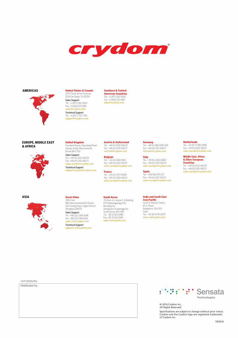
AMERICAS
EUROPE, MIDDLE EAST& AFRICA
ASIA
United States & Canada2475 Paseo de las Americas5014 San Diego, CA 92154
Sales Support
Technical Support
Great China30th FloorBM Intercontinental Biz Centre, 100 Yutong Road, JingAn DistrictShanghai 200070
Sales Support
Technical [email protected]
South Korea7th floor of U-space 2, A Building670 Daewangpangyo-RoBundang-GuSeongnam-Si Gyeonggi-DoSouth Korea, 463-400Tel.: +82 31 601 2088Fax: +82 31 601 [email protected]
United KingdomEverdene House, Deansleigh RoadWessex Fields, Bournemouth,Dorset BH7 7DU
Sales Support
Technical [email protected]
Germany
Spain
Austria & Switzerland
Fax : +44 (0) 1202 [email protected]
Belgium
Fax : +44 (0) 1202 [email protected]
France
Fax : +44 (0) 1202 [email protected]
Italy
Fax : +44 (0) 1202 [email protected]
Netherlands
Fax : +44 (0) 1202 [email protected]
Middle East, Africa& Other European Countries
Fax : +44 (0) 1202 [email protected]
Southern & Central American Countries
India and South East Asia PacificLevel 9, Raheja TowersM. G. RoadBangalore, 560 001IndiaTel.: +91 80 6792 [email protected]