for ballot june 29, 2018 addendum to api 16a,...
TRANSCRIPT

This document is not an API Standard; it is under consideration within an API technical committee but has not received all approvals required to become an API Standard. It shall not be reproduced or circulated or quoted, in whole or in part, outside of API committee activities except with the approval of the Chairman of the committee having jurisdiction and staff of the API Standards Department. Copyright API. All rights reserved.
Addendum to API 16A, 4th Edition - Annex H
FOR BALLOT June 29, 2018
Addendum to API 16A, 4th Edition
This is a proposed addendum to API 16A, 4th Edition. The scope of the proposed changes includes the addition of Annex H (attached) and Annex I System Assessment (attached) in its entirety as well as changes to the following sections (shown in red) in the existing 16A, 4th Edition document.
Supplement to 1 Scope with
“Annex H, specifies requirements for performance, design, materials, testing and inspection, welding, marking, handling, storing and shipping of drill-through equipment that meet the definition of high-pressure high-temperature (HPHT).
Drill-through equipment repair and remanufacturing is not in the scope of Annex H.”
Supplement Normative Reference 2 with
― API Specification 5L, Specification for Line Pipe, 45th Edition
― API Specification 17D, Design and Operation of Subsea Production Systems—Subsea
Wellhead and Tree Equipment, 2nd Edition
― API Specification 20A, Carbon Steel, Alloy Steel, Stainless Steel, and Nickel Base Alloy
castings for Use in the Petroleum and Natural Gas Industry
― API Specification 20B, Open Die Shaped Forgings for Use in the Petroleum and Natural Gas
Industry
― API Specification 20C, Closed Die Shaped Forgings for Use in the Petroleum and Natural Gas
Industry
― ASME BPVC Section VIII, Division 2, Rules for Construction of Pressure Vessels—Alternative
Rules
― ASME BPVC Section VIII, Division 3, Rules for Construction of Pressure Vessels—Alternative
Rules for Construction of High Pressure Vessels
― API Specification Q1, Specification for Quality Management System Requirements for
Manufacturing Organizations for the Petroleum and Natural Gas Industry
Supplement Terms and Definitions 3 with
3.1.X high-pressure high-temperature HPHT
rated pressure is greater than 103.5 MPa (15,000 psia) and/or the rated temperature is greater than 177°C (350°F).

This document is not an API Standard; it is under consideration within an API technical committee but has not received all approvals required to become an API Standard. It shall not be reproduced or circulated or quoted, in whole or in part, outside of API committee activities except with the approval of the Chairman of the committee having jurisdiction and staff of the API Standards Department. Copyright API. All rights reserved.
Addendum to API 16A, 4th Edition - Annex H
3.1.X essential variable
an attribute specified in the material specification, which if changed, would likely result in considerable degradation of the material properties (fracture toughness, FCGR, or S-N fatigue life) in the operating environments.
3.1.X Inspection and Test Plan ITP Plan that specifies the required production processes and associated critical control points (i.e., scheduled inspection / verification points, e.g., hold, witness, monitor, and document review), which are required to be performed by the manufacturer’s quality control inspector(s) and (if required) the purchaser’s third party inspector (TPI) and/or other interested party (e.g. classification society) NOTE References to Quality Plans (QP) refer to a different type document. An ITP is not a Quality Plan, see definition of Quality Plan 3.1.X.
3.1.X Maximum Load Condition MLC All relevant combinations of: pressure (internal and external), external loads (tension, compression, shear, bending, and torsion), and thermal loads (considering both minimum and maximum temperature. 3.1.X quality plan Document or several documents that together specify the quality standards, practices and procedures and associated resources, and how the manufacturer’s quality management system is applied to a specific product, project, or contract / purchase order NOTE Quality Plans in the context of this document do not mean “Inspection and Test Plan” (ITP). An ITP may be an Attachment or an Appendix to a Quality Plan or a stand-alone document. See definition of ITP 3.1.X.
3.1.X raw material Material, which has not received any form of value added operations intended to create functional parts; such as: weld assembly, cladding, hard facing, finish machining etc. NOTE Typical examples of raw material are rough machined and heat treated forgings, tubular components in accordance with industry standards, rolled products, heat-treated castings, etc. 3.1.X production lot Defined quantity of product manufactured under conditions that are considered uniform
Supplement Acronyms and Abbreviations 3.2 with
BPVC Boiler and Pressure Vessel Code (ASME)
CP cathodic protection
CS carbon steel
CTOD crack tip opening displacement
CVN Charpy V-notch
EAC environmentally assisted cracking

This document is not an API Standard; it is under consideration within an API technical committee but has not received all approvals required to become an API Standard. It shall not be reproduced or circulated or quoted, in whole or in part, outside of API committee activities except with the approval of the Chairman of the committee having jurisdiction and staff of the API Standards Department. Copyright API. All rights reserved.
Addendum to API 16A, 4th Edition - Annex H
FCGR fatigue crack growth rate
FM fracture mechanics
LAS low alloy steel
LRFD load and resistance factor design
ppm parts per million
PoD probability of detection
RWP rated working pressure
S-N stress-cycle curves
YS yield strength
UTS ultimate tensile strength
Supplement Bibliography with
– API Technical Report TR6J1, Elastomer Life Estimation Testing Procedures
– API Technical Report 1PER15K-1, Protocol for Verification and Validation of High-pressure High-temperature Equipment
– API Technical Report TR6MET, Metallic Material Limits for Wellhead Equipment Used in High Temperature for API 6A and 17D Applications
– ASME BPVC Section II, Materials
– ASNT CP-189, Qualification and Certification of Nondestructive Testing Personnel
– ASTM A388, Standard Practice for Ultrasonic Examination of Steel Forgings
– ASTM D1415, Standard Test Method for Rubber Property-International Hardness
– ASTM D6147, Standard Test Method for Vulcanized Rubber and Thermoplastic Elastomer—Determination of Force Decay (Stress Relaxation) in Compression
– ASTM E8, Standard Test Methods for Tension Testing of Metallic Materials
– ASTM E21, Standard Test Methods for Elevated Temperature Tension Tests of Metallic Materials
– ASTM E399, Standard Test Method for Linear-Elastic Plane-Strain Fracture Toughness KIC of Metallic Materials
– ASTM E466, Standard Practice for Conducting Force Controlled Constant Amplitude Axial Fatigue Tests of Metallic Materials
– ASTM E606, Standard Practice for Strain-Controlled Fatigue Testing
– ASTM E647, Standard Test Method for Measurement of Fatigue Crack Growth Rates
– ASTM E1681, Standard Test Method for Determining Threshold Stress Intensity Factor for Environment-Assisted Cracking of Metallic Materials
– ASTM E1820, Standard Test Method for Measurement of Fracture Toughness

This document is not an API Standard; it is under consideration within an API technical committee but has not received all approvals required to become an API Standard. It shall not be reproduced or circulated or quoted, in whole or in part, outside of API committee activities except with the approval of the Chairman of the committee having jurisdiction and staff of the API Standards Department. Copyright API. All rights reserved.
Addendum to API 16A, 4th Edition - Annex H
– BS 7608, Guide to fatigue design and assessments of steel products
– BS 7910, Guide to methods for assessing the acceptability of flaws in metallic structures
– DNVGL-RP-C203, Fatigue Design of Offshore Steel Structures
– ISO 3384-1, Rubber, vulcanized or thermoplastic—Determination of stress relaxation in compression Part 1: Testing at constant temperature
– ISO 13879, Petroleum and Natural Gas Industries—Content and Drafting of a Functional Specification
– ISO 13880, Petroleum and Natural Gas Industries—Content and Drafting of a Technical Specification
– ISO 23936-1, Petroleum, petrochemical and natural gas industries — Non-metallic materials in contact with media related to oil and gas production — Part 1: Thermoplastics
– ISO 23936-2, Petroleum, petrochemical and natural gas industries—Non-metallic materials in contact with media related to oil and gas production—Part 2: Elastomers
– NACE TM0198, Slow Strain Rate Test Method for Screening Corrosion-Resistant Alloys for Stress Corrosion Cracking in Sour Oilfield Service

This document is not an API Standard; it is under consideration within an API technical committee but has not received all approvals required to become an API Standard. It shall not be reproduced or circulated or quoted, in whole or in part, outside of API committee activities except with the approval of the Chairman of the committee having jurisdiction and staff of the API Standards Department. Copyright API. All rights reserved.
Addendum to API 16A, 4th Edition - Annex H
Supplement API 16A, 4th Editions with the following:
Add Requirement to Section 4.2.1: Rated Working Pressure, Table 2-Equipment working pressure
“For equipment with rated working pressures of 138 MPa (20,000), 172 MPa (25,000 psi) and 206.8 MPa (30,000 psi) on surface the requirements in Annex H shall apply.”
Add Requirement to Section 4.2.2 Temperature Ratings before Table 3:
“Equipment classification T-75/400; T-20/400; T-0/400 and T-75/450; T-20/450; T-0/450 shall be designed for metallic parts to meet the temperature requirements in Annex H.”
Add Requirement to Section 4.2.2 Temperature Ratings, Table 3
Edit the table to add classification: T-75/400; T-20/400; T-0/400 and T-75/450; T-20/450; T-0/450.
Add an informative section, 4.3.14 to read:
“4.3.14 – Equipment in High Pressure High Temperature (HPHT) Application
NOTE: Design verification requirements for equipment in for use in HPHT application are found in Annex H Section H.5.”
Add a section, 4.4.9 to read:
“4.4.9 – Equipment in High Pressure High Temperature (HPHT) Application
For HPHT equipment, design requirements in Annex H, Section H.5 shall apply.”
Add a section, 4.5.7 to read:
“4.5.7 - Equipment in High Pressure High Temperature (HPHT) Application
Design validation requirements for HPHT equipment shall meet the requirements in Annex H, Section H.7”
Add a section, 4.7.4 to read:
“4.7.4 - Equipment in High Pressure High Temperature (HPHT) Application
For HPHT equipment, the design validation requirements Annex H Section H.7 shall apply.”
Modify Table in section, 5.3.4.2 to read:
5.3.4.2 Impact Testing: Modify the table to remove the High Temp / in the first column.
Add a section, 5.5 to read:
“5.5 Materials for Drill-Through Equipment in High Pressure High Temperature (HPHT) Application
Materials selection and qualification requirements for construction of API 16A drill-through equipment used in HPHT application shall meet Annex H, section H.4”

This document is not an API Standard; it is under consideration within an API technical committee but has not received all approvals required to become an API Standard. It shall not be reproduced or circulated or quoted, in whole or in part, outside of API committee activities except with the approval of the Chairman of the committee having jurisdiction and staff of the API Standards Department. Copyright API. All rights reserved.
Addendum to API 16A, 4th Edition - Annex H
Add a section, 7.5.7.8.7 to read:
“7.5.7.8.7 - High Pressure High Temperature (HPHT) Equipment
For HPHT equipment the requirements in Annex H Section H.6 shall apply.”
Add a sentence to section 7.6.1 to read:
“For HPHT equipment the requirements in Annex H Section H.6 shall apply.”

This document is not an API Standard; it is under consideration within an API technical committee but has not received all approvals required to become an API Standard. It shall not be reproduced or circulated or quoted, in whole or in part, outside of API committee activities except with the approval of the Chairman of the committee having jurisdiction and staff of the API Standards Department. Copyright API. All rights reserved.
7
Annex H (Normative)
Drill-through Equipment in High-pressure High-temperature Application
H.1 Applicability of Drill-through High-pressure High-temperature Annex
This Annex shall apply to the performance, design, materials, testing and inspection, welding, marking,
handling, storing and shipping of drill-through equipment that meet the definition of high-pressure high-
temperature (HP/HT).
NOTE 1: HP/HT application is defined as the maximum anticipated surface pressure greater than 103.5
MPa (15,000 psi) and/or the flowing temperature is greater than 177°C (350°F).
The service conditions in this Annex shall apply to pressure ratings to 206.8 MPa (30,000 psi) and
temperature ratings to 232°C (450°F).
NOTE 2: Drill-through equipment repair and remanufacturing is not in the scope of this Annex. Refer to
API 16AR, Standard for Repair and Remanufacturing of Drill-through Equipment for repair and
remanufacturing requirements.
H.2 Basis of Design / Design Philosophy
H.2.1 General
Design philosophies for drill-through equipment in HP/HT application are:
― To protect people, environment and assets, industry standards and guidance are required to ensure
the proper design and performance assurance of equipment in HP/HT application
― The equipment is designed to prevent discharge of hydrocarbons to the environment.
― The drill-through equipment is not designed to serve as permanently installed well control equipment.
An inspection frequency and methodology shall be defined to ensure equipment cyclic load capacity is
not exceeded.
― Design analysis is based on proper usage and maintenance of equipment, and does not include
situations involving gross negligence or willful misconduct.
― Risk assessment should be performed to identify failure modes affecting the system/sub-systems and
assembly/component and, when appropriate, risk mitigation measures should be implemented.
NOTE: Refer to Annex I for guidance between system/sub-system and assembly/component relationship.
H.2.2 Pressure - Temperature Category/combinations
For the purposes of this document, high-pressure and high-temperature applications shall be categorized, based on the following definitions:
― HP : High-pressure: >103.4 MPa (>15,000 psi)
― HT : High-temperature: >177°C - 232°C (>350°F - 450°F)
― SP : Standard-pressure: ≤103.4 MPa (≤15,000 psi)
― ST : Standard-temperature: ≤177°C (≤350°F)

This document is not an API Standard; it is under consideration within an API technical committee but has not received all approvals required to become an API Standard. It shall not be reproduced or circulated or quoted, in whole or in part, outside of API committee activities except with the approval of the Chairman of the committee having jurisdiction and staff of the API Standards Department. Copyright API. All rights reserved.
8
NOTE: The pressure-temperature categories are represented in Figure H.1.
Figure H.1―Pressure-Temperature Category
H.2.3 Basis of Design
The qualification of drill-through equipment in HP/HT application should be based upon an assessment of
all applicable ratings of the equipment. The qualification should take into account the anticipated
environment during the equipment's service life for protection against foreseeable failure modes for the
equipment
Generally, this is completed by calculating the maximum capacity of the equipment in the environment and
with consideration to the design or safety margins for the normal, extreme (planned or unplanned) and
survival (unplanned) loading conditions. This information should be included in a risk management plan for
the intended operation.
NOTE 1: The objective of the equipment technology qualification process is to ensure that the equipment
is fit-for-service. The qualification process shall ensure that the equipment is capable of meeting the ratings
for which it has been designed.
NOTE 2: General product development process is outlined in Figure H.2.

This document is not an API Standard; it is under consideration within an API technical committee but has not received all approvals required to become an API Standard. It shall not be reproduced or circulated or quoted, in whole or in part, outside of API committee activities except with the approval of the Chairman of the committee having jurisdiction and staff of the API Standards Department. Copyright API. All rights reserved.
9
Figure H.2―Product Development Process
NOTE 3: There are three principles that are integral to support drill-through equipment in HP/HT service
qualification process:
― The design process (design verification and design validation)
― The material selection incorporated into the design, and
― The manufacturing process plan including quality plan
H.2.4 Functional Specifications
General
Equipment functional specifications (FS) should be defined by the equipment end-user/operator. The
equipment end-user/operator should provide a complete functional specification to include operational loads,
external loads, fluid properties and environmental conditions as the basis of design for the equipment using a
life-cycle approach with sufficient details for the manufacturer to conduct the design analysis or design
verification. The functional design requirements shall include all foreseeable mechanical, hydraulic, chemical,
and thermal loads that may be applied to the equipment through its life-cycle.
NOTE: Guidance on developing a functional specification is found in ISO 13879.
Loads Identification
Functional specification shall define all applicable environmental conditions and operational, external and test loads, or combination thereof. These loads shall include, but are not limited to, the following:
1) Environmental Conditions:
2) Operational Loads

This document is not an API Standard; it is under consideration within an API technical committee but has not received all approvals required to become an API Standard. It shall not be reproduced or circulated or quoted, in whole or in part, outside of API committee activities except with the approval of the Chairman of the committee having jurisdiction and staff of the API Standards Department. Copyright API. All rights reserved.
10
― Pressure / Temperature Loads (wellhead)
3) External Loads (quasi-static and cyclic)
― Tension
― Bending
4) Operational Cyclic Loads
― Cyclic loads (bending, tension, shear, etc.)
― Operational pressure/temperature cycles
5) Extreme and Survival Events
Note: Reasonable loads should be evaluated and considered.
Possible combinations of various design criteria should be specified in the form of a desired operating
envelope for the product if applicable.
Where functional specifications are not available, the manufacturer should provide a design technical
specification for the equipment based on experience or documented capabilities of existing equipment for
review and acceptance by the end-user/operator.
NOTE: The equipment functional specification may be derived through a system design process that
evaluates the interactions and load transferred from the sub-system to the component/assembly. Guidance
to a system design process is provided in Annex I, System Assessment.
H.2.5 Technical Specifications
General
The manufacturer shall document the technical specifications (TS) for the drill-through equipment.
The Product Realization of API Q1 addresses the design and documentation process and shall be followed
for drill-though equipment in HP/HT application.
The equipment technical specifications shall comprise, at a minimum, the elements of H.2.5.2 through
H.2.5.6.
NOTE 1: The design technical specification is a document that defines the technical requirements to be
fulfilled by the product, process or service in order to conform to the functional specification. Guidance on
developing a technical specification is found in ISO 13880
Risk Assessment and Techniques
Risk assessment should be performed on 16A HP/HT equipment to identify failure modes resulting hazards
affecting the equipment.
NOTE: Examples of typical risk assessment and/or hazard identification techniques are:
― Hazard Identification (HAZID) is a general term used to describe an exercise whose goal is to identify
hazards and associated events that have the potential to result in an undesirable consequence.
― Hazard and Operability (HAZOP) analysis technique uses specific or special guidewords to prompt an
experienced group of individuals to identify potential hazards or operability concerns relating to pieces
of equipment or systems.
― Failure Modes and Effects Analysis (FMEA) technique may be deployed to 1) identify all foreseeable
potential failure modes of the component or system and 2) consider how the failure mode of each
system component may result in system performance problems.

This document is not an API Standard; it is under consideration within an API technical committee but has not received all approvals required to become an API Standard. It shall not be reproduced or circulated or quoted, in whole or in part, outside of API committee activities except with the approval of the Chairman of the committee having jurisdiction and staff of the API Standards Department. Copyright API. All rights reserved.
11
― Failure Modes, Effects and Criticality Analysis (FMECA) should be conducted by the equipment
manufacturer, as applicable or necessary; to identify the failure modes of the equipment under
anticipated service conditions. The scope of the identified failure modes shall be reviewed as part of
the manufacturer's validation program to determine if additional tests are warranted to validate
performance or mitigate the probability of failure.
NOTE: Additional and/or specific validation testing, may be further defined and agreed upon between
the equipment end-user/operator and the manufacturer to validate failure mode(s) warranted by project-
specific operational FMECA that identifies failure modes resulting from a special use, unique
environments, or severe service requirements
Design Verification
General
Design verification shall be performed for drill-through equipment for conformance to functional design
specifications (refer to H.3 for detailed requirements).
Protection Against Known Failure Modes
Design verification shall be performed to verify protection against foreseeable failure modes in drill-through
equipment in accordance with recognized acceptance criteria, i.e. design code/standard, manufacturer’s
design guidelines, etc.
NOTE: Foreseeable failure modes may include, but are not limited to:
― global plastic collapse;
― local strain limit damage;
― serviceability (leakage);
― excessive deformation;
― ratcheting effects;
― plastic collapse under hydrostatic test condition;
― fatigue (life-cycle estimation)
An additional objective for design verification can be the establishing of equipment external loads capacity.
Design Verification Methodology
The selection of the design methodology; e.g. linear-elastic, elastic-perfectly plastic, or elastic-plastic, shall
be at the discretion of the equipment designer and equipment type indicated in H.3.4 and shall be used
consistent with the requirements of the applicable API specifications or standards
Material Selection and Qualification
General
The manufacturer shall ensure the material selection conforms to relevant industry standards and
compliance with regulatory HP/HT guidance. The manufacturer shall define the material properties
necessary for design verification purposes to ensure the equipment is fit-for-service. Refer to H.4 for
detailed requirements.
The manufacturer shall define the sources for necessary material properties. Sources may be existing
industry data or manufacturer proposed material testing.
This document is not an API Standard; it is under consideration within an API technical committee but has not received all approvals required to become an API Standard. It shall not be reproduced or circulated or quoted, in whole or in part, outside of API committee activities except with the approval of the Chairman of the committee having jurisdiction and staff of the API Standards Department. Copyright API. All rights reserved.
12
Material Selection for the Intended Environment
The material selections for HP/HT applications shall account for the service conditions and environmental
conditions. Environmental conditions can have significant effects on material properties. Environmental effects
on materials shall be evaluated for input into the design verification analyses. Both thermal and fluids
degradation effects shall be identified for each material within the drill-through equipment, as applicable.
Material Characterization/testing
The procedures to define the material characterization program for sacrificial and/or first article qualification
shall be developed.
Correlation between the material properties from sacrificial and/or first article qualification and the
production testing during materials manufacturing should be defined and agreed upon between the
equipment end-user/operator and the manufacturer.
Design Validation
Design validation shall be performed to establish that the equipment demonstrates the mechanical integrity
and functionality/operability required by the functional specifications. Refer to H.5 for detailed
requirements.
FMEA/FMECA shall be conducted by the manufacturer with input from the end-user/operator, as applicable
or necessary; to identify the failure modes of the equipment under anticipated service conditions.
The range of the identified failure modes shall be reviewed as part of the manufacturer's validation
program to determine if additional tests are warranted to validate performance or mitigate the probability of
failure.
Manufacturing Process
Manufacturing process specifications shall be developed by the manufacturer that implement production of
the qualified design and shall include a quality plan for the manufacturing process.
Drill-through equipment shall be manufactured in accordance with an inspection and test plan (ITP) that
specifies the processes of the quality management system (including product realization processes and the
resources to be applied to the product.
H.3 Design Verification
H.3.1 General
For verification purposes, this Annex makes reference to the design verification methods of ASME BPVC
Section VIII, Div. 2 (ASME VIII-2) and Section VIII, Div. 3 (ASME VIII-3). For these methods to be valid, the
designer shall ensure that the material properties used in the analyses are minimum design material
specifications consistent with the material requirements in H.4. All geometry except bolting shall be
analyzed at the nominal dimensional condition.
H.3.2 Loading Conditions
The loading conditions for the verification analysis shall be obtained from the technical specification. See
Section H.2.4.2 for the loads to evaluate.
NOTE: Load categories are segregated by severity and have varying allowable stresses applied during the
design and verification process.
The loads as defined shall be categorized as Normal, Extreme, and Survival according to the following
categorization.

This document is not an API Standard; it is under consideration within an API technical committee but has not received all approvals required to become an API Standard. It shall not be reproduced or circulated or quoted, in whole or in part, outside of API committee activities except with the approval of the Chairman of the committee having jurisdiction and staff of the API Standards Department. Copyright API. All rights reserved.
13
― Normal (also serviceability limit state) – a regularly expected loading condition in which equipment is
required to survive without damage and operate as intended.
― Extreme (also, ultimate limit state) – extreme conditions include the unavoidable but predictable load
conditions due the environmental and operating scenarios. The subsequent use of equipment
subjected to extreme loadings requires inspection or other evaluation processes to determine if it is fit-
for-service for continued operation. Wellbore pressure integrity is required at extreme loadings. Drill-
through connector unlock and disconnect functionality is required after extreme loadings.
― Survival (also, accidental limit state) – a load condition more severe than an extreme event in which
equipment is required to survive. The subsequent use of equipment subjected to survival loadings
requires inspection or other evaluation processes to consider if it is fit-for-service for continued
operation. Wellbore pressure integrity is required at survival loadings. Drill-through connector unlock
and disconnect functionality is required after survival loadings.
The pressure rating shall not be increased above the nominal rated working pressure of the equipment for
the normal, extreme and survival load cases.
H.3.3 Load Descriptions
General
Table 5.2 of ASME VIII-2 and Table KD-230.2 of ASME VIII-3 provide descriptions of the loads that are
analyzed using these methods. These loads may not directly correspond to the loadings required to be
analyzed for the drill-through equipment. The following is the correlation between loads typically
experienced in the oil and gas equipment and loads identified in ASME VIII-2 and ASME VIII-3.
𝑃 is the internal or external, specified design pressure;
𝑃𝑇 is the hydrostatic body test pressure;
𝐷 is the suspension or external loads (i.e. casing loads, external riser or piping loads,
installation loads [running], etc.) for normal, extreme and survival conditions (DNORMAL,
DEXTREME, DSURVIVAL, respectively);
𝐿 is the fluid dynamic loading (i.e. slugging, water hammer, flow induced vibration, wave
and current loading, vortex induced vibration [VIV], etc.);
𝑇 is the self-restraining loads (i.e. thermal loads, applied displacements). This load case
does not typically affect the collapse load, but should be considered in cases where
elastic follow-up causes stresses that do not relax sufficiently to redistribute the load
without excessive deformation:
𝑊𝐴 is the assembly loads (e.g. bolt preloads, shrink-fit, preload, etc.)
Maximum Load Condition
The various combinations of MLC shall be used to define the capacity of the equipment in normal, extreme and survival conditions via the application of the appropriate load factors in Table H.2 in the verification analysis.
H.3.4 Analysis Principles
When linear-elastic analysis is used, the analysis shall be checked to ensure the method is still valid according to the requirements in Section H.3.5.2.1. Alternatively, it shall be acceptable for equipment to be verified with elastic-plastic methods according to ASME VIII-2 or ASME VIII-3
Linear-elastic analysis shall be acceptable for RWP above 138 MPa (20,000 psi) if the analysis is checked to ensure the method is still valid according to the requirements in Section H.3.5.2.1.

This document is not an API Standard; it is under consideration within an API technical committee but has not received all approvals required to become an API Standard. It shall not be reproduced or circulated or quoted, in whole or in part, outside of API committee activities except with the approval of the Chairman of the committee having jurisdiction and staff of the API Standards Department. Copyright API. All rights reserved.
14
All components evaluated in an analysis shall have the same type of material model, except as specified below.
For a linear-elastic analysis, all components shall have linear elastic material properties (excluding gaskets and seals).
For an elastic-plastic analysis, all components shall have elastic-plastic material properties, except where permitted, e.g. bolting per H.3.6.8. and the paragraph in this section below.
In summary, one of the two (2) analytical verification procedures shall be applied to HPHT drill-through designs, shown in Table H.1.
Table H.1 – Analytical Verification Procedures
Linear-Elastic Analysis (According to API 6X) Elastic-Plastic Analysis (ASME VIII-2 or ASME VIII-3)
Limit of applicability of LE analysis shall be checked according to H.3.5.2.1.
Acceptable for all pressures
Each failure mode assessed in the analysis (i.e. global plastic collapse, local failure, serviceability, etc.)
shall consistently apply the same analytical verification procedure (e.g., linear-elastic, ASME VIII-2 elastic-
plastic or ASME VIII-3 elastic-plastic) for each failure mode.
Material properties shall be de-rated at elevated temperature, when applicable.
Thermal stresses and strains due to temperature distribution shall be assessed for ratcheting, fatigue, and
serviceability elastic-plastic analyses.
Linear-elastic material properties shall be acceptable for rams, ram shafts, and bolting for all pressure
ratings. Limit of linear elastic applicability (H.3.5.2.1) shall not be checked for these components.
NOTE 1: Traditionally, the standard practice relies on the verification methodologies from ASME BPVC Section VIII to provide design verification guidance when the equipment’s functional requirements go beyond the defined boundaries of the API specifications/standards.
NOTE 2: This document recognizes that traditional linear-elastic analysis in the existing API 6X
specification and within the scope of the governing standards have produced field-proven designs
NOTE 3: Temperature may be assumed to be uniform at the elevated temperature, or may be calculated
by thermal analysis. Refer to H.4 of this Annex for further details.
H.3.5 Design Verification Procedures
General
Design verification shall be performed to confirm that drill-through equipment design is conforms to its
functional specifications and serviceability criteria, and the equipment has adequate protection against
failure modes identified below:
1) Global plastic collapse
2) Local failure due to excessive strain (local strain limit damage)
3) Serviceability (leakage, excessive deformation)
4) Ratcheting effects
5) Plastic collapse under the hydrostatic test condition
This document is not an API Standard; it is under consideration within an API technical committee but has not received all approvals required to become an API Standard. It shall not be reproduced or circulated or quoted, in whole or in part, outside of API committee activities except with the approval of the Chairman of the committee having jurisdiction and staff of the API Standards Department. Copyright API. All rights reserved.
15
6) Fatigue (life cycle estimation)
When evaluating drill-through equipment, all parts in the load path being considered shall be evaluated in
the analysis. Once the component has been verified against the above failure modes, a capacity chart
(when applicable) shall be developed to show the capacity of the component under combined loadings.
For the design verification analysis, the material design minimum tensile properties (yield strength and
ultimate tensile strength) shall be de-rated due to the design temperature, when applicable. Temperature
may assumed to be uniform at the elevated temperature, or may be calculated by thermal analysis. Thermal
stresses and strains due to temperature distribution shall be assessed for ratcheting, fatigue, and
serviceability elastic-plastic analyses.
Global Plastic Collapse
Linear-Elastic Analysis
The applicable loads shall be applied at the maximum load condition (MLC). Stress linearization shall be
used and Stress Classification Lines (SCLs) shall be created for areas of high stress and concern.
Elastic-plastic analysis methods may be considered for thick-wall (“R/t ≤ 4” or “Do/Di ≥ 1.25”) pressure-
containing equipment analysis. Elastic-plastic analysis methods shall be used where calculated stresses
are above yield over a through thickness dimension which is more than five percent of the wall thickness.
NOTE 1: API 6X and applicable sections of ASME VIII-2 specify linear-elastic analysis for global plastic
collapse load
NOTE 2: The designer is cautioned to ensure appropriate use of the linear-elastic analysis methodology,
as this approach has the potential for non-conservative results from thick-wall stress distribution theory,
and/or stress categorization difficulties due to complex geometry associated with drill-through equipment.
NOTE 3: In either of these cases, linear-elastic analysis may give a non-conservative result.
Limit-Load Analysis1
For rated working pressures of 103.5 MPa (15,000 psi) or lower, it shall be alternatively acceptable to
perform a limit-load analysis to determine fitness for service against global plastic collapse. A limit-load
analysis shall comply with the criteria of ASME VIII-2 Paragraph 5.2.3. When performing a limit-load
analysis, the load factor shall be applied to the MLC; all loads shall be applied with the load factor
appropriate for the normal/extreme/survival condition.
Elastic-Plastic Analysis
The maximum allowable working load shall be verified by applying the applicable load factor to the internal
or external pressure, hydrostatic head loads and external loads to verify that these loads do not exceed the
component’s plastic collapse load (load at which unbounded plastic deformation occurs).
The elastic-plastic analysis, with the applicable load factor, shall comply with the global plastic criteria of
ASME VIII-2 Paragraph 5.2.4 or ASME VIII-3 Article KD-231. When performing an elastic-plastic collapse
analysis, the load factor shall be applied to the MLC; all loads shall be applied with the load factor
appropriate for the normal/extreme/survival condition.
NOTE: Elastic-plastic analysis provides increased accuracy in the assessment of protection against global
plastic collapse of a component as compared to the linear-elastic analysis method, as the elastic-plastic
stress analysis simulates the component’s actual material behavior under the applied loadings
1 Kalnins, Arturs; Welding Research Bulletin 464, Guidelines for Sizing of Vessels by Limit Analysis, Welding Research Council, Inc. 3 Park Avenue, New York, NY 10016-5902

This document is not an API Standard; it is under consideration within an API technical committee but has not received all approvals required to become an API Standard. It shall not be reproduced or circulated or quoted, in whole or in part, outside of API committee activities except with the approval of the Chairman of the committee having jurisdiction and staff of the API Standards Department. Copyright API. All rights reserved.
16
Local Strain Limit
Linear-Elastic Analysis
The linear-elastic analysis criteria to prevent local failure at peak strain locations (i.e. structural
discontinuities, notches, etc.) or the triaxial-stress verification within the pressure-containing equipment
shall be as defined in ASME VIII-2 Paragraph 5.3.2, where S = 2/3SY.
Elastic-Plastic Analysis
The elastic-plastic analytical verification procedures shall evaluate the limiting triaxial-strain at peak strain
locations (i.e. structural discontinuities, notches, etc.) within the pressure-containing equipment.
The elastic-plastic local strain analysis shall comply with ASME VIII-2 Paragraph 5.3.3 or ASME VIII-3
Article KD-232.
Serviceability
Linear-Elastic Analysis
It shall be acceptable to assess serviceability using linear-elastic methods so long as the calculated
stresses do not exceed the yield stress over a through wall thickness dimension which is less than or equal
to five percent of the wall thickness.
NOTE: Examples of serviceability criteria are provided in H.3.5.4.2.
Elastic-Plastic Analysis
Serviceability criteria that limit the potential for unsatisfactory performance shall be analyzed when subject
to the hydrostatic test and design loads. Examples of serviceability criteria are limits on the rotation of a
mating flange pair to avoid possible flange leakage concerns, and limits on part deflection that may cause
operational concerns.
The effect of deformation of the component on service performance shall be evaluated at the design load
combinations after the accumulated strains due to hydrostatic test are assessed.
NOTE: The plastic collapse criteria may be satisfied but the component may have excessive deformation
at the derived design conditions.
In the case of excessive deformation, the design loads shall be reduced based on a serviceability criterion.
Examples of some of the considerations in this evaluation are the effect of deformation and deflection on:
― gasket mating faces
― seal locations
― misalignment of locking segments
Ratcheting
Linear-Elastic Analysis
The linear-elastic analysis criteria to prevent ratcheting of the pressure-containing component shall be
evaluated according to ASME VIII-2 Paragraph 5.5.6.
Elastic-Plastic Analysis
Material properties for the elastic-plastic ratcheting assessment shall be elastic-perfectly-plastic input at the
material minimum specified yield strength. The ratcheting assessment shall be performed and comply with
ASME VIII-2 Paragraph 5.5.7 or ASME VIII-3 Article KD-234.

This document is not an API Standard; it is under consideration within an API technical committee but has not received all approvals required to become an API Standard. It shall not be reproduced or circulated or quoted, in whole or in part, outside of API committee activities except with the approval of the Chairman of the committee having jurisdiction and staff of the API Standards Department. Copyright API. All rights reserved.
17
A ratcheting analysis shall be performed for the normal load case as well as the extreme load case. Material
yield strength shall be de-rated due to the design temperature, when applicable..
Hydrostatic Body Pressure Test
Linear-elastic Analysis
The linear-elastic analysis criteria to prevent failure through of the component at hydrostatic test conditions
are defined in API 6X, 4.2. The linear-elastic analysis criteria shall be applied at the hydrostatic body test
pressure.
Elastic-plastic Analysis
Elastic-plastic stress analysis shall be used to ensure the pressure vessel does not exhibit plastic collapse
under the hydrostatic body test pressure for the elastic-plastic analytical verification procedure. The elastic-
plastic hydrostatic body test condition stress analysis shall be performed in accordance with the applicable
sections of ASME VIII-2 or VIII-3.
Fatigue
General
Subsequent to the design verification for pressure containment integrity, drill-through equipment that may
undergo cyclic operations (i.e. pressure, temperature, external loads, etc.) shall be subjected to a fatigue
screening to determine if fatigue assessment is necessary to calculate its life-cycle estimation for
compliance with its functional specifications.
A fatigue screening shall not be required if a fatigue analysis is performed.
Fatigue Screening
Evaluation of the pressure-containing component using the fatigue screening methods of this document
determines if fatigue analysis is required to calculate its life-cycle characteristics for compliance with the
functional specifications. If fatigue analysis is not required based on the screening criteria, this shall be
documented within the manufacturer’s technical specifications with technical justification.
The provisions of ASME VIII-2 Paragraph 5.5.2 shall be used as the fatigue screening process, based on
the material’s specified minimum tensile strength, full-range pressure/temperature cycles, and operating
pressure/temperature cycle ranges, as applicable. Successful experience over a sufficient time frame for
similar equipment subject to a similar loading histogram may be used as the basis for fatigue screening.
Fatigue screening shall be evaluated based on a detailed load histogram, which shall be defined as part of
the functional specifications.
If the drill-through equipment design does not satisfy the fatigue screening criteria in ASME VIII-2 Paragraph
5.5.2, then a fatigue assessment through the S-N or Fracture Mechanics (FM) design methods shall be
performed.
When using ASME VIII-2, the S-N design is provided as the basis for fatigue assessment. However, the
designer may elect to use the FM design as an alternative.
When using ASME VIII-3, the FM design shall be used for a fatigue assessment.
Replaceable equipment may satisfy the fatigue assessment by validation testing to the required
replacement interval.
Alternating Stress (or Strain) Analysis (S-N Analysis)
The S-N design method for fatigue assessment shall be based on the methodology prescribed in ASME
VIII-2 Paragraph 5.5, ASME VIII-3 Article KD-3, DNVGL-RP-C203, or BS 7608. The material fatigue
properties and/or data shall be representative of operating conditions.

This document is not an API Standard; it is under consideration within an API technical committee but has not received all approvals required to become an API Standard. It shall not be reproduced or circulated or quoted, in whole or in part, outside of API committee activities except with the approval of the Chairman of the committee having jurisdiction and staff of the API Standards Department. Copyright API. All rights reserved.
18
One code of practice for the fatigue analysis shall be used.
S-N curves used shall consider welded specimens/geometry as well as applicable environmental
conditions. The S-N curves used shall be based on test specimens from the same class of materials and
tested in the same environment conditions (i.e. air, salt water immersion, salt air/salt water spray, high
humidity, H2S, caustic agents, etc.) as expected service conditions. Otherwise, results shall be modified by
using validated correction reduction factors to account for any degradation in performance or design life.
Fatigue-sensitive locations (i.e. structural discontinuities, notches, etc.) shall be identified and fatigue
analyses performed on these locations. S-N curves of test specimens with similar representative features
may be used, following the procedures in prescribed ASME or DNV standards. Stress intensification factors
may be computed and used with S-N curves of smooth samples to calculate fatigue life. For welded
structures, the structural-stress method for fatigue analysis feature S-N curves of welded
specimens/geometries and is found in ASME VIII-2, ASME VIII-3, BS 7608 and DNVGL-RP-C203.
The result of the fatigue analysis is a calculated number of design cycles, Nf, for each type of operating
cycle, and a calculated cumulative number of allowable cycles when more than one type of operating cycle
exists. The accumulated fatigue damage shall be based on linear cumulative damage, Palmgren-Miner
rule, as defined in ASME VIII-2, ASME VIII-3, BS 7608 and DNVGL-RP-C203.
NOTE: The designer is cautioned to respect the limitations of usage of the various methods. For example,
ASME VIII-3 does not permit the structural-stress method for pressurized areas.
Fracture Mechanics Analysis
The Fracture Mechanics (FM) design method for fatigue assessment shall be based on ASME VIII-3 Article
KD-4, API 579-1/ASME FFS-1 Part 9 and Annex F, or BS 7910. H.4 of this Annex provides guidance on
establishing the fatigue crack growth data associated with Fracture Mechanics analysis.
Where life-cycle estimation represents the number of load cycles to failure based on FM design, the
allowable cycles for the intended service life shall be based on the critical crack depth, as specified below.
Additionally, the FM design requires the designer also input, as applicable, the following critical elements.
― Fatigue crack growth data: Fatigue crack growth data shall be evaluated from test results in the
intended environment (or a conservative approximation thereof) since this may greatly affect the fatigue
crack growth rate. Cyclic fatigue crack growth data, da/dN vs. ΔK, including threshold, Kth and
environmentally assisted fracture toughness, KIEAC, may be determined by testing or by data that are
determined to be as conservative as or more conservative than the actual material properties in the
defined environment and loading conditions.
Cyclic crack growth material properties for FM design are defined in API 579-1/ASME FFS-1, Annex F
or BS 7910.
Guidance for fatigue crack growth data is provided in H.4 of this Annex.
― NDE capability: The equipment designer shall use the initial flaw size based on the NDE acceptance
criteria for the component with consideration to industry standards, the design standard used and the
flaw detection and sizing capability of the selected method. For complex geometry and assemblies, the
ability to detect flaw size and locations shall be identified and qualified as part of the application of FM
design and qualification of the NDE method(s) and procedure(s).
The defined initial flaw size is critical in calculating the cyclic fatigue crack growth. The flaw shall be
defined in both the length and width or depth directions. Typically, internal surface breaking flaws are
the most critical in limiting the fatigue life and thus require length and depth dimensions.
– NDE acceptance criteria: The NDE methods, capabilities and probability of detection (PoD) shall define
the NDE acceptance criteria of each parameter. The NDE acceptance criteria shall be documented and
used during PoD and NDE procedure qualification (See H.6.4.5).

This document is not an API Standard; it is under consideration within an API technical committee but has not received all approvals required to become an API Standard. It shall not be reproduced or circulated or quoted, in whole or in part, outside of API committee activities except with the approval of the Chairman of the committee having jurisdiction and staff of the API Standards Department. Copyright API. All rights reserved.
19
NOTE: Sizing of flaws may require multiple NDE methods to get the complete geometry, orientation
and location.
― Allowable final crack depth: The allowable fatigue cycle life for a flaw propagating through the thickness
shall be the lesser of:
― the number of cycles corresponding to one-half of the number of cycles required to propagate a
crack from the initial assumed flaw size to the critical crack depth
― the number of cycles required to propagate a crack from the initial assumed flaw size to 25% of the
thickness
― the number of cycles required to propagate a crack from the initial assumed flaw size to 25% of the
critical crack depth.
― Multiple flaws: Methods of defining flaw geometry, of combining multiple flaws and multiple flaw
interaction are provided in API 579-1/ASME FFS-1, Part 9 or BS 7910.
― Load monitoring: Components and/or equipment which require periodic “in-service” inspection may be
evaluated in accordance with ASME VIII-3 Appendix B. Components and/or equipment subjected to
“in-service” inspection shall have a defined service life adjustment after inspection according to ASME
VIII-3 - Appendix B.
NOTE: Where “in-service” inspection is not an option available to the equipment end-user/operator for
verification of material degradation or behavior, a load monitoring scheme may be used to provide
means to verify the operating conditions against the design parameters used in the fatigue assessment.
The applicable parameters required to be monitored should be derived from the fatigue assessment
process. Typically, these would be the operating pressure, temperature, and external loads.
NOTE: Residual stress effects from hydrostatic body testing or other loading conditions may be applicable
when determining the fatigue life.
Capacity Chart
The manufacturer shall document the load/capacity for the drill-through equipment in the primary load path
using the format for API hydraulic connectors in API 16A. This format relates pressure to allowable bending
moment for various tensions (or compressions). The manufacturer shall state whether the limitation is due
to the stress (or strain) or leakage. The capacity chart shall include the normal, extreme, and survival
capacities, as applicable.
H.3.6 Acceptance Criteria
General
As described in the analysis description section, the drill-through component shall be evaluated for the
following failure modes:
― Global plastic collapse
― Local failure due to excessive strain (local strain limit damage)
― Serviceability (leakage, excessive deformation)
― Ratcheting effects
― Plastic collapse under the hydrostatic test condition
― Fatigue (life cycle estimation)
This document is not an API Standard; it is under consideration within an API technical committee but has not received all approvals required to become an API Standard. It shall not be reproduced or circulated or quoted, in whole or in part, outside of API committee activities except with the approval of the Chairman of the committee having jurisdiction and staff of the API Standards Department. Copyright API. All rights reserved.
20
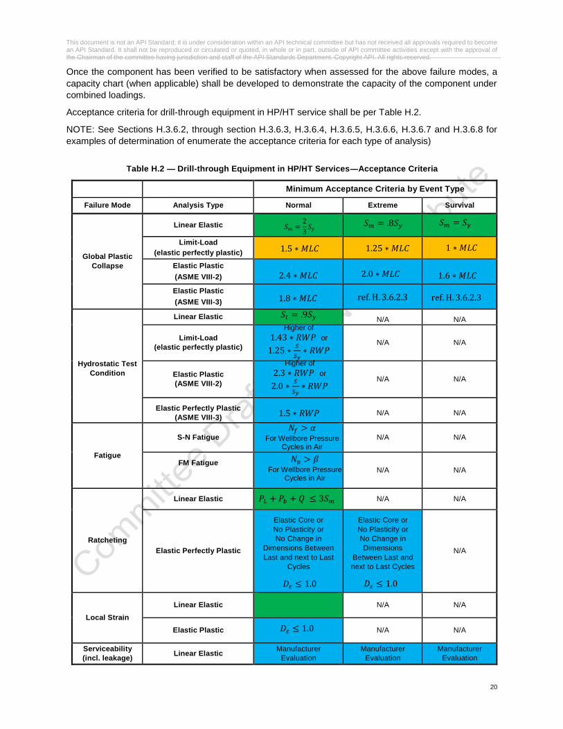
Once the component has been verified to be satisfactory when assessed for the above failure modes, a
capacity chart (when applicable) shall be developed to demonstrate the capacity of the component under
combined loadings.
Acceptance criteria for drill-through equipment in HP/HT service shall be per Table H.2.
NOTE: See Sections H.3.6.2, through section H.3.6.3, H.3.6.4, H.3.6.5, H.3.6.6, H.3.6.7 and H.3.6.8 for
examples of determination of enumerate the acceptance criteria for each type of analysis)
Table H.2 — Drill-through Equipment in HP/HT Services―Acceptance Criteria
Minimum Acceptance Criteria by Event Type
Failure Mode Analysis Type Normal Extreme Survival
Global Plastic
Collapse
Linear Elastic
Limit-Load
(elastic perfectly plastic)
Elastic Plastic
(ASME VIII-2)
Elastic Plastic
(ASME VIII-3)
Hydrostatic Test
Condition
Linear Elastic N/A N/A
Limit-Load
(elastic perfectly plastic)
N/A N/A
Elastic Plastic
(ASME VIII-2)
N/A N/A
Elastic Perfectly Plastic
(ASME VIII-3)
N/A N/A
Fatigue
S-N Fatigue
N/A N/A
FM Fatigue
N/A N/A
Ratcheting
Linear Elastic N/A N/A
Elastic Perfectly Plastic
Elastic Core or
No Plasticity or
No Change in
Dimensions Between
Last and next to Last
Cycles
Elastic Core or
No Plasticity or
No Change in
Dimensions
Between Last and
next to Last Cycles
N/A
Local Strain
Linear Elastic N/A N/A
Elastic Plastic N/A N/A
Serviceability
(incl. leakage) Linear Elastic
Manufacturer
Evaluation
Manufacturer
Evaluation
Manufacturer
Evaluation
𝑆𝑚 =2
3𝑆𝑦
𝑃𝐿 + 𝑃𝑏 + 𝑄 ≤ 3𝑆𝑚
𝐷𝜀 ≤ 1.0
𝑁𝑓 > 𝛼 For Wellbore Pressure
Cycles in Air
𝑁𝑝 > 𝛽 For Wellbore Pressure
Cycles in Air
𝑆𝑡 = .9𝑆𝑦
Higher of
1.43 ∗ 𝑅𝑊𝑃 or
1.25 ∗𝑆
𝑆𝑦∗ 𝑅𝑊𝑃
2.4 ∗ 𝑀𝐿𝐶 2.0 ∗ 𝑀𝐿𝐶 1.6 ∗ 𝑀𝐿𝐶
1.8 ∗ 𝑀𝐿𝐶
1.5 ∗ 𝑀𝐿𝐶
Higher of
2.3 ∗ 𝑅𝑊𝑃 or
2.0 ∗𝑆
𝑆𝑦∗ 𝑅𝑊𝑃
1.5 ∗ 𝑅𝑊𝑃
𝑆𝑚 = .8𝑆𝑦 𝑆𝑚 = 𝑆𝑦
1.25 ∗ 𝑀𝐿𝐶 1 ∗ 𝑀𝐿𝐶
𝐷𝜀 ≤ 1.0
ref. H. 3.6.2.3 ref. H. 3.6.2.3
𝐷𝜀 ≤ 1.0

This document is not an API Standard; it is under consideration within an API technical committee but has not received all approvals required to become an API Standard. It shall not be reproduced or circulated or quoted, in whole or in part, outside of API committee activities except with the approval of the Chairman of the committee having jurisdiction and staff of the API Standards Department. Copyright API. All rights reserved.
21
Elastic Plastic Manufacturer
Evaluation
Manufacturer
Evaluation
Manufacturer
Evaluation
Global Plastic Collapse
Linear-Elastic Analysis
For elastic analysis, stress components shall be calculated, combined, and compared to limits for each
category of stress based on multiples of the design stress, 𝑆𝑚, for the material in use and for the category
of stress. This analysis methodology is described in API 6X and ASME VIII-2. The use of von Mises
equivalent stress is permitted.
For the normal condition, the basic stress limit, 𝑆𝑚 , shall be two thirds of the minimum specified yield
strength, 𝑆𝑦 (refer to Equation H.1)
𝑺𝒎 =𝟐
𝟑𝑺𝒚 (H.1)
For the extreme and survival conditions, the stress limits shall be as specified in Table H.2.
The three basic stress categories and associated limits shall be satisfied for plastic collapse as defined
below. The terms general primary membrane stress, local primary membrane stress, primary bending
stress, secondary stress, and peak stress used for elastic analysis are defined in the following paragraphs.
Stress categories and the allowable limits shall be per Table H.3.
• Check applicability of H3.5.2.1
• Acceptable for P<15,000 psi
• Acceptable for all pressure ratings
𝑆1 + 𝑆2 + 𝑆3 ≤ 4𝑆𝑚

This document is not an API Standard; it is under consideration within an API technical committee but has not received all approvals required to become an API Standard. It shall not be reproduced or circulated or quoted, in whole or in part, outside of API committee activities except with the approval of the Chairman of the committee having jurisdiction and staff of the API Standards Department. Copyright API. All rights reserved.
22
Table H.3 — Stress Categories and Limits
Stress Category
General Primary
Membrane
Local Primary Membrane
Primary Membrane plus
Bending
Secondary Membrane Plus
Bending Peak
Description
Average primary stress across solid
section. Excludes
discontinuities and
concentrations. Produced only by mechanical
loads.
Average stress across any solid
section. Considers
discontinuities but not
concentrations. Produced only by
mechanical loads.
Combination of average stress across a solid
and stress proportional to
the distance from the centroid.
Excludes discontinuities
and concentrations.
Produced only by mechanical
loads.
Stress necessary for self-constraint of the structure, where yielding can cause the magnitude of the stress to be
reduced. Excludes local stress
concentrations.
Total Stress, including stress due to a stress
concentration that does not cause notable
distortion. Sources can also be thermal
stresses.
Symbol 𝑃𝑚 𝑃𝐿 𝑃𝐿 + 𝑃𝑏 𝑃𝐿 + 𝑃𝑏 + 𝑄 𝑃𝐿 + 𝑃𝑏 + 𝑄 + 𝐹
Limit 𝑆𝑚 1.5𝑆𝑚 1.5𝑆𝑚 3𝑆𝑚 𝑆𝑎*
NOTE 𝑆𝑎 is obtained from fatigue curves. The allowable stress for the full range of fluctuation is 2𝑆𝑎 when performing an S-N
fatigue evaluation.
Reference: ASME VIII-2 (2015)
― General Primary Membrane Stress (𝑃𝑚)
The general primary membrane stress is the average value across the thickness of a section, produced
by primary loads including design internal or external pressure and other specified mechanical loads
but excluding all secondary and peak stresses.
― Local Primary Membrane Stress (𝑃𝐿)
The local primary membrane stress is average value across the thickness of a section, produced by
primary loads including design internal or external pressure and other specified mechanical loads but
excluding all secondary and peak stresses. A region of stress in a component is considered as local if
the distance over which the stress exceeds 1.1𝑆𝑚 does not extend in the meridional direction more
than √𝑅𝑡.
Regions of local primary membrane stress that exceed 1.1𝑆𝑚 shall be separated in the meridional
direction by a distance equal to or greater than 1.25√(𝑅1 + 𝑅2)(𝑡1 + 𝑡2) . Discrete regions of local
primary membrane stress, such as those resulting from concentrated loads on support brackets, where
the membrane stress exceeds 1.1𝑆𝑚, shall be spaced so that there is not an overlapping area in which
the membrane stress exceeds 1.1𝑆𝑚.
― Primary Membrane (General or Local) Plus Primary Bending Stress (𝑃𝐿 + 𝑃𝑏)
The Primary Membrane (General or Local) Plus Primary Bending Stress consists of the primary
membrane stresses as defined above plus the stresses due to resisting the bending moment at the
center of a flat plate or cover. [The bending stresses classed as 𝑃𝑏result from a free body diagram cut
through the flat plate or cover and are the result of couples needed for static equilibrium. All other
“bending” stresses are considered secondary “Q.”]

This document is not an API Standard; it is under consideration within an API technical committee but has not received all approvals required to become an API Standard. It shall not be reproduced or circulated or quoted, in whole or in part, outside of API committee activities except with the approval of the Chairman of the committee having jurisdiction and staff of the API Standards Department. Copyright API. All rights reserved.
23
Limit-Load Analysis
For a limit-load analysis, loading shall be incrementally increased up to the load which causes overall
structural instability or the factored load according to LRFD (ref to Table H.2). Actual normal load capacity
shall not exceed two thirds of the limit analysis collapse loading, based on the last converged valid load
case. Extreme and survival conditions have adjusted load factors according to Table H.1.
Elastic-Plastic Analysis
All load combinations shall have the same load factor, so that the assurance against failure will be the same
regardless of load combination. If ASME VIII-2 is followed, the load factor shall be 2.4 for the normal
condition. If ASME VIII-3 is followed, the load factor shall be 1.8 for the normal condition.
For the extreme and survival conditions, the load factors for ASME VIII -2 using elastic-plastic analysis
shall be 2.0 and 1.6, respectively. For the extreme and survival conditions, the load factors for ASME
VIII-3 using elastic-plastic analysis are still to be determined. Load factors proposed by manufacturer for
extreme and survival conditions with ASME VIII-3 shall require justification by verification and validation.
NOTE 1: A plastic collapse load is the load that causes overall structural instability. This point is indicated
by the inability to achieve an equilibrium solution for a small increase in load (e.g. the solution will not
converge). A global plastic collapse load is calculated established by performing an elastic–plastic analysis
of the component subject to the specified loading conditions.
NOTE 2: The concept of load resistance factor design (LRFD) is used as an alternative to the rigorous
computation of a plastic collapse load to assess a component. In this procedure, factored loads that include
a load factor to account for uncertainty and the resistance of the component to these factored loads are
analyzed using elastic–plastic analysis. If convergence is achieved at the load factor shown in Table H.2,
the component is stable under the applied loads for this load case
Local Strain Limit
Linear-Elastic Analysis
The triaxial stress limit (Equation H.2) shall be used for checking the linear-elastic local criterion.
𝑺𝟏 + 𝑺𝟐 + 𝑺𝟑 ≤ 𝟒𝑺𝒎 (H.2)
Elastic-Plastic Analysis
The elastic-plastic local strain criteria shall be satisfied for elastic-plastic analysis according to ASME VIII-
2, Paragraph 5.3.3, or ASME VIII-3, Article KD-232. The local strain criteria shall be evaluated at conditions
above the normal condition for the elastic-plastic analysis (e.g. 1.7 for ASME VIII-2, 1.28 for ASME VIII-3).
The local strain criteria are also evaluated for a load histogram. The location in the component is acceptable
for the specified loading sequence if the accumulated strain limit damage is less than the allowable.
𝐃𝛆 ≤ 𝟏. 𝟎 (H.3)
Serviceability
The component shall be evaluated according to the serviceability criteria set forth by the manufacturer.
Criteria for evaluation shall focus on well integrity and clearance to allow functionality of the equipment.
Examples of some of the considerations in this evaluation are the effect of deformation and deflection on:
1) gasket mating faces (contact pressure)
2) seal locations (extrusion gaps)
This document is not an API Standard; it is under consideration within an API technical committee but has not received all approvals required to become an API Standard. It shall not be reproduced or circulated or quoted, in whole or in part, outside of API committee activities except with the approval of the Chairman of the committee having jurisdiction and staff of the API Standards Department. Copyright API. All rights reserved.
24
3) misalignment of locking segments
Ratcheting
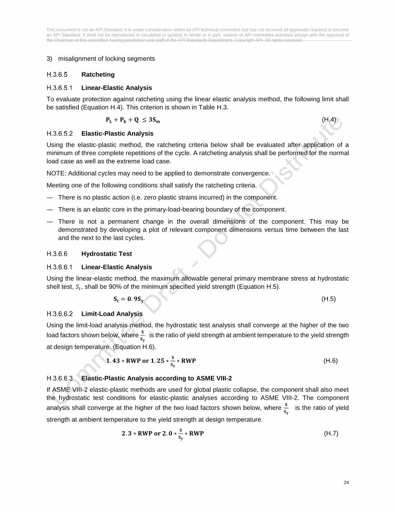
Linear-Elastic Analysis
To evaluate protection against ratcheting using the linear elastic analysis method, the following limit shall
be satisfied (Equation H.4). This criterion is shown in Table H.3.
𝐏𝐋 + 𝐏𝐛 + 𝐐 ≤ 𝟑𝐒𝐦 (H.4)
Elastic-Plastic Analysis
Using the elastic-plastic method, the ratcheting criteria below shall be evaluated after application of a
minimum of three complete repetitions of the cycle. A ratcheting analysis shall be performed for the normal
load case as well as the extreme load case.
NOTE: Additional cycles may need to be applied to demonstrate convergence.
Meeting one of the following conditions shall satisfy the ratcheting criteria.
― There is no plastic action (i.e. zero plastic strains incurred) in the component.
― There is an elastic core in the primary-load-bearing boundary of the component.
― There is not a permanent change in the overall dimensions of the component. This may be
demonstrated by developing a plot of relevant component dimensions versus time between the last
and the next to the last cycles.
Hydrostatic Test
Linear-Elastic Analysis
Using the linear-elastic method, the maximum allowable general primary membrane stress at hydrostatic
shell test, 𝑆𝑡, shall be 90% of the minimum specified yield strength (Equation H.5).
𝐒𝐭 = 𝟎. 𝟗𝐒𝐲 (H.5)
Limit-Load Analysis
Using the limit-load analysis method, the hydrostatic test analysis shall converge at the higher of the two
load factors shown below, where 𝐒
𝐒𝐲 is the ratio of yield strength at ambient temperature to the yield strength
at design temperature. (Equation H.6).
𝟏. 𝟒𝟑 ∗ 𝐑𝐖𝐏 𝐨𝐫 𝟏. 𝟐𝟓 ∗𝐒
𝐒𝐲∗ 𝐑𝐖𝐏 (H.6)
Elastic-Plastic Analysis according to ASME VIII-2
If ASME VIII-2 elastic-plastic methods are used for global plastic collapse, the component shall also meet
the hydrostatic test conditions for elastic-plastic analyses according to ASME VIII-2. The component
analysis shall converge at the higher of the two load factors shown below, where 𝐒
𝐒𝐲 is the ratio of yield
strength at ambient temperature to the yield strength at design temperature.
𝟐. 𝟑 ∗ 𝐑𝐖𝐏 𝐨𝐫 𝟐. 𝟎 ∗𝐒
𝐒𝐲∗ 𝐑𝐖𝐏 (H.7)

This document is not an API Standard; it is under consideration within an API technical committee but has not received all approvals required to become an API Standard. It shall not be reproduced or circulated or quoted, in whole or in part, outside of API committee activities except with the approval of the Chairman of the committee having jurisdiction and staff of the API Standards Department. Copyright API. All rights reserved.
25
Elastic-Plastic Analysis according to ASME VIII-3
If ASME VIII-3 elastic-plastic methods are used for global plastic collapse, the component shall also meet
the hydrostatic test conditions according to KD-236. An elastic-perfectly plastic material model shall be
used, and the component analysis shall converge at the load factor below.
𝟏. 𝟓 ∗ 𝐑𝐖𝐏 (H.8)
Fatigue
Alternating Stress (or Strain) Analysis (S-N Analysis)
For API 16A drill-though equipment in HP/HT services, evaluated with S-N analysis, the minimum
acceptance criterion for wellbore pressure loading shall be the estimated number of design cycles over the
service life of the component when using material properties in air. Additional environments and load
conditions shall be evaluated, with the results documented by the manufacturer.
𝐍𝐟 > 𝛂 (H.9)
𝜶 = 𝑬𝒙𝒑𝒆𝒄𝒕𝒆𝒅 𝒘𝒆𝒍𝒍𝒃𝒐𝒓𝒆 𝒑𝒓𝒆𝒔𝒔𝒖𝒓𝒆 𝒄𝒚𝒄𝒍𝒆𝒔 𝒐𝒗𝒆𝒓 𝒕𝒉𝒆 𝒔𝒆𝒓𝒗𝒊𝒄𝒆 𝒍𝒊𝒇𝒆 𝒐𝒇 𝒕𝒉𝒆 𝒄𝒐𝒎𝒑𝒐𝒏𝒆𝒏𝒕
NOTE: The result of the S-N analysis is a calculated number of design cycles, 𝑵𝒇, for each type of operating
cycle, and a cumulative number of design cycles when more than one type of operating cycle exists.
Fracture Mechanics (FM) Analysis
For API 16A drill-though equipment in HP/HT services, the minimum acceptance criterion shall be for a
loading histogram of wellbore pressure only, with material properties in air.
The minimum acceptance criteria for the number of allowable cycles from a FM analysis of components
due to wellbore only loading with air material properties shall be the estimated number of allowable cycles
over the maintenance interval of the component. Additional environments and load conditions shall be
evaluated, with the results documented by the manufacturer.
𝐍𝐩 > 𝜷 (H.10)
𝜷 = 𝑬𝒙𝒑𝒆𝒄𝒕𝒆𝒅 𝒘𝒆𝒍𝒍𝒃𝒐𝒓𝒆 𝒑𝒓𝒆𝒔𝒔𝒖𝒓𝒆 𝒄𝒚𝒄𝒍𝒆𝒔 𝒐𝒗𝒆𝒓 𝒕𝒉𝒆 𝒎𝒂𝒊𝒏𝒕𝒆𝒏𝒂𝒏𝒄𝒆 𝒊𝒏𝒕𝒆𝒓𝒗𝒂𝒍 𝒐𝒇 𝒕𝒉𝒆 𝒄𝒐𝒎𝒑𝒐𝒏𝒆𝒏𝒕
A separate assessment shall be performed for the extreme event and survival event. Each event shall be
evaluated separately using the maximum allowable crack size as the crack size to ensure brittle failure
does not occur due to one application of extreme or survival loading.
NOTE: The result of the FM analysis is a calculated number of allowable cycles, 𝑵𝒑, for a specified loading
histogram. Loading histograms will vary due to different locations, end-users/operators, operating
conditions, and other factors
Closure Bolting Acceptance Criteria
Bolts shall be evaluated based on the minimum cross sectional area of the bolt or stud root area (or reduced
shank area). Closure bolting stresses shall be determined considering:
― Initial bolt-up (preload)
― Operating conditions including pressure loads, external mechanical loads, and thermal stresses.
― Hydrostatic test pressure conditions

This document is not an API Standard; it is under consideration within an API technical committee but has not received all approvals required to become an API Standard. It shall not be reproduced or circulated or quoted, in whole or in part, outside of API committee activities except with the approval of the Chairman of the committee having jurisdiction and staff of the API Standards Department. Copyright API. All rights reserved.
26
Bolting normal stress limits for linear-elastic, elastic-perfectly-plastic and elastic-plastic analyses using
linear elastic bolting shall use the criteria defined in API 16A Section 4.4.3. Bolting allowable membrane
stresses for extreme and survival loadings are as follows:
𝑬𝒙𝒕𝒓𝒆𝒎𝒆 = 𝟎. 𝟗𝑺𝒚
𝑺𝒖𝒓𝒗𝒊𝒗𝒂𝒍 = 𝟏. 𝟎𝑺𝒚
Bolting allowable membrane plus bending stresses for extreme and survival loadings are as follows, relative
to the minimum bolt ultimate stress value (UTS):
𝑬𝒙𝒕𝒓𝒆𝒎𝒆 = 𝟏. 𝟎 𝑼𝑻𝑺
𝑺𝒖𝒓𝒗𝒊𝒗𝒂𝒍 = 𝟏. 𝟎 𝑼𝑻𝑺
Acceptance criteria for closure bolting using elastic-perfectly-plastic (limit-load) and elastic-plastic methods
(ASME VIII-2 / ASME VIII-3) shall be applied in the same manner as the pressure containing components
of the assembly.
Bolting Fatigue
Pressure retaining bolting shall be evaluated for fatigue. FM or S-N analysis may be used to evaluate bolt
fatigue.
Capacity Chart
In order for equipment to be given a normal capacity it shall meet the acceptance criteria of the following
failure modes (when applicable). If the component meets one criterion but not another, the normal capacity
shall be reduced until all criteria are met. Figure H.3 provides an example of obtaining an operating capacity
from plastic collapse loading.
― Global Plastic Collapse
― Local Strain Limit
― Serviceability
― Ratcheting
In order for equipment to be given an extreme capacity it shall meet the following acceptance criteria. If the
component meets one criterion but not another, the extreme capacity shall be reduced until all criteria are
met.
― Global Plastic Collapse (elastic-plastic with load factor according to Table H.2)
― Serviceability
― Ratcheting
In order for equipment to be given a survival capacity it shall meet the following acceptance criteria. If the
component meets one criteria but not another, the survival capacity shall be reduced until both criteria are
met.
― Global Plastic Collapse (elastic-plastic with load factor according to Table H.2)
― Serviceability (pressure integrity only)

This document is not an API Standard; it is under consideration within an API technical committee but has not received all approvals required to become an API Standard. It shall not be reproduced or circulated or quoted, in whole or in part, outside of API committee activities except with the approval of the Chairman of the committee having jurisdiction and staff of the API Standards Department. Copyright API. All rights reserved.
27
Figure H.3 ― Example of Obtaining an Operating Capacity from Collapse Loading
NOTE 1: It is important to understand the purpose of the capacity lines so that the severity of loadings can be understood. Each capacity line represents the maximum value of loading that is acceptable for that condition. The normal capacity line represents the maximum loading for normal conditions; in the same way the extreme and survival lines represent the maximum loading for their respective conditions.
NOTE 2: For clarity, this concept is demonstrated in Figure H.4, where:
― The green region (inside the normal capacity line) represents rated load cases.
― The yellow region (between the normal and extreme capacity lines) represents extreme load cases.
― The red region (between the extreme and survival capacity lines) represents survival load cases.
Figure H.4― Operating Capacity Regions
0
5
10
15
20
25
30
35
40
0 5 10 15 20 25 30 35 40
We
llbo
re P
ress
ure
(ks
i)
Bending Moment (M ft-lbs)
Operating Capacity from Collapse Loading
Operating Capacity (0 Tension)
Collapse Loading (0 Tension)

This document is not an API Standard; it is under consideration within an API technical committee but has not received all approvals required to become an API Standard. It shall not be reproduced or circulated or quoted, in whole or in part, outside of API committee activities except with the approval of the Chairman of the committee having jurisdiction and staff of the API Standards Department. Copyright API. All rights reserved.
28
H.4 Material for Drill-Through Equipment
H.4.1 General
This section shall apply to metallic and non-metallic materials for construction of pressure containing and
pressure controlling components used in API 16A drill-through equipment for HP/HT application.
In addition to meeting the material requirements, materials used for HP/HT applications shall meet the
requirements related to environmental fracture toughness, S-N fatigue, and fatigue crack growth rate found
in this Annex when applicable per the design verification requirements. This can be done by testing, or by
reference to relevant and documented field experience or existing test results.
Material testing requirements for non-metallic materials used in HP/HT environments shall determine
adequate resistance to swelling, weight gain, explosive decompression, loss of elasticity, etc.
NOTE: As in similar degradation mechanisms for standard applications, these requirements arise because
of the generally adverse effects of temperature, pressure, drilling fluids, completion fluids and produced
fluids on these materials and their properties.
H.4.2 Certification Documentation
The manufacturer shall maintain necessary documentation to show:
― Conformance with the material specification, manufacturing process and this annex;
― Applicable testing and NDE inspection are performed and meet the requirement;
― Any welding, when permitted, is performed in accordance with qualified procedures and recorded in a
weld map.
H.4.3 Materials Selection Requirements
The equipment manufacturer shall perform materials selection as part of normal design activities. The end-
user/operator should review and accept the manufacturer’s material selections for all components.
Castings shall not be used for pressure containing components.
Materials selected for drill-through equipment for used on HP/HT developments/wells shall conform to
ANSI/NACE MR0175/ISO 15156 requirements.
The process of materials selection shall reflect the outcomes of additional joint activities between end-
user/operator, manufacturer and material manufacturer, such as:
― Categorization of equipment
― Selection of design and design verification methodologies
― Assessment of loading conditions
― Assessment of likely service environments and environmental severity (refer to ANSI/NACE
MR0175/ISO 15156 for more information or ISO 23936 or NACE TM0187 as applicable)
― Assessment of relevant industry experience
The end-user/operator should provide the manufacturer with a functional specification containing the
information related to internal (pressure) loading, external loading, operations, and expected service
conditions (including upset conditions) necessary in order for the manufacturer to develop the
materials/environmental exposure matrix. The manufacturer is to carry out the tasks related to evaluation
of loading conditions and assessment of environments and environmental severity; leading to selection of
design methodology, assessment of risk, and ultimately to materials selection.

This document is not an API Standard; it is under consideration within an API technical committee but has not received all approvals required to become an API Standard. It shall not be reproduced or circulated or quoted, in whole or in part, outside of API committee activities except with the approval of the Chairman of the committee having jurisdiction and staff of the API Standards Department. Copyright API. All rights reserved.
29
The manufacturer, as part of the design verification process, shall prepare materials/environmental
exposure matrices showing each drill-through component alongside the material from which each
component will be made and the environments to which each is expected to be exposed. The materials
matrices shall be reviewed by and determined to be acceptable by the end-user/operator.
H.4.4 Material Specification
General
Material specifications (MS) and or supporting documents shall contain the following information as a
minimum:
― Scope of the specification or application;
― Referenced standards and Specification Level, as applicable;
― Material manufacturing requirements, e.g., steelmaking, hot/cold working, heat treatment, etc.;
― Chemical composition requirements, with tolerances;
― Requirements for mechanical, physical and microstructural evaluation and their acceptance criteria.
― Requirements for non-destructive examination (NDE) and acceptance criteria;
― Traceability requirements;
― Handling and marking requirements; and
― Supplemental requirements
Manufacturing Procedure Specification
The manufacturer shall prepare a manufacturing procedure specification (MPS) to include, as a minimum,
the material specification, general process control variables and the heat treat parameters, in accordance
with the following:
― For castings, refer to API 20A 5.2 & 5.3;
― For open die shaped forgings, refer to API 20B 5.3 & 5.4;
― For closed die forgings, refer to API 20C 5.3 & 5.4;
― For alloy and carbon steel fasteners, refer to API 20E 5.3;
― For CRA fasteners, refer to API 20F 5.3;
― For piping, refer to API 5L Section 8 & Annex H;
― For any other product form or grade not covered above, information to be included in the MPS should
be agreed between the manufacturer and end-user/operator.
Alternative industry specifications covering MPS requirements may be used by agreement between the
equipment user and vendor provided they meet the requirements listed in the specification referenced
above.
Nonmetallic Material Specifications
Each manufacturer shall have written specifications for nonmetallic materials used in the production of HPHT drill-through equipment.
Elastomeric materials shall be controlled by material specifications meeting the requirements of API 16A
as defined for nonmetallic parts (Section H.5.2.2). In addition, the material specification shall define the
material type per ASTM D1418.
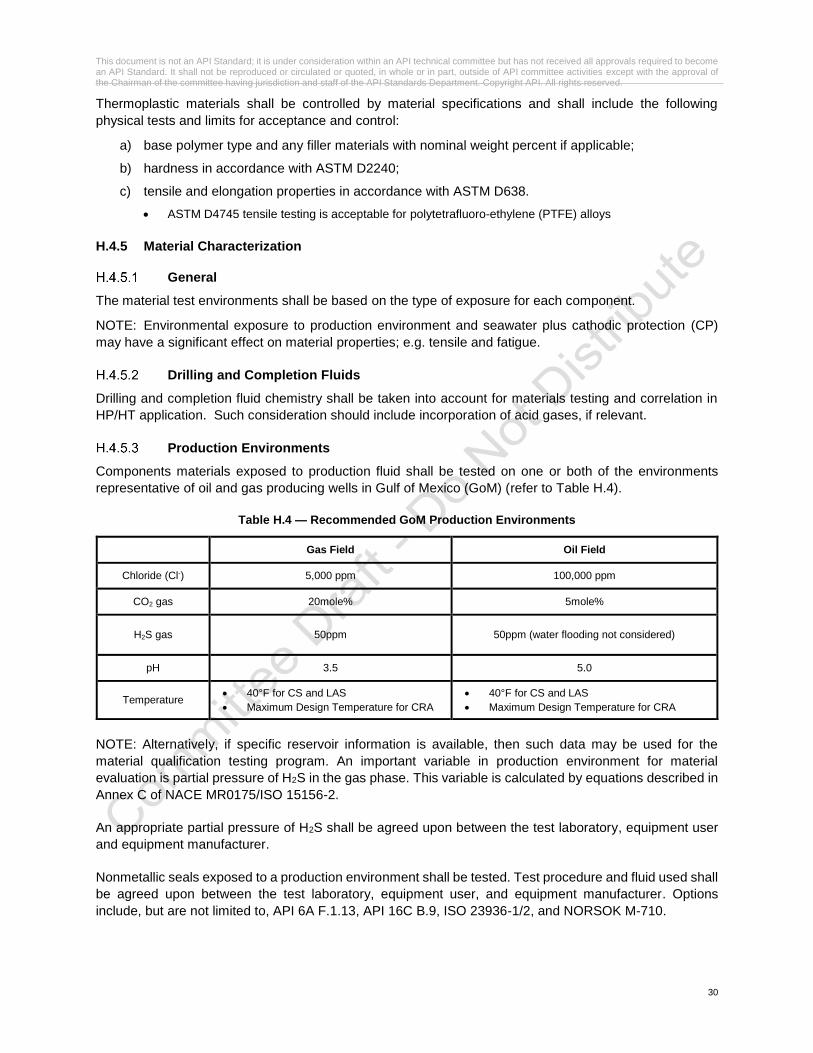
This document is not an API Standard; it is under consideration within an API technical committee but has not received all approvals required to become an API Standard. It shall not be reproduced or circulated or quoted, in whole or in part, outside of API committee activities except with the approval of the Chairman of the committee having jurisdiction and staff of the API Standards Department. Copyright API. All rights reserved.
30
Thermoplastic materials shall be controlled by material specifications and shall include the following
physical tests and limits for acceptance and control:
a) base polymer type and any filler materials with nominal weight percent if applicable;
b) hardness in accordance with ASTM D2240;
c) tensile and elongation properties in accordance with ASTM D638.
• ASTM D4745 tensile testing is acceptable for polytetrafluoro-ethylene (PTFE) alloys
H.4.5 Material Characterization
General
The material test environments shall be based on the type of exposure for each component.
NOTE: Environmental exposure to production environment and seawater plus cathodic protection (CP)
may have a significant effect on material properties; e.g. tensile and fatigue.
Drilling and Completion Fluids
Drilling and completion fluid chemistry shall be taken into account for materials testing and correlation in
HP/HT application. Such consideration should include incorporation of acid gases, if relevant.
Production Environments
Components materials exposed to production fluid shall be tested on one or both of the environments
representative of oil and gas producing wells in Gulf of Mexico (GoM) (refer to Table H.4).
Table H.4 — Recommended GoM Production Environments
Gas Field Oil Field
Chloride (Cl-) 5,000 ppm 100,000 ppm
CO2 gas 20mole% 5mole%
H2S gas 50ppm 50ppm (water flooding not considered)
pH 3.5 5.0
Temperature • 40°F for CS and LAS
• Maximum Design Temperature for CRA
• 40°F for CS and LAS
• Maximum Design Temperature for CRA
NOTE: Alternatively, if specific reservoir information is available, then such data may be used for the
material qualification testing program. An important variable in production environment for material
evaluation is partial pressure of H2S in the gas phase. This variable is calculated by equations described in
Annex C of NACE MR0175/ISO 15156-2.
An appropriate partial pressure of H2S shall be agreed upon between the test laboratory, equipment user
and equipment manufacturer.
Nonmetallic seals exposed to a production environment shall be tested. Test procedure and fluid used shall
be agreed upon between the test laboratory, equipment user, and equipment manufacturer. Options
include, but are not limited to, API 6A F.1.13, API 16C B.9, ISO 23936-1/2, and NORSOK M-710.

This document is not an API Standard; it is under consideration within an API technical committee but has not received all approvals required to become an API Standard. It shall not be reproduced or circulated or quoted, in whole or in part, outside of API committee activities except with the approval of the Chairman of the committee having jurisdiction and staff of the API Standards Department. Copyright API. All rights reserved.
31
Seawater with/without Cathodic Protection
Components materials exposed to seawater shall be tested in simulated seawater with CP if applicable.
The CP shall be applied by the impressed current method, and the cathodic protection potential shall be
measured with respect to a standard silver/silver chloride (Ag/AgCl) reference electrode. The standard
simulated seawater test with CP shall have the following environmental conditions identified in Table H.5.
The simulated seawater in Table H.4 shall be deaerated to maximize surface hydrogen coverage and as a
result, hydrogen uptake.
Table H.5 — Recommended Seawater Test Environment
Seawater Test Environments
NaCl 3.5wt% dissolved in water Ambient (40°F)
pH 8.2 (adjusted with NaOH) Ambient (40°F)
Electrode Potential -1000 to -1100 mV vs.Ag/AgCl Ambient (40°F)
Environmental Screening and Reduction Factors by Slow Strain Rate Test (SSRT)
General
The material susceptibility to environmental cracking shall be defined using an SSRT evaluation. The SSRT
evaluation shall meet the guidelines of NACE MR0175/ISO 15156 and TM0198. The visual examination
acceptance shall meet a Class 2 as a minimum. The ductility parameters as defined in TM0198 shall report:
― Percent (%) elongation
― Percent (%) reduction in area
― Total time to failure
The acceptance of ductility parameters against the baseline material tests shall be defined for a given alloy
at a given temperature. SSRT evaluation shall include at least 2 heats. Tests per heat shall include at least
2 specimens in air, and at least 3 specimens per test environment. The Class 2 criteria in accordance with
NACE TM0198 require a maximum change in ductility to be less than 20%. Ductility loss greater than the
Class 1 shall be further evaluated with metallography of the test specimen’s gage and observation at 100X
or scanning electron microscopy to more fully characterize the failed specimen with respect to stress
corrosion cracking (SCC) behavior. There shall be no observed secondary cracking identified in the
evaluation.
The results of the SSRT evaluation shall be used to define the environmental susceptibility of materials for
fatigue and fracture toughness testing.
― Materials that meet the criteria of the SSRT evaluation (or material not susceptible to environmental
assisted cracking in environment) shall be designated as not susceptible to the environmental cracking
(fatigue and sustained). Consequently, fatigue testing of S-N, fatigue crack growth da/dN vs ΔK and
fracture toughness, KIC, are defined in H.4.5.5.2. Correlation of fatigue properties between air and
environmental conditions shall be evaluated for validation of SSRT evaluation.
― Materials that do not meet the criteria of the SSRT evaluation (or material susceptible to environmental
assisted cracking in environment) shall be designated as susceptible to environmental cracking (fatigue
and sustained). Consequently, fatigue testing of S-N, fatigue crack growth da/dN vs ΔK and fracture
toughness KIC shall be performed as defined in H.4.5.4.3.

This document is not an API Standard; it is under consideration within an API technical committee but has not received all approvals required to become an API Standard. It shall not be reproduced or circulated or quoted, in whole or in part, outside of API committee activities except with the approval of the Chairman of the committee having jurisdiction and staff of the API Standards Department. Copyright API. All rights reserved.
32
The results of the SSRT evaluation shall be used as design reduction factor for strain limit damage if
required. Reduction in % elongation or % reduction in area shall be used as reduction factor for strain limit
damage material parameters.
Material Not Susceptible to Environmental Assisted Cracking in Environment
H.4.5.5.2.1 General
Fatigue properties for materials that are not susceptible to environmental assisted cracking (EAC) shall be
developed as described in the following sections.
H.4.5.5.2.2 S-N Fatigue Curve
Development of S-N fatigue curve in air shall be conducted following the test procedures as defined in
H.4.6.4.2 and at a frequency of ≤ 10Hz. Higher or lower frequencies may be used based on design criteria.
H.4.5.5.2.3 Fracture Toughness, KIC
For materials determined not to be susceptible to EAC in defined environment (s) based on SSRT, the fracture toughness of the material tested in air at minimum or maximum design temperature shall be conducted using ASTM E1820 or E399. Additionally, this shall include the design temperature of the application that will provide conservative values. Alternatively, the CTOD toughness values may be obtained by using BS7448-01 or BS7448-04. ASTM E1820 tests shall define a J-Δa curve for the material tested. The fracture toughness values obtained from these tests are: KIC, KJIC, JIC or δC .
Thick wall pressure vessels typically reach a critical crack depth and length with very limited plastic deformation at the crack tip and fail in plane strain condition. It may not be practical to evaluate fracture toughness in plain strain condition as defined in ASTM E399, but an evaluation of thickness effects shall be performed for the fracture toughness testing as applicable.
Fracture toughness shall be conducted following the test procedures as defined in H.4.6.4.3.
H.4.5.5.2.4 Fatigue Crack Growth Rate, da/dN
Cyclic fatigue crack growth tests shall be conducted in air at maximum or minimum design temperature
when susceptibility to environment is not present. These tests shall follow the guidelines of ASTM E647.
The Kmax and initial R ratio shall be defined for the test. Fatigue crack growth rate shall be conducted
following the test procedures as defined in H.4.6.4.4.
NOTE 1: There are multiple methods of defining and correcting for closure at low ΔK values. The proposed
method in ASTM E647, Appendix A1 is the preferred method. The Kmax value is held constant with the Kmin
increasing and ΔK decreasing. This method has an increasing R ratio.
NOTE 2: Alternatively, the procedure for testing with the mean stress held constant may be used. This test
method allows the Kmax and Kmin to be decreasing along with the decrease in ΔK. This method has a
constant R ratio as ΔK decreases.
Material Susceptible to Environmental Assisted Cracking in Environment
H.4.5.5.3.1 General
Fatigue properties for materials that are susceptible to environmental assisted cracking (EAC) shall be
developed as described in the following sections.
H.4.5.5.3.2 S-N Fatigue Curve in Air plus Environmental Testing
S-N fatigue curve in air shall be developed per the test procedures defined in H.4.6.4.2 below at a frequency
≤ 10Hz, with reduced/minimum confirmation in environment with lower frequency at ≤ 0.3Hz.
For alloys other than carbon steel, the frequency shall appropriately reflect the frequency sensitivity to
environmental fatigue.

This document is not an API Standard; it is under consideration within an API technical committee but has not received all approvals required to become an API Standard. It shall not be reproduced or circulated or quoted, in whole or in part, outside of API committee activities except with the approval of the Chairman of the committee having jurisdiction and staff of the API Standards Department. Copyright API. All rights reserved.
33
NOTE: An example of S-N fatigue curve developed in air with correlation to environmental condition is
represented in Figure H.5:
Figure H.5―S-N Fatigue Curve Developed in Air with Correlation with Environment
NOTE: The reduced environmental tests may be generated and compared to published S-N air data for a
given alloy to confirm the results fall within the envelope of the air data curves.
H.4.5.5.3.3 Fracture Toughness, KIEAC
For materials determined to be susceptible to cracking when exposed to test environment (s) based on
SSRT, shall be tested for fracture toughness of the material in the defined operating environments of this
document as a standard. It is acceptable to test in less severe environments when actual production fluid
is provided as the design basis.
Environmental fracture toughness tests to obtain KIEAC, shall be conducted using rising displacement test
procedure of ASTM E1820. Alternatively, standard environmental static load threshold fracture toughness
test of ASTM E1681 may be used to define the KIEAC values.
Tests conducted for KIEAC in H2S fluid containing and seawater with CP environments shall define a
hydrogen saturation test solution exposure period for the test coupons prior to the start of the load cycle.
Fracture toughness testing shall be conducted following the test procedures as defined in H.4.6.4.3.
Fatigue Crack Growth, da/dN
Materials determined to be susceptible to the defined environment(s) based on SSRT shall be tested for
fatigue crack growth, da/dN vs ΔK, in the defined standard test environments of this document for oil and
gas environment. The test temperature shall be defined for the worst case condition depending on the
material and the environment combination using room temperature, seabed ambient temperature, minimum
design temperature or maximum design temperature conditions.
The frequency scanning procedures may be necessary to determine the range of frequencies to be used
for the cyclic fatigue crack growth rate testing. Frequency scanning tests should be performed at a constant
ΔK and R ratio, spanning the range of frequencies for which the component could be subjected to in service.
For the most critical frequency the fatigue crack growth rate should be quantified for the full range of ΔK.
Fatigue crack growth rate testing shall be conducted following the test procedures as defined in H.4.6.4.4.
Essential Variables for Material Characterization
The following attributes are essential variables that affect material properties and characterization:

This document is not an API Standard; it is under consideration within an API technical committee but has not received all approvals required to become an API Standard. It shall not be reproduced or circulated or quoted, in whole or in part, outside of API committee activities except with the approval of the Chairman of the committee having jurisdiction and staff of the API Standards Department. Copyright API. All rights reserved.
34
― Material Grade
― Change of the material designation, i.e., UNS number;
― Change of the specified limits of chemical compositions listed in the material specification;
― Increase of the specified minimum yield strength by 69 MPa (10,000 psi);
― Decrease of the specified Charpy V-notch (CVN) impact toughness or fracture toughness
requirements.
― Hot Forming (Forging, Extrusion, Rolling)
― Change in forming method (e.g. closed/open die, ring rolling, extrusion, hammer to press forging)
if applicable;
― Reduction of overall forging reduction ratio.
― Heat Treatment
― Change in post-forge thermal processes;
― Change in temperature and time of heat treatment outside the specified limit;
― Change in quench media if applicable.
― Thickness
― Increase in thickness over qualified thickness by 10%;
If any of the applicable essential variables listed in H.4.5.6 change, the material characterization testing
scope defined in Section H.4.5 shall be re-conducted unless technical justification is provided that such
change(s) will not impair the material’s performance or affect the functionality and service life of the
equipment.
H.4.6 Material Testing Protocol
Physical Properties
Physical properties required for design verifications shall be defined, as needed, and may include:
― Thermal expansion
― Thermal conductivity
― Specific heat capacity
― Density
NOTE Published data for physical properties may be available through the following references:
― Material test data, as provided by material manufacturers
― API TR6MET
― API 1PER15K-1
― MIL-HDBK-5J
― ASME BPVC II, Part D
Tensile Properties
Material testing for tensile properties (for metallic and non-metallic materials) shall be performed in
accordance with the industry standards referenced in Table H.6. Metallic material tensile properties shall
include:

This document is not an API Standard; it is under consideration within an API technical committee but has not received all approvals required to become an API Standard. It shall not be reproduced or circulated or quoted, in whole or in part, outside of API committee activities except with the approval of the Chairman of the committee having jurisdiction and staff of the API Standards Department. Copyright API. All rights reserved.
35
― Yield Strength (YS)
― Ultimate Tensile Strength (UTS)
― Reduction in Area
― Elongation
― Modulus of Elasticity
― Poisson’s Ratio
― True-Stress True-Strain: Evaluation of global plastic collapse is required for ASME VIII-2 Paragraph
5.2.4 and ASME VIII-3, Article KD-231. The global plastic collapse requires a defined input of material
true-stress true-strain properties at room temperature up to 50°F over the maximum design
temperature. There are two approaches to obtaining the properties, as follows:
a) ASME Methodology
1) Define minimum specified engineering yield and engineering ultimate strength at room
temperature and up to maximum design temperature in increments of 100°F for design
temperature above 250°F.
2) Convert to true stress-true strain using formulas of ASME VIII-3, Article KD-231.4 and the
material parameters in Table KD-230.5.
3) The minimum specified yield and ultimate strength for elevated temperatures should be defined
using the yield strength reduction ratios defined in API TR6 MET, up to and including 450°F.
4) Yield Strength and ultimate strength values at temperatures in increments of 100°F may be
obtained from ASME BPVC II, Part D Table Y-1 and Table U, respectively, as applicable.
5) The values used from these tables shall match the room temperature minimum yield and
ultimate strengths of the material being used for analysis.
b) Material Characterization/Testing
1) Conduct material tests for true-stress true-strain at room temperature and up to 50°F over the
maximum design temperature in increments of 100°F.
2) Each curve defined above room temperature shall be adjusted using the ratio of the minimum
yield strength divided by the actual yield strength at room temperature from tests.
3) Each point on the true-stress true-strain curve shall be adjusted by the defined ratio up to and
including the ultimate strength.
4) Above the ultimate strength the curve shall be considered perfectly-plastic. However, if the
true-stress true-strain is quantified beyond ultimate such data may be used.
Published data for tensile properties shall be acceptable if representative of the material processing and
size of the selected alloys and may be available through the following references:
― Material test data
― API TR6MET
― API 1PER15K-1
― MIL-HDBK-5J
― ASME BPVC II, Part D

This document is not an API Standard; it is under consideration within an API technical committee but has not received all approvals required to become an API Standard. It shall not be reproduced or circulated or quoted, in whole or in part, outside of API committee activities except with the approval of the Chairman of the committee having jurisdiction and staff of the API Standards Department. Copyright API. All rights reserved.
36
Fatigue Properties
General
Fatigue analyses require the material input parameters shall be either S-N fatigue curves or fracture
toughness (KIC) and cyclic fatigue crack growth (da/dN vs ΔK).
Properties for each shall be defined in the operating environments. Both S-N fatigue and cyclic fatigue crack
growth (da/dN vs ΔK) shall be obtained from material tests which are representative of the production parts.
The recommended test temperature shall be defined by the project design requirement. The number of
tests for both S-N and fracture mechanics shall be as follows:
― For S-N fatigue curves (strip specimens) in air, seawater plus cathodic protection and production fluids,
a minimum of (2) heats shall be evaluated with three (3) samples at low cycle range, three (3) samples
at mid-cycle range and three (3) samples at high cycle range. The acceptable design curve shall be
means minus two (2) standard deviations.
― For fatigue crack growth rate in air, seawater plus cathodic protection and produced fluids, samples
shall be taken from a minimum of two (2) heats with a minimum of three (3) samples from each heat.
S-N Fatigue Curve
S-N fatigue analysis procedures are defined in ASME VIII-2, Paragraph 5.5.3 and 5.5.4 and ASME VIII-3,
Article KD-3.
The material fatigue evaluation shall correspond to the failure modes of the component in environment as
well as the loading parameters of frequency, amplitude and mean stress.
Fatigue tests using smooth tensile cyclic loaded tests such as those defined in ASTM E466 and ASTM
E606 shall be acceptable for ambient conditions. Structural welds shall be evaluated using component test
coupons, were applicable.
NOTE: These through-thickness test coupons may be coated such that the environment is only exposed
to the well wetted surface, such as production or completion fluids environments.
Similarly, through thickness test coupons shall be coated where exposure to seawater surface is defined.
S-N curve shall be developed in air and environment, and the knock down factor determined to be used in
design.
The procedure for S-N curve development shall be as follows:
1) Number of Heats/Specimens: refer to H.4.6.4.1
2) Test Specimen Geometry: ASTM E466
3) Test Specimen Orientation: ASTM E466
4) Location: Location (s) of highest stress with 1/4T location either ID or OD based on loading conditions
for smooth tensile specimens.
5) Frequency:
― ≤ 10Hz in air
― ≤ 0.3Hz in environment
6) Load/Stress Ratio (R):
― Constant R Ratio (define range)/varying mean stress

This document is not an API Standard; it is under consideration within an API technical committee but has not received all approvals required to become an API Standard. It shall not be reproduced or circulated or quoted, in whole or in part, outside of API committee activities except with the approval of the Chairman of the committee having jurisdiction and staff of the API Standards Department. Copyright API. All rights reserved.
37
― Develop S-N curves based on high, med, and low fatigue life
― Constant Maximum Stress (σmax ≤ YS) and varying R ratio/varying mean stress
― Develop S-N curves based on high, med, and low fatigue life
― R ratio, mean stress and frequency defined by design requirements
― Fatigue Documentation: ASTM E468
Fracture Toughness, KIC
Fracture mechanics evaluation can be performed by using ASME VIII-3 Article KD-4. The evaluation for
crack growth to a critical crack length of through thickness requires the input parameters for cyclic fatigue
crack growth and fracture toughness.
These parameters shall be defined for the component operating environment.
The procedure for fracture toughness data development shall be as follows:
1) Number of Heats/Specimens: Two (2) heats and three (3) specimens according to heat
2) Test Specimen Geometry: ASTM E399 or ASTM E1681
3) Test Specimen Orientation: ASTM E399 or ASTM E1681 with consideration to direction of component
4) Locations: Location (s) of highest stress with 1/4T either ID or OD based on loading conditions
5) Test Specimen Pre-Cracking: ASTM E1820
6) K rate ≤ 0.0014ksi√in/s (≤ 0.05Nmm-3/2/s) in environment.
Fatigue Crack Growth, da/dN vs ΔK
Fracture mechanics evaluation can be performed by using ASME VIII-3 Article KD-4. The evaluation for
crack growth to a critical length of through thickness requires the input parameters of cyclic fatigue crack
growth and fracture toughness.
These parameters shall be defined for the component operating environment.
The procedure for fatigue crack growth data development is as follows:
1) Number of Heats/Specimens: refer to H.4.6.4.1
2) Test Specimen Geometry: ASTM E647
3) Test Specimen Orientation: ASTM E647
4) Location: Location (s) of highest stress with 1/4T either ID or OD, based on loading condition
5) Test Specimen Pre-Cracking: ASTM E647
6) Frequency:
― ≤ 10Hz in air
― ≤ 0.3Hz in environment (lower frequencies as determined by frequency scan tests)
7) Load/Stress Ratio (R):
― Constant R Ratio

This document is not an API Standard; it is under consideration within an API technical committee but has not received all approvals required to become an API Standard. It shall not be reproduced or circulated or quoted, in whole or in part, outside of API committee activities except with the approval of the Chairman of the committee having jurisdiction and staff of the API Standards Department. Copyright API. All rights reserved.
38
― Constant Kmax (refer to ASTM E647), to minimize crack closure effect near threshold
H.4.7 Local Strain Criteria – Material Data
General
Protection against local failure requires the input of material properties for triaxial strain. The triaxial strain
damage evaluation using ASME VIII-2 is made for factored load cases which include pressures and external
loads.
The strain damage evaluation using ASME VIII-3 shall require 1) an elastic plastic analysis using factored
pressure and external loads and 2) evaluation using elastic perfectly plastic analysis using non-factored
pressure (including hydrostatic testing), external loads and thermal loads. The material parameters for
triaxial strain damage shall be defined for room temperature up to maximum design temperature.
Local Strain: Susceptible to Environment
Strain damage material parameters should be defined for environment based on the results of the SSRT
tests. The minimum ratio of the air to environment values for elongation and reduction in area defined in
the SSRT test should be used as a reduction factor for all strain damage parameters defined for the
material.
In cases where SSRT is not an applicable methodology for characterization or too severe as a test,
alternative methodologies should be considered.
NOTE: An example would be use of a notched C-Ring with triaxiality and plasticity levels equivalent to the
component being evaluated.
Such alternate testing and evaluation methodologies should be considered where SSRT does not
accurately represent the material response or loadings in certain environments.
Local Strain: Material Parameters
The limiting triaxial strain material parameters may be defined by the following methods, as applicable for
API materials:
― Define material parameters at temperature using formulas defined in ASME VIII-2, Table 5.7 and
Paragraph 5.3.3.
― Define material parameters at temperature using formulas defined in ASME VIII-3, Table KD-230.5 and
Article KD-232.1.
― Conduct notched tensile tests defining material parameters for triaxiality factor and triaxial strain at
failure with results factored according to the ratio defined in the SSRT evaluation.
The uniaxial material strain limit parameters defined in ASME VIII-2, Table 5.7 and ASME VIII-3, Table KD-
230.5 require the notched and un-notched tensile test parameters:
R = Minimum specified yield/minimum specified ultimate strength
El = Minimum specified elongation, percent (%)
RA = Minimum specified reduction in area, percent (%)
α or m5 = Material parameters obtained from uniaxial notched tensile tests
These parameters shall be defined for the temperature ranges specified. Evaluation of local damage using
ASME VIII-3 where thermal stresses are part of the loading conditions shall require the data in Table KD
230.5 to be defined at the minimum and/or maximum operating conditions.
This document is not an API Standard; it is under consideration within an API technical committee but has not received all approvals required to become an API Standard. It shall not be reproduced or circulated or quoted, in whole or in part, outside of API committee activities except with the approval of the Chairman of the committee having jurisdiction and staff of the API Standards Department. Copyright API. All rights reserved.
39
The notched tensile tests should be conducted using standard test specimens and tested in accordance
with ASTM E8 and ASTM E21. The specimen sizes for tests shall be the following as a minimum;
D = Diameter outside of notch = 16mm
d = diameter of notch = 8mm
r = radius of notch = 50mm, 16mm, 8mm, 4mm, 1mm
H.4.8 Qualification of Raw Material Manufacturing Process or Providers
General
The manufacturing process (routes) or provider of raw materials to be used for pressure controlling and
pressure retaining component shall be qualified by testing of a representative material with the largest
critical cross section, generally referred as first article qualification. The test material shall represent the
size and geometry of the actual component and be fabricated following the manufacturing process intended
to be qualified.
Prior to the qualification process, the raw material provider shall submit the manufacturing process
specification (MPS) which contains the details as defined in H.4.4.2 for review by the manufacturer. Upon
approval, the first article shall be fabricated and subjected to testing in accordance with material
specification (MS) and MPS according to the MPS requirements.
Product Forms
General
Product forms may be defined as follows.
Forgings
Qualification of forgings shall follow testing requirements for forging specification level (FSL)-3 or FSL-4 as
defined in API 20B or API 20C whichever is applicable. Result of the testing shall meet the acceptance
criteria defined in the related sections of API 20B or API 20C for FSL-4 and in the Material Specifications
(MS). The test material shall represent the equipment critical section as determined by the equipment
manufacturer in the product design. The material shall be a prolongation, as defined in API 20B, or a
sacrificial production part. Simulated Post Weld Heat Treatment (SPWHT) may require extra material and
shall be addressed by the appropriate entity. Allowance for use of a separate QTC shall be agreed upon
by the manufacturer and the end user. Test sampling locations for qualification of forgings shall be
compliant with requirements of API 20B or API 20C whichever is applicable.
NOTE: API 20B does not provide acceptance criteria for mechanical properties. At best it provided
acceptance criteria for metallographic testing and forging requirements.
All testing and mechanical properties shall be agreed and accepted between the buyer and
manufacturer/supplier or as specified in the MPS.
Fasteners
Qualification of bolting shall follow testing requirements for bolting specification level (BSL) as specified per
API 16A Table 6 in accordance with API 20E for carbon and low alloy steel bolting and API 20F for CRA
bolting whichever is applicable. Results of the testing shall meet the acceptance criteria defined in the
related sections of API 20E and API 20F and the Material Specifications (MS).
NOTE: API 20E or API 20F do not provide acceptance criteria. The documents specify manufacturing
process and associated procedures with essential variables defined.
All material acceptance criteria with respect to mechanical properties is governed by fastener material
standard or specification and shall be agreed between the buyer and the manufacturer/ supplier

This document is not an API Standard; it is under consideration within an API technical committee but has not received all approvals required to become an API Standard. It shall not be reproduced or circulated or quoted, in whole or in part, outside of API committee activities except with the approval of the Chairman of the committee having jurisdiction and staff of the API Standards Department. Copyright API. All rights reserved.
40
Other Forms
Other forms of raw material may be elected to be used for pressure containing or pressure controlling
components. The qualification testing of such forms shall be defined by the manufacturer.
Fracture Mechanics Testing
Fracture toughness in air according to ASTM E1820 shall be included in the qualification process as
mandatory.
NOTE: Environmental fracture toughness and fatigue testing may not be required for the qualification of
each raw material manufacturing process or provider, if such testing has been performed during the
characterization process of MS according to H.4.5.
Simulated Post-weld Heat Treatment
If the component is subject to welding and PWHT, sufficient test coupon material shall be removed from
the sacrificial component and subject to a simulated post-weld heat treatment (SPWHT). The time and
temperature of the SPWHT cycle shall be the same as those specified in the actual WPS. It is advisable
to increase the SPWHT time to account for repairs during equipment manufacture. After the SPWHT,
tensile, CVN impact toughness, and hardness of the test coupon shall be tested, and the achieved values
shall meet the applicable MS.
H.4.9 Production QA/QC Testing
General
Testing shall be performed on production lots to ensure compliance with applicable design requirements.
NOTE: Table H.6 identifies the recognized industry standards for performing quality control material testing
for metallic materials.

This document is not an API Standard; it is under consideration within an API technical committee but has not received all approvals required to become an API Standard. It shall not be reproduced or circulated or quoted, in whole or in part, outside of API committee activities except with the approval of the Chairman of the committee having jurisdiction and staff of the API Standards Department. Copyright API. All rights reserved.
41
Table H.6 – Industry Standards Applicable to Metallic Quality Control Tests
Low-alloy Steels Duplex Stainless Steels Ni-Based Alloys
Chemical Composition ASTM A751 ASTM E350 ASTM E1806
ASTM E353 ASTM E1473
ASTM E55
Hardness ASTM A833, ASTM E10, ASTM E18, ASTM E140, ASTM E384
Yield Strength
ASTM A370, ASTM E8, ASTM E21
Tensile Strength
% Elongation
% Reduction in area
CVN Toughness
(20°F below LAST) ASTM E23, ASTM E399, ASTM A673
JIC, KIC, CTOD
(minimum and maximum design temperatures)
ASTM E1290, ASTM E1820
Microstructural Examination, Grain Size
ASTM E112
ASTM E1382
ASTM E112
DNV-RP-F112
ASTM E112
ASTM E1181
Microstructural Examination, Inclusion Rating
ASTM E45 n/a n/a
Microstructural Examination, Phase Balance
n/a ASTM E562, ASTM E1245 n/a
Microstructural Examination, Deleterious Phases
ASTM E45, ASTM E768, ASTM E1122, ASTM E1245
ASTM A923 n/a
NDE, ET ASME Sec V, ASTM E309, ASTM E376, ASTM E426, ASTM E566, ASTM E571, ASTM E703
NDE, MT
ASME Sec V
ASTM A275, ASTM E709, ASTM E1444
n/a n/a
NDE, PT ASME Sec V, ASTM E165, ASTM E1417
NDE, RT ASME Sec V, ASTM E94, ASTM E999, ASTM E1815
NDE, UT ASME Sec V, ASTM A388, ASTM E 213, ASTM E273, ASTM E2375
Corrosion Testing n/a ASTM G48 n/a
Positive Material Identification API RP 578
General Notes: 1. Specific QC testing requirements for each component or production lot shall be described in a technical specification.
In order to facilitate QC activities on the shop floor during production, the specification requirements are typically summarized in the form of an inspection and testing plan (ITP), which identifies:
2. Each of the QC tests is required for the component or production lot. 3. The location(s) and number of specified non-destructive tests. 4. The location(s), orientation(s), and number of specimens specified for destructive tests. 5. The industry standard describing how each of the tests should be performed along with any additional required
information. 6. The acceptance standards for each of the required QC tests. 7. Any options for additional testing for situations in which the initial test result(s) do not satisfy the acceptance standard
Heat Analysis
A heat analysis shall be performed on each heat of material.
Tensile Testing
Tensile tests shall be conducted on a per heat per heat treat lot basis in accordance with ASTM A370. This
testing shall be both in the longitudinal and transverse directions.
Tensile test specimens shall be removed from prolongation, sacrificial, or separately forged QTC.
Separately forged QTCs shall be used only if its equivalent round matches the thickest critical section of

This document is not an API Standard; it is under consideration within an API technical committee but has not received all approvals required to become an API Standard. It shall not be reproduced or circulated or quoted, in whole or in part, outside of API committee activities except with the approval of the Chairman of the committee having jurisdiction and staff of the API Standards Department. Copyright API. All rights reserved.
42
the part, or it has been demonstrated through tests that properties of the separate QTC adequately
represent the part. The critical section(s) shall be determined by the design verification analysis.
A minimum of one tensile test shall be performed in each orientation at room temperature. When multiple
critical areas exists, multiple locations may be tested.
If initial tensile test does not meet requirements, two additional tensile tests may be performed in an effort
to qualify the material. The results of each of these additional tests shall satisfy the requirements of
manufacturer’s written material specification.
Impact Toughness Testing
Impact testing shall be performed on per heat / per heat treat lot basis in accordance with ASTM A370. This
testing shall be both in longitudinal and transverse direction size permitting.
Impact test specimens shall be removed from prolongation, sacrificial, or separately forged QTC.
Separately forged QTCs shall be used only if its equivalent round matches the thickest critical section of
the part, or it has been demonstrated through tests that properties of the separate QTC adequately
represent the part. The critical section(s) shall be determined by the design verification analysis.
A minimum of one set of three impact specimens shall be tested in each orientation at LAST minus 10C or
below. When multiple critical areas exists, multiple locations may be tested.
If initial impact tests do not meet requirements, then one retest of three additional specimens may be
performed in an effort to qualify the material. Each retest specimen shall exhibit an impact value equal to
or exceeding the required minimum average found in manufacturer’s written material specification.
Hardness Testing
In addition to the requirements of API 16A Section 7.5.1.4, a minimum of three hardness measurements
shall be performed on the QTC and actual part with locations equally spaced around the perimeter (if
possible) after the final heat treatment cycle.
Nonmetallic Material QA/QC
Nonmetallic materials in HPHT applications shall be batch tested for conformance to the manufacture’s
material specifications. Samples tested shall reflect the final thermo-physical state of supplied finished
parts.
Elastomeric materials shall be tested per API 16A as defined in Section 7.5.4.
Thermoplastic materials shall have the following tested for conformance to the manufacture’s material
specifications. The test methods used shall match the method defined by the material specification.
a) hardness;
b) tensile strength and ultimate elongation
H.4.10 Qualification Test Coupons
Qualification test coupons (QTCs) for material characterization, first article qualification and, production
QA/QC testing shall be according to this section.
The QTC shall be used to determine the microstructure and mechanical properties of the components it
represent. QTC shall be from the same heat, heat treated with the parts it represents and for HP/HT
application, there shall be one QTC per heat treat lot.
QTC shall be either:
― A full-sized, sacrificial part;

This document is not an API Standard; it is under consideration within an API technical committee but has not received all approvals required to become an API Standard. It shall not be reproduced or circulated or quoted, in whole or in part, outside of API committee activities except with the approval of the Chairman of the committee having jurisdiction and staff of the API Standards Department. Copyright API. All rights reserved.
43
― A full-prolongation attached to the heaviest end of a production forging
― A separate QTC upon agreement between manufacturer and end-user/operator
The forging material manufacturer shall designate on the MPS which type of QTC is used
H.4.11 Non-Destructive Examination (NDE)
General
Non-destructive examination (NDE) and the acceptance criteria shall be performed determined and in
accordance with the governing design standard and/or the equipment CSL/FSL/PSL/BSL designation and
the requirements of Section H.6.0 below.
NDE personnel performing these examinations shall have the necessary experience, training, certifications,
and qualifications in accordance with ASNT SNT TC 1A, ASNT CP-189 or equivalent.
An indication classified as a flaw because it is larger than the acceptance standard may be deemed
acceptable provided additional analysis of the flaw, such as location, orientation, nature, and size, to
determine the component’s “fitness for service” for the duration of the intended service life. Acceptance of
flaws larger than those permitted by the acceptance standard shall be approved by the responsible person
within the equipment manufacturer and end-user/operator’s organization.
NDE for Fracture Mechanics – ASME VIII-3
NDE for equipment designed using fracture mechanics shall be performed in accordance with Section
H.6.4.4 below.
Probability of Detection (PoD)
Probability of Detection (PoD) requirements shall be in accordance with Section H.6.4.5 below.
H.4.12 Polymeric Material Qualification
For the purposes of this Annex, polymeric based materials shall be divided into two categories: elastomers
and thermoplastics.
Material testing requirements for polymeric materials used in HP/HT application shall address the effects
of drilling, completion and produced fluids on these materials and their properties. The supplier/
manufacturer shall have a procedure for evaluation of the items listed:
1) Aging test and life time: Material aging due to high temperature and/or pressure and fluid exposure
shall be identified in the material selections of polymeric material seals. API TR 6J1 shall could be used
for life time evaluation, when service and fluid conditions are defined. API TR 6J1 is only applicable if
the seal prototype for testing reproduces the stresses and contact loads of the actual equipment seal.
Finite Element Analysis (FEA) may assist design of a suitable prototype seal for testing. Alternatively,
ISO-23936-1/2 or NORSOK M-710 life time evaluation may be considered if acceptable to all parties.
The determined life from testing shall be greater than or equal to the intended service life at the
maximum determined service temperature in all expected fluid conditions.
2) Rapid Gas Decompression (RGD). Critical polymeric parts that could be exposed to CO2, H2S,
methane, N2, and other gases shall address RGD potential under HP/HT application. An RGD test for
HP/HT applications should be conducted based on actual expected service and fluid conditions.
3) Differential thermal expansion: Thermal expansion due to the high temperatures, component size
changes, movement, extrusion gaps, etc., is of greater magnitude for HT services, and therefore, shall
be accounted for in the test fixture design or validation testing in order to represent the actual production
equipment and operating environment. Analytic structural models shall be used to evaluate extrusion

This document is not an API Standard; it is under consideration within an API technical committee but has not received all approvals required to become an API Standard. It shall not be reproduced or circulated or quoted, in whole or in part, outside of API committee activities except with the approval of the Chairman of the committee having jurisdiction and staff of the API Standards Department. Copyright API. All rights reserved.
44
gaps, seal design and corresponding physical changes (mass change, volume swell, etc.) as a function
of ageing.
4) Stress relaxation: Designs where the seal does not have an additional energizing mechanism need to
be validated for stress relaxation and/or compression set (examples of additional energizing
mechanism include internal spring activated, pressure activated). A compression stress relaxation test
could be used to evaluate the stress relaxation properties of non-metal seal materials under various
temperature, pressure and chemicals. The detail test procedures are outlined in ASTM D6147, ISO
3384 and GMNA 3922TP. Structural analysis coupled with laboratory testing shall be used to confirm
performance and validate structural models to simulate performance over time. Alternatively, use of an
FEA modeled seal in API TR 6J1 life estimation testing is acceptable to account for stress relaxation
when agreed by the equipment user and manufacturer.
5) Thermal effects on lubricants and seal materials: Verify lubricant compatibility with environment and
seal materials, e.g., use of special high temperature lubricants for assembly purposes to be validated
and used without substitutions that have not been similarly tested.
H.5 Design Validation
H.5.1 General
Design validation is defined in API Q1 as the process of proving a design by testing to demonstrate
conformity of the product to design requirements. It shall have the following components.
― Validation of a component and/or system under development, may include, but not be limited to:
1) Prototype tests,
2) Functional and/or operational tests of production products,
3) Tests specified by industry standards and/or regulatory requirements,
4) Field performance tests and reviews
― Validation of the design method: Model predictions (i.e. stress or thermal FEA, fatigue analysis, fracture
mechanics, etc.) shall be validated by measurements and testing. Validation of FEA should follow
ASME V&V 10-2006, Guide for Verification and Validation in Computational Solid Mechanics
NOTE: Historical validation processes may remain valid if they are documented, demonstrated as
technically sound, and meet the equipment design requirements and service conditions.
― Validation of materials used for the design: Material properties, service and application limits used in
the analyses shall be based on test data or recognized sources/literature. Degradation mechanisms
that shall be considered in the material validation process shall include, but not be limited to:
― temperature
― corrosion
― fatigue
― SCC
― hydrogen induced cracking (HIC)
― erosion/corrosion and
― other corrosion mechanism, etc.
Risk assessment shall be performed prior to validation to identify all possible/additional failure modes, resulting hazards affecting the system/sub-systems and assembly/component as per H 2.3.4.
This document is not an API Standard; it is under consideration within an API technical committee but has not received all approvals required to become an API Standard. It shall not be reproduced or circulated or quoted, in whole or in part, outside of API committee activities except with the approval of the Chairman of the committee having jurisdiction and staff of the API Standards Department. Copyright API. All rights reserved.
45
Based on the results of the FMECA, additional testing shall be required to address any additional failure modes
H.5.2 Equipment
Blowout Preventers
Tests of the operating characteristics for blowout preventers shall conform to 4.7 PR2. Additional/modified
tests shall be performed to H.5.5 for HP/HT applications.
Ram Blocks, Packers and Top Seals
Tests of the operating characteristics for ram blocks, packers and top seals shall conform to 4.7 PR2.
Additional/modified tests shall be performed to H.5.5 for HP/HT applications.
Annular Packer Units
Tests of the operating characteristics for annular packer units shall conform to 4.7 PR2. Additional/modified
tests shall be performed to H.5.5 for HP/HT applications.
Hydraulic Well Bore Connectors
Tests of the operating characteristics for hydraulic connector shall conform to 4.7 PR2. Additional/modified
tests shall be performed to H.5.5 for HP/HT applications.
Gaskets
Validation tests for the operating characteristics shall conform to API 6A, Annex F.
NOTE: Gasket qualification may be performed in a test fixture that simulates the connector performance.
Additional tests shall be performed to H.5.5 for HP/HT applications.
OECs
Tests of the operating characteristics for OECs shall conform to H.5.5 for HP/HT applications.
H.5.2.7 Bolting
Bolts in the primary load path (exposed to external tension/bending loads) shall be validated when
performing hydraulic wellbore connector tests per Section H.5.2.4 and Section 4.7.3.33. OEC bolts shall
be validated during OEC testing per H.5.2.6. Bolts in primary load path seeing the highest load during
extreme and survival bending tests shall be inspected before and after each test series of extreme and
survival loadings.
H.5.3 Documentation
Documentation requirements shall conform to 4.6 and additional documentation as required per this Annex
H.5.4 Example of Equipment Field Usage Cycles
Table H.7 provides the reference of pressure cycles for drill-through equipment during manufacturing
process, commissioning, then well operations and end of well period’s full operation. Additional fatigue test
cycles requirements for Ram BOP, Annular BOP, OEC, Gasket and Hydraulic Connector (Table H.8) listed
in this annex are based on cycle number listed in Table H.7. OEM, Equipment Owner and Operator to
determine the number of pressure and function cycles for the full life of the component.

This document is not an API Standard; it is under consideration within an API technical committee but has not received all approvals required to become an API Standard. It shall not be reproduced or circulated or quoted, in whole or in part, outside of API committee activities except with the approval of the Chairman of the committee having jurisdiction and staff of the API Standards Department. Copyright API. All rights reserved.
46
Table H.7 ― Example List of Minimum Typical Cycles in Drill-through Equipment
Expected Cumulative Cycles
Pre-C/D* 1 Year 5 Year 10 Year
Connector Pressure cycles 50 350 1550 3050
Lock/Unlock cycles 124 171 234 344
Annular BOP
Open pressure cycles (body tests) 1 53 262 522
Closed pressure cycles 9 61 270 530
Open/close cycles 38 90 299 559
Shear RAM BOP
Open pressure cycles (body tests) 27 157 679 1331
Closed pressure cycles 5 34 150 295
Open/close cycles 54 106 315 575
Pipe Ram BOP
Open pressure cycles (body tests) 27 288 1331 2634
Closed pressure cycles 5 34 150 295
Open/close cycles 54 106 315 575
* C/D = Commissioning or Deployment
H.5.5 Validation Tests for HP/HT Equipment
General
All products shall be validated according to the requirements of 4.7 PR2 and this section.
Design Validation Tests
The performance requirement for HP/HT application shall be determined based on technical specification
and FMECA output.
Test Fluids
Tests shall be conducted at ambient temperature using water or water with additives at ambient
temperature as the wellbore fluid. The manufacturer shall specify the test fluid used. Elevated temperature
testing shall be performed with an oil-based fluid or any suitable fluid for temperature.
Acceptance Criteria
With the exception of stripping tests, the acceptance criterion for all tests that verify pressure integrity shall
be zero visible leakage.
The allowable test pressure tolerance above rated working pressure shall be 5% of rated working pressure
or 3.45MPa (500 psi) whichever is less.
The temperature shall remain at or above the required test temperature during the hold period. If during the
test the wellbore temperature drops below the required test temperature, then that time shall be removed
from the test time, and more time shall be added to the end of the test so that it can be shown that the
tested part was at or above the test temperature for the required test time.
Additional Testing Requirements and Minimum Performance Criteria
HP/HT service equipment shall be tested in accordance with the applicable tables in 4.7 PR2 and Table
H.8 listed additional tests.

This document is not an API Standard; it is under consideration within an API technical committee but has not received all approvals required to become an API Standard. It shall not be reproduced or circulated or quoted, in whole or in part, outside of API committee activities except with the approval of the Chairman of the committee having jurisdiction and staff of the API Standards Department. Copyright API. All rights reserved.
47
Table H.8 ― Additional Required Tests and Performance Criteria for HP/HT Service Application
Equipment Test Section HP/HT Service Minimum Performance Criteria
Ram BOPs f
Body Fatigue H.5.5.3. 1000 pressure cycles
Continuous Operating Temperature
H.5.5.5. Minimum 10 pressure cycles, continue until failure or
maximum of 20 cycles
Extreme High Temperature H.5.5.6. One packer 2h hold time
Fixed Bore Pipe Rams and Blind
Rams f
Continuous Operating Temperature
H.5.5.5. Minimum 10 pressure cycles, continue until failure or
maximum of 20 cycles
Extreme High Temperature H.5.5.6. One packer 2h hold time
Variable Bore
Pipe Rams f
Continuous Operating Temperature
H.5.5.5. Minimum 10 pressure cycles, continue until failure or
maximum of 20 cycles
Extreme High Temperature f H.5.5.6. One packer 2h hold time
Blind Shear Rams f
Shear with seal b H.5.5.4. 3 complete shear and seal tests
(5 min pressure hold after shear)
Continuous Operating Temperature
H.5.5.5. Minimum 10 pressure cycles, continue until failure or
maximum of 20 cycles
Extreme High Temperature H.5.5.6. One packer 2h hold time
Annular BOPs f
Continuous Operating Temperature
H.5.5.7. Minimum 10 pressure cycles, continue until failure or
maximum of 20 cycles
Extreme High temperature H.5.5.8. One packer 2h hold time
Annular Packers f
Continuous Operating Temperature
H.5.5.7. Minimum 10 pressure cycles, continue until failure or
maximum of 20 cycles
Extreme High Temperature H.5.5.8. One packer 2h hold time
Hydraulic
Connectors f
Locking/unlocking, endurance f H.5.5.9. 24 cycles
Fatigue H.5.5.9. 24 pressure cycles
High Temperature H.5.5.10. 2 pressure cycles
High Angle Release H.5.5.11. Reportable
Gaskets a, c, d, e
Pressure Temperature cycles b H.5.5.12. API 6A F.1.11
External Pressure c H.5.5.13. 10 minute hold time
External Loads H.5.5.14.3 3 pressure cycles
High Temperature H.5.5.14.4 3 pressure cycles under minimum and maximum
preload conditions each
Pressure Cycles H.5.5.15. 200 cycles
a Can be qualified with connectors
b Test with equipment
c Test fixture is acceptable
d Any Gasket see Differential pressure
e Ram Bonnet Seal
f Modified test
Fatigue Test, Ram-Type BOP
The minimum accumulated rated working pressure cycles for a Ram BOP Body and Bonnet shall be a 1000 cycles. Any pressure test during the ram BOP qualification tests which holds pressure for a minimum of three minutes at the RWP or higher will count as a cycle.
Documentation shall include:
― Record of equipment used (e.g. BOP Body, Bonnet, bolts)
― Record of cumulative pressure cycle
― Record of test results

This document is not an API Standard; it is under consideration within an API technical committee but has not received all approvals required to become an API Standard. It shall not be reproduced or circulated or quoted, in whole or in part, outside of API committee activities except with the approval of the Chairman of the committee having jurisdiction and staff of the API Standards Department. Copyright API. All rights reserved.
48
Shear Ram Test (with seal)
This test procedures shall follow 4.7.3.8.except for the following:
― Raise wellbore pressure to maximum rated working pressure of the preventer +3.45MPa/-0MPa
(+500/0 psi) and hold for 30 min after stabilization, examining for leaks. This test requires 5 minutes
hold time after shear is completed for all three samples.
― For BOP sizes greater than or equal to 11 in., the shear pipe shall be a minimum of 6 5/8 in. 40 lb/ft
Grade S135.
― All other BOP sizes should shear and seal the three samples as per Table 23 of API 16A.
The documentation requirements shall follow 4.7.3.8.1.3
Continuous Operating Temperature Design Validation, Ram-type BOP
This test protocol shall follow 4.7.3.16.2 except for the following:
― Repeat steps b through d, until the minimum acceptance criterion is met. Refer to Table H.8.
― The minimum acceptance criterion is a minimum of 10 pressure cycles, continue until failure or
maximum of 20 pressure cycles.
The documentation requirements shall follow 4.7.3.16.3
Extreme High Temperature Design Validation, Ram-type BOP
This test procedure shall follow 4.7.3.17.2, with the temperature holding time for high pressure hold as
follows:
― Apply the full rated working pressure +3.45MPa/-0MPa (+500/0 psi) of the BOP and hold for a minimum
of 120 min after pressure stabilization
The documentation requirements shall follow 4.7.3.17.3
Continuous Operating Temperature Design Validation, Annular-type BOP
This test procedure shall follow 4.7.3.28.2 with allowance for packer replacement as needed, except for the
following step:
― Repeat steps b through d, until the minimum acceptance criterion is met. Refer to Table H.8.
― The minimum acceptance criterion is a minimum of 10 pressure cycles, continue until failure or
maximum of 20 pressure cycles.
The documentation requirements shall follow 4.7.3.28.3.
Extreme High Temperature Design Validation, Annular-type BOP
This test procedure shall follow 4.7.3.29.2 except the step regarding temperature holding time:
― Apply the full rated working pressure +3.45MPa/-0 MPa (+500/0 psi) of the BOP and hold for a minimum
of 120 min after pressure stabilization.
The documentation requirements shall follow 4.7.3.29.3.
Locking/Unlocking and Endurance Test, Hydraulic Connector
Purpose
This test shall determine a baseline of design resistance to wellbore pressure and locking/unlocking cyclic
loadings. The test attempts to cyclically load the connector and evaluate durability of the segments, locking
wedge, piston seals, and other fatigue sensitive components of a hydraulic connector.

This document is not an API Standard; it is under consideration within an API technical committee but has not received all approvals required to become an API Standard. It shall not be reproduced or circulated or quoted, in whole or in part, outside of API committee activities except with the approval of the Chairman of the committee having jurisdiction and staff of the API Standards Department. Copyright API. All rights reserved.
49
General Testing
NDE shall be performed on the connector to inspect for surface flaws prior to and at the end of testing. NDE
inspections should be performed periodically. If the connector is greased during testing, the number of
cycles that have already occurred shall be recorded when additional grease is applied.
NOTE: It is advised to measure the locking piston’s stroke over the course of the test to evaluate wedge
surface wear.
1) Lock the connector using the manufacturer’s recommended operating pressure.
2) Apply the full rated working pressure +3.45 MPa/-0 MPa (+500/0 psi) of the connector and hold for 1
minute.
3) Bleed off wellbore pressure.
4) Unlock the connector using the manufacturer’s recommended operating pressure.
5) Repeat steps 1-4 until 24 wellbore pressure holds have been performed. Every 4th unlock, use the
secondary unlocking mechanism.
6) Once 24 wellbore pressure holds have been completed, apply the full rated working pressure
+3.45MPa/-0MPa (+500/0psi) of the connector and hold for 15 min after pressure stabilization.
7) Bleed off wellbore pressure.
8) Apply 200-300psi low pressure and hold for 3 mins.
9) Bleed off wellbore pressure.
Fatigue Test, Hydraulic Connector Documentation
Documentation shall include:
― Record of equipment used (e.g. Connector model, size and type, serial number, connector gasket
type).
― Record of wellbore pressure and operator locking/unlocking pressure throughout the tests.
― Record of when additional grease was applied.
― Record of NDE after testing.
High Temperature - Hydraulic Connector
Purpose
This test shall determine the ability of the hydraulic connector to maintain a wellbore pressure seal at an
elevated temperature and function the lock/unlock/secondary unlock pistons after a high temperature event.
Procedure
The test shall not be started until the test fluid or connector inside diameter surface is at or above the test
temperature. The wellbore fluid temperature below the hydraulic connector shall be maintained at or above
the test temperature for the duration of the hold times.
The test procedures shall be as follows:
1) Begin the heating cycle and continue the heating until the test fluid or connector inside diameter surface
temperature is reached and has stabilized.
2) Lock and unlock the connector (using primary unlock) three times using the manufacturer’s
recommended operating pressure.
3) Lock and unlock the connector (using secondary unlock) three times using the manufacturer’s

This document is not an API Standard; it is under consideration within an API technical committee but has not received all approvals required to become an API Standard. It shall not be reproduced or circulated or quoted, in whole or in part, outside of API committee activities except with the approval of the Chairman of the committee having jurisdiction and staff of the API Standards Department. Copyright API. All rights reserved.
50
recommended operating pressure.
4) Repeat steps 2-3 once.
5) With test fluid at or above test temperature, lock the connector and apply 1.4MPa to 2.1MPa (200psi to
300psi) wellbore pressure and hold for a minimum of 5min after pressure stabilization.
6) Bleed to 0 psi.
7) Apply the full rated working pressure +3.45MPa/-0MPa (+500/0psi) of the connector and hold for a
minimum of 15min after pressure stabilization.
8) Bleed off wellbore pressure.
9) Repeat steps 5-8 once.
Documentation
Documentation shall include:
― Record of equipment used (e.g. connector model, size and type, serial number, connector gasket type).
― Record of wellbore pressure and operator locking/unlocking pressure throughout the tests.
― Record of wellbore temperature throughout the test.
Angle Release-Hydraulic Connector
Purpose
This test shall validate design release angle of the hydraulic connector
Procedure
The test procedures shall be as follows:
1) Land the connector onto a mandrel and lock with the manufacturer’s recommended operating pressure
2) Rotate the system to a manufacture specified release angle
3) Release the connector using the primary unlock circuit with the manufacturer’s recommended
operating pressure
4) Lift the connector off the mandrel by pulling vertically while measuring the force required
5) Repeat steps 1 – 4, except using the secondary unlock circuit
6) Perform a function test by repeating steps 1 – 4, excluding step 2 by leaving the mandrel in the vertical
orientation
7) Inspect the equipment for damage
Documentation
Documentation shall include:
― Record of equipment used (e.g. Connector model, size and type, serial number, connector gasket type).
― Record of release angle throughout the test.
― Record of tension required to release.
― Record of operating pressure used to lock and release.
― Record of which lock/unlock circuit used for release (primary or secondary)
― Record of NDE after testing.

This document is not an API Standard; it is under consideration within an API technical committee but has not received all approvals required to become an API Standard. It shall not be reproduced or circulated or quoted, in whole or in part, outside of API committee activities except with the approval of the Chairman of the committee having jurisdiction and staff of the API Standards Department. Copyright API. All rights reserved.
51
― Record of final test results.
Pressure-Temperature Cycles - Gasket
Gasket testing shall be performed according to API 6A F.1.11 but the acceptance criterion shall be in
accordance with 4.7.1.
External Pressure for Gasket
Purpose
This test shall determine the ability of the gasket to maintain a seal against a negative differential pressure due to greater external pressure than wellbore pressure.
Procedure
The test procedures shall be as follows:
1) Lock connection using the manufacturer’s recommended operating pressure/torque.
2) Increase external pressure on the gasket to the test pressure.
3) Hold external pressure for 10 min. Observe wellbore area visually for leaks.
4) Bleed off external pressure.
Documentation
Documentation shall include:
― A record of equipment used (e.g. Equipment/connection model, size and type, serial number,
gasket type, locking pressure/torque applied).
― Record of test results
Other-End Connectors (OECs)
General
Validation testing of OECs shall be applied to the full scale end connection as an assembled system.
Gaskets shall be individually validated conforming to H.5.5.13 and H.5.5. Strain measurement and
displacement measurement device shall be used to validate the OEC verification predictions.
Seal Test
H.5.5.14.2.1 General
This test should be performed in conjunction with other equipment subjected to validation testing.
H.5.5.14.2.2 Purpose
This test determines the ability of the OEC sealing system design to maintain a low pressure seal and rated working pressure seal during normal, extreme and survival loading condition, when assembled in the minimum and maximum preloaded conditions specified by the equipment manufacturer.
H.5.5.14.2.3 Procedures
The test procedures shall be as follows:
1) Locate strain measurement devices and displacement measurement device in critical areas subject to
validation.
2) Assemble the OEC sealing system applying the minimum preloaded condition specified by the
equipment manufacturer’s written assembly procedure.

This document is not an API Standard; it is under consideration within an API technical committee but has not received all approvals required to become an API Standard. It shall not be reproduced or circulated or quoted, in whole or in part, outside of API committee activities except with the approval of the Chairman of the committee having jurisdiction and staff of the API Standards Department. Copyright API. All rights reserved.
52
3) Apply 1.4MPa to 2.1MPa (200 psi to 300 psi) wellbore pressure and hold for 5min after stabilization,
examining for leaks.
4) Bleed wellbore pressure to 0 psi.
5) Apply wellbore pressure to maximum rated working pressure (+500/0 psi) and hold for 15 min.
6) Bleed wellbore pressure to 0 psi.
7) Repeat steps 3 - 6 two more times, resulting in three cycles.
8) Increase preload to maximum preload condition specified by the equipment manufacturer’s written
assembly.
9) Apply 1.4 MPa to 2.1 MPa (200 psi to 300 psi) wellbore pressure and hold for 5 min after stabilization,
examining for leaks.
10) Bleed wellbore pressure to 0 psi.
11) Apply wellbore pressure to maximum rated working pressure (+500/0 psi) and hold for 15 min.
12) Bleed wellbore pressure to 0 psi.
Repeat steps 9 to 12 two more times, resulting in three cycles.
13) For survival and extreme loads, repetitive tests are not required.
H.5.5.14.2.4 Documentation
Documentation shall include:
― Record of the equipment used (e.g. OEC design, gasket, bolting, clamp, etc.) and assembly
configuration.
― The specified minimum and maximum preload conditions applied to the OEC.
― The measured minimum and maximum preload conditions applied to the OEC.
― Strain measurements at critical areas.
― Measurement of Hub, Flange or OEC face separation. Hub or Flange separation observed during static
load testing with pressure and associated pressure end load shall be measured and reported. Location
of Hub or Flange separation pattern around the circumference shall be reported.
― Record of wellbore pressure throughout the test.
OEC with External Loads
H.5.5.14.3.1 Purpose
This test shall determine the ability of the OEC sealing system design to maintain a working pressure seal
when assembled in the minimum and maximum preloaded conditions specified by the equipment
manufacturer while also applying the external load conditions and assumptions used during the
development of the capacity chart.
Validation testing of the OEC shall be performed as a minimum starting at 0 psi and continuing in no greater
than 5,000psi nominal increments to the rated working pressure. The same conditions/assumptions
(preload, bending, tension or compression, pressure end load, etc.) as used during the capacity chart
generation shall be used in the test.
This test may be performed in conjunction with other equipment subjected to validation testing.
All data for capacity charts, should be validated with testing.

This document is not an API Standard; it is under consideration within an API technical committee but has not received all approvals required to become an API Standard. It shall not be reproduced or circulated or quoted, in whole or in part, outside of API committee activities except with the approval of the Chairman of the committee having jurisdiction and staff of the API Standards Department. Copyright API. All rights reserved.
53
H.5.5.14.3.2 Procedures
The test procedures shall be as follows:
1) Locate strain measurement devices and displacement measurement device in critical areas subject to
validation.
2) Assemble the OEC sealing system applying the minimum preloaded condition specified by the
equipment manufacturer’s written assembly procedure.
3) Apply the external loading conditions for the selected capacity chart data point.
4) Apply 1.4MPa to 2.1MPa (200psi to 300psi) wellbore pressure and hold for 5min after stabilization,
examining for leaks.
5) Bleed wellbore pressure to 0 psi.
6) Apply wellbore pressure to maximum rated working pressure (+500/0 psi) and hold for 15 min.
7) Bleed wellbore pressure to 0 psi and release any applied load.
8) Repeat steps 3-7 two additional times, resulting in three cycles.
9) Assemble the OEC sealing system applying the maximum preloaded condition specified by the
equipment manufacturer’s written assembly procedure.
10) Repeat steps 3-7 three times resulting in three cycles for each data point.
H.5.5.14.3.3 Documentation
Documentation shall include:
― Record of the equipment used (e.g. OEC design, gasket, bolting, clamp, etc.) and assembly
configuration.
― The specified minimum and maximum preload conditions applied to the OEC.
― The measured minimum and maximum preload conditions applied to the OEC.
― The applied external load conditions and assumptions for each capacity chart data point validated.
― Strain measurements at critical areas.
― Measurement of Hub or Flange face separation. Hub or Flange separation observed during static load
testing with pressure and associated pressure end load shall be measured and reported. Location of
Hub or Flange separation pattern around the circumference shall be reported.
― Record of wellbore pressure throughout the test
OEC High Temperature Test
H.5.5.14.4.1 Purpose
This test shall determine the ability of the OEC sealing system to maintain a wellbore pressure seal at an
elevated temperature during and after a high temperature event when assembled in the minimum and
maximum preloaded conditions specified by the equipment manufacturer. It also demonstrates that the
OEC sealing system preloaded condition is not lost when the elevated temperature condition is removed.
This test may be performed in conjunction with other equipment subjected to validation testing.
H.5.5.14.4.2 Procedure
The test protocol shall be as follows:
1) At room temperature, assemble the OEC sealing system applying the minimum preloaded condition
specified by the equipment manufacturer’s written assembly procedure.

This document is not an API Standard; it is under consideration within an API technical committee but has not received all approvals required to become an API Standard. It shall not be reproduced or circulated or quoted, in whole or in part, outside of API committee activities except with the approval of the Chairman of the committee having jurisdiction and staff of the API Standards Department. Copyright API. All rights reserved.
54
2) Begin the heating cycle and continue the heating until the wellbore fluid temperature is reached and
has stabilized.
Note: The test shall not proceed until the wellbore fluid is at or above the test temperature. The wellbore
fluid temperature below shall be maintained at or above the test temperature for the duration of the hold
times.
3) With wellbore fluid at or above test temperature, apply 1.4MPa to 2.1MPa (200psi to 300psi) wellbore
pressure and hold for a minimum of 5min after pressure stabilization, examining for leaks.
4) Bleed wellbore pressure to 0psi.
5) Apply the rated working pressure +3.45MPa / -0MPa (+500 /0 psi) and hold for a minimum of 15 min
after pressure stabilization, examining for leaks.
6) Bleed wellbore pressure to 0 psi.
7) Repeat steps 3 - 6 two more times, resulting in three cycles.
8) Return wellbore fluid temperature to room temperature.
9) With wellbore fluid at room temperature, apply 1.4MPa to 2.1MPa (200 psi to 300 psi) wellbore pressure
and hold for a minimum of 5min after pressure stabilization, examining for leaks.
10) Bleed wellbore pressure to 0psi.
11) At room temperature, increase preload to maximum preload condition specified by the equipment
manufacturer’s written assembly procedure.
12) Begin the heating cycle and continue the heating until the wellbore fluid temperature is reached. The
test shall not proceed until the wellbore fluid is at or above the test temperature. The wellbore fluid
temperature shall be maintained at or above the test temperature for the duration of the hold times.
13) With wellbore fluid at or above test temperature, apply 1.4MPa to 2.1MPa (200psi to 300psi) wellbore
pressure and hold for a minimum of 5min after pressure stabilization, examining for leaks.
14) Bleed wellbore pressure to 0psi.
15) Apply the rated working pressure +3.45MPa/-0MPa (+500/0psi) and hold for a minimum of 15 min after
pressure stabilization, examining for leaks.
16) Bleed wellbore pressure to 0psi.
17) Repeat steps 11-14 two more times, resulting in three cycles.
18) Return wellbore fluid temperature to room temperature. With wellbore fluid at room temperature, apply
1.4MPa to 2.1MPa (200psi to 300psi) wellbore pressure and hold for a minimum of 5min after pressure
stabilization, examining for leaks.
19) Bleed wellbore pressure to 0 psi.
H.5.5.14.4.3 Validation Documentation
Documentation shall include:
― Record of the equipment used (e.g. OEC design, gasket, bolting, clamp, etc.) and assembly
configuration.
― The specified minimum and maximum preload conditions applied to the OEC.
― The measured minimum and maximum preload conditions applied to the OEC.
― Strain measurements at critical areas.
― Measurement of Hub or Flange face separation. Hub or Flange separation observed during static load

This document is not an API Standard; it is under consideration within an API technical committee but has not received all approvals required to become an API Standard. It shall not be reproduced or circulated or quoted, in whole or in part, outside of API committee activities except with the approval of the Chairman of the committee having jurisdiction and staff of the API Standards Department. Copyright API. All rights reserved.
55
testing with pressure and associated pressure end load shall be measured and reported. Location of
Hub or Flange separation pattern around the circumference shall be reported.
― Record of wellbore pressure throughout the test.
― Record of wellbore fluid temperature throughout the test.
Pressure Cycling Test
OEC pressure cycles shall follow API 17D Section 5.1.7.4 and Table 3.
H.5.6 Inspection and Calibration Requirements During Validation Tests
General
For Design Validation Documentation, section 4.6 of API 16A shall apply. Additional requirements listed within this annex shall apply.
Traceability of the test measuring test equipment and test article shall be recorded prior to each test and included in the final equipment validation test report. Documentation for measuring and testing equipment including calibration verification shall be included.
Inspection
Depending on the design verification methodology for the components, the NDE methods shall be selected and used for the tested items.
Post NDE
Post-test NDE shall be performed on the equipment after pressure, temperature and load testing. After design validation tests are completed, NDE of pressure containing and pressure controlling parts shall be performed in accordance with 7.5.1.9. The acceptance criteria shall be in accordance with the allowable crack size as determined by design verification conducted in accordance with H.3.5., and other criteria established in design verification section of this Annex.
Dimensional inspection
After design validation tests are completed, dimensional inspection of manufacturer-defined critical areas of pressure containing and pressure controlling parts shall be performed in accordance with 7.5.1.5. The acceptance criteria shall be in accordance with the manufacturers’ specified dimensions.
Records Requirement
All validation test article (metallic and nonmetallic components) as a minimum should meet the requirements for Quality Control Documentation listed in 7.6 of the main body and H.6 of this Annex.
H.5.7 Validation of Design Verification Results – Strain Measurement
To validate the finite element modeling techniques used for a component, the finite element results shall
be compared to test results.
The models used for comparison shall include the same loads, temperature profiles, boundary conditions,
and dimensions as the tests used for comparisons. Instrumentation used to collect data during the test(s)
shall be selected and positioned to provide adequate data for comparison to the finite element analyses.
Test data collected shall include, but not be limited to, the following:
1) Dimensions: Critical dimensions of the test samples shall be taken for comparison to the design
drawings. These dimensions shall include, but not be limited to:
― Diameters
― Wall thickness

This document is not an API Standard; it is under consideration within an API technical committee but has not received all approvals required to become an API Standard. It shall not be reproduced or circulated or quoted, in whole or in part, outside of API committee activities except with the approval of the Chairman of the committee having jurisdiction and staff of the API Standards Department. Copyright API. All rights reserved.
56
― Critical radii at potential stress risers
― Flange thicknesses
2) Pressures: Placement of pressure transducers shall be such that reliable pressure readings are
obtained.
― For quasi-static tests, pressure transducer should be located some distance from the test ports
― For dynamic test, pressure transducers shall be located as close to the pressure ports as possible
― Reporting shall include an instrumentation map noting the locations of all sensors
― For testing purposes, additional ports could be added to the test piece. Care shall be taken to
prevent adding ports that may reduce the fatigue life of the component.
3) Temperatures
― The number of and locations for temperature measurements shall be adequate to provide a
temperature profile for the test.
― Measurements shall include the bore temperature (usually accepted as a temperature reading less
than 0.5in (13mm) from the bore wall) and the outer temperature of the component.
― Thermocouples on the outside of the part should be shielded from the atmospheric air to prevent
false readings.
― A thermocouple measuring the ambient air temperature shall be included in the test setup
― Prior to starting the test, the reference thermocouple for the test temperature should be established.
This will usually be a bore temperature.
4) Strains: Strain gauges shall be placed in locations that will experience measurable strains during the
test and shall include:
― Gauges away from stress risers to provide direct comparisons to finite element results
― Gauges near stress risers to provide trends in the data. Due to size constraints and location
sensitivity, strain gauges should provide an indication of the stress riser, but cannot be used to
verify the peak stresses at discontinuities.
― For tests in which the bolt preload is critical, strain gauges should be used to verify bolt/stud preload
and the variation in bolt/stud loads during the test
5) Displacements: Instrumentation for displacements shall include global elongations and local
displacements, such as the change in the gaps between flanges.
All data shall be collected on a computerized data acquisition system with a time stamp for each reading.
This will allow post processing of data to include the identification of any nonlinearities in the load/pressure
versus displacement/strain response of the component.
NOTE 1: It is recognized that all loading conditions that a component is exposed to in service cannot be
included in a validation test program. In addition, for some components it is cost prohibitive to construct
multiple components to test to failure. Therefore, finite element modeling is often used to investigate the
response of components to load combinations that are not included in a test program or predict failure loads
for components to verify the factors of safety achieved for a given design.
NOTE 2: The best method of verifying finite element modeling techniques with test data is to model the
tests that are performed

This document is not an API Standard; it is under consideration within an API technical committee but has not received all approvals required to become an API Standard. It shall not be reproduced or circulated or quoted, in whole or in part, outside of API committee activities except with the approval of the Chairman of the committee having jurisdiction and staff of the API Standards Department. Copyright API. All rights reserved.
57
H.5.8 Validation of External Pressure Load
Where feasible and practical, the pressure-containing component validation testing for external pressure load can be conducted within a hyperbaric chamber, to simulate the effects of the maximum external pressure, where the size of the equipment is compatible with dimensions of the available chamber or the effects of external pressure on specific equipment or components shall be simulated with appropriately configured test fixtures. In-situ validation testing for external pressure load is not required.
NOTE For large equipment that cannot fit within available hyperbaric chambers, comprehensive FEA verification can be used in place of validation of the stresses and deflections of the structural housings, and fixture tests (simulating the loading effects of both internal and external pressure) can be used to validate components and subcomponents (i.e. stems, seals, penetrators, sensors, gauges, etc.).
The acceptance criteria for consideration of external or differential pressure test shall be in accordance with the requirements of the applicable API product specifications
H.6 Quality Control Requirements
H.6.1 General
Quality control requirements for HP/HT service equipment manufactured in accordance with this Annex
shall satisfy H.6 in addition to the requirements specified in API 16A Section 7.0, Quality Control
Requirements.
H.6.2 Design Requirements
General
Drill-through equipment manufactured to this Annex shall be designed and developed to the requirements
of API 16A, this Annex, the applicable functional, technical specification and in conformance with API Q1.
Final Design Approval
The (OEM) manufacturer shall conduct a final design review and approve the design for the intended
application and functional specifications (refer to H.2.3.2). The final design review shall include the review
and approval of the following:
― Functional requirements
― Technical specification,
― Design verifications,
― Design validation records,
― Design outputs and a bill of materials including material specifications.
The review shall be conducted by individuals other than the individual who developed the original design.
The documentation of the design review shall include the attending member identifications and approval of
the results by a qualified person. Records of the final design review, including the completed action items
and approval shall be maintained with the design documentation.
H.6.3 Quality Plan / Inspection and Test Plan
Drill-through equipment in HP/HT service application shall be manufactured in accordance with a quality
plan (QP) and an inspection and test plan (ITP). The QP shall specify how the processes of the
manufacturer’s quality management system (including product realization processes) and the resources
necessary are to be applied to the product:
The ITP shall address each of the following as a minimum:
This document is not an API Standard; it is under consideration within an API technical committee but has not received all approvals required to become an API Standard. It shall not be reproduced or circulated or quoted, in whole or in part, outside of API committee activities except with the approval of the Chairman of the committee having jurisdiction and staff of the API Standards Department. Copyright API. All rights reserved.
58
1) Description of the product to be manufactured;
2) All required processes and documentation, including required inspections, tests, and records (i.e.,
verifying documents), for conformance with requirements; these processes include but are not limited
to welding, NDE, hydrostatic tests, functional tests, electrical tests.
3) Identification and reference to control of outsourced activities;
4) Identification of each procedure, specification, or other document referenced or used in each activity or
process; and
5) Identification of the required hold, witness, monitor and document review points.
The QP and the ITP shall be documented and approved by the manufacturer and submitted to the end-
user/operator for approval to ensure end-user/operator requirements are met. All subsequent revisions to
the QP and ITP shall also be submitted to the end-user/operator for approval.
H.6.4 Nondestructive Examination
General
NDE shall be in accordance with API 16A Section 7.0 Quality Control requirements.
NDE Examination (NDE) Personnel
NDE personnel shall be qualified in accordance with requirements specified in ISO 9712 or ASNT SNT TC-
1A.
Visual Examination Personnel
Personnel performing visual examinations shall have an annual eye examination in accordance with requirements specified in ISO 9712 or ASNT SNT TC-1A.
Welding Inspectors
Personnel performing visual inspection of welding operations and completed welds shall be qualified in accordance with API 16A, Section 7.3.3, Welding Inspectors.
Nondestructive Examination for Fracture Mechanics Designs (ASME VIII-3)
NDE procedure shall be determined by the required sensitivity to achieve the necessary probability of detection (PoD) in sizing capability, as determined by the smallest allowable defect deriving from the agreed acceptance criteria and as agreed upon between the manufacturer and the material producer. In addition to individual indications, design and NDE procedures should also consider the possibility of multiple, closely spaced indications that may interact and behave as an individual planar flaw. The potential for multiple flaws initiating at several locations shall be identified. NOTE: An indication classified as a flaw because it is larger than the acceptance standard may be acceptable via the manufacturer’s nonconformance reporting system and disposition of the nonconformance is to “release under concession”. A technical justification shall be developed through additional analysis of the flaw, such as location, orientation, nature, and size, to determine the component’s “fitness for service” for the duration of the intended service life. Acceptance of flaws larger than those permitted by the acceptance standard and approval of the release under concession shall be approved by the responsible person(s) within the equipment manufacturer and (if required) acceptance by the purchasers, end-user’s organization. The maximum allowable flaw size, location, and orientation of individual flaws, as well as the size, spacing, and number of closely spaced flaws (multiple flaws), shall be defined based on the design verification process. The selected NDE method should demonstrate its capability to detect the defined flaw size reliably.

This document is not an API Standard; it is under consideration within an API technical committee but has not received all approvals required to become an API Standard. It shall not be reproduced or circulated or quoted, in whole or in part, outside of API committee activities except with the approval of the Chairman of the committee having jurisdiction and staff of the API Standards Department. Copyright API. All rights reserved.
59
Probability of Detection (PoD) Fracture Mechanics Designs (ASME VIII-3)
For equipment designs using fracture mechanics (ASME VIII-3), the probability of detection (PoD) for the chosen NDE method(s) and procedure(s) and capability shall be determined, qualified and documented based on the acceptance criteria established via the fracture mechanics design (see H.3.5.7.4). The probability of detection for a given indication depends on a variety of conditions, which may include, but not be limited to, the following:
― the specific NDE method employed;
― the training and skill of the technician;
― the condition of the surface of the component being examined;
― the environment (i.e. lighting, orientation of component, etc.) under which the examination is performed;
― the nature (planar or volumetric) of the indication;
― the location, orientation, and size of the indication.
NOTE: The PoD of a large indication is typically higher than the PoD of a relatively small indication.
Conditions that influence the PoD of indications should be considered when establishing acceptance standards for QC examinations. The application of ASME VIII-3 for fracture and fatigue analyses in the design of an HPHT component requires an understanding of the PoD of relevant flaws in that component.
H.6.5 Polymeric Material Parts
General
Polymeric material goods and services shall only be purchased from manufacturer approved suppliers.
Polymeric Material Manufacturer Qualifications
A documented evaluation procedure and acceptance criteria shall be implemented to ensure that each
manufacturer’s products conform to the manufacturer’s material specifications on a repeatable basis.
Each polymeric material manufacturer shall be evaluated annually to ensure that the applicable controls of
all materials, compounds and component processes effectively ensure consistent conformance to the
material and technical specifications. These evaluations shall be performed by qualified persons in the
applicable technology / discipline.
Manufacturer evaluation records shall identify the materials / components that are approved to be provided
by each specific manufacturer. Manufacturer documented evaluation records shall include the necessary
corrective measures and verification of their implementation.
Written Specification
Each manufacturer shall have written specifications for all polymeric materials used in the production of
HP/HT drill-through equipment as per H.4.4.3.
Inspections
Pressure containing and pressure controlling polymeric finished products for HP/HT service equipment
shall be subjected to the following inspections.
― Each sample: Lot sampling shall be defined in the manufacturer’s inspection plan and shall be
performed, at a minimum, in accordance with ISO2859-1: 1999, Level II, 2.5 AQL for O-rings, and 1.5
AQL for all other seal types.
― Each sample shall be visually and dimensionally inspected for compliance to the manufacturer’s written
requirements and specified dimensional tolerances.

This document is not an API Standard; it is under consideration within an API technical committee but has not received all approvals required to become an API Standard. It shall not be reproduced or circulated or quoted, in whole or in part, outside of API committee activities except with the approval of the Chairman of the committee having jurisdiction and staff of the API Standards Department. Copyright API. All rights reserved.
60
― Each sample: Hardness testing shall be performed on polymeric seals in accordance with ASTM D2240
or ASTM D1415. Hardness test shall not damage any surface critical to functionality of the seal.
Documentation
The manufacturer shall certify that materials and end products meet manufacturer's specifications.
Certification shall include manufacturer's part number, material specification number, batch number,
cure/mold date, and storage life expiration date.
Age Control and Storage
The manufacturer's written requirements for polymeric material seals shall include the following minimum
provisions:
― Indoor storage and maximum humidity as per manufacturer requirements;
― Temperature limitations as per manufacturer requirements;
― Protected from direct natural light;
― Stored unstressed (refer to text below);
― Stored away from contact with liquids;
― Protected from ozone and radiographic damage.
Packaging and storage of polymeric material seals shall not impose tensile or compressive stresses
sufficient to cause permanent deformation or other damage.
Keep all polymeric materials in their original package and store in a manner which does not diminish the
packaging, seal, and manufactured documentation until installation for service.
NOTE: Recommendations are typically available from seal manufacturers.
H.6.6 Studs and Nuts
Bolting shall be conform to API 16A Table 6.
H.6.7 Quality Control Records
The quality control records required for HP/HT equipment manufactured in accordance with this Annex
shall be the same as required in 7.6. Additionally, the Inspection and Test Plan (ITP) used to manufacture
the equipment shall also be included in the Manufacturing Data Book (MDB) delivered to the Equipment
Owner and the MDB maintained by the manufacturer.

This document is not an API Standard; it is under consideration within an API technical committee but has not received all approvals required to become an API Standard. It shall not be reproduced or circulated or quoted, in whole or in part, outside of API committee activities except with the approval of the Chairman of the committee having jurisdiction and staff of the API Standards Department. Copyright API. All rights reserved.
61
Annex I (Informative)
System Assessment
I.1 General
The system design process can be applied in drilling-through equipment design to evaluate the interactions and load transferred from the sub-system to the component/assembly. Risk assessment is performed to identify the failure modes associated with the loads, operating environment, and functional requirements of the system/sub-system or assembly/component of interest. For drill-through equipment, a structural analysis may consider the bending, tension, compression, thermal, and environmental loads imposed on the drill-through sub-system. If the drill-through equipment is being placed on an existing well, consideration is given to the current physical condition (e.g., fatigue state) of structural components of sub-systems such as the conductor casing and wellhead. NOTE: This Annex has been prepared for systems and equipment used in deepwater HPHT well
construction and production operations. The general methodology described herein may be adaptable to surface wellhead applications.
I.2 Design Process Principles I.2.1 Fundamentals The design process and the subsequent verification of the design should adhere to a well-defined two-step process. Systems, subsystems, and assembly/components should be designed based on first principles, industry design codes, and sound engineering practices.
For the purposes of this addendum, it is assumed that, in most cases, the designer relies on API construction codes to provide guidance with regard to the design methodology. The resulting design is analyzed and verified using an independent methodology. I.2.2 Design Check Once the design of an assembly/component is complete, the design is checked by the process below. Each assembly/component has a design check to provide design assurance for the complex the assemblies and components used by the oil and gas industry to drill, complete, intervene, and produce wells. The following steps should be taken:
1) The designs is checked for compliance with the appropriate industry construction codes. As a general rule, the oil and gas industry uses the ASME BPVC Section VIII to verify structural design,
2) A risk assessment is conducted to ensure that adequate design margins have been used in the design. These risk assessments should be incorporated into the risk management system for the operation of the overall structure, and
3) The manufacturer’s equipment technical specifications are compared to the end-user’s functional requirements to assure that the design is fit for purpose.
I.3 Modes of Operation Within the context of system risk analysis, three levels of hierarchy can be used to describe the complex equipment configurations required to support the (4) modes of deepwater oil and gas well construction and operation (Fig. I.1).

This document is not an API Standard; it is under consideration within an API technical committee but has not received all approvals required to become an API Standard. It shall not be reproduced or circulated or quoted, in whole or in part, outside of API committee activities except with the approval of the Chairman of the committee having jurisdiction and staff of the API Standards Department. Copyright API. All rights reserved.
62
Figure I.1 – Operational Modes of Deepwater Well Construction, Production, and Intervention
I.4 System Definition A system is defined as structural components designed to carry a loading until that the load terminates and is transferred to the end object (generally a large structure like a MODU or the earth). For example, every component in a deepwater drilling system are designed to meet all functional requirements (operating loads and environments), including, but not limited to, wind, waves, current, heave, internal pressure, tension, compression, fluid composition, etc. For deepwater operations, the structural system can be divided into two (2) major systems (surface and subsurface systems). These systems can then be divided into sub-systems, as illustrated in Figure I.2. The sub-systems can be further divided into assemblies or components. I.4.1 Surface Systems The surface system is comprised of the structural elements from the wellhead to the surface. At surface, the loads for a deepwater surface system generally terminate into and are resisted by large structures, such as a MODU. At the lower end of the surface system, the loads conveyed by the riser, through the BOP and wellhead/conductor are ultimately absorbed by the earth below the mudline.

This document is not an API Standard; it is under consideration within an API technical committee but has not received all approvals required to become an API Standard. It shall not be reproduced or circulated or quoted, in whole or in part, outside of API committee activities except with the approval of the Chairman of the committee having jurisdiction and staff of the API Standards Department. Copyright API. All rights reserved.
63
I.4.2 Subsurface Systems The subsurface system is comprised of the wellhead, casing, cement, tubing, and the equipment used in support of the operation. The subsurface system starts at the wellhead, where the load of hanging tubulars is transferred from the wellhead, through shallow casings, to sub-mudline formations, and ultimately to the earth. An important design consideration with the subsurface system is the exposure of casing, tubing, and downhole equipment to the formation fluid environment. Fluid exposure can add design complexity due to the potential interaction of these fluids with downhole fluid wet components. The principle concern in the design of subsurface metallic components is to manage/eliminate the risks of brittle failure and corrosion.
Figure I.2 – Surface and Subsurface System Spec-Breaks
I.4.3 System Hierarchy The levels of equipment hierarchy within the system framework are:
1) Structural System Level - the specific equipment configuration required for the mode of operation, such as Drilling, Completion, Production, and Well Intervention),
2) Sub-System Level - major components within the structural system, e.g., wellhead, BOP, riser, MODU, and
3) Assembly/Component Level – BOP rams, API flange connectors, etc.
I.5 Drill-through Equipment Qualification for HPHT Service
The following flowcharts (Figures I.3, I.4, and I.5) illustrate generic design processes for qualifying drill-through equipment for HPHT service at the system, sub-system, and assembly/component levels. The qualification process is intended to satisfy that functional, design verification, and design validation requirements have been met and all identified risks have been appropriately mitigated.

This document is not an API Standard; it is under consideration within an API technical committee but has not received all approvals required to become an API Standard. It shall not be reproduced or circulated or quoted, in whole or in part, outside of API committee activities except with the approval of the Chairman of the committee having jurisdiction and staff of the API Standards Department. Copyright API. All rights reserved.
64
Key aspects of the qualification process are:
1) providing a clear definition of functional requirements,
2) performing risk assessment to identify relevant hazards and failure modes, and
3) subsequent verification and validation activities to qualify the system, sub-systems, and assembly/components.
I.5.1 System Level HPHT Qualification The system-level design process is illustrated in Figure I.3.
Figure I.3 - System-Level Process
I.6 Sub-System Level HPHT Qualification
The surface and sub-surface systems can be divided for qualification at the sub-system level (refer to Figure I.4). These sub-system levels for HPHT service designs are generally divided based on the dominate failure mechanisms and the primary design theory.

This document is not an API Standard; it is under consideration within an API technical committee but has not received all approvals required to become an API Standard. It shall not be reproduced or circulated or quoted, in whole or in part, outside of API committee activities except with the approval of the Chairman of the committee having jurisdiction and staff of the API Standards Department. Copyright API. All rights reserved.
65
Figure I.4 - Sub-system Level Process
The surface system can be divided into the following 3 sub-systems:
1) the rig or MODU, which acts as an end member and should be designed for well loads as well as sea and environmental loads,
2) the riser, which is a round, long, and slender object that should be designed for currents and vibrations and that generally follows thin wall pressure vessel theory, and
3) the BOP and well head, which are generally large heavy forged products that are designed using thick wall theory.
The subsurface system can also be divided into 3 sub-systems:
a) the wellhead and mud line suspension system,
b) the casing and cements with multiple tools, and
c) the reservoir wet component including completion equipment and tubing.
I.7 Assembly/Component Level
The appropriate verification and validation procedures for a particular equipment design should be selected and defined during the design process (refer to Figure I.5).
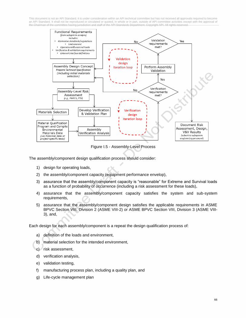
This document is not an API Standard; it is under consideration within an API technical committee but has not received all approvals required to become an API Standard. It shall not be reproduced or circulated or quoted, in whole or in part, outside of API committee activities except with the approval of the Chairman of the committee having jurisdiction and staff of the API Standards Department. Copyright API. All rights reserved.
66
Figure I.5 - Assembly-Level Process
The assembly/component design qualification process should consider:
1) design for operating loads,
2) the assembly/component capacity (equipment performance envelop),
3) assurance that the assembly/component capacity is “reasonable” for Extreme and Survival loads as a function of probability of occurrence (including a risk assessment for these loads),
4) assurance that the assembly/component capacity satisfies the system and sub-system requirements,
5) assurance that the assembly/component design satisfies the applicable requirements in ASME BPVC Section VIII, Division 2 (ASME VIII-2) or ASME BPVC Section VIII, Division 3 (ASME VIII-3), and,
Each design for each assembly/component is a repeat the design qualification process of:
a) definition of the loads and environment,
b) material selection for the intended environment,
c) risk assessment,
d) verification analysis,
e) validation testing,
f) manufacturing process plan, including a quality plan, and
g) Life-cycle management plan