for field use please distribute to the erection crew
TRANSCRIPT
DETAIL NAME IF APPLICABLEPart Number: H8430
PAGE 1
FOR FIELD USE
PLEASE DISTRIBUTE TO THE ERECTION CREW
DUE TO THE PROCESS OF CONTINUOUS IMPROVEMENT, THE PRODUCTS AND PROCEDURES IN THIS MANUAL ARE SUBJECT TO
CHANGE WITHOUT NOTICE

DETAIL NAME IF APPLICABLEPAGE 2
1.0 INTRODUCTION ...................................................................................................32.0 HANDLING PANELS AND COMPONENTS.........................................................4
2.1 Handling Panels and ComponeNts…Cont’d ....................................................................53.0 JOBSITE STORAGE.............................................................................................7
3.1 Job Site Storage… Cont’d................................................................................................83.2 Alignment & Shimming.....................................................................................................8
4.0 INSTALLATION TOOLS .......................................................................................95.0 FASTENERS .......................................................................................................106.0 INSTALLATION PROCEDURES ........................................................................117.0 INSTALLATION GUIDELINES............................................................................12
7.1 General Installation Guidelines ......................................................................................137.2 Butyl Tube Caulk at Perimeter Members: ......................................................................14
8.0 FIELD CUTTING..................................................................................................159.0 ACCESSORIES...................................................................................................1610.0 PANEL LAYOUT GUIDELINES..........................................................................1711.0 BASE ATTACHMENT.........................................................................................18
11.1 Base Attachment Cont’d ................................................................................................1912.0 HORIZONTALLY SPLICED PANELS.................................................................2013.0 OUTSIDE AND INSIDE CORNERS ....................................................................21
13.1 Outside and Inside Corners Cont’d ................................................................................2214.0 WALL OPENINGS...............................................................................................23
14.1 Wall openings Cont’d .....................................................................................................2414.2 Wall openings Cont’d .....................................................................................................25
15.0 SURFACE CLEANING PROCEDURES .............................................................2616.0 SURFACE REPAIR PROCEDURES...................................................................27

DETAIL NAME IF APPLICABLEPAGE 3
INSTALLATION INSTRUCTIONS1.0 INTRODUCTIONThe following pages are suggestions and guidelines for installation of 2’’ - 4’’ thick insulated wall panels. We believe that all of the information presented is accurate, but it is not intended to cover all instances, building designs or codes. (Note: Panels thicker than 4’’ and/or Cold Storage applications, require special details and considerations not addressed by these details).
Details supplied are proven methods of application; however it must be noted that ensuring water tightness is a function of the installer. The installer can assure water tightness by the professional application of the provided caulking and materials.
The job specific details may vary from project to project. Every installer shall familiarize himself with the all instructions, erection drawings and details before the application process begins.
Suggested procedures for the installer:
- Check all applicable federal, state and local codes to verify compliance with the code.
- Be certain that site conditions are such that safe working practices are strictly observed.
- Review all installation drawings and associated project documents.
- Consult with the General Contractor, Design Engineer, Architect and/or Owner to confirm those recommended.
- Comply with all safety regulations.
It is the responsibility of the designer / contractor / installer to ensure that the details and installation procedures are adapted to meet particular building requirements. The metal building/panel supplier shall not be held liable for any and all claims arising from lack of proper installation. The designer / installer must be aware of and allow for expansion and contraction of wall panels when designing and/or installing wall panels.
Some field cutting is part of normal erection work. Workmanship shall conform to the highest industry standards. A certain amount of waviness called “oil canning” may exist in the panel. Minor waviness is not sufficient cause for rejection and does not affect the structural integrity of the panel. Minimizing or elimination this effect can be accomplished by using simple industry standard procedures during surface preparation.
This Product Manual should be used as a supplement to the Job Erection Drawings.
The information in this product manual is subject to change without notice. The Metal Building/Panel Supplier reserves the right to discontinue or modify
products and installation procedures at any time. The latest version of this document should accompany your erection drawings.
Contact your Customer Service Coordinator for additional copies.

DETAIL NAME IF APPLICABLEPAGE 4
2.0 HANDLING PANELS AND COMPONENTS
Insulated panels are carefully inspected and bundled prior to loading for shipment. It is the responsibility of the transportation company to deliver these components undamaged. It is the consignee’s responsibility to inspect the shipment for damage and shortages when it is received.
When a shipment is received, check each item against the bill of lading for quantity, length, damage, etc. If a shortage or damage is found, make sure a notation of it is made on the bill of lading and signed by the driver. The manufacture cannot be responsible for shortages or damaged materials unless they are noted on the bill of landing.
In the case of packaged components (such as clips, fasteners, and sealants, ect.), the quantities are marked on their container and should be checked against the bill of materials.
It is the customer’s responsibility to make any damage claim. Immediately notify the designated customer service coordinator of any shortages or damaged materials. This will help to minimize any erection delays that may result from the shortage or damaged materials.
Upon arrival of panels, forklifts or hoisting equipment will be required to unload and position the panel bundles and accessory crates for jobsite storage and installation.
Extreme care should be taken to avoid bumping the panels while lifting and maneuvering. In all cases panels should not deflect significantly in the lifting process.
UNLOADING
Panels are spiral wrapped with stretch-film and shipped flat. Panel bundles are reinforced at specified lifting points to prevent damage when lifting.
Unloaders must take care that forklift forks are located at the particle board on the panel bundles before lifting.
Extreme care should be taken to avoid bumping or dropping the panels when lifting and maneuvering.
When unloading bundles of 36’-0” or longer in length, two or more lifting points may be required. Over engagement of forks will cause damage to the materials located on the opposite side of the bundle being lifted.
When an overhead crane is used, reinforced nylon slings or straps (no chains or cables should come in contact with the panels) should be used, along with suitably stiff inserts located at top and bottom of the bundles at the sling positions to protect the panels from damage.

DETAIL NAME IF APPLICABLEPAGE 5
2.1 HANDLING PANELS AND COMPONENTS…CONT’D
In handling panels individually, all personnel must wear the proper clothing, protective eye wear, and gloves. To help prevent damages to the surfaces and edges:
Always lift the panels when removing them from bundles, never drag them.
Never lift the panel from the flat position by the side joint or the overlapping rib.
Do not carry panels in the flat position.

DETAIL NAME IF APPLICABLEPAGE 6
The metal building/panel supplier does not take any responsibility for damage caused from mishandling of panels. Damaged panels shall be replaced or corrected to approval of the architect and any cost incurred shall be borne by the parties responsible for the damage.
Protective Plastic Film:Insulated panels and trims have a temporary protective plastic film on both sides of the panel. This film keeps the metal surface clean and helps prevent damage in shipping and handling.
This protective film is not to be removed from a panel until that panel is ready for installation on the jobsite. Strip protective film only from side joints and flashing areas before installing the panel and prior to installing sealant, clips, and fasteners. Then remove the protective film completely as soon as the area is completely installed. Protective film may need to be removed completely prior to installation if a suction type lifting system is used.
For best plastic film removal, start at a panel corner and pull off the protective plastic film at a 45 degree angle. Pull with even tension on the film to prevent tearing and to facilitate removal.
Note: Protective plastic film is not to be exposed to direct sunlight for more than 48 hours.
Prolonged exposure to direct sunlight and/or moisture will cause the plastic film to bond to the metal panel face. Once the plastic film has bonded to the metal surface, the removal of the plastic film
becomes very difficult. Therefore it is imperative to follow the jobsite handling and storing instructions. Store the panels properly in a dry location where they are covered from direct sunlight.

DETAIL NAME IF APPLICABLEPAGE 7
3.0 JOBSITE STORAGEUpon acceptance of the shipment, the customer is responsible for proper handling, storage, and security of the received materials. The manufacturer is not responsible for damage or loss of materials at the job site.
PANELS NOT REQUIRED FOR IMMEDIATE USE SHOULD BE:
- Carefully unloaded and placed directly in a protected storage area on a firm, level surface clear of debris, preferably under cover* and slit plastic wrap at base to allow air flow, for no longer than 30 days.
- Elevated with wood blocking, to allow air circulation under the bundle, on a firm, level surface clear of debris, standing water, direct sun, and drifting snow.
- Separate flat-laid bundles with the styrene dunnage from the shipment.
- Sloped at least 5 degrees for drainage of moisture from panels.
- Inspected daily for moisture, insure no sags are present. Trapped moisture can damage the panel finish and void applicable finish warranties. If panel bundles contain moisture or sags the panel bundle should be dried and restacked. Use care in restacking to avoid damage to panels.
Note: Protective plastic film is not to be exposed to direct sunlight for more than 48 hours.Prolonged exposure to direct sunlight will cause the plastic film to bond to the metal panel face. Once the plastic film has bonded to the metal surface, the removal of the plastic film becomes very difficult.
Therefore it is imperative to follow the jobsite handling and storing instructions. Store the panels properly in a dry location where they are covered from direct sunlight.

DETAIL NAME IF APPLICABLEPAGE 8
3.1 JOB SITE STORAGE… CONT’D
PANELS FOR IMMEDIATE USE:If the panels are to be used immediately, the bundles should be placed at pre-planned strategic locations around the perimeter of the building, as close as possible to the planned work areas, to avoid undue site maneuvering.
When moving panel bundles, extreme caution should be taken to prevent damage to the panel surfaces and edges.
When handling panels individually, they should be carried in a vertical, not flat position. Never drag panels when removing them from bundles.
NOTE: The plastic film protective covering should not be exposed to direct sunlight for more than 48 hours. Protective coating should not be removed until the panes are ready for erection at the jobsite.
(See “Handling Panels and Components”)
3.2 ALIGNMENT & SHIMMINGPrior to installation, wall secondary members should be checked for overall dimensions and evenness of plane. The wall secondary members should also be checked to verify the wall system can be installed without interference. Prior to installation of insulated panel, inspect each wall for component alignment and plane flatness. Wall components should not vary more that 3/16” over the entire wall surface, including fastener heads and other obstructions that would interfere with continuous bearing of the insulated panel liner face. Surface should not vary more than 1\4’’ over a 20’ length in any direction.Alignment at transition areas, such as corners and eave, shall be within 1\8’’ of the theoretical plane to accommodate corner panels and formed flashing.Misaligned secondary steel may require the erector to shim the insulated wall panels at some locations. Shims and labor for installing shims are not by the Metal Building Supplier.

DETAIL NAME IF APPLICABLEPAGE 9
4.0 INSTALLATION TOOLS
“Read before you start”
Sliding panels together will scuff, discolor or damage the finish.
It is important to note that, due to the hidden fastener side lap connections of these panels, extra care should be taken when handling these components.
The following is a list of common tool requirements. Refer to “Field Cutting” for panel cutting guidelines.
Wearing clean gloves, handling the panels by edges and taking a little extra care will pay off by producing a good clean finished wall.
Common Tool Requirements
1. Circular Saw
2. Power Drill
3. Carpenter’s Square
4. Rivet Gun
5. Level (4’ or 6’)
6. Chalk Line
7. Tape Measure
8. Caulk Gun
9. Screw Gun
10. Power Shears
11. Hammer Drill
12. Power Nibbler
CAUTION: Any Metal filings or burrs should be cleaned off the face of the panels as soon as possible to prevent rust from forming on the paint. (See “Cleaning Procedures”)
DETAIL NAME IF APPLICABLEGA2003.dwg
PAGE 10
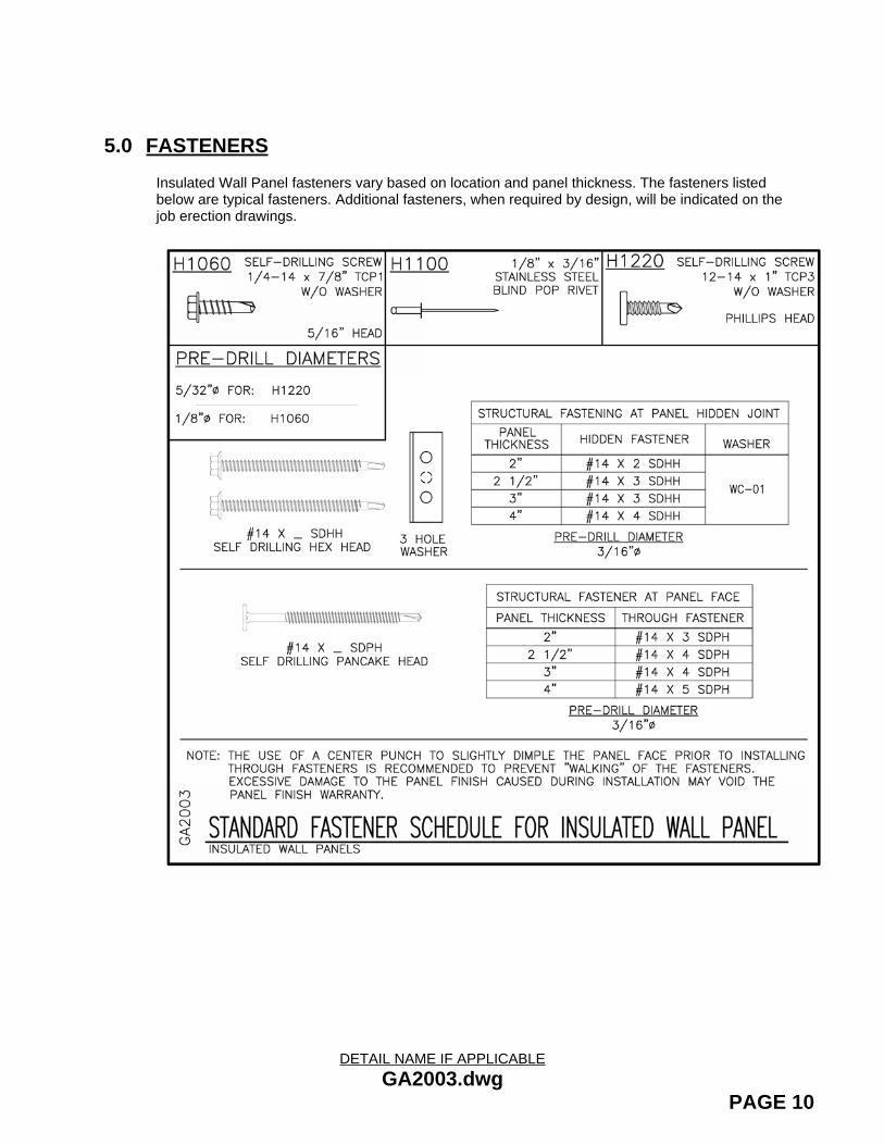
5.0 FASTENERSInsulated Wall Panel fasteners vary based on location and panel thickness. The fasteners listed below are typical fasteners. Additional fasteners, when required by design, will be indicated on the job erection drawings.

DETAIL NAME IF APPLICABLEPAGE 11
6.0 INSTALLATION PROCEDURESNOTE: Insulated panels, due to their joinery, do not provide diaphragm stiffness for the building wall to resist lateral forces including wind. Lateral bracing is to be provided by cross bracing systems connected to the primary building framing.
Prior to panel installation verify:Building Walls are Plumb: Insure building walls to be sheeted are plumb and that any cross-bracing required is in place and snug to prevent wall movement during panel installation. All secondary members are in place and plumb.
Minimum Girt Spacing: The minimum average girt spacing is ≥ 5’-0” along any given wall plane to minimize thermal restraining loads, and the resulting potential for delamination of the metal skin and internal insulation. For (3) or more spans, the average of all the spans should be used when checking against this minimum span length limit. (Example: if girt spacing on the wall is 3ft, 7ft, 6ft, & 4ft. The average spacing is 5’-0”, so no girts need to be skipped as a result).
Wall Plane is free of Obstructions - See “Installation Guidelines”
Panel layout - Review cut dimensions for insulated panels at erection drawing panellayouts and become familiar with starting and ending panel requirements.
Wall opening Locations - Locations of openings may need to be adjusted slightly (inches) due to panel joinery. Typically, panels above and below openings are to be installed as work progresses. If possible, keep side panel joints 6” away from framed openings as a minimum.
Personnel Walk Doors – Install prior to panel installation.
Notify your Customer Service Coordinator if you find a potential erection problem.
Once all of the above items have been verified, begin installation process:
1. To ensure a proper vapor barrier and water tightness, apply a 3/8” bead of butyl tube caulk at male edge of the panel if caulk is not present. Also, apply a continuous 3/8” bead of butyl tube caulk run at ALL perimeter support members; Base, Eave, Header, Sill, Horizontal Transitions, as shown in isometric detail at page 17. NOTE: This Caulk is not required at mid-span (intermediate) members, refer to detail at page 18.
2. Obtain first panel, if panel has protective plastic film, remove the film from panel edges only. Starting and ending panel cut dimension will be supplied on erection drawings. Refer to “Field Cutting”.
3. Place the first panel in the location as detailed on the sheeting drawings with the base of the first panel in the proper position, plumb the panel and secure in place.
4. Prepare adjacent panel edge (pull back film at sidelap, verify/add butyl caulk, etc.) place into position.
5. Maintain an even and uniform gap at the panel side joint (3/32” – 5/32”), then fasten panel into position using all required side joint fasteners. Refer to “Wall Openings” for specific information at openings.
6. Repeat the installation process occasionally checking for plumb. If any minor ‘out-of-plumb’ is detected, take corrective action in minor steps with subsequent panels to bring the sheeting process back to plumb.
Remove protective plastic films from installed panels once an area is completed and the surface protection provided by the film is no longer needed (refer to “Handling Panels and Components”).
DETAIL NAME IF APPLICABLEPAGE 12
7.0 INSTALLATION GUIDELINESInsulated panels provide insulation performance superior to conventional metal wall panels with field assembled insulation systems. The full energy savings potential can only be realized when the insulated panels are installed with careful attention to the details affecting the quality of air and moisture seal.
To ensure a proper vapor barrier and water tightness 3/8” bead of butyl caulk is required at locations indicated on the erection drawings. Sidelap caulk may be factory or field applied. It is however, the installers responsibility to field apply continuous butyl caulk at areas with voids or missing caulk. Continuity, size and proper bead placement are critical in obtaining a satisfactory seal at each panel edge. Details for placement of caulk at panel edges should be reviewed in advance. Application of caulk should be continuous.
Special care in handling is required to prevent damage or contamination by field debris within the panel side joint. All secondary support steel should be in place for continuous attachment of panels across the surface of primary framing members, including outer extremes of corners, openings, gables, etc.
Panel Engagement at side joints should be as indicated on details.
Prior to installation of insulated panel, inspect each wall for component alignment and plane flatness. Wall components should not vary more that 3/16” over the entire wall surface, including fastener heads and other obstructions that would interfere with continuous bearing of the insulated panel liner face. Surface should not vary more than 1\4’’ over a 20’ length in any direction.
Alignment at transition areas, such as corners and eave, shall be within 1\8’’ of the theoretical plane to accommodate corner panels and formed flashing.
Misaligned secondary steel may require the erector to shim the insulated wall panels at some locations. Shims and labor for installing shims are not by the Metal Building Supplier.
Do Not Overdrive Fasteners: Overdriving fasteners can cause damage and distortion of the panel face.
Do Not Skip Attachments at Secondary Support Members: Panels must be attached at each girt line in progression. Securing panels at top and bottom only can cause panels to bow and it might be impossible for them to return to their normal position.
At the base of wall panels in all conditions, a bead of marriage caulk should be applied from the vertical seam caulk, to the top of the trim covering the base of the panels. This is done to direct water flow to the exterior of the building, and avoid interior leaks. (See erection details for additional information).

DETAIL NAME IF APPLICABLEGA2001.dwg
PAGE 13
7.1 GENERAL INSTALLATION GUIDELINES

DETAIL NAME IF APPLICABLEPAGE 14
7.2 BUTYL TUBE CAULK AT PERIMETER MEMBERS:
Continuous Butyl Tube Caulk, (H3151) is required at allperimeter members.
Horizontal locations as shown, include: Base, Eave, Header, Sill, Panel End Transitions, Framed Openings and areas adjacent to panel cut edge.
Vertical locations, as indicated on erection drawings include: Corners (at each wall plane), Jambs, Panel Transitions and areas adjacent to panel cut edges.
Perimeter caulking shown with dashed lines

DETAIL NAME IF APPLICABLEPAGE 15
8.0 FIELD CUTTINGSome field cutting of panels and flashing will be required. It is the workers responsibility to make sure all safety precautions are followed. Some safety precautions include, but are not limited to; Eye protection, adequate ventilation, No smoking and avoid exposing panels to high heat.
Panels are to be cut one metal side at a time and the insulation can be removed with a utility knife or the blade of a carpenter’s handsaw. A circular saw with an appropriate blade set to cut through the metal skin only can be used. Circular saws with abrasive blades are not expectable. Be sure to cut completely through the metal skin at the panel side joints. A circular saw with a proper carbide blade may be used. Check the saw blade manufactures’ specifications for proper application.
Recommended cutting tools include: (1) Circular Saw
(2) Panel Nibbler
(3) Panel Saw
(4) Utility Knife
(5) Blade of a carpenter’s hand saw
- Always promptly clean panel surfaces to remove any metal dust or filings from cutting operations.
- Field-cut edges should always be covered with trims.
The panel/bldg. manufacturer (MBS) will not be responsible for damage to panels caused by improper cutting methods.
- Never use a reciprocating saw to cut insulated panels. Reciprocating saws can cause structural damage to the insulated panels by delaminating the panel face metal from the foam core material.
- Never use any type of torch to cut insulated panel.
- Never subject an insulated panel to the heat of a torch even when cutting nearby steel. High heat will damage the panel finish and can cause the foam core to produce fumes which may be irritating to some individuals.
- Never burn remnants, dispose of insulated panel remnants by depositing in proper garbage facilities.

DETAIL NAME IF APPLICABLEPAGE 16
9.0 ACCESSORIES Trims lengths supplied will vary and may require some field cutting.
Trim color availability matches panel color availability.
ALL trims will be supplied in a smooth finish, 26 ga material.
TRIM ATTACHMENT
Exterior trims are fastened with blind rivets or stitch screws, painted to match trim color. Refer to the cad details and the erection drawings for locations and fastening spacing.
Interior trims (IF REQUIRED) are fastened with Regal White (panel inside color is imperial white) painted blind rivets or stitch screws, painted to match trim color. Refer to the cad details and the erection drawings for locations and fastening spacing
THERMAL WINDOW
Due to the isolative properties and connection requirements of the wall system, only thermal break windows are recommended for use with insulated wall panels.

DETAIL NAME IF APPLICABLEGA2007.dwg
PAGE 17
10.0PANEL LAYOUT GUIDELINESThe details associated with these panels have been developed using the standard left to right installation. (Right to left installation may be accomplished by flipping the panels over and reversing this method.)
Field cutting is required to obtain a closed corner by removing the joint of the panel. Erection drawings will contain panel layouts indicating the starting and ending panel cut back dimensions. Locations of field located openings may need to be adjusted slightly to ensure that opening jambs are a minimum of 6”.Panels at headers and sills will need to be field cut prior to installation to allow for flashing installations.
Starting at a corner, with the required caulk applied at support members, place the first panel into position, plumb and fasten to all support members in order. Place the second panel into position so the bottom corner of second panel joint engages the first panel then push until joint fully engages. Check to ensure that the panel is square and level and gap is reduced to 0.04’’.

DETAIL NAME IF APPLICABLEGB2300.dwg
PAGE 18
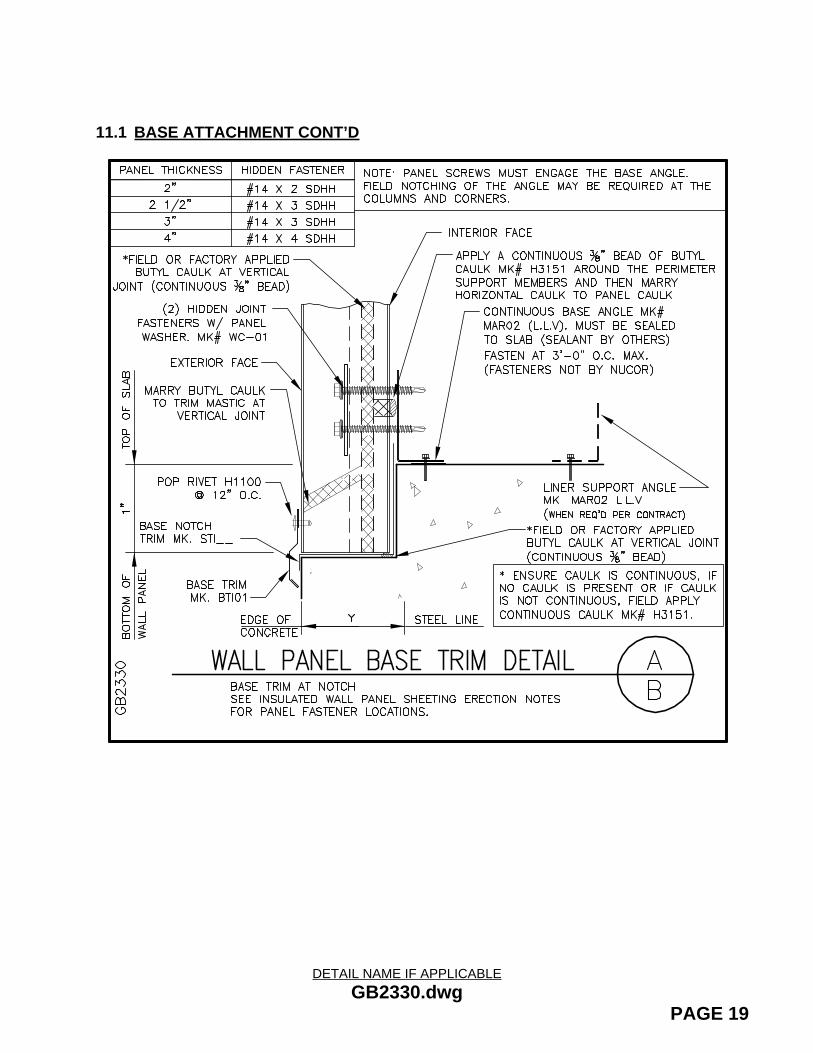
11.0BASE ATTACHMENTPrior to panel installation install and seal base member. (sealant by others) Typical base conditions are as shown below, however, always refer to erection drawing details for job specific connection requirements.
DETAIL NAME IF APPLICABLEGB2330.dwg
PAGE 19
11.1 BASE ATTACHMENT CONT’D

DETAIL NAME IF APPLICABLEGA2042.dwg
PAGE 20
12.0HORIZONTALLY SPLICED PANELSHorizontal splices will be required when maximum panel length is exceeded or for other job specific applications, such as two color wall panel applications.The attachment of the horizontal splice, or stack joint should be installed as shown on the erection drawing details. Typical installation is as follows:Procedure:
1. Install the bottom course of panels applying caulk and inserting fasteners as required.
2. Apply a continuous horizontal run of butyl caulk on the top of the lower panel.
3. Next apply a bead of butyl caulk to the support angle.
4. Set Stacking trim in place. Temporarily fasten to angle with pop rivets.
5. Apply a continuous horizontal run of butyl caulk onto the top leg of the stacking trim and marry to the vertical caulk at panel side joints.
5. Install the top course of panels applying caulks and inserting fasteners as required.
6. Cover cut edge of panel with Panel End Cover Trim and attach per erection drawings.

DETAIL NAME IF APPLICABLEGC2021.dwg
PAGE 21
13.0OUTSIDE AND INSIDE CORNERSInstall support members and a continuous ¼’’ bead of butyl caulk as indicated on erection drawings. Field cut panels as required at locations shown on erection drawings. Fill in gaps with loose insulation. (N.I.C.) Typically, both outside and inside corners attach with through fasteners. NOTE: The use of center punch to slightly dimple the panel face prior to the installation of the Through Fasteners is recommended to prevent “walking” of the fasteners. Excessive damage to the panel finish caused during installation may void the panel finish warranty.A continuous bead of butyl caulk is applied vertically at each leg of the corner flashing. Trims attach to wall panels at each side of the corner with 1/8’’ blind rivets. Field touch up of rivets maybe required after installation. OUTSIDE CORNER:

DETAIL NAME IF APPLICABLEGC2051.dwg
PAGE 22
13.1 OUTSIDE AND INSIDE CORNERS CONT’D
INSIDE CORNER:

DETAIL NAME IF APPLICABLEPAGE 23
14.0WALL OPENINGSStandard wall openings do not change because of the insulated wall system. However, insulated panels will require a little extra preparation and consideration. Panels bordering openings of accessories must be field cut. (See “Field Cutting”) as sheeting progresses.
Install openings in accordance with erection drawing details.
Field located openings may require a slight location adjustment for attachment at sidelap. It is recommended that whenever possible maintain 6’’ minimum edge distance for panel sidelaps as indicated below.
NOTE: Remember to apply perimeter caulk (H3151) around all framed openings prior to installing panels.

DETAIL NAME IF APPLICABLEGD2020.dwg GD2040.dwg
PAGE 24
14.1 WALL OPENINGS CONT’D
JAMB CONNECTION:
HEADER CONNECTION:

DETAIL NAME IF APPLICABLEGD2070.dwg
PAGE 25
14.2 WALL OPENINGS CONT’D
SILL CONNECTION:

DETAIL NAME IF APPLICABLEPAGE 26
15.0SURFACE CLEANING PROCEDURESGENERAL
Dirt, oil, grease, fingerprints or any other type on contaminate must be completely removed when installation is complete in order to maximize coating performance.
Steel filings from adjacent work may become embedded in the paint surface. These filings will rust and form unsightly red spots on the painted surface that can become larger than the original filing. When using saws, drills or cutting discs, protect the painted surfaced with a non-flammable cover and remove or cover adjacent or nearby panels if possible.
Brush any filings of steel off the painted surface. Embedded filings should be removed mechanically. Care should be taken by workmen to avoid stepping on or exerting pressure against any steel filings which may become embedded in the painted surface.
Things to remember when cleaning:
Use only mild detergents (No lemon, alcohol or ammonia ingredients)
Use only soft bristle brushes (No scrub type or wire bristles)
Use only lukewarm water (No hot water)
Light or periodic cleaning may be accomplished on a regular basis by washing with plain water using a standard garden hose or low pressure sprayer is usually sufficient to remove most contamination.
Caulking compounds, oil, grease, tars, wax and similar substances can be removed by wiping with a cloth soaked in mineral spirits. Wipe only contaminated areas and follow with detergent and thorough clear water rinse.

DETAIL NAME IF APPLICABLEPAGE 27
16.0SURFACE REPAIR PROCEDURESIf “touch up” paint is required contact your Metal Building Supplier customer service coordinator.
Precautions:
Protect eyes, face, and hands from direct contact with touch-up paint and/or solvents.
Provide good ventilation in work area. Enforce NO SMOKING. Remove all sources of ignition.
These coatings and solvents are FLAMMABLE.
1. Lightly sand or feather edges of deep scratches using #400 grit sand paper
2. Wipe scratches and adjacent areas using a lint free cloth dampened in mineral spirits.
3. Allow area to dry thoroughly before applying touch-up paint.
4. Shake and stir paint to mix thoroughly before applying.
5. Check touch-up paint for correct match before applying.
6. Apply thin layer of touch-up paint to damaged area. Repeat layers as required.