for modules with firmware version 1 - sparkfun...
TRANSCRIPT

Part Number 68340-00Revision A
September 2009
Copernicus® II GPS ReceiverReference Manual
For Modules with Firmware Version 1.05
Corporate Office
Trimble Navigation Limited935 Stewart DriveSunnyvale, CA 94085U.S.A.Phone: +1-408-481-8000, 1-800-827-8000www.trimble.com
Support
+1-800-767-4822 (USA and Canada)+1-913-338-8225 (International)
Copyright and Trademarks
© 2009 Trimble Navigation Limited. All rights reserved. No part of this manual may be copied, reproduced, translated, or reduced to any electronic medium or machine-readable form for any use other than with the Copernicus II® GPS Receiver.
The Globe & Triangle logo, Trimble, Colossus, FirstGPS, Lassen, Copernicus, and Copernicus II are trademarks of Trimble Navigation Limited.
The Sextant logo with Trimble is a trademark of Trimble Navigation Limited, registered in the United States Patent and Trademark Office.
All other trademarks are the property of their respective owners.
Release Notice
This is the November 2008 release (Revision A) of the Copernicus II® GPS Receiver System Designer Reference Manual, part number 58052-20.
The following limited warranties give you specific legal rights. You may have others, which vary from state/jurisdiction to state/jurisdiction.
Waste Electrical and Electronic Equipment (WEEE) Notice
This Trimble product is furnished on an OEM basis. By incorporating this Trimble product with your finished goods product(s) you shall be deemed the “producer” of all such products under any laws, regulations or other statutory scheme providing for the marking, collection, recycling and/or disposal of electrical and electronic equipment (collectively, “WEEE Regulations”) in any jurisdiction whatsoever, (such as for example national laws implementing EC Directive 2002/96 on waste electrical and electronic equipment, as amended), and shall be solely responsible for complying with all such applicable WEEE Regulations.
Restriction on Hazardous Substances
As of July 1, 2006, the Product is compliant in all material respects with DIRECTIVE 2002/95/EC OF THE EUROPEAN PARLIAMENT AND OF THE COUNCIL of 27 January 2003 on the restriction of the use of certain hazardous substances in electrical and electronic equipment (RoHS Directive) and Amendment 2005/618/EC filed under C(2005) 3143, with exemptions for lead in solder pursuant to Paragraph 7 of the Annex to the RoHS Directive applied. The foregoing is limited to Product placed on the market in the Member States of the European Union on or after 1 July 2006. Trimble has relied on representations made by its suppliers in certifying this Product as RoHS compliant.
Hardware Limited Warranty
Trimble warrants that this Trimble hardware product (the “Product”) shall be free from defects in materials and workmanship and will substantially conform to Trimble’s applicable published specifications for the Product for a period of one (1) year, starting from the date of delivery. The warranty set forth in this paragraph shall not apply to software/firmware products.
Software and Firmware License, Limited Warranty
This Trimble software and/or firmware product (the “Software”) is licensed and not sold. Its use is governed by the provisions of the applicable End User License Agreement (“EULA”), if any, included with the Software. In the absence of a separate EULA included with the Software providing different limited warranty terms, exclusions, and limitations, the following terms and conditions shall apply. Trimble warrants that this Trimble Software product will substantially conform to Trimble’s applicable published specifications for the Software for a period of ninety (90) days, starting from the date of delivery.
Warranty Remedies
Trimble's sole liability and your exclusive remedy under the warranties set forth above shall be, at Trimble’s option, to repair or replace any Product or Software that fails to conform to such warranty (“Nonconforming Product”), or refund the purchase price paid by you for any such Nonconforming Product, upon your return of any Nonconforming Product to Trimble in accordance with Trimble’s standard return material authorization procedures.

Warranty Exclusions and Disclaimer
These warranties shall be applied only in the event and to the extent that: (i) the Products and Software are properly and correctly installed, configured, interfaced, maintained, stored, and operated in accordance with Trimble’s relevant operator's manual and specifications, and; (ii) the Products and Software are not modified or misused.
The preceding warranties shall not apply to, and Trimble shall not be responsible for defects or performance problems resulting from (i) the combination or utilization of the Product or Software with products, information, data, systems or devices not made, supplied or specified by Trimble; (ii) the operation of the Product or Software under any specification other than, or in addition to, Trimble's standard specifications for its products; (iii) the unauthorized modification or use of the Product or Software; (iv) damage caused by accident, lightning or other electrical discharge, fresh or salt water immersion or spray; or (v) normal wear and tear on consumable parts (e.g., batteries).
THE WARRANTIES ABOVE STATE TRIMBLE'S ENTIRE LIABILITY, AND YOUR EXCLUSIVE REMEDIES, RELATING TO PERFORMANCE OF THE PRODUCTS AND SOFTWARE. EXCEPT AS OTHERWISE EXPRESSLY PROVIDED HEREIN, THE PRODUCTS, SOFTWARE, AND ACCOMPANYING DOCUMENTATION AND MATERIALS ARE PROVIDED “AS-IS” AND WITHOUT EXPRESS OR IMPLIED WARRANTY OF ANY KIND BY EITHER TRIMBLE NAVIGATION LIMITED OR ANYONE WHO HAS BEEN INVOLVED IN ITS CREATION, PRODUCTION, INSTALLATION, OR DISTRIBUTION, INCLUDING, BUT NOT LIMITED TO, THE IMPLIED WARRANTIES OF MERCHANTABILITY AND FITNESS FOR A PARTICULAR PURPOSE, TITLE, AND NONINFRINGEMENT. THE STATED EXPRESS WARRANTIES ARE IN LIEU OF ALL OBLIGATIONS OR LIABILITIES ON THE PART OF TRIMBLE ARISING OUT OF, OR IN CONNECTION WITH, ANY PRODUCTS OR SOFTWARE. SOME STATES AND JURISDICTIONS DO NOT ALLOW LIMITATIONS ON DURATION OR THE EXCLUSION OF AN IMPLIED WARRANTY, SO THE ABOVE LIMITATION MAY NOT APPLY TO YOU.
TRIMBLE NAVIGATION LIMITED IS NOT RESPONSIBLE FOR THE OPERATION OR FAILURE OF OPERATION OF GPS SATELLITES OR THE AVAILABILITY OF GPS SATELLITE SIGNALS.
Limitation of Liability
TRIMBLE’S ENTIRE LIABILITY UNDER ANY PROVISION HEREIN SHALL BE LIMITED TO THE GREATER OF THE AMOUNT PAID BY YOU FOR THE PRODUCT OR SOFTWARE LICENSE OR U.S.$25.00. TO THE MAXIMUM EXTENT PERMITTED BY APPLICABLE LAW, IN NO EVENT SHALL TRIMBLE OR ITS SUPPLIERS BE LIABLE FOR ANY INDIRECT, SPECIAL, INCIDENTAL, OR CONSEQUENTIAL DAMAGES WHATSOEVER UNDER ANY CIRCUMSTANCE OR LEGAL THEORY RELATING IN ANY WAY TO THE PRODUCTS, SOFTWARE, AND ACCOMPANYING DOCUMENTATION AND MATERIALS, (INCLUDING, WITHOUT LIMITATION, DAMAGES FOR LOSS OF BUSINESS PROFITS, BUSINESS INTERRUPTION, LOSS OF BUSINESS INFORMATION, OR ANY OTHER PECUNIARY LOSS), REGARDLESS OF WHETHER TRIMBLE HAS BEEN ADVISED OF THE POSSIBILITY OF ANY SUCH LOSS AND REGARDLESS OF THE COURSE OF DEALING WHICH DEVELOPS OR HAS DEVELOPED BETWEEN YOU AND TRIMBLE. BECAUSE SOME STATES AND JURISDICTIONS DO NOT ALLOW THE EXCLUSION OR LIMITATION OF LIABILITY FOR CONSEQUENTIAL OR INCIDENTAL DAMAGES, THE ABOVE LIMITATION MAY NOT APPLY TO YOU.

Table of Contents 1
1 STARTER KITIntroduction . . . . . . . . . . . . . . . . . . . . . . . . . . . . . . . . . . . . . . . . . . . . . . 6
Starter Kit Components . . . . . . . . . . . . . . . . . . . . . . . . . . . . . . . . . . . . 6Interface Unit . . . . . . . . . . . . . . . . . . . . . . . . . . . . . . . . . . . . . . . . . . . . . 7Interface Connections . . . . . . . . . . . . . . . . . . . . . . . . . . . . . . . . . . . . . . . . . 9
Removing the Reference Board from the Interface Unit. . . . . . . . . . . . . . . . . . . 11Antenna . . . . . . . . . . . . . . . . . . . . . . . . . . . . . . . . . . . . . . . . . . . . . . . 12
Using a Passive Antenna . . . . . . . . . . . . . . . . . . . . . . . . . . . . . . . . . . . 12Quick Start Guide . . . . . . . . . . . . . . . . . . . . . . . . . . . . . . . . . . . . . . . . . . 13Trimble GPS Studio. . . . . . . . . . . . . . . . . . . . . . . . . . . . . . . . . . . . . . . . . 15
Installing the FTDI USB/Serial Driver Software. . . . . . . . . . . . . . . . . . . . . . . 15Connect the PC via the USB serial interface. . . . . . . . . . . . . . . . . . . . . . . . . 16Start the TGS Application . . . . . . . . . . . . . . . . . . . . . . . . . . . . . . . . . . 18Connect to the GPS Receiver . . . . . . . . . . . . . . . . . . . . . . . . . . . . . . . . 19Configure the GPS Ports . . . . . . . . . . . . . . . . . . . . . . . . . . . . . . . . . . . 20Configure the Output Formats . . . . . . . . . . . . . . . . . . . . . . . . . . . . . . . . 22Configure GPS . . . . . . . . . . . . . . . . . . . . . . . . . . . . . . . . . . . . . . . . 23Configure PPS Output . . . . . . . . . . . . . . . . . . . . . . . . . . . . . . . . . . . . 24Configure NMEA Output . . . . . . . . . . . . . . . . . . . . . . . . . . . . . . . . . . 25Configure TAIP Output . . . . . . . . . . . . . . . . . . . . . . . . . . . . . . . . . . . 26Create a Log . . . . . . . . . . . . . . . . . . . . . . . . . . . . . . . . . . . . . . . . . 27Sending Raw Data to Device. . . . . . . . . . . . . . . . . . . . . . . . . . . . . . . . . 28Data Converter Tool . . . . . . . . . . . . . . . . . . . . . . . . . . . . . . . . . . . . . 30
2 PRODUCT DESCRIPTIONKey Features . . . . . . . . . . . . . . . . . . . . . . . . . . . . . . . . . . . . . . . . . . . . 34
Block Diagram . . . . . . . . . . . . . . . . . . . . . . . . . . . . . . . . . . . . . . . . 35Specifications . . . . . . . . . . . . . . . . . . . . . . . . . . . . . . . . . . . . . . . . . . . . 36
Performance . . . . . . . . . . . . . . . . . . . . . . . . . . . . . . . . . . . . . . . . . 36Interface . . . . . . . . . . . . . . . . . . . . . . . . . . . . . . . . . . . . . . . . . . . 37Electrical . . . . . . . . . . . . . . . . . . . . . . . . . . . . . . . . . . . . . . . . . . . 37Physical. . . . . . . . . . . . . . . . . . . . . . . . . . . . . . . . . . . . . . . . . . . . 37Environmental . . . . . . . . . . . . . . . . . . . . . . . . . . . . . . . . . . . . . . . . 37
Absolute Minimum and Maximum Limits . . . . . . . . . . . . . . . . . . . . . . . . . . . . . 38Normal Operating Conditions. . . . . . . . . . . . . . . . . . . . . . . . . . . . . . . . . . . . 39Power Consumption Over Temperature and Voltage . . . . . . . . . . . . . . . . . . . . . . . . 40
Run Mode . . . . . . . . . . . . . . . . . . . . . . . . . . . . . . . . . . . . . . . . . . 40ESD Protection . . . . . . . . . . . . . . . . . . . . . . . . . . . . . . . . . . . . . . . . . . . 40Ordering Information . . . . . . . . . . . . . . . . . . . . . . . . . . . . . . . . . . . . . . . . 41
Copernicus II GPS Receiver 1

3 INTERFACE CHARACTERISTICSPin Assignments . . . . . . . . . . . . . . . . . . . . . . . . . . . . . . . . . . . . . . . . . . 44Pin Description . . . . . . . . . . . . . . . . . . . . . . . . . . . . . . . . . . . . . . . . . . . 45
Detailed Pin Descriptions . . . . . . . . . . . . . . . . . . . . . . . . . . . . . . . . . . 46Protocols . . . . . . . . . . . . . . . . . . . . . . . . . . . . . . . . . . . . . . . . . . . 48
Serial Port Default Settings . . . . . . . . . . . . . . . . . . . . . . . . . . . . . . . . . . . . . 49GPS Timing . . . . . . . . . . . . . . . . . . . . . . . . . . . . . . . . . . . . . . . . . . . . . 50
Serial Time Output . . . . . . . . . . . . . . . . . . . . . . . . . . . . . . . . . . . . . . 50A-GPS. . . . . . . . . . . . . . . . . . . . . . . . . . . . . . . . . . . . . . . . . . . . . . . . 52
Enabling A-GPS with the Trimble GPS Studio Application (TGS) . . . . . . . . . . . . . 52Enabling A-GPS with TSIP . . . . . . . . . . . . . . . . . . . . . . . . . . . . . . . . . 53
Pulse-Per-Second (PPS). . . . . . . . . . . . . . . . . . . . . . . . . . . . . . . . . . . . . . . 54Stationary Mode . . . . . . . . . . . . . . . . . . . . . . . . . . . . . . . . . . . . . . . 54
4 OPERATING MODESCopernicus II GPS Receiver Operating Modes . . . . . . . . . . . . . . . . . . . . . . . . . . . 56
Run Mode . . . . . . . . . . . . . . . . . . . . . . . . . . . . . . . . . . . . . . . . . . 56Standby Mode . . . . . . . . . . . . . . . . . . . . . . . . . . . . . . . . . . . . . . . . 56Monitor Mode . . . . . . . . . . . . . . . . . . . . . . . . . . . . . . . . . . . . . . . . 56
Changing the Run/Standby Modes . . . . . . . . . . . . . . . . . . . . . . . . . . . . . . . . . 57Copernicus II GPS Receiver Standby Current . . . . . . . . . . . . . . . . . . . . . . . . 57Using the XSTANDBY Pin to Switch Modes . . . . . . . . . . . . . . . . . . . . . . . . 58Using Serial Ports to Switch Modes . . . . . . . . . . . . . . . . . . . . . . . . . . . . . 58
Saving Almanac, Ephemeris and Position to Flash Memory . . . . . . . . . . . . . . . . . . . . 60Graceful Shutdown. . . . . . . . . . . . . . . . . . . . . . . . . . . . . . . . . . . . . . 60
SBAS . . . . . . . . . . . . . . . . . . . . . . . . . . . . . . . . . . . . . . . . . . . . . . . . 60WAAS . . . . . . . . . . . . . . . . . . . . . . . . . . . . . . . . . . . . . . . . . . . . . . . . 60
Number of channels . . . . . . . . . . . . . . . . . . . . . . . . . . . . . . . . . . . . . 60Acquisition . . . . . . . . . . . . . . . . . . . . . . . . . . . . . . . . . . . . . . . . . . 61Usage . . . . . . . . . . . . . . . . . . . . . . . . . . . . . . . . . . . . . . . . . . . . . 61Almanac collection. . . . . . . . . . . . . . . . . . . . . . . . . . . . . . . . . . . . . . 61Ephemeris collection . . . . . . . . . . . . . . . . . . . . . . . . . . . . . . . . . . . . . 61
GPS Receiver Acquisition Sensitivity Mode . . . . . . . . . . . . . . . . . . . . . . . . . . . . 61
5 APPLICATION CIRCUITSPassive Antenna—Minimum Connections . . . . . . . . . . . . . . . . . . . . . . . . . . . . . 64Passive Antenna—Hardware Activated Standby . . . . . . . . . . . . . . . . . . . . . . . . . . 65Active Antenna—Full Connection . . . . . . . . . . . . . . . . . . . . . . . . . . . . . . . . . 66Active Antenna—Short Circuit Connection . . . . . . . . . . . . . . . . . . . . . . . . . . . . 68Active Antenna—No Antenna Status . . . . . . . . . . . . . . . . . . . . . . . . . . . . . . . . 70
2 Copernicus II GPS Receiver

6 RF LAYOUT CONSIDERATIONSGeneral Recommendations . . . . . . . . . . . . . . . . . . . . . . . . . . . . . . . . . . . . . 72Design considerations for RF Track Topologies . . . . . . . . . . . . . . . . . . . . . . . . . . 74 PCB Considerations . . . . . . . . . . . . . . . . . . . . . . . . . . . . . . . . . . . . . . . . 75
Microstrip Transmission Lines. . . . . . . . . . . . . . . . . . . . . . . . . . . . . . . . 75Stripline Transmission Lines . . . . . . . . . . . . . . . . . . . . . . . . . . . . . . . . . 77
7 MECHANICAL SPECIFICATIONSMechanical Outline Drawing . . . . . . . . . . . . . . . . . . . . . . . . . . . . . . . . . . . . 80Soldering the Copernicus II GPS Receiver to a PCB . . . . . . . . . . . . . . . . . . . . . . . . 81
Solder mask . . . . . . . . . . . . . . . . . . . . . . . . . . . . . . . . . . . . . . . . . 81Pad Pattern . . . . . . . . . . . . . . . . . . . . . . . . . . . . . . . . . . . . . . . . . . 82Paste Mask . . . . . . . . . . . . . . . . . . . . . . . . . . . . . . . . . . . . . . . . . . 83
8 PACKAGINGIntroduction . . . . . . . . . . . . . . . . . . . . . . . . . . . . . . . . . . . . . . . . . . . . . 86Reel . . . . . . . . . . . . . . . . . . . . . . . . . . . . . . . . . . . . . . . . . . . . . . . . . 87Tapes . . . . . . . . . . . . . . . . . . . . . . . . . . . . . . . . . . . . . . . . . . . . . . . . 88
9 SHIPPING AND HANDLINGShipping and Handling Guidelines . . . . . . . . . . . . . . . . . . . . . . . . . . . . . . . . . 90
Handling . . . . . . . . . . . . . . . . . . . . . . . . . . . . . . . . . . . . . . . . . . . 90Shipment . . . . . . . . . . . . . . . . . . . . . . . . . . . . . . . . . . . . . . . . . . . 90Storage . . . . . . . . . . . . . . . . . . . . . . . . . . . . . . . . . . . . . . . . . . . . 90Moisture Indicator . . . . . . . . . . . . . . . . . . . . . . . . . . . . . . . . . . . . . . 90Floor Life. . . . . . . . . . . . . . . . . . . . . . . . . . . . . . . . . . . . . . . . . . . 90
Moisture Precondition . . . . . . . . . . . . . . . . . . . . . . . . . . . . . . . . . . . . . . . 91Baking Procedure . . . . . . . . . . . . . . . . . . . . . . . . . . . . . . . . . . . . . . . . . . 92Soldering Paste . . . . . . . . . . . . . . . . . . . . . . . . . . . . . . . . . . . . . . . . . . . 92Solder Reflow . . . . . . . . . . . . . . . . . . . . . . . . . . . . . . . . . . . . . . . . . . . . 92Recommended Soldering Profile . . . . . . . . . . . . . . . . . . . . . . . . . . . . . . . . . . 93Optical Inspection . . . . . . . . . . . . . . . . . . . . . . . . . . . . . . . . . . . . . . . . . . 93Cleaning. . . . . . . . . . . . . . . . . . . . . . . . . . . . . . . . . . . . . . . . . . . . . . . 94Soldering Guidelines . . . . . . . . . . . . . . . . . . . . . . . . . . . . . . . . . . . . . . . . 94
Repeated Reflow Soldering . . . . . . . . . . . . . . . . . . . . . . . . . . . . . . . . . 94Wave Soldering . . . . . . . . . . . . . . . . . . . . . . . . . . . . . . . . . . . . . . . 94Hand Soldering. . . . . . . . . . . . . . . . . . . . . . . . . . . . . . . . . . . . . . . . 94
Rework . . . . . . . . . . . . . . . . . . . . . . . . . . . . . . . . . . . . . . . . . . . . . . . 94Conformal Coating . . . . . . . . . . . . . . . . . . . . . . . . . . . . . . . . . . . . . . . . . 94Grounding the Metal Shield. . . . . . . . . . . . . . . . . . . . . . . . . . . . . . . . . . . . . 95
Copernicus II GPS Receiver 3

10 COPERNICUS II REFERENCE BOARDIntroduction . . . . . . . . . . . . . . . . . . . . . . . . . . . . . . . . . . . . . . . . . . . . . 98Reference Board Block Diagram . . . . . . . . . . . . . . . . . . . . . . . . . . . . . . . . . . 99Reference Board Schematic (1 of 3) . . . . . . . . . . . . . . . . . . . . . . . . . . . . . . . .100Reference Board Schematic (2 of 3) . . . . . . . . . . . . . . . . . . . . . . . . . . . . . . . .101Reference Board Schematic (3 of 3) . . . . . . . . . . . . . . . . . . . . . . . . . . . . . . . .102Reference Board I/O and Power Connector . . . . . . . . . . . . . . . . . . . . . . . . . . . .103Reference Board Power Requirement. . . . . . . . . . . . . . . . . . . . . . . . . . . . . . . .103Reference Board Component Locations Drawing . . . . . . . . . . . . . . . . . . . . . . . . .104
11 FIRMWARE UPLOADSoftware Architecture . . . . . . . . . . . . . . . . . . . . . . . . . . . . . . . . . . . . . . . .106Boot Monitor . . . . . . . . . . . . . . . . . . . . . . . . . . . . . . . . . . . . . . . . . . . .106Firmware Binary File Format . . . . . . . . . . . . . . . . . . . . . . . . . . . . . . . . . . . .107Firmware Loading Procedure . . . . . . . . . . . . . . . . . . . . . . . . . . . . . . . . . . . .107
Pseudo-code . . . . . . . . . . . . . . . . . . . . . . . . . . . . . . . . . . . . . . . . .107Pseudo-Code Explanation . . . . . . . . . . . . . . . . . . . . . . . . . . . . . . . . . .109Error Recovery . . . . . . . . . . . . . . . . . . . . . . . . . . . . . . . . . . . . . . . . 111
Monitor Interface Protocol . . . . . . . . . . . . . . . . . . . . . . . . . . . . . . . . . . . . . 111Protocol Format . . . . . . . . . . . . . . . . . . . . . . . . . . . . . . . . . . . . . . . 111Data Transmission . . . . . . . . . . . . . . . . . . . . . . . . . . . . . . . . . . . . . . 111Monitor Mode Packet Descriptions . . . . . . . . . . . . . . . . . . . . . . . . . . . . . 112ENQ, ACK, NAK . . . . . . . . . . . . . . . . . . . . . . . . . . . . . . . . . . . . . . 112Packet ID – 0x96 (Boot ROM Version Report) . . . . . . . . . . . . . . . . . . . . . . . 112Packet ID – 0x8F (Erase Firmware Section). . . . . . . . . . . . . . . . . . . . . . . . . 113
FlashLoader Tool Reference Guide . . . . . . . . . . . . . . . . . . . . . . . . . . . . . . . . . 116Introduction . . . . . . . . . . . . . . . . . . . . . . . . . . . . . . . . . . . . . . . . . 116File and Folder Structure . . . . . . . . . . . . . . . . . . . . . . . . . . . . . . . . . . . 116Source Code Reference . . . . . . . . . . . . . . . . . . . . . . . . . . . . . . . . . . . 116Compiling and Generating the Executable. . . . . . . . . . . . . . . . . . . . . . . . . . 117
A TRIMBLE STANDARD INTERFACE PROTOCOL (TSIP)Interface Scope . . . . . . . . . . . . . . . . . . . . . . . . . . . . . . . . . . . . . . . . . . .120Run Mode Packet Structure . . . . . . . . . . . . . . . . . . . . . . . . . . . . . . . . . . . . .120Automatic Output Packets . . . . . . . . . . . . . . . . . . . . . . . . . . . . . . . . . . . . .121Automatic Position and Velocity Reports. . . . . . . . . . . . . . . . . . . . . . . . . . . . . . 122Notes on Usage of TSIP Packets with UTC . . . . . . . . . . . . . . . . . . . . . . . . . . . .123Initialization Packets to Speed Start-up . . . . . . . . . . . . . . . . . . . . . . . . . . . . . . .124Packets Output at Power-Up . . . . . . . . . . . . . . . . . . . . . . . . . . . . . . . . . . . .124Timing Packets . . . . . . . . . . . . . . . . . . . . . . . . . . . . . . . . . . . . . . . . . . .125Satellite Data Packets . . . . . . . . . . . . . . . . . . . . . . . . . . . . . . . . . . . . . . . .125Backwards Compatibility to Lassen iQ . . . . . . . . . . . . . . . . . . . . . . . . . . . . . . . 125Recommended TSIP Packets . . . . . . . . . . . . . . . . . . . . . . . . . . . . . . . . . . . .127
4 Copernicus II GPS Receiver
Command Packets Sent to the Receiver . . . . . . . . . . . . . . . . . . . . . . . . . . . . . .128Report Packets Sent by the Receiver to the User . . . . . . . . . . . . . . . . . . . . . . . . . .129Key Setup Parameters or Packet BB . . . . . . . . . . . . . . . . . . . . . . . . . . . . . . . .130
Dynamics Code . . . . . . . . . . . . . . . . . . . . . . . . . . . . . . . . . . . . . . .131Elevation Mask. . . . . . . . . . . . . . . . . . . . . . . . . . . . . . . . . . . . . . . .131
Packet Descriptions . . . . . . . . . . . . . . . . . . . . . . . . . . . . . . . . . . . . . . . . .132Packet Descriptions Used in Run Mode . . . . . . . . . . . . . . . . . . . . . . . . . . .132Command Packet 0x1E - Clear Battery Backup, then Reset. . . . . . . . . . . . . . . . .134Command Packet 0x1F - Request Software Versions . . . . . . . . . . . . . . . . . . . .134Command Packet 0x21 - Request Current Time . . . . . . . . . . . . . . . . . . . . . . .134Command Packet 0x23 - Initial Position (XYZ ECEF) . . . . . . . . . . . . . . . . . . .134Command Packet 0x24 - Request GPS Receiver Position Fix Mode . . . . . . . . . . . .135Command Packet 0x25 - Initiate Soft Reset & Self Test . . . . . . . . . . . . . . . . . .135Command Packet 0x26 - Request Health . . . . . . . . . . . . . . . . . . . . . . . . . .135Command Packet 0x27 - Request Signal Levels. . . . . . . . . . . . . . . . . . . . . . .135Command Packet 0x2B - Initial Position (Latitude, Longitude, Altitude). . . . . . . . . .135Command Packet 0x2D - Request Oscillator Offset . . . . . . . . . . . . . . . . . . . . .136Command Packet 0x2E - Set GPS Time . . . . . . . . . . . . . . . . . . . . . . . . . . .136Command Packet 0x31 - Accurate Initial Position (XYZ ECEF) . . . . . . . . . . . . . .136Command Packet 0x32 - Accurate Initial Position, (LLA) . . . . . . . . . . . . . . . . .137Command Packet 0x35 - Set Request I/O Options . . . . . . . . . . . . . . . . . . . . .137Command Packet 0x37 - Request Status and Values of Last Position and Velocity . . . . .140Command Packet 0x38 - Request/Load Satellite System Data . . . . . . . . . . . . . . .140Command Packet 0x3A - Request Last Raw Measurement . . . . . . . . . . . . . . . . .141Command Packet 0x3C - Request Current Satellite Tracking Status . . . . . . . . . . . .141Report Packet 0x41 - GPS Time . . . . . . . . . . . . . . . . . . . . . . . . . . . . . . .141Report Packet 0x42 - Single-Precision Position Fix, XYZ ECEF . . . . . . . . . . . . . .142Report Packet 0x43 - Velocity Fix, XYZ ECEF . . . . . . . . . . . . . . . . . . . . . . .143Report Packet 0x45 - Software Version Information . . . . . . . . . . . . . . . . . . . .143Report Packet 0x46 - Health of Receiver . . . . . . . . . . . . . . . . . . . . . . . . . .144Report Packet 0x47 - Signal Levels for all Satellites . . . . . . . . . . . . . . . . . . . .145Report Packet 0x4A - Single Precision LLA Position Fix . . . . . . . . . . . . . . . . . .146Report Packet 0x4B - Machine/Code ID and Additional Status . . . . . . . . . . . . . . .147Report Packet 0x4D - Oscillator Offset . . . . . . . . . . . . . . . . . . . . . . . . . . .147Report Packet 0x4E - Response to Set GPS Time . . . . . . . . . . . . . . . . . . . . . .148Report Packet 0x55 - I/O Options . . . . . . . . . . . . . . . . . . . . . . . . . . . . . .148Report Packet 0x56 - Velocity Fix, East-North-Up (ENU) . . . . . . . . . . . . . . . . .149Report Packet 0x57 - Information About Last Computed Fix . . . . . . . . . . . . . . . .150Report Packet 0x58 - Satellite System Data/Acknowledge from Receiver . . . . . . . . .150Report Packet 0x5A - Raw Measurement Data . . . . . . . . . . . . . . . . . . . . . . .153Report Packet 0x5C - Satellite Tracking Status . . . . . . . . . . . . . . . . . . . . . . .154Report Packet 0x5F - Diagnostic Use Only . . . . . . . . . . . . . . . . . . . . . . . . .155
Copernicus II GPS Receiver 5
Command Packet 0x69 - Receiver Acquisition Sensitivity Mode . . . . . . . . . . . . . .155Report Packet 0x6D - All-In-View Satellite Selection. . . . . . . . . . . . . . . . . . . .156Command Packet 0x7A- NMEA Settings and Interval . . . . . . . . . . . . . . . . . . .157Report Packet 0x7B- NMEA Settings and Interval . . . . . . . . . . . . . . . . . . . . .158Command Packet 0x7E - TAIP Message Output . . . . . . . . . . . . . . . . . . . . . .158Report Packet 0x82 - SBAS Correction Status . . . . . . . . . . . . . . . . . . . . . . .160Report Packet 0x83 - Double-Precision XYZ Position Fix and Bias Information. . . . . .161Report Packet 0x84 - Double-Precision LLA Position Fix and Bias Information . . . . . .161Report Packet 0x89 -Receiver Acquisition Sensitivity Mode . . . . . . . . . . . . . . . .162Packets 0x8E and 0x8F - Superpacket . . . . . . . . . . . . . . . . . . . . . . . . . . . .162Command Packet 0xBB - Navigation Configuration . . . . . . . . . . . . . . . . . . . .162Command Packet 0xBC - Protocol Configuration . . . . . . . . . . . . . . . . . . . . . .163Command Packet 0xC0 - Graceful Shutdown and Go To Standby Mode . . . . . . . . . .165Command Packet 0xC2 - SBAS SV Mask. . . . . . . . . . . . . . . . . . . . . . . . . .166
TSIP Superpackets . . . . . . . . . . . . . . . . . . . . . . . . . . . . . . . . . . . . . . . . .167Command Packet 8E-15 - Set/Request Datum. . . . . . . . . . . . . . . . . . . . . . . .167Command Packet 0x8E-17 - Request Last Position or Auto-Report Position in UTM Single
Precision Format . . . . . . . . . . . . . . . . . . . . . . . . . . . . . . . . . . .168Command Packet 8E-18 - Request Last Position or Auto Report Position in UTM Double
Precision Format . . . . . . . . . . . . . . . . . . . . . . . . . . . . . . . . . . .168Command Packet 0x8E-20 - Request Last Fix with Extra Information . . . . . . . . . . .169Command Packet 0x8E-21 - Request Accuracy Information . . . . . . . . . . . . . . . .169Command Packet 0x8E-23 - Request Last Compact Fix Information . . . . . . . . . . . .170Command Packet 0x8E-26 - Non-Volatile Memory Storage . . . . . . . . . . . . . . . .170Command Packet 0x8E-2A - Request Fix and Channel Tracking Info, Type 1 . . . . . . .170Command Packet 0x8E-2B - Request Fix and Channel Tracking Info, Type 2 . . . . . . .171Command Packet 8E-4A - Set/Request Cable Delay and PPS Polarity . . . . . . . . . . .171Command Packet 0x8E-4F - Set PPS Width. . . . . . . . . . . . . . . . . . . . . . . . .171Report Packet 0x8F-15 - Current Datum Values. . . . . . . . . . . . . . . . . . . . . . .172Report Packet 8F-17 - UTM Single Precision Output . . . . . . . . . . . . . . . . . . . .173Report Packet 8F-18 - UTM Double Precision Output . . . . . . . . . . . . . . . . . . .174Report Packet 0x8F-20 - Last Fix with Extra Information (binary fixed point) . . . . . . .175Report Packet 0x8F-21 - Request Accuracy Information . . . . . . . . . . . . . . . . . .177Report Packet 0x8F-23 - Request Last Compact Fix Information . . . . . . . . . . . . . .177Report Packet 0x8F-26 - Non-Volatile Memory Status . . . . . . . . . . . . . . . . . . .178Report Packet 0x8F-2A - Fix and Channel Tracking Info, Type 1 . . . . . . . . . . . . .179Report Packet 0x8F-2B - Fix and Channel Tracking Info, Type 2. . . . . . . . . . . . . .181Response Packet 8f-4A - Copernicus II GPS Receiver Cable Delay and POS Polarity . . .183Report Packet 0x8F-4F - Set PPS Width. . . . . . . . . . . . . . . . . . . . . . . . . . .183
Datums . . . . . . . . . . . . . . . . . . . . . . . . . . . . . . . . . . . . . . . . . . . . . . .184
6 Copernicus II GPS Receiver

B TRIMBLE ASCII INTERFACE PROTOCOL (TAIP)Protocol Overview . . . . . . . . . . . . . . . . . . . . . . . . . . . . . . . . . . . . . . . . .192Message Format. . . . . . . . . . . . . . . . . . . . . . . . . . . . . . . . . . . . . . . . . . .193
Start of a New Message . . . . . . . . . . . . . . . . . . . . . . . . . . . . . . . . . . .193Message Qualifier . . . . . . . . . . . . . . . . . . . . . . . . . . . . . . . . . . . . . .193Message Identifier . . . . . . . . . . . . . . . . . . . . . . . . . . . . . . . . . . . . . .194Data String . . . . . . . . . . . . . . . . . . . . . . . . . . . . . . . . . . . . . . . . . .194Vehicle ID . . . . . . . . . . . . . . . . . . . . . . . . . . . . . . . . . . . . . . . . . .194Checksum . . . . . . . . . . . . . . . . . . . . . . . . . . . . . . . . . . . . . . . . . .194Message Delimiter . . . . . . . . . . . . . . . . . . . . . . . . . . . . . . . . . . . . . .194
Sample PV Message . . . . . . . . . . . . . . . . . . . . . . . . . . . . . . . . . . . . . . . .195Time and Distance Reporting . . . . . . . . . . . . . . . . . . . . . . . . . . . . . . . . . . . .196 Latitude and Longitude Conversion . . . . . . . . . . . . . . . . . . . . . . . . . . . . . . . .197Message Data Strings . . . . . . . . . . . . . . . . . . . . . . . . . . . . . . . . . . . . . . . .198AL Altitude/Up Velocity . . . . . . . . . . . . . . . . . . . . . . . . . . . . . . . . . . . . . .199CP Compact Position Solution . . . . . . . . . . . . . . . . . . . . . . . . . . . . . . . . . . .200ID Identification Number . . . . . . . . . . . . . . . . . . . . . . . . . . . . . . . . . . . . .201IP Initial Position . . . . . . . . . . . . . . . . . . . . . . . . . . . . . . . . . . . . . . . . . .202LN Long Navigation Message . . . . . . . . . . . . . . . . . . . . . . . . . . . . . . . . . . .203PR Protocol . . . . . . . . . . . . . . . . . . . . . . . . . . . . . . . . . . . . . . . . . . . . .204PT Port Characteristic . . . . . . . . . . . . . . . . . . . . . . . . . . . . . . . . . . . . . . . .205PV Position/Velocity Solution . . . . . . . . . . . . . . . . . . . . . . . . . . . . . . . . . . .206RM Reporting Mode . . . . . . . . . . . . . . . . . . . . . . . . . . . . . . . . . . . . . . . .207RT Reset Mode . . . . . . . . . . . . . . . . . . . . . . . . . . . . . . . . . . . . . . . . . . .208ST Status . . . . . . . . . . . . . . . . . . . . . . . . . . . . . . . . . . . . . . . . . . . . . .209TM Time/Date . . . . . . . . . . . . . . . . . . . . . . . . . . . . . . . . . . . . . . . . . . . 211VR Version Number . . . . . . . . . . . . . . . . . . . . . . . . . . . . . . . . . . . . . . . .212X1 Extended Status . . . . . . . . . . . . . . . . . . . . . . . . . . . . . . . . . . . . . . . . .213Communication Scheme for TAIP . . . . . . . . . . . . . . . . . . . . . . . . . . . . . . . . .214
Query for Single Sentence . . . . . . . . . . . . . . . . . . . . . . . . . . . . . . . . . .214Scheduled Reporting Frequency Interval . . . . . . . . . . . . . . . . . . . . . . . . . .214The Response to Query or Scheduled Report . . . . . . . . . . . . . . . . . . . . . . . .214The Set Qualifier . . . . . . . . . . . . . . . . . . . . . . . . . . . . . . . . . . . . . . .215Sample Communication Session . . . . . . . . . . . . . . . . . . . . . . . . . . . . . . .215
Copernicus II GPS Receiver 7

C NMEA 0183Overview . . . . . . . . . . . . . . . . . . . . . . . . . . . . . . . . . . . . . . . . . . . . . .218The NMEA 0183 Communication Interface . . . . . . . . . . . . . . . . . . . . . . . . . . . .219NMEA 0183 Message Format . . . . . . . . . . . . . . . . . . . . . . . . . . . . . . . . . . .219Field Definitions . . . . . . . . . . . . . . . . . . . . . . . . . . . . . . . . . . . . . . . . . .220
Invalid Command Set . . . . . . . . . . . . . . . . . . . . . . . . . . . . . . . . . . . .221Checksum . . . . . . . . . . . . . . . . . . . . . . . . . . . . . . . . . . . . . . . . . . . . . .221Exception Behavior . . . . . . . . . . . . . . . . . . . . . . . . . . . . . . . . . . . . . . . . .222
Power-up with No Back-up Data on SRAM . . . . . . . . . . . . . . . . . . . . . . . . .222Power-up with Back-up Data on SRAM . . . . . . . . . . . . . . . . . . . . . . . . . . .222Interruption of GPS Signal . . . . . . . . . . . . . . . . . . . . . . . . . . . . . . . . . .222General NMEA Parser Requirements . . . . . . . . . . . . . . . . . . . . . . . . . . . .222
NMEA 0183 Message Options . . . . . . . . . . . . . . . . . . . . . . . . . . . . . . . . . . .224NMEA 0183 Message Formats . . . . . . . . . . . . . . . . . . . . . . . . . . . . . . . . . . .226
GGA - GPS Fix Data. . . . . . . . . . . . . . . . . . . . . . . . . . . . . . . . . . . . . 226GLL - Geographic Position - Latitude/Longitude . . . . . . . . . . . . . . . . . . . . . .227GSA - GPS DOP and Active Satellites . . . . . . . . . . . . . . . . . . . . . . . . . . .227GST - GPS Accuracy Information . . . . . . . . . . . . . . . . . . . . . . . . . . . . . .228GSV - GPS Satellites in View . . . . . . . . . . . . . . . . . . . . . . . . . . . . . . . .228RMC - Recommended Minimum Specific GPS/Transit Data . . . . . . . . . . . . . . . .229VTG - Track Made Good and Ground Speed . . . . . . . . . . . . . . . . . . . . . . . .229ZDA - Time & Date . . . . . . . . . . . . . . . . . . . . . . . . . . . . . . . . . . . . .230AH - Almanac Health . . . . . . . . . . . . . . . . . . . . . . . . . . . . . . . . . . . .231AL - Almanac Page . . . . . . . . . . . . . . . . . . . . . . . . . . . . . . . . . . . . .232AS - Almanac Status . . . . . . . . . . . . . . . . . . . . . . . . . . . . . . . . . . . . .233BA - Antenna Status . . . . . . . . . . . . . . . . . . . . . . . . . . . . . . . . . . . . .233CR - Configure Receiver . . . . . . . . . . . . . . . . . . . . . . . . . . . . . . . . . . .234EM - Enter Monitor Mode . . . . . . . . . . . . . . . . . . . . . . . . . . . . . . . . . .234EP - Ephemeris . . . . . . . . . . . . . . . . . . . . . . . . . . . . . . . . . . . . . . . .235FS - Acquisition Sensitivity Mode . . . . . . . . . . . . . . . . . . . . . . . . . . . . . .237IO Ionosphere . . . . . . . . . . . . . . . . . . . . . . . . . . . . . . . . . . . . . . . .238KG - Set Initial Position . . . . . . . . . . . . . . . . . . . . . . . . . . . . . . . . . . .238NM - Automatic Message Output . . . . . . . . . . . . . . . . . . . . . . . . . . . . . .239PS - PPS Configuration . . . . . . . . . . . . . . . . . . . . . . . . . . . . . . . . . . .240PT - Serial Port Configuration . . . . . . . . . . . . . . . . . . . . . . . . . . . . . . . .240RT - Reset . . . . . . . . . . . . . . . . . . . . . . . . . . . . . . . . . . . . . . . . . .242SV - Set Bit Mask for SBAS SV. . . . . . . . . . . . . . . . . . . . . . . . . . . . . . .243TF - Receiver Status and Position Fix . . . . . . . . . . . . . . . . . . . . . . . . . . . .244UT - UTC . . . . . . . . . . . . . . . . . . . . . . . . . . . . . . . . . . . . . . . . . .245VR - Version . . . . . . . . . . . . . . . . . . . . . . . . . . . . . . . . . . . . . . . . .245
8 Copernicus II GPS Receiver
C H A P T E R
1
STARTER KIT 1In this chapter:
Introduction
Interface Unit
Interface Connections
Antenna
Quick Start Guide
Trimble GPS Studio
The Copernicus II GPS module is a drop-in receiver solution that provides position, velocity, and time data in a choice of three protocols.
This chapter provides a detailed description of the starter kit components and instructions for getting started with interface, hardware setup, and configuration procedures.
Copernicus II GPS Receiver 5

1 STARTER KIT
IntroductionThe Copernicus II GPS Starter Kit provides everything you need to get started integrating state-of-the-art GPS capability into your application. The reference board provides a visual layout of the Copernicus II GPS receiver on a PCB including the RF signal trace, the RF connector, and the I/O connections of the 28 signal pins. In addition, the starter kit contains a power converter, power adapter, a GPS antenna, and software to evaluate the ease with which you can add Copernicus II GPS to your application.
Starter Kit Components
The RoHS compliant (lead-free) Copernicus II GPS Starter Kit includes the following:
• Interface unit with reference board and Copernicus II GPS receiver
• AC/DC power supply converter
• Universal power adapters for the major standard wall outlets
• Magnetic-mount GPS antenna, 3.3 V, MCX connector, 5 meter cable
• USB cable
• Cigarette lighter adapter power cable
• Copernicus II GPS receivers (3 pieces)
• Quick Start Guide
6 Copernicus II GPS Receiver

STARTER KIT 1
Interface UnitInside the starter kit interface unit, the Copernicus II GPS reference board sits on a shelf supported by 4 standoffs above the motherboard. The antenna transition cable is mounted to the outside of the unit and connects to the MCX connector on the reference board. An 8-wire ribbon cable interfaces the power and I/O between the reference board and motherboard.
Figure 1.1 Starter Kit Interface Unit
Figure 1.2 AC/DC Power Supply Converter
Copernicus II GPS Receiver 7

1 STARTER KIT
Figure 1.3 USB Cable
8 Copernicus II GPS Receiver

STARTER KIT 1
Interface ConnectionsFollowing is a description of the Copernicus II GPS interface unit (numbered references correlate to numbers in the image below).
Figure 1.4 Front side of the Interface Unit
1. Antenna Connector
The antenna connector is an MCX type connector that is intended to be used with the supplied 3.0V antenna. This interfaces to the Copernicus II GPS reference board antenna connector.
2. USB Connector
The USB connector is an A-type USB connector that is USB 2.0 and 1.1 compatible. This connection can also be used to power the starter kit and GPS receiver.
When using the USB connection for power, the PC should be running on AC power (not battery power) to ensure proper voltage levels to the interface unit.
3. Port A-TX LED
When blinking red, user is transmitting data to the Copernicus II GPS receiver on port A.
4. Port A-RX LED
When blinking red, the Copernicus II GPS receiver is transmitting data to the user device on port A.
5. Port B-TX LED
When blinking red, user is transmitting data to the Copernicus II GPS receiver on port B.
6. Port B-RX LED
When blinking red, the Copernicus II GPS receiver is transmitting data to the user device on port B.
8 6 5 4 3 2
1
9 7
Copernicus II GPS Receiver 9

1 STARTER KIT
7. Power Connector
The power connector (barrel connector) is located on the front right side of the starter kit. The power connector connects to the AC/DC power converter supplied with the starter kit. The power converter converts 100 -240 VAC To 12 or 24VDC. The power connector can accept 9 to 32 VDC.
8. Power LED
The Power LED indicates when main power, VCC, is available to the receiver. Main power is controlled by the Power Switch (#8). When the switch is in the ON position the LED illuminates Green and VCC is supplied to the receiver. When the switch is in the OFF position the LED is not lit and the receiver is powered only by the standby regulator or battery.
Note – For the Copernicus II GPS receiver to operate with standby power, the power source must be from the main power connector (#6) (not from the USB connector).
9. Power Switch
The power switch is used to enable or disable VCC to the receiver.
10. PPS BNC (located on the backside of the interface unit)
The BNC connector provides a 5V TTL level PPS pulse output by the receiver. The output configuration is controlled by the receiver, not the starter kit driver circuit. This output is able to drive a 50ohm load.
Note – The Starter Kit motherboard contains a number of configuration jumpers for use with various Trimble GPS receivers. Jumpers JP5 and JP15 must be in place for use with Copernicus II GPS receiver.
10 Copernicus II GPS Receiver

STARTER KIT 1
Removing the Reference Board from the Interface Unit
Follow this procedure to remove the Copernicus II GPS reference board from the interface unit:.
1. Before disassembling the interface unit, disconnect the unit from any external power source and confirm that both you and your work surface are properly grounded for ESD protection.
2. Remove the four screws, which secure the bottom plate of the interface unit to the base of the metal enclosure. Set the bottom plate aside.
3. Remove the two screws securing the Copernicus II GPS reference board to the standoffs. These screws are located at opposite ends of the receiver module.
4. Disconnect the 8 way ribbon cable.
5. Remove the RF connector.
Copernicus II GPS Receiver 11

1 STARTER KIT
AntennaThe Copernicus II GPS Starter Kit comes with an active mini magnetic mount 3.0 V GPS antenna. This antenna mates with the MCX connector on the interface unit. The reference board supplies power to the active antenna through the RF transition cable.
Using a Passive Antenna
To test performance with a passive antenna (not supplied in the Copernicus II GPS Starter Kit) the passive antenna should be connected directly to the MCX connector on the reference board, to ensure minimal signal loss. Since the passive antenna has no LNA, the antenna detection and short circuit will not report a true antenna condition. If the passive antenna is a (DC open) patch antenna, the FW reports an antenna open condition. If the antenna power jumper is removed, the antenna is reported as shorted.
12 Copernicus II GPS Receiver
STARTER KIT 1
Quick Start Guide1. Confirm that you have the following:
– The Copernicus II GPS Starter Kit.
– Windows desktop or laptop computer with a USB port.
2. Connect the computer’s power cable to the power converter.
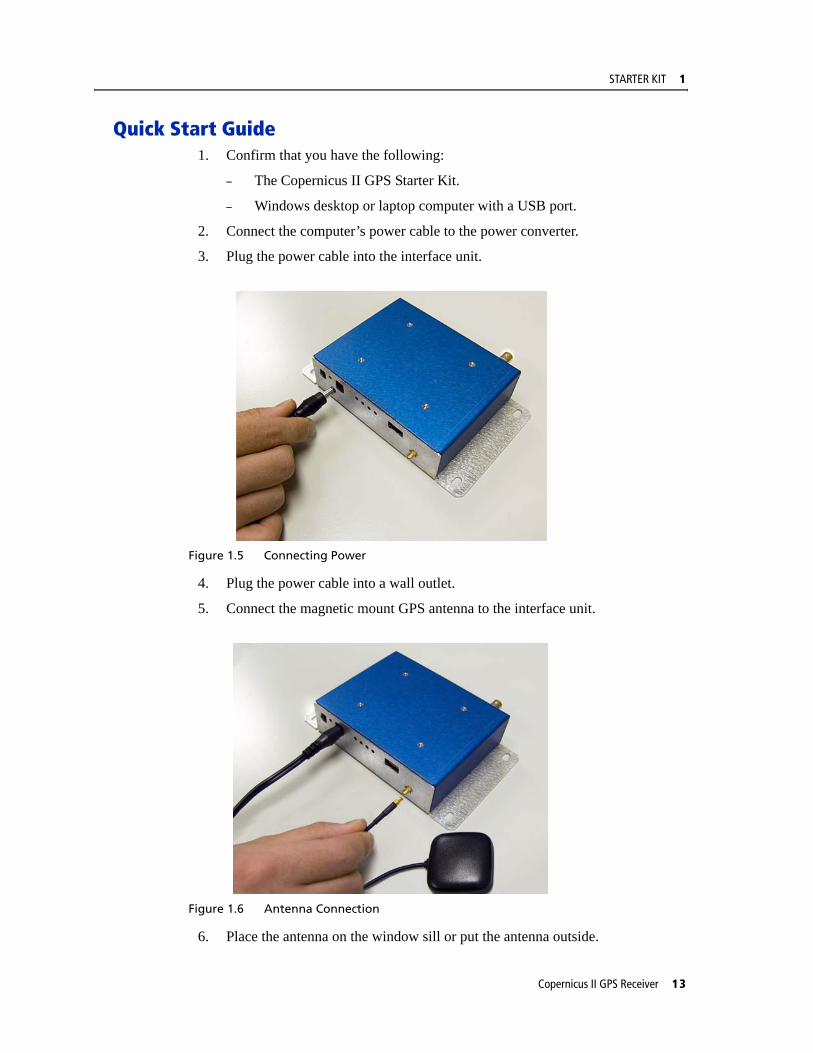
3. Plug the power cable into the interface unit.
Figure 1.5 Connecting Power
4. Plug the power cable into a wall outlet.
5. Connect the magnetic mount GPS antenna to the interface unit.
Figure 1.6 Antenna Connection
6. Place the antenna on the window sill or put the antenna outside.
Copernicus II GPS Receiver 13

1 STARTER KIT
7. Connect the USB cable to the USB connector on the interface unit.
Figure 1.7 Connecting the PC
8. Power-on your computer.
9. Download and install the appropriate FTDI driver on your PC (see Installing the FTDI USB/Serial Driver Software., page 15).
10. Download and unzip the file containing the Trimble GPS Studio software from the Trimble Copernicus support web page: http://www.trimble.com/embeddedsystems/copernicus.aspx?dtID=support
11. Execute the Trimble GPS Studio.
12. Select one of the USB virtual COM ports. Either the TSIP or NMEA data stream is visible on your monitor. To view the other protocol, select a different USB virtual COM port.
14 Copernicus II GPS Receiver
STARTER KIT 1
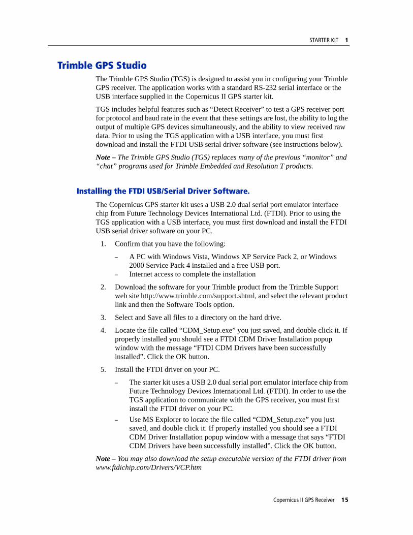
Trimble GPS StudioThe Trimble GPS Studio (TGS) is designed to assist you in configuring your Trimble GPS receiver. The application works with a standard RS-232 serial interface or the USB interface supplied in the Copernicus II GPS starter kit.
TGS includes helpful features such as “Detect Receiver” to test a GPS receiver port for protocol and baud rate in the event that these settings are lost, the ability to log the output of multiple GPS devices simultaneously, and the ability to view received raw data. Prior to using the TGS application with a USB interface, you must first download and install the FTDI USB serial driver software (see instructions below).
Note – The Trimble GPS Studio (TGS) replaces many of the previous “monitor” and “chat” programs used for Trimble Embedded and Resolution T products.
Installing the FTDI USB/Serial Driver Software.
The Copernicus GPS starter kit uses a USB 2.0 dual serial port emulator interface chip from Future Technology Devices International Ltd. (FTDI). Prior to using the TGS application with a USB interface, you must first download and install the FTDI USB serial driver software on your PC.
1. Confirm that you have the following:
– A PC with Windows Vista, Windows XP Service Pack 2, or Windows 2000 Service Pack 4 installed and a free USB port.
– Internet access to complete the installation
2. Download the software for your Trimble product from the Trimble Support web site http://www.trimble.com/support.shtml, and select the relevant product link and then the Software Tools option.
3. Select and Save all files to a directory on the hard drive.
4. Locate the file called “CDM_Setup.exe” you just saved, and double click it. If properly installed you should see a FTDI CDM Driver Installation popup window with the message “FTDI CDM Drivers have been successfully installed”. Click the OK button.
5. Install the FTDI driver on your PC.
– The starter kit uses a USB 2.0 dual serial port emulator interface chip from Future Technology Devices International Ltd. (FTDI). In order to use the TGS application to communicate with the GPS receiver, you must first install the FTDI driver on your PC.
– Use MS Explorer to locate the file called “CDM_Setup.exe” you just saved, and double click it. If properly installed you should see a FTDI CDM Driver Installation popup window with a message that says “FTDI CDM Drivers have been successfully installed”. Click the OK button.
Note – You may also download the setup executable version of the FTDI driver from www.ftdichip.com/Drivers/VCP.htm
Copernicus II GPS Receiver 15

1 STARTER KIT
Connect the PC via the USB serial interface.
1. Right-click the MyComputer icon.
2. Select the Properties option to view the System Properties Window.
3. Select the Hardware tab.
4. Click the Device Manager button.
16 Copernicus II GPS Receiver
STARTER KIT 1
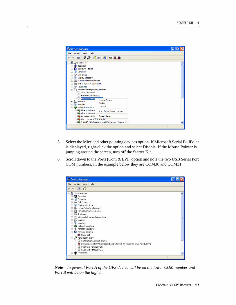
5. Select the Mice and other pointing devices option. If Microsoft Serial BallPoint is displayed, right-click the option and select Disable. If the Mouse Pointer is jumping around the screen, turn off the Starter Kit.
6. Scroll down to the Ports (Com & LPT) option and note the two USB Serial Port COM numbers. In the example below they are COM30 and COM31.
Note – In general Port A of the GPS device will be on the lower COM number and Port B will be on the higher.
Copernicus II GPS Receiver 17
1 STARTER KIT
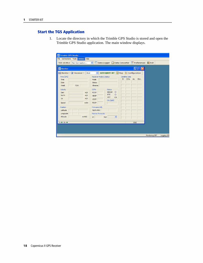
Start the TGS Application
1. Locate the directory in which the Trimble GPS Studio is stored and open the Trimble GPS Studio application. The main window displays.
18 Copernicus II GPS Receiver

STARTER KIT 1
Connect to the GPS Receiver
1. Select Connections > Auto Detect.The GPS receiver is connected.
2. Select the port and protocol being used on the module.
Note – If you do not know which protocol is being used, select TSIP, TAIP and NMEA. The TGS will try each in turn at different baud rates.
Copernicus II GPS Receiver 19

1 STARTER KIT
3. Click the Yes button to accept the connection parameters.
Configure the GPS Ports
1. Select the Receiver > Configure.
20 Copernicus II GPS Receiver

STARTER KIT 1
2. Select the Port Configuration tab.
3. Select the required receiver port, baud rate, parity, data bits and stop bits.
4. Select one input and one output protocol.
5. Click the Set button.
6. To permanently save this configuration, click the Save Configuration button.
Copernicus II GPS Receiver 21

1 STARTER KIT
Configure the Output Formats
1. Select the Receiver > Configure.
2. Select the Outputs tab.
3. Select the required setup options.
4. Click the Set button.
5. To permanently save this configuration, click the Save Configuration button.
22 Copernicus II GPS Receiver
STARTER KIT 1
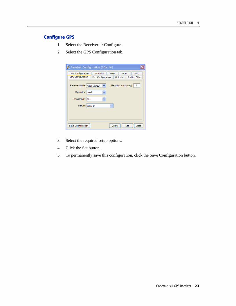
Configure GPS
1. Select the Receiver > Configure.
2. Select the GPS Configuration tab.
3. Select the required setup options.
4. Click the Set button.
5. To permanently save this configuration, click the Save Configuration button.
Copernicus II GPS Receiver 23
1 STARTER KIT
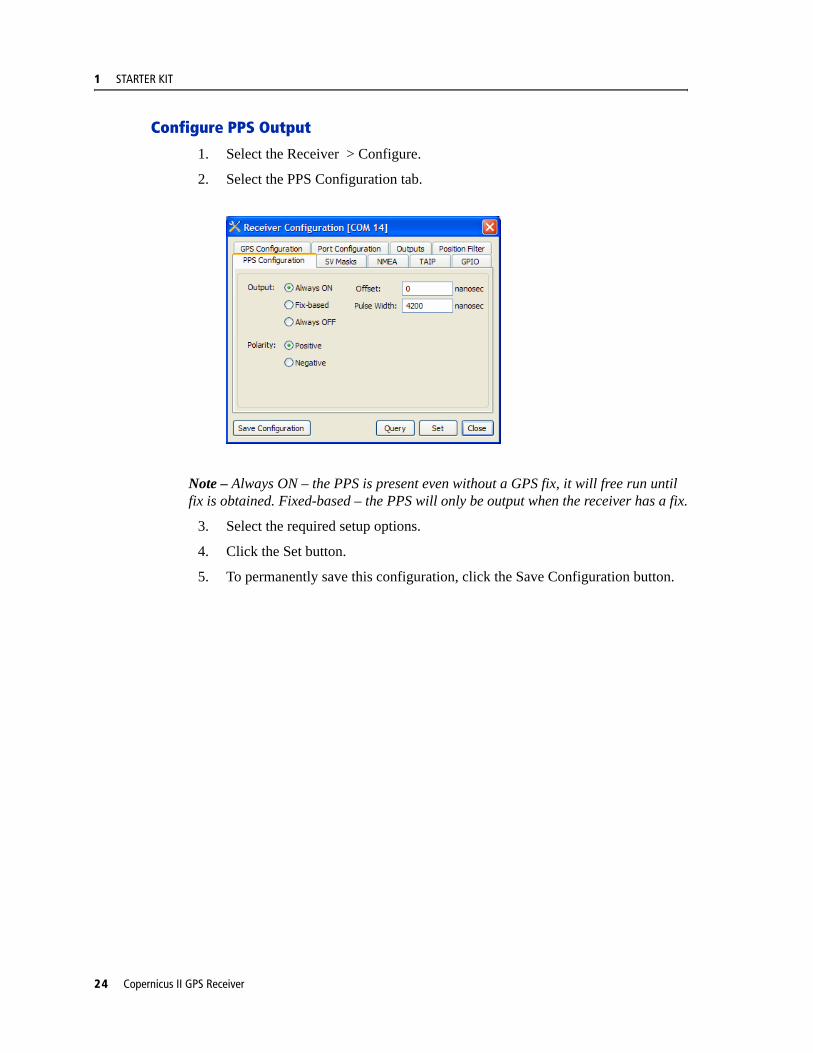
Configure PPS Output
1. Select the Receiver > Configure.
2. Select the PPS Configuration tab.
Note – Always ON – the PPS is present even without a GPS fix, it will free run until fix is obtained. Fixed-based – the PPS will only be output when the receiver has a fix.
3. Select the required setup options.
4. Click the Set button.
5. To permanently save this configuration, click the Save Configuration button.
24 Copernicus II GPS Receiver
STARTER KIT 1
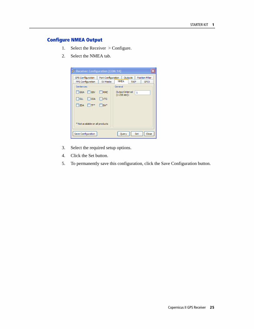
Configure NMEA Output
1. Select the Receiver > Configure.
2. Select the NMEA tab.
3. Select the required setup options.
4. Click the Set button.
5. To permanently save this configuration, click the Save Configuration button.
Copernicus II GPS Receiver 25
1 STARTER KIT
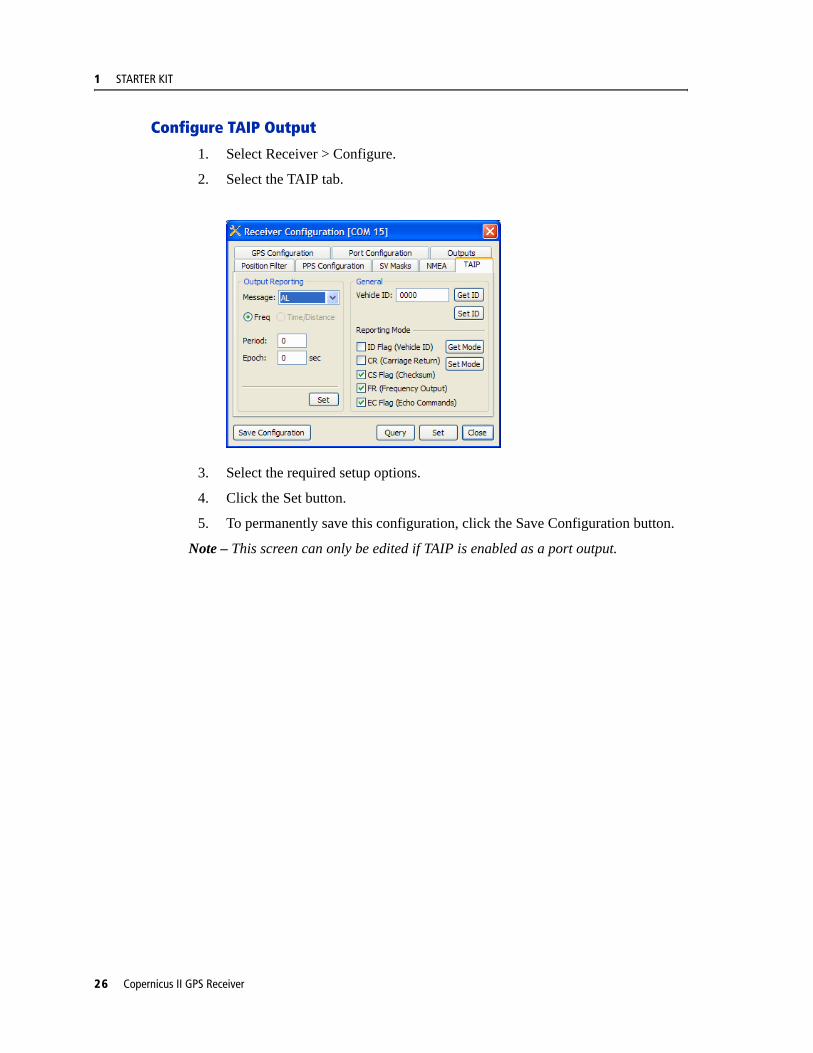
Configure TAIP Output
1. Select Receiver > Configure.
2. Select the TAIP tab.
3. Select the required setup options.
4. Click the Set button.
5. To permanently save this configuration, click the Save Configuration button.
Note – This screen can only be edited if TAIP is enabled as a port output.
26 Copernicus II GPS Receiver

STARTER KIT 1
Create a Log
Follow these steps to log the output of the GPS Receiver.
1. Select Data Logger.
2. From the available ports select the COM port that connects to your device.
3. Create a filename and path in the file field.
4. Use standard file naming if appropriate with the Unit ID and Test Case number
5. Select the correct protocol and logging options.
6. Select Start Logging.
Copernicus II GPS Receiver 27
1 STARTER KIT
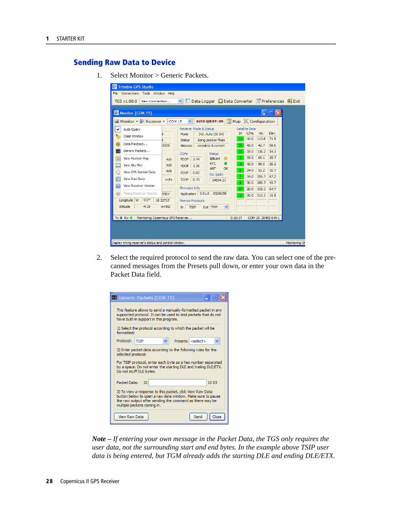
Sending Raw Data to Device
1. Select Monitor > Generic Packets.
2. Select the required protocol to send the raw data. You can select one of the pre-canned messages from the Presets pull down, or enter your own data in the Packet Data field.
Note – If entering your own message in the Packet Data, the TGS only requires the user data, not the surrounding start and end bytes. In the example above TSIP user data is being entered, but TGM already adds the starting DLE and ending DLE/ETX.
28 Copernicus II GPS Receiver
STARTER KIT 1
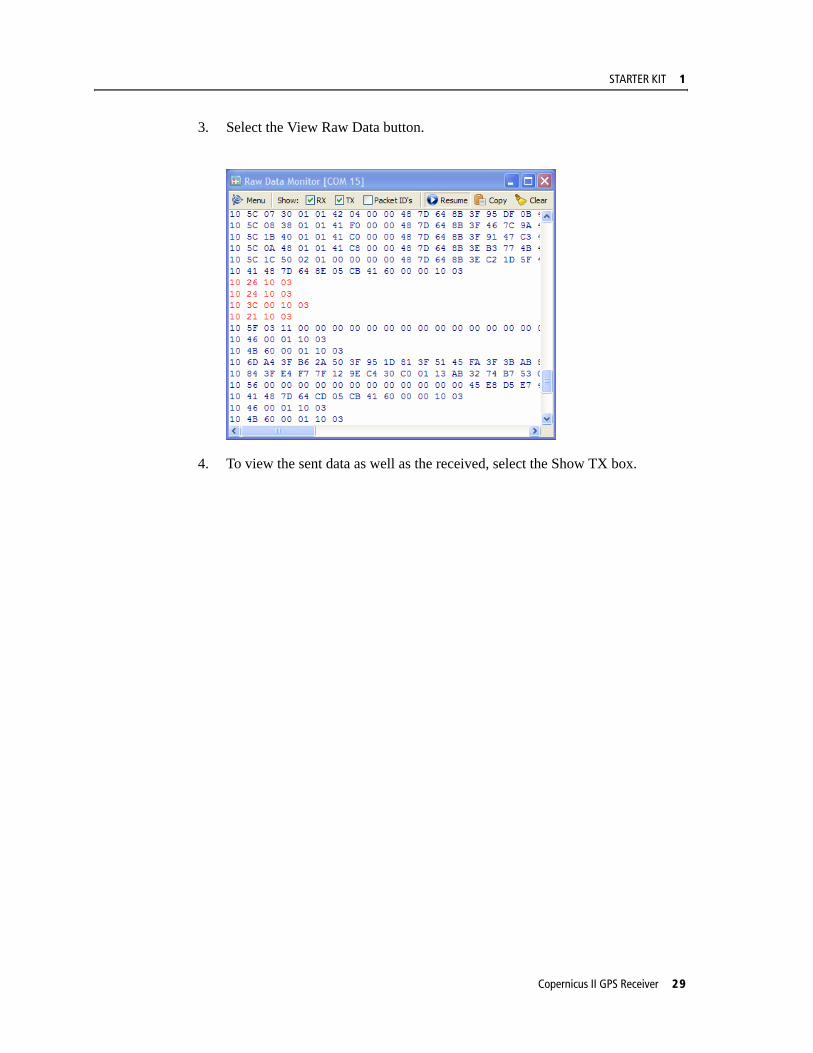
3. Select the View Raw Data button.
4. To view the sent data as well as the received, select the Show TX box.
Copernicus II GPS Receiver 29
1 STARTER KIT
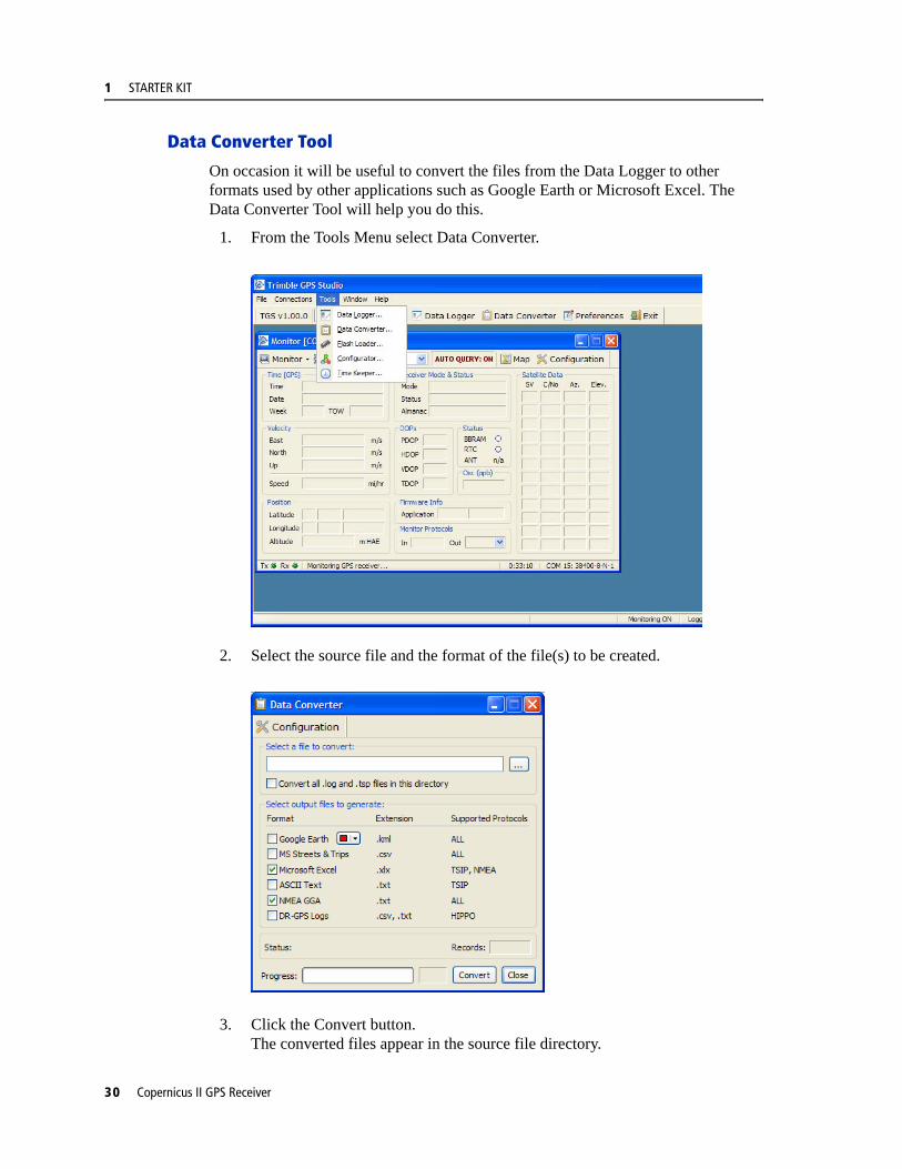
Data Converter Tool
On occasion it will be useful to convert the files from the Data Logger to other formats used by other applications such as Google Earth or Microsoft Excel. The Data Converter Tool will help you do this.
1. From the Tools Menu select Data Converter.
2. Select the source file and the format of the file(s) to be created.
3. Click the Convert button.The converted files appear in the source file directory.
30 Copernicus II GPS Receiver

STARTER KIT 1
Copernicus II GPS Receiver 31

1 STARTER KIT
32 Copernicus II GPS Receiver

C H A P T E R
2
PRODUCT DESCRIPTION 2In this chapter:
Key Features
Specifications
Interface
Absolute Minimum and Maximum Limits
Normal Operating Conditions
Power Consumption Over Temperature and Voltage
ESD Protection
Ordering Information
This chapter describes the Copernicus II GPS receiver features and performance specifications.
Copernicus II GPS Receiver 35
2 PRODUCT DESCRIPTION
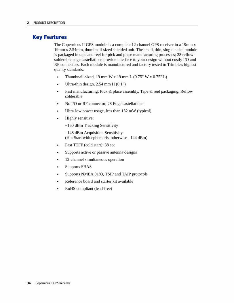
Key FeaturesThe Copernicus II GPS module is a complete 12-channel GPS receiver in a 19mm x 19mm x 2.54mm, thumbnail-sized shielded unit. The small, thin, single-sided module is packaged in tape and reel for pick and place manufacturing processes; 28 reflow-solderable edge castellations provide interface to your design without costly I/O and RF connectors. Each module is manufactured and factory tested to Trimble's highest quality standards.
• Thumbnail-sized, 19 mm W x 19 mm L (0.75" W x 0.75" L)
• Ultra-thin design, 2.54 mm H (0.1")
• Fast manufacturing: Pick & place assembly, Tape & reel packaging, Reflow solderable
• No I/O or RF connector; 28 Edge castellations
• Ultra-low power usage, less than 132 mW (typical)
• Highly sensitive:
−160 dBm Tracking Sensitivity
−148 dBm Acquisition Sensitivity (Hot Start with ephemeris, otherwise −144 dBm)
• Fast TTFF (cold start): 38 sec
• Supports active or passive antenna designs
• 12-channel simultaneous operation
• Supports SBAS
• Supports NMEA 0183, TSIP and TAIP protocols
• Reference board and starter kit available
• RoHS compliant (lead-free)
36 Copernicus II GPS Receiver

PRODUCT DESCRIPTION 2
Block Diagram
Figure 2.1 Copernicus II GPS Block Diagram
Copernicus II GPS Receiver 37

2 PRODUCT DESCRIPTION
Specifications
Performance
Performance Specifications
L1 (1575.42 MHz) frequency, C/A code, 12-channel, continuous tracking receiver
Update Rate
TSIP 1 Hz
NMEA 1 Hz
TAIP 1 Hz
Accuracy (24 hour static)
Horizontal (without SBAS) <2.5 m 50%, <5 m 90%
Horizontal (with SBAS) <2.0 m 50%, <4 m 90%
Altitude (without SBAS) <5 m 50%, <8 m 90%
Altitude (with SBAS) <3 m 50%, <5 m 90%
Velocity 0.06 m/sec
PPS (static) ±60 ns RMS
PPS (Stationary Mode “indoor” @ -145dBm)
±350 ns RMS
Acquisition (Autonomous Operation)
Re-acquisition 2 sec
Hot Start 3 sec
Hot Start without battery back-up
8 sec (Ephemeris is not older than 4 hours)
Warm Start 35 sec
Cold Start 38 sec
Out of the Box 41 sec
Sensitivity
Tracking -160 dBm
Acquisition Sensitivity(Standard Sensitivity Mode)
-142 dBm
Acquisition Sensitivity(High Sensitivity Mode)
-148 dBm (Hot Start with ephemeris, otherwise -144 dBm)
Operational
Speed Limit 515 m/s
38 Copernicus II GPS Receiver
PRODUCT DESCRIPTION 2
Interface
Electrical
Physical
Environmental
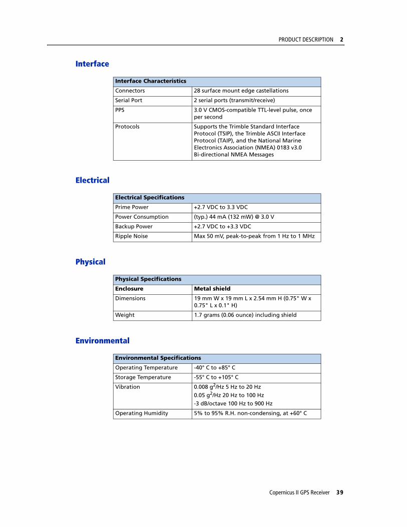
Interface Characteristics
Connectors 28 surface mount edge castellations
Serial Port 2 serial ports (transmit/receive)
PPS 3.0 V CMOS-compatible TTL-level pulse, once per second
Protocols Supports the Trimble Standard Interface Protocol (TSIP), the Trimble ASCII Interface Protocol (TAIP), and the National Marine Electronics Association (NMEA) 0183 v3.0 Bi-directional NMEA Messages
Electrical Specifications
Prime Power +2.7 VDC to 3.3 VDC
Power Consumption (typ.) 44 mA (132 mW) @ 3.0 V
Backup Power +2.7 VDC to +3.3 VDC
Ripple Noise Max 50 mV, peak-to-peak from 1 Hz to 1 MHz
Physical Specifications
Enclosure Metal shield
Dimensions 19 mm W x 19 mm L x 2.54 mm H (0.75" W x 0.75" L x 0.1" H)
Weight 1.7 grams (0.06 ounce) including shield
Environmental Specifications
Operating Temperature -40° C to +85° C
Storage Temperature -55° C to +105° C
Vibration 0.008 g2/Hz 5 Hz to 20 Hz
0.05 g2/Hz 20 Hz to 100 Hz-3 dB/octave 100 Hz to 900 Hz
Operating Humidity 5% to 95% R.H. non-condensing, at +60° C
Copernicus II GPS Receiver 39

2 PRODUCT DESCRIPTION
Absolute Minimum and Maximum LimitsAbsolute maximum ratings indicate conditions beyond which permanent damage to the device may occur. Electrical specifications shall not apply when operating the device outside its rated operating conditions.
Note – See Copernicus II GPS Receiver Standby Current, page 59 for information on the standby current.
Parameter Min Max Unit
Power Supply
Power Supply Voltage (VCC) on Pin 12
-0.3 3.6 V
STANDBY Voltage (Vbat) on Pin 6
-0.3 3.6 V
Antenna
Input Power at RF Input +10 dBm
Input Gain at RF Input 0 (passive antenna)
36 dB
Input / Output Pin Threshold Levels
Input Pin Voltage (RXD-A, RXD-B, Open, Short, Reserved Pins, Xreset, Xstandby)
Status Min Max Unit
High 2.0 3.6 V
Low 0 0.8 V
Output Pin Voltage (TXD-A, TXD-B, LNA_XEN)
Status Min Max Unit
High (loh = 1 mA) 0.8 * VCC VCC V
Low (lol = 1 mA) 0 0.2 * VCC V
40 Copernicus II GPS Receiver
PRODUCT DESCRIPTION 2
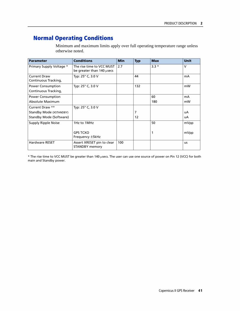
Normal Operating ConditionsMinimum and maximum limits apply over full operating temperature range unless otherwise noted.
* The rise time to VCC MUST be greater than 140 μsecs. The user can use one source of power on Pin 12 (VCC) for both main and Standby power.
Parameter Conditions Min Typ Max Unit
Primary Supply Voltage * The rise time to VCC MUST be greater than 140 μsecs
2.7 3.3 * V
Current Draw Continuous Tracking,
Typ: 25° C, 3.0 V 44 mA
Power ConsumptionContinuous Tracking,
Typ: 25° C, 3.0 V 132 mW
Power ConsumptionAbsolute Maximum
60180
mAmW
Current Draw **Standby Mode (XSTANDBY)
Standby Mode (Software)
Typ: 25° C, 3.0 V712
uAuA
Supply Ripple Noise 1Hz to 1MHz
GPS TCXO Frequency ±5kHz
50
1
mVpp
mVpp
Hardware RESET Assert XRESET pin to clear STANDBY memory
100 us
Copernicus II GPS Receiver 41
2 PRODUCT DESCRIPTION
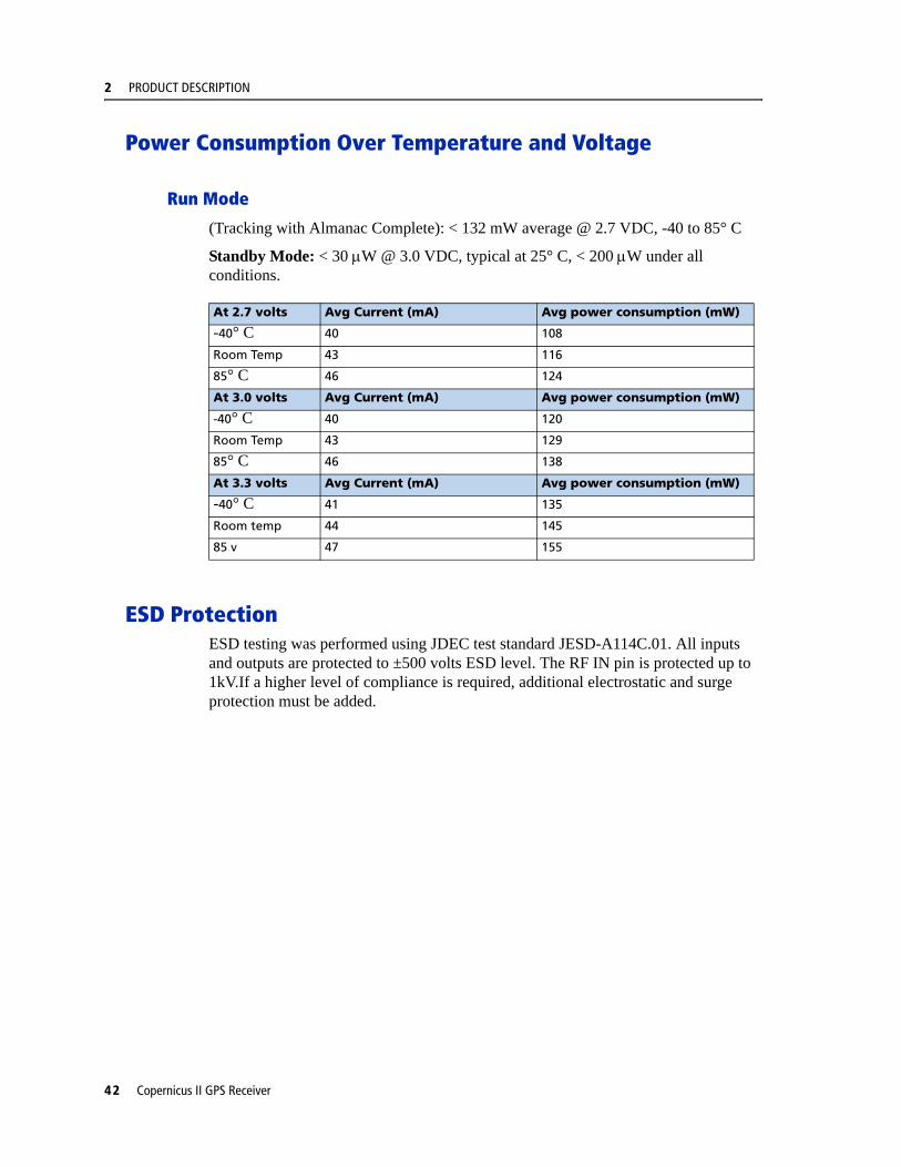
Power Consumption Over Temperature and Voltage
Run Mode
(Tracking with Almanac Complete): < 132 mW average @ 2.7 VDC, -40 to 85° C
Standby Mode: < 30 μW @ 3.0 VDC, typical at 25° C, < 200 μW under all conditions.
ESD ProtectionESD testing was performed using JDEC test standard JESD-A114C.01. All inputs and outputs are protected to ±500 volts ESD level. The RF IN pin is protected up to 1kV.If a higher level of compliance is required, additional electrostatic and surge protection must be added.
At 2.7 volts Avg Current (mA) Avg power consumption (mW)
-40° C 40 108
Room Temp 43 116
85° C 46 124
At 3.0 volts Avg Current (mA) Avg power consumption (mW)
-40° C 40 120
Room Temp 43 129
85° C 46 138
At 3.3 volts Avg Current (mA) Avg power consumption (mW)
-40° C 41 135
Room temp 44 145
85 v 47 155
42 Copernicus II GPS Receiver
PRODUCT DESCRIPTION 2
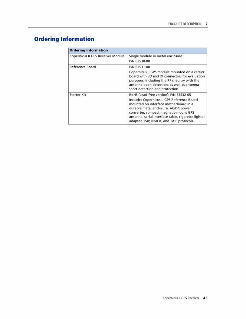
Ordering Information
Ordering Information
Copernicus II GPS Receiver Module Single module in metal enclosure
P/N 63530-00
Reference Board P/N 63531-00
Copernicus II GPS module mounted on a carrier board with I/O and RF connectors for evaluation purposes, including the RF circuitry with the antenna open detection, as well as antenna short detection and protection.
Starter Kit RoHS (Lead-free version): P/N 63532-05
Includes Copernicus II GPS Reference Board mounted on interface motherboard in a durable metal enclosure, AC/DC power converter, compact magnetic-mount GPS antenna, serial interface cable, cigarette lighter adapter, TSIP, NMEA, and TAIP protocols.
Copernicus II GPS Receiver 43

2 PRODUCT DESCRIPTION
44 Copernicus II GPS Receiver

C H A P T E R
3
INTERFACE CHARACTERISTICS 3In this chapter:
Pin Assignments
Pin Description
Serial Port Default Settings
GPS Timing
A-GPS
Pulse-Per-Second (PPS)
This chapter provides a detailed description of the Copernicus II GPS Receiver interface.
Copernicus II GPS Receiver 45

3 INTERFACE CHARACTERISTICS
Pin Assignments
Figure 3.1 Copernicus II GPS Receiver Pin Assignments
46 Copernicus II GPS Receiver

INTERFACE CHARACTERISTICS 3
Pin DescriptionTable 3.1 Pin Description
G: Ground; I: Input; O: Output; P: Power
Pin Name Description Function Note1 GND Ground G Signal ground. Connect to common ground.
2 GND RF Ground G One of two RF grounds adjacent to RF input. Connect to RF ground system.
3 RF Input GPS RF input I 50-ohm unbalanced (coaxial) RF input.
4 GND RF Ground G One of two RF grounds adjacent to RF input. Connect to RF ground system.
5 LNA_XEN LNA Enable O Can be used with active antennas only. Active low logic level signal to control external LNA.
6 Vbat Battery Backup P Voltage supply for backup battery 2.7 - 3.3V
7 OPEN Antenna OPEN I Logic level from external antenna detection circuit. See “Antenna Detect Truth Table”.
8 SHORT Antenna SHORT I/O Logic level from external antenna detection circuit. See “Antenna Detect Truth Table”.
9 Reserved Reserved I Do not connect
10 Reserved Reserved I Do not connect
11 XRESET Reset I Active low logic level reset. Do not connect if not used.
12 VCC Supply voltage P Module power supply 2.7 - 3.3 VDC
13 GND Ground G Signal ground. Connect to common ground.
14 GND Ground G Signal ground. Connect to common ground.
15 GND Ground G Signal ground. Connect to common ground.
16 XSTANDBY Run/Standby I Selects “RUN” or “STANDBY” mode. Connect to VCC if not used (run only).
17 Reserved Reserved I/O Do not connect.
18 Reserved Reserved I/O Do not connect.
19 PPS Pulse per second O Logic level timing signal at 1 Hz. Do not connect if not used.
20 RXD_B Serial port B receive I Logic level secondary serial port receive.
21 RXD_A Serial port A receive I Logic level primary serial port receive.
22 Reserved Reserved I/O Do not connect.
23 TXD_A Serial port A transmit O Logic level primary serial port transmit.
24 TXD_B Serial port B transmit O Logic level secondary serial port transmit.
25 Reserved Reserved I/O Do not connect.
26 Reserved Reserved I/O Do not connect.
27 GND Ground G Signal ground. Connect to common ground.
28 GND Ground G Signal ground. Connect to common ground.
Copernicus II GPS Receiver 47
3 INTERFACE CHARACTERISTICS
Detailed Pin Descriptions
RF Input
The RF input pin is the 50 ohm unbalanced GPS RF input, and can be used with active or passive antennas.
Passive antennas: The RF input pin may be connected by a low-loss 50 ohm unbalanced transmission system to the passive GPS antenna if loss is minimal (< 2 dB). It is recommend that you use an external LNA with a passive antenna.
Active Antennas: The RF input pin can also be connected to the output of an external low-noise amplifier, which is amplifying GPS signals from the antenna. The gain of the LNA must be great enough to overcome transmission losses from the LNA output to this pin. The specification for noise figure for the module is < 3 dB at room temperature and < 4 dB over the specified temperature range, -40 to +85 C. The external LNA must be located such that the loss from the GPS antenna connection to the LNA input is minimized, preferably < 1 dB. The noise figure of the LNA should be as low as possible, preferably< 2 dB. This specification is provided to enable a cascaded noise figure design calculation. Active antennas must be powered with a single bias-Tee circuit.
LNA_XEN
This logic level output can be used to control power to an external LNA or other circuitry. The logic of this signal is such that when the module is running (not in standby), this signal is low. During “STANDBY” mode, this signal is high. This pin may be used to control the gate of a p-channel FET used as a switch.
Open/Short Pins
When using an active antenna, it is recommended that you implement an antenna detection circuit with short circuit protection. There are two pins provided for reporting the antenna status: OPEN and SHORT.
The logic level inputs outlined in Table 3.2 may be used with a detection circuit (with or without protection) to monitor the status of the external LNA of an active antenna by the module.
The truth table for the logic of these signals is provided in Table 3.2. These input pins conform to the Input / Output Pin threshold levels specified in.
A typical active antenna draws between 10 to 20mA.The antenna Protect/Detect circuit will trip as a short circuit at around 100mA. It is best to keep the antenna current below 75mA. An open circuit will be determined if the antenna current falls below approximately 2mA.
48 Copernicus II GPS Receiver
INTERFACE CHARACTERISTICS 3
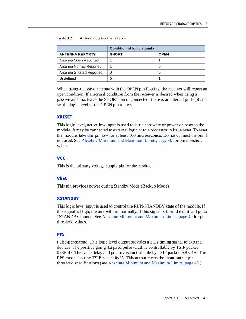
Table 3.2 Antenna Status Truth Table
When using a passive antenna with the OPEN pin floating, the receiver will report an open condition. If a normal condition from the receiver is desired when using a passive antenna, leave the SHORT pin unconnected (there is an internal pull-up) and set the logic level of the OPEN pin to low.
XRESET
This logic-level, active low input is used to issue hardware or power-on reset to the module. It may be connected to external logic or to a processor to issue reset. To reset the module, take this pin low for at least 100 microseconds. Do not connect the pin if not used. See Absolute Minimum and Maximum Limits, page 40 for pin threshold values.
VCC
This is the primary voltage supply pin for the module.
Vbat
This pin provides power during Standby Mode (Backup Mode).
XSTANDBY
This logic level input is used to control the RUN/STANDBY state of the module. If this signal is High, the unit will run normally. If this signal is Low, the unit will go to “STANDBY” mode. See Absolute Minimum and Maximum Limits, page 40 for pin threshold values.
PPS
Pulse-per-second. This logic level output provides a 1 Hz timing signal to external devices. The positive going 4.2 μsec pulse width is controllable by TSIP packet 0x8E-4F. The cable delay and polarity is controllable by TSIP packet 0x8E-4A. The PPS mode is set by TSIP packet 0x35. This output meets the input/output pin threshold specifications (see Absolute Minimum and Maximum Limits, page 40.)
Condition of logic signalsANTENNA REPORTS SHORT OPENAntenna Open Reported 1 1
Antenna Normal Reported 1 0
Antenna Shorted Reported 0 0
Undefined 0 1
Copernicus II GPS Receiver 49
3 INTERFACE CHARACTERISTICS
RXD_A and RXD_B
These logic level inputs are the primary (A) and secondary (B) serial port receive lines (data input to the module). This output meets the input/output pin threshold specifications (see Absolute Minimum and Maximum Limits, page 40). The baud rate for the two ports is under software control.
TXD_A and TXD_B
These logic level outputs are the primary (A) and secondary (B) serial port transmit lines (data moving away from the module). This output meets the input/output pin threshold specifications (see Absolute Minimum and Maximum Limits, page 40). The baud rate for the two ports is under firmware control.
Reserved Pins
There are 7 reserved pins on the Copernicus II GPS receiver. For the recommended pin connections for these reserved pins, see Table 3.1.
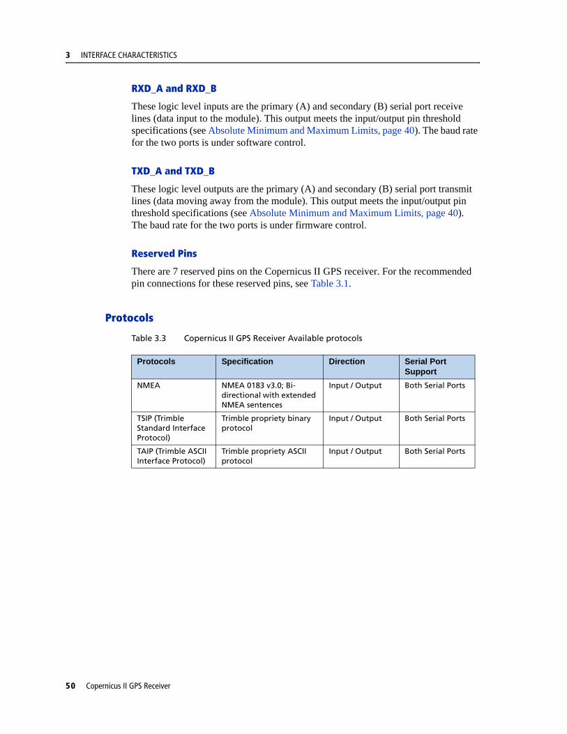
Protocols
Table 3.3 Copernicus II GPS Receiver Available protocols
Protocols Specification Direction Serial Port Support
NMEA NMEA 0183 v3.0; Bi-directional with extended NMEA sentences
Input / Output Both Serial Ports
TSIP (Trimble Standard Interface Protocol)
Trimble propriety binary protocol
Input / Output Both Serial Ports
TAIP (Trimble ASCII Interface Protocol)
Trimble propriety ASCII protocol
Input / Output Both Serial Ports
50 Copernicus II GPS Receiver
INTERFACE CHARACTERISTICS 3
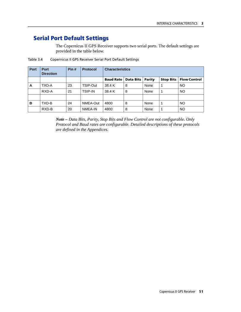
Serial Port Default SettingsThe Copernicus II GPS Receiver supports two serial ports. The default settings are provided in the table below.
Table 3.4 Copernicus II GPS Receiver Serial Port Default Settings
Note – Data Bits, Parity, Stop Bits and Flow Control are not configurable. Only Protocol and Baud rates are configurable. Detailed descriptions of these protocols are defined in the Appendices.
Port Port Direction
Pin # Protocol Characteristics
Baud Rate Data Bits Parity Stop Bits Flow Control
A TXD-A 23 TSIP-Out 38.4 K 8 None 1 NO
RXD-A 21 TSIP-IN 38.4 K 8 None 1 NO
B TXD-B 24 NMEA-Out 4800 8 None 1 NO
RXD-B 20 NMEA-IN 4800 8 None 1 NO
Copernicus II GPS Receiver 51
3 INTERFACE CHARACTERISTICS
GPS TimingIn many timing applications, such as time/frequency standards, site synchronization systems, and event measurement systems, GPS receivers are used to discipline local oscillators.
The GPS constellation consists of 24 orbiting satellites. Each GPS satellite contains a highly-stable atomic (Cesium) clock, which is continuously monitored and corrected by the GPS control segment. Consequently, the GPS constellation can be considered a set of 24 orbiting clocks with worldwide 24-hour coverage.
GPS receivers use the signals from these GPS clocks to correct their internal clock which is not as stable or accurate as the GPS atomic clocks. GPS receivers like the Copernicus II output a highly accurate timing pulse (PPS) generated by an internal clock which is constantly corrected using the GPS clocks. This timing pulse is synchronized to UTC within ±60 ns rms.
In addition to serving as a highly accurate stand-alone time source, GPS receivers are used to synchronize distant clocks in communication or data networks. This synchronization is possible since all GPS satellite clocks are corrected to a common master clock. Therefore, the relative clock error is the same, regardless of which satellite or satellites are used. For timing applications requiring a common clock, GPS is the ideal solution.
Position and time errors are related by the speed of light. Therefore, a position error of 100 meters corresponds to a time error of approximately 333 ns. The hardware and software implementation affects the GPS receiver's PPS accuracy level. The receiver's clocking rate determines the PPS steering resolution.
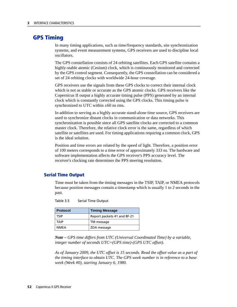
Serial Time Output
Time must be taken from the timing messages in the TSIP, TAIP, or NMEA protocols because position messages contain a timestamp which is usually 1 to 2 seconds in the past.
Table 3.5 Serial Time Output
Note – GPS time differs from UTC (Universal Coordinated Time) by a variable, integer number of seconds UTC=(GPS time)-(GPS UTC offset).
As of January 2009, the UTC offset is 15 seconds. Read the offset value as a part of the timing interface to obtain UTC. The GPS week number is in reference to a base week (Week #0), starting January 6, 1980.
Protocol Timing MessageTSIP Report packets 41 and 8F-21
TAIP TM message
NMEA ZDA message
52 Copernicus II GPS Receiver

INTERFACE CHARACTERISTICS 3
Acquiring the Correct Time
To acquire the correct time:
1. Confirm that the almanac is complete and the receiver is generating 3D fixes. This will eliminate the UTC offset jump.
2. Confirm that the receiver is configured for the late PPS option (i.e., it is only outputting a PPS on a 3D fix).
3. Capture the time from TSIP packet 0x41 or TSIP packet 0x8F-20 (if using TSIP).
4. Once time is acquired, on the next PPS add 1 to the whole second to read the correct time.
Note – The minimum time resolution is 1 second.
Copernicus II GPS Receiver 53

3 INTERFACE CHARACTERISTICS
A-GPSThe Copernicus II GPS Receiver is equipped with assisted GPS (A-GPS), which enables the receiver to obtain a position fix within seconds using almanac, ephemeris, time, and position data. This position data can be uploaded to the device via TSIP packets or the Trimble GPS Studio (TGS) application. When A-GPS is enabled, the Copernicus II GPS Receiver can achieve fast start-up times characteristic of a hot start.
Follow the procedures below to download current almanac, ephemeris, time, and position information, and then upload this data to the starter kit module via TGS or TSIP (to upload position data within the customer application).
C Warning – To ensure proper format of the ephemeris file and almanac file, a Trimble receiver must be used to gather this data. Almanac files from non-Trimble receivers may not be in proper format and thus may not work, (i.e. almanac files downloaded from the Internet).
Enabling A-GPS with the Trimble GPS Studio Application (TGS)
1. Attach the Copernicus II interface unit to your PC.
2. Place the GPS antenna where there is a clear view of sky.
3. Allow the starter kit to run and calculate fixes.
4. On the main screen, wait for the almanac indicator to turn green confirming that the receiver has collected a current almanac.
Note – It takes 12,5 minutes of uninterrupted Copernicus II operation to collect almanac from the satellites.
5. Click on the initialized pull-down menu and use the download features on the bottom of the pull-down to download the almanac, position, time and ephemeris files on your PC.
6. Now that you have collected these files, you can upload them using the upload features on the initialize pull-down window in TGS.
Note – The collected ephemeris is only good for approximately 2 hours.
54 Copernicus II GPS Receiver
INTERFACE CHARACTERISTICS 3
Enabling A-GPS with TSIP
1. Allow the receiver to run long enough to collect a current almanac.
Note – It takes 12,5 minutes of uninterrupted Copernicus II operation to collect almanac from the satellites.
2. Use packet 0 x 26 to request the health of the receiver. The response packets 0x46 and 0x4B indicate when the almanac is complete and current.
3. Use packet 0x38 to request the almanac and the ephemeris. The receiver responds with packet 0 x 58.
4. Use packet 0 x 21 to request time from the receiver. The receiver responds with packet 0x 41. This data can be used to set your own off-board clock.
5. Use packets 0x42, 0x4A, 0x83 0r 0x84 to request a position from the receiver.
To upload this information back to the receiver, follow this procedures in the specified order:
1. Upload the time using TSIP packet 0x2E. Wait for upload confirmation report packet 0x41.
2. Upload position using TSIP packet 0x31 or 0x32. No confirmation report packet available.
3. Upload the ephemeris using TSIP packet 0x38. Wait for the upload confirmation report TSIP packet 0x58.
Note – See Appendix A for details on the TSIP protocol.
Copernicus II GPS Receiver 55

3 INTERFACE CHARACTERISTICS
Pulse-Per-Second (PPS)The Copernicus II GPS receiver provides a CMOS compatible TTL level Pulse-Per-Second (PPS). The PPS is a positive pulse available on pin 19 of the Copernicus II GPS Receiver. The rising edge of the PPS pulse is synchronized with respect to UTC. The timing accuracy is ±60 ns when valid position fixes are being reported.
The precise UTC or GPS time is reported in TSIP message 0x41 and NMEA message EDA. The line reports are sent within 500ms after the corresponding PPS.
The rising edge of the pulse is typically less than 6 nanoseconds. The distributed impedance of the attached signal line and input circuit can affect the pulse shape and rise time. The PPS can drive a load up to 1mA without damaging the module. The falling edge of the pulse should not be used.
The Copernicus II default PPS output mode is Always On, sometimes called or “Early PPS”. In Always On mode, PPS is output immediately after main power is applied. The PPS is driven by the Real Time Clock (RTC) until the receiver acquires GPS time from the satellite and begins outputting fixes. In Always On mode, the PPS continues even if the receiver loses GPS lock. The drift of the PPS, when the Copernicus II GPS receiver is not tracking satellites, is unspecified and should not be used for synchronization.
The PPS output modes can be controlled with TSIP packet 0x35 and NMEA “PS” Packet. The modes are Always On (default), Fix Based, or Always Off. Cable delay compensation is available through the use of TSIP packet 0x8E-4A and NMEA “PS” Packet. PPS pulse width is controlled by TSIP packet 0x8E-4F and the NMEA “PS” Packet.
After a specific mode is selected, it can be stored in non-volatile memory (FLASH) using TSIP command 0x8E-26.
Note – PPS can be configured as positive or negative polarity; factory default is positive. The PPS pulse width is also configurable; factory default is 4.2 microseconds.
Stationary Mode
In addition to the LAND, SEA, AIR Dynamics Mode, the Copernicus II can operate in Stationary Mode to produce an accurate and stable PPS using an indoor antenna. In this mode, the receiver conducts a self-survey for a period of about 10 minutes with a clear view or longer with an obstructed view. When the self-survey is complete, the device outputs PPS while tracking one or more satellites.
Features include:
• TRAIM on clock and frequency
• Noise filter to reduce PPS variance
Note – Use TSIP Command 0xBB or NMEA Command CR to set Stationary Mode. When the receiver is in Stationary Mode, the dimension type in TSIP packet 0x6D and in the NMEA GSA messages will be 2D.
56 Copernicus II GPS Receiver
C H A P T E R
4
OPERATING MODES 4In this chapter:
Copernicus II GPS Receiver Operating Modes
Run Mode
Standby Mode
Monitor Mode
Changing the Run/Standby Modes
Saving Almanac, Ephemeris and Position to Flash Memory
WAAS
GPS Receiver Acquisition Sensitivity Mode
This chapter describes the primary Copernicus II GPS Receiver operating modes and provides guidelines for receiver operation.
Copernicus II GPS Receiver 57

4 OPERATING MODES
Copernicus II GPS Receiver Operating ModesTable 4.1 Copernicus II GPS Receiver Operating Modes
Run Mode
The RUN mode is the continuous tracking or the normal mode.
Standby Mode
The Copernicus II GPS Receiver provides a Standby Mode in which the module's RAM memory is kept alive and the real-time clock is running while the rest of the receiver is turned off. RAM memory is used to store the GPS almanac, ephemeris, and last position.
Using this information, together with the time information provided by the real-time clock, the receiver normally provides faster startup times. The type of start-up after Standby Mode depends on the state of the receiver prior to entering Standby Mode and on the length of time the receiver spent in the Standby Mode.
If the receiver has almanac, ephemeris, and position information before entering Standby Mode, and the time spent in Standby Mode is less than two hours, the receiver will typically perform a hot start.
If the receiver has all of the information listed above, but the time spent in Standby Mode is more than two hours, the receiver will typically perform a warm start.
The GPS almanac, ephemeris and recent position are automatically stored in non-volatile Flash memory. Even without time, the receiver can use the information stored in Flash memory to shorten the start-up time. In all cases, the receiver will use all of the available information to do the fastest start-up possible.
Note – In Standby Mode, the power consumption of the unit is very low. See Copernicus II GPS Receiver Standby Current, page 59.
Monitor Mode
Monitor Mode is the operating mode for upgrading the firmware stored in the Flash memory. See Chapter 11 for the firmware upgrade procedure.
Operating Modes DescriptionRun Mode Continuous tracking or
normal mode
Standby Mode Backup power or low power mode
Monitor Mode Flash upgrading mode
58 Copernicus II GPS Receiver
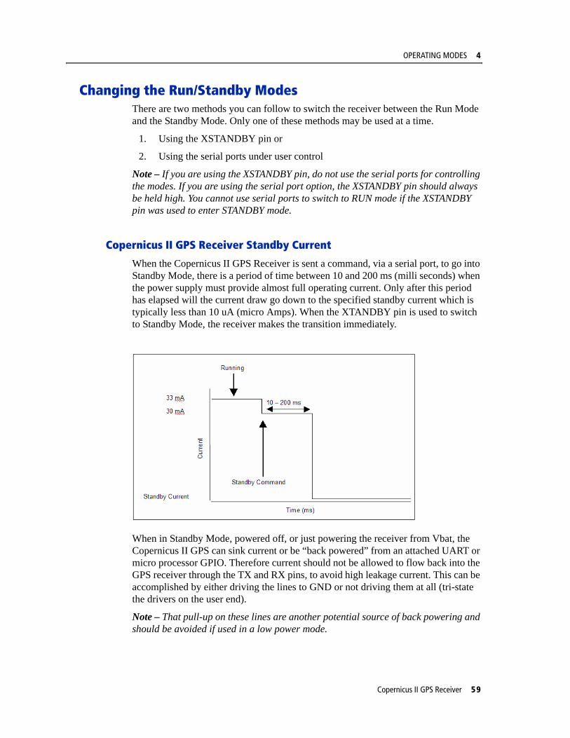
OPERATING MODES 4
Changing the Run/Standby ModesThere are two methods you can follow to switch the receiver between the Run Mode and the Standby Mode. Only one of these methods may be used at a time.
1. Using the XSTANDBY pin or
2. Using the serial ports under user control
Note – If you are using the XSTANDBY pin, do not use the serial ports for controlling the modes. If you are using the serial port option, the XSTANDBY pin should always be held high. You cannot use serial ports to switch to RUN mode if the XSTANDBY pin was used to enter STANDBY mode.
Copernicus II GPS Receiver Standby Current
When the Copernicus II GPS Receiver is sent a command, via a serial port, to go into Standby Mode, there is a period of time between 10 and 200 ms (milli seconds) when the power supply must provide almost full operating current. Only after this period has elapsed will the current draw go down to the specified standby current which is typically less than 10 uA (micro Amps). When the XTANDBY pin is used to switch to Standby Mode, the receiver makes the transition immediately.
When in Standby Mode, powered off, or just powering the receiver from Vbat, the Copernicus II GPS can sink current or be “back powered” from an attached UART or micro processor GPIO. Therefore current should not be allowed to flow back into the GPS receiver through the TX and RX pins, to avoid high leakage current. This can be accomplished by either driving the lines to GND or not driving them at all (tri-state the drivers on the user end).
Note – That pull-up on these lines are another potential source of back powering and should be avoided if used in a low power mode.
Copernicus II GPS Receiver 59

4 OPERATING MODES
Using the XSTANDBY Pin to Switch Modes
The first method for putting the receiver into Standby Mode or exiting this mode back to the Run Mode is through the pin XSTANDBY, pin #16. As long as the pin is held high, the receiver will operate normally in Run Mode.
Entering Standby Mode
When the pin is taken low, the receiver will go to the STANDBY mode.
Exiting Standby Mode
When the pin is taken high again, the receiver will perform a hot or warm restart and return to normal operation. The receiver will hot start if the ephemeris is still valid.
Note – Excessive noise on the XSTANDBY pin could trigger the receiver to reset.
Using Serial Ports to Switch Modes
The second method for putting the receiver into Standby Mode is with TSIP packet 0xC0 or NMEA packet RT.
There are two possible conditions that would trigger the receiver to exit Standby Mode and reset to normal operations:
1. Serial port activity
2. Exit after X elapsed seconds
60 Copernicus II GPS Receiver

OPERATING MODES 4
Serial Port Activity
When the receiver enters Standby Mode through the software protocol commands, the first condition for exiting Standby Mode is using serial port A activity or serial port B activity. The condition is identical for both ports A and B.
To ensure the receiver detects and responds to serial port activity, issue a NULL character on the selected serial port to bring the unit out of Standby Mode. In Standby Mode, the receiver samples for serial port activity at a rate of 32.768 kHz. A NULL character will bring the selected RX line low for 9 bits so even at the highest baud rate of 115200, a NULL character should be detectable at the sample rate.
The Copernicus II GPS receiver may not detect serial port activity during the 3 seconds immediately after receiving a software command to enter Standby Mode. During that 3 seconds, the unit is processing the shut-down command and will ignore serial port activity. Therefore the minimum time between issuing the shut-down command and the use of serial port activity to return the unit to Run Mode is 3 seconds. Standby time cannot be less than 3 seconds.
Exit after X elapsed seconds.
The second condition that will trigger the receiver to exit Standby Mode is the elapse of a pre-defined time. When the receiver is placed into the Standby Mode using protocol commands, the receiver can be made to exit the Standby Mode after a defined elapsed time using TSIP command Packet 0xC0 or NMEA packet RT. In this case, the user specifies the number of seconds the receiver should stay in Standby Mode. After this time has elapsed, the unit will perform a reset and start operating normally.
Note – These conditions are provided to the receiver in the serial command packet, and the user can specify any combination of these conditions as desired. For exiting the Standby Mode, either of the 2 methods can be applied. The first one that occurs will bring the receiver to the RUN Mode to start normal operations.
Copernicus II GPS Receiver 61
4 OPERATING MODES
Saving Almanac, Ephemeris and Position to Flash MemoryThe Almanac, Ephemeris, and recent Position data contained in RAM is automatically saved to Flash memory.
Graceful Shutdown
The Graceful Shutdown command is issued using TSIP packet 0xC0 or NMEA command RT with the store RAM to flash flag enabled. The reset type will depend on the Graceful Shutdown command parameters. On start-up, the unit will use the almanac, ephemeris, and position from RAM first. If RAM is not available, the unit will use the almanac from the Flash Memory.
SBASThe Satellite Based Augmentation System (SBAS) includes implementation of the current standard for WAAS and the European Geostationary Navigation Overlay Service (EGNOS) operated by the European Space Agency and other compatible systems that will come online in the future.
WAASWide Area Augmentation System (WAAS) is an extremely accurate navigation system developed for civil aviation by the Federal Aviation Administration (FAA). The system augments GPS to provide the additional accuracy, integrity, and availability necessary to enable users to rely on GPS for all phases of flight for all qualified airports within the WAAS coverage area.
The worst-case accuracy is within 7.6 meters of the true position 95% of the time. This is achieved via a network of ground stations located throughout North America, which monitor and measure the GPS signal. Measurements from the reference stations are routed to two master stations, which generate and send the correction messages to geostationary satellites. Those satellites broadcast the correction messages back to Earth, where WAAS-enabled GPS receivers apply the corrections to their computed GPS position.
Number of channels
The Copernicus II GPS Receiver tracks one WAAS satellite at a time. When acquiring and tracking a WAAS satellite, one tracking channel is set aside for this purpose, leaving eleven tracking channels which are used for the GPS satellites.
62 Copernicus II GPS Receiver
OPERATING MODES 4
Acquisition
The Copernicus II GPS Receiver will acquire a WAAS satellite after it has a GPS-based position fix. After a two minute position fix outage, the Copernicus II GPS receiver will stop tracking and acquiring the WAAS satellite. The WAAS satellite will be re-acquired after a GPS-based position fix is re-established.
Usage
The Copernicus II GPS Receiver will only use the data from a WAAS satellite for position fix corrections. It shall not use a WAAS satellite for the position solution computation.
Almanac collection
The Copernicus II GPS Receiver collects WAAS almanac data and automatically stores the WAAS Satellite location, and abbreviated almanac and health data to BBRAM and NVS storage.
Ephemeris collection
The Copernicus II GPS Receiver will NOT collect or store WAAS ephemeris data. The module stores 1 set of WAAS corrections.
GPS Receiver Acquisition Sensitivity ModeIn it’s default setting, the Copernicus II GPS Acquisition Sensitivity Mode is set to Standard. Only if your application requires frequent operation under indoor or obscured GPS signal conditions, switch to High Sensitivity Mode. When the receiver has High Sensitivity Mode enabled and the initial search fails to find a strong GPS signal, the receiver enters deep search mode and the time-to-first fix may take longer than normal. If during this period the receiver is moved into bright signal conditions, the time-to-first-fix may also take longer than normal. To avoid this situation, operate the receiver in the Standard Acquisition Sensitivity Mode.
Note – The Acquisition Sensitivity Mode setting does not affect tracking sensitivity performance.
Copernicus II GPS Receiver 63

4 OPERATING MODES
64 Copernicus II GPS Receiver

C H A P T E R
5
APPLICATION CIRCUITS 5In this chapter:
Passive Antenna—Minimum Connections
Active Antenna—Full Connection
Active Antenna—No Antenna Status
Active Antenna—Short Circuit Connection
Active Antenna—No Antenna Status
This chapter describes the Copernicus II GPS Receiver passive and active antenna connections.
Copernicus II GPS Receiver 65
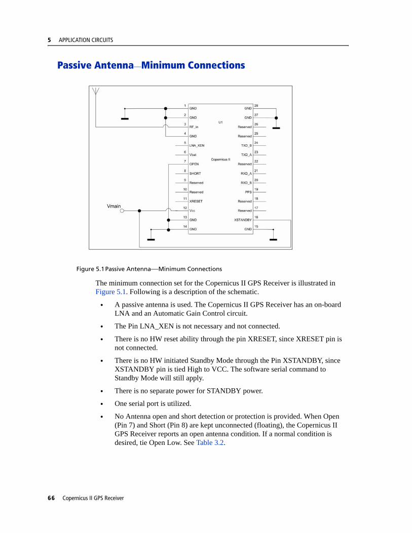
5 APPLICATION CIRCUITS
Passive Antenna—Minimum Connections
Figure 5.1Passive Antenna—Minimum Connections
The minimum connection set for the Copernicus II GPS Receiver is illustrated in Figure 5.1. Following is a description of the schematic.
• A passive antenna is used. The Copernicus II GPS Receiver has an on-board LNA and an Automatic Gain Control circuit.
• The Pin LNA_XEN is not necessary and not connected.
• There is no HW reset ability through the pin XRESET, since XRESET pin is not connected.
• There is no HW initiated Standby Mode through the Pin XSTANDBY, since XSTANDBY pin is tied High to VCC. The software serial command to Standby Mode will still apply.
• There is no separate power for STANDBY power.
• One serial port is utilized.
• No Antenna open and short detection or protection is provided. When Open (Pin 7) and Short (Pin 8) are kept unconnected (floating), the Copernicus II GPS Receiver reports an open antenna condition. If a normal condition is desired, tie Open Low. See Table 3.2.
66 Copernicus II GPS Receiver
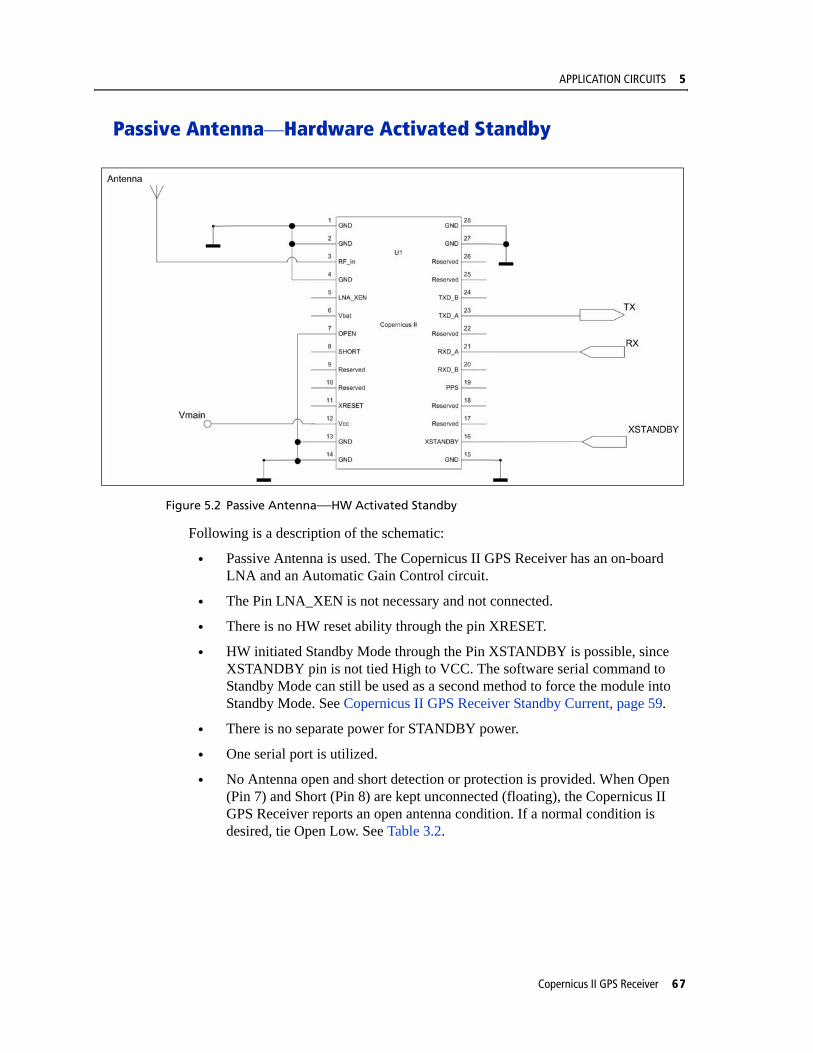
APPLICATION CIRCUITS 5
Passive Antenna—Hardware Activated Standby
Figure 5.2 Passive Antenna—HW Activated Standby
Following is a description of the schematic:
• Passive Antenna is used. The Copernicus II GPS Receiver has an on-board LNA and an Automatic Gain Control circuit.
• The Pin LNA_XEN is not necessary and not connected.
• There is no HW reset ability through the pin XRESET.
• HW initiated Standby Mode through the Pin XSTANDBY is possible, since XSTANDBY pin is not tied High to VCC. The software serial command to Standby Mode can still be used as a second method to force the module into Standby Mode. See Copernicus II GPS Receiver Standby Current, page 59.
• There is no separate power for STANDBY power.
• One serial port is utilized.
• No Antenna open and short detection or protection is provided. When Open (Pin 7) and Short (Pin 8) are kept unconnected (floating), the Copernicus II GPS Receiver reports an open antenna condition. If a normal condition is desired, tie Open Low. See Table 3.2.
Copernicus II GPS Receiver 67
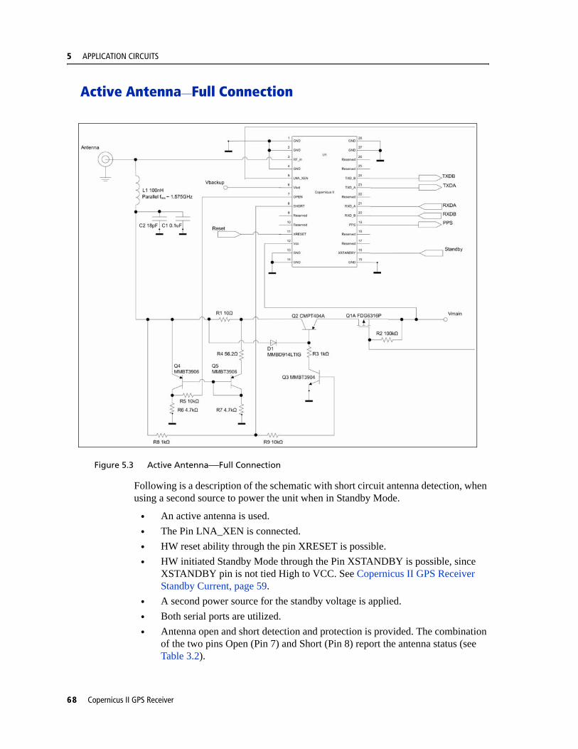
5 APPLICATION CIRCUITS
Active Antenna—Full Connection
Figure 5.3 Active Antenna—Full Connection
Following is a description of the schematic with short circuit antenna detection, when using a second source to power the unit when in Standby Mode.
• An active antenna is used. • The Pin LNA_XEN is connected.• HW reset ability through the pin XRESET is possible.• HW initiated Standby Mode through the Pin XSTANDBY is possible, since
XSTANDBY pin is not tied High to VCC. See Copernicus II GPS Receiver Standby Current, page 59.
• A second power source for the standby voltage is applied.• Both serial ports are utilized.• Antenna open and short detection and protection is provided. The combination
of the two pins Open (Pin 7) and Short (Pin 8) report the antenna status (see Table 3.2).
68 Copernicus II GPS Receiver

APPLICATION CIRCUITS 5
Table 5.2 Full Connection—Component Information
Component Description Manufacturer Part Number
C1 0.1 uF, 0402 capacitor, X7R
CAL-CHIP GMC04X7R104K16NTLF
C2 18 PF, 0402 capacitor, C0G
KEMET C0402C180J5GAC
Q1A P-Channel MOSFET Fairchild FDG6316P
J1 MCX Connector Johnson Components 133-3711-312
L1 100 nH, 0603 inductor, surface mount
Coil Craft 0603CS - R10XJLU
Q2 PNP Transistor Central Semiconductor CMPT404A (MMBTA70LT1 may be used if 12 Volt back voltage tolerance is not required)
Q3 NPN Transistor Philips MMBT3904
Q4 PNP Transistor Philips MMBT3906
Q5 PNP Transistor Philips MMBT3906
DI Switching Diode ON Semiconductor MMBD914LTIG
Copernicus II GPS Receiver 69
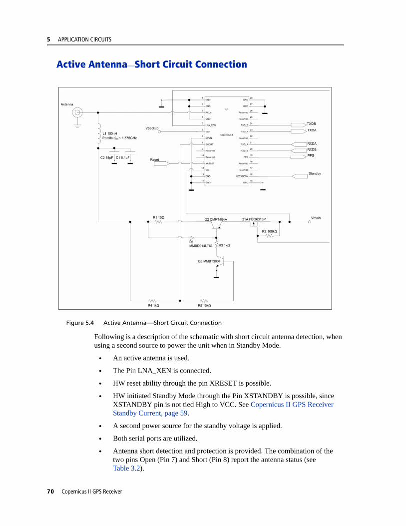
5 APPLICATION CIRCUITS
Active Antenna—Short Circuit Connection
Figure 5.4 Active Antenna—Short Circuit Connection
Following is a description of the schematic with short circuit antenna detection, when using a second source to power the unit when in Standby Mode.
• An active antenna is used.
• The Pin LNA_XEN is connected.
• HW reset ability through the pin XRESET is possible.
• HW initiated Standby Mode through the Pin XSTANDBY is possible, since XSTANDBY pin is not tied High to VCC. See Copernicus II GPS Receiver Standby Current, page 59.
• A second power source for the standby voltage is applied.
• Both serial ports are utilized.
• Antenna short detection and protection is provided. The combination of the two pins Open (Pin 7) and Short (Pin 8) report the antenna status (see Table 3.2).
70 Copernicus II GPS Receiver
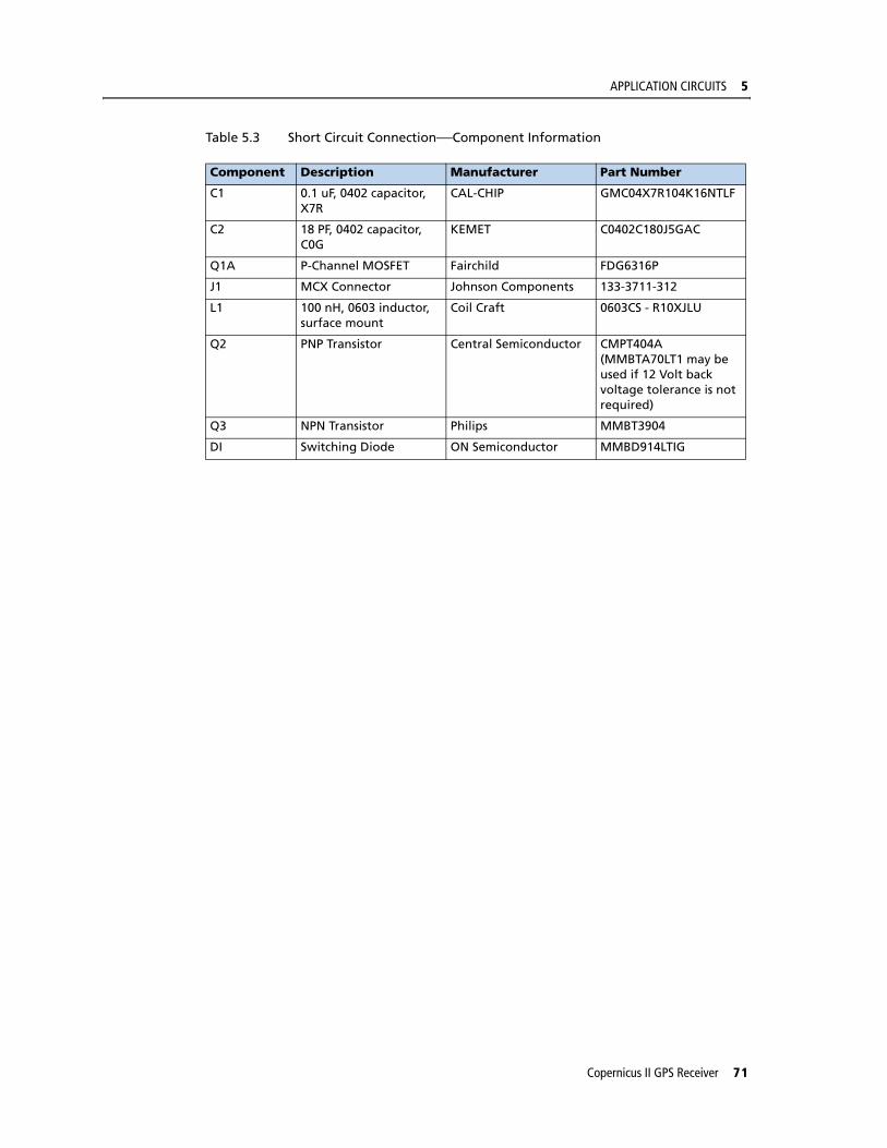
APPLICATION CIRCUITS 5
Table 5.3 Short Circuit Connection—Component Information
Component Description Manufacturer Part Number
C1 0.1 uF, 0402 capacitor, X7R
CAL-CHIP GMC04X7R104K16NTLF
C2 18 PF, 0402 capacitor, C0G
KEMET C0402C180J5GAC
Q1A P-Channel MOSFET Fairchild FDG6316P
J1 MCX Connector Johnson Components 133-3711-312
L1 100 nH, 0603 inductor, surface mount
Coil Craft 0603CS - R10XJLU
Q2 PNP Transistor Central Semiconductor CMPT404A (MMBTA70LT1 may be used if 12 Volt back voltage tolerance is not required)
Q3 NPN Transistor Philips MMBT3904
DI Switching Diode ON Semiconductor MMBD914LTIG
Copernicus II GPS Receiver 71
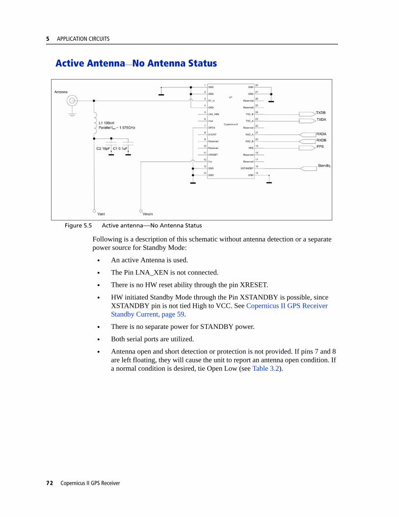
5 APPLICATION CIRCUITS
Active Antenna—No Antenna Status
Figure 5.5 Active antenna—No Antenna Status
Following is a description of this schematic without antenna detection or a separate power source for Standby Mode:
• An active Antenna is used.
• The Pin LNA_XEN is not connected.
• There is no HW reset ability through the pin XRESET.
• HW initiated Standby Mode through the Pin XSTANDBY is possible, since XSTANDBY pin is not tied High to VCC. See Copernicus II GPS Receiver Standby Current, page 59.
• There is no separate power for STANDBY power.
• Both serial ports are utilized.
• Antenna open and short detection or protection is not provided. If pins 7 and 8 are left floating, they will cause the unit to report an antenna open condition. If a normal condition is desired, tie Open Low (see Table 3.2).
72 Copernicus II GPS Receiver

C H A P T E R
6
RF LAYOUT CONSIDERATIONS 6In this chapter:
General Recommendations
Design considerations for RF Track Topologies
PCB Considerations
This chapter outlines RF design considerations for the Copernicus II GPS Receiver.
Copernicus II GPS Receiver 73

6 RF LAYOUT CONSIDERATIONS
General Recommendations The design of the RF transmission line that connects the GPS antenna to the Copernicus II GPS Receiver is critical to system performance. If the overall RF system is not implemented correctly, the Copernicus II GPS Receiver performance may be degraded.
The radio frequency (RF) input on the Copernicus II GPS module is a 50 ohm, unbalanced input. There are ground castellations, pins 2 and 4, on both sides of the RF input castellation, on pin 3. This RF input may be connected to the output of an LNA which has a GPS antenna at its input or to a passive antenna via a low-loss 50 ohm, unbalanced transmission line system.
In the case where the GPS antenna must be located any significant distance from the Copernicus II GPS Receiver, the use of an LNA at the antenna location is necessary to overcome the transmission losses from the antenna to the Copernicus II GPS module. It is recommended that in the case of a passive antenna, the transmission line losses from the antenna to the module be less than 2 dB. Otherwise an LNA should be added to the system.
The specifications for the external LNA required can be determined as follows. The specification of noise figure for the Copernicus II GPS module is 3 dB at room temperature and 4 dB over the temperature range −40 C to ±85 C. The noise figure for this external LNA should be as low as possible, with a recommended maximum of 1.5 dB. It is recommended that the gain of this LNA exceed the loss as measured from the LNA output to the module input by 10 dB. For example, if the loss from the external LNA output is 10 dB, the recommended minimum gain for the LNA is 20 dB. In order to keep losses at the LNA input to a minimum, it is recommended that the antenna be connected directly to the LNA input, with as minimum loss as possible.
Connections to either the LNA output or to a passive antenna must be made using a 50 ohm unbalanced transmission system. This transmission system may take any form, such as microstrip, coaxial, stripline or any 50 ohm characteristic impedance unbalanced, low-loss system.
It is important to keep any noise sources with frequencies at or near 1575 MHz away from the RF input. In the case of a passive antenna, it is important that the antenna is not placed in a noisy location (such as too close to digital circuitry) or performance may be degraded. Shielded transmission line systems (stripline, coaxial) may be used to route this signal if noise ingress is a concern.
If an active antenna is used and it is desired to power this antenna from the RF transmission line, a bias-tee will be required at the Copernicus II GPS module end. A simple series inductor (that is parallel resonant at 1575 MHz) and shunt capacitor (series resonant at 1575 MHz) to which the bias voltage is supplied is sufficient. An open/short detection and over current protection circuit may also be employed. Please see Chapter 5, APPLICATION CIRCUITS.
74 Copernicus II GPS Receiver
RF LAYOUT CONSIDERATIONS 6
In the printed circuit board (PCB) layout, it is recommended to keep the copper layer on which the Copernicus II GPS Receiver is mounted clear of solder mask and copper (vias or traces) under the module. This is to insure mating of the castellations between the Copernicus II GPS module and the board to which it is mounted, and that there is no interference with features beneath the Copernicus II GPS Receiver causing it to lift during the re-flow solder process.
For a microstrip RF transmission line topology, it is recommended that the layer immediately below the one to which the Copernicus II GPS Receiver is mounted be ground plane. Pins 2 and 4 should be directly connected to this ground plane with low inductance connections. Pin 3, the RF input, can be routed on the top layer using the proper geometry for a 50 ohm system.
Copernicus II GPS Receiver 75
6 RF LAYOUT CONSIDERATIONS
Design considerations for RF Track TopologiesThe following items need to be considered for the Copernicus II GPS Receiver RF layout:
• PCB track connection to the RF antenna input must have impedance of 50 ohms.
• PCB track connection to the RF antenna input must be as short as possible.
• If an external antenna is used, PCB track connection to the RF antenna input must transition from the circuit board to the external antenna cable, which is typically a RF connector.
• If there are any ground planes on the same layer as the microstrip trace, please refer to the Coplaner Waveguide design. Not covered in this manual.
• PCB track connection to the RF antenna input must be routed away from potential noise sources such as oscillators, transmitters, digital circuits, switching power supplies and other sources of noise.
• RF and bypass grounding must be direct to the ground plane through its own low-inductance via
• Active or passive antennas may be used. If using a passive antenna the connection to the antenna input shall be very short. It is possible to mount the patch antenna on the same PCB as the Copernicus II GPS module. Designers must be aware of noise generating circuitry and proper design precautions taken (shielding,.).
The PCB track connection to the RF antenna input must not have:
• Sharp bends.
• Components overlaying the track.
• Routing between components to avoid undesirable coupling.
76 Copernicus II GPS Receiver
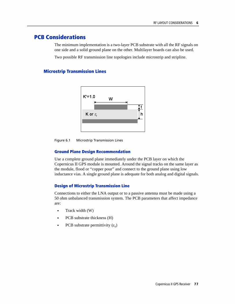
RF LAYOUT CONSIDERATIONS 6
PCB ConsiderationsThe minimum implementation is a two-layer PCB substrate with all the RF signals on one side and a solid ground plane on the other. Multilayer boards can also be used.
Two possible RF transmission line topologies include microstrip and stripline.
Microstrip Transmission Lines
Figure 6.1 Microstrip Transmission Lines
Ground Plane Design Recommendation
Use a complete ground plane immediately under the PCB layer on which the Copernicus II GPS module is mounted. Around the signal tracks on the same layer as the module, flood or “copper pour” and connect to the ground plane using low inductance vias. A single ground plane is adequate for both analog and digital signals.
Design of Microstrip Transmission Line
Connections to either the LNA output or to a passive antenna must be made using a 50 ohm unbalanced transmission system. The PCB parameters that affect impedance are:
• Track width (W)
• PCB substrate thickness (H)
• PCB substrate permittivity (εr)
Copernicus II GPS Receiver 77

6 RF LAYOUT CONSIDERATIONS
• To a lesser extent, PCB copper thickness (T) and proximity of same layer ground plane.
Figure 6.2 PCB Microstrip Topology
Table 6.1 shows typical track widths for an FR4 material PCB substrate (permittivity εr of 4.6 at 1.5 GHz) and different PCB thickness. One ounce copper is assumed for the thickness of the top layer. If a Multi layer PCB is used, the thickness is the distance from signal track to nearest ground plane.
Table 6.1 Typical Track Widths for an FR4 material PCB Substrate in Microstrip Topology
Microstrip Design Recommendations
It is recommended that the antenna connection PCB track be routed around the outside of the module outline, kept on a single layer and have no bends greater than 45 degrees. It is not recommended, for production reasons, to route the track under the module.
Substrate Material Permittivity Substrate ThicknessH (mm)
Track WidthW (MM)
1.6 2.91
1.2 2.12
1.0 1.81
FR4 4.6 0.8 1.44
0.6 1.07
0.4 0.71
0.2 0.34
78 Copernicus II GPS Receiver
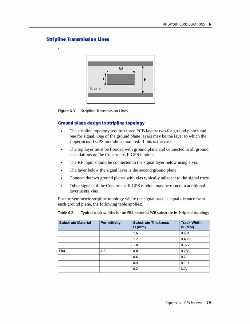
RF LAYOUT CONSIDERATIONS 6
Stripline Transmission Lines
.
Figure 6.3 Stripline Transmission Lines
Ground plane design in stripline topology
• The stripline topology requires three PCB layers: two for ground planes and one for signal. One of the ground plane layers may be the layer to which the Copernicus II GPS module is mounted. If this is the case,
• The top layer must be flooded with ground plane and connected to all ground castellations on the Copernicus II GPS module.
• The RF input should be connected to the signal layer below using a via.
• The layer below the signal layer is the second ground plane.
• Connect the two ground planes with vias typically adjacent to the signal trace.
• Other signals of the Copernicus II GPS module may be routed to additional layer using vias.
For the symmetric stripline topology where the signal trace is equal distance from each ground plane, the following table applies:.
Table 6.2 Typical track widths for an FR4 material PCB substrate in Stripline topology
Substrate Material Permittivity Substrate ThicknessH (mm)
Track WidthW (MM)
1.6 0.631
1.2 0.438
1.0 0.372
FR4 4.6 0.8 0.286
0.6 0.2
0.4 0.111
0.2 N/A
Copernicus II GPS Receiver 79

6 RF LAYOUT CONSIDERATIONS
80 Copernicus II GPS Receiver

C H A P T E R
7
MECHANICAL SPECIFICATIONS 7In this chapter:
Mechanical Outline Drawing
Soldering the Copernicus II GPS Receiver to a PCB
This chapter provides product drawings and instructions for soldering the Copernicus II GPS Receiver to a PCB.
Copernicus II GPS Receiver 81
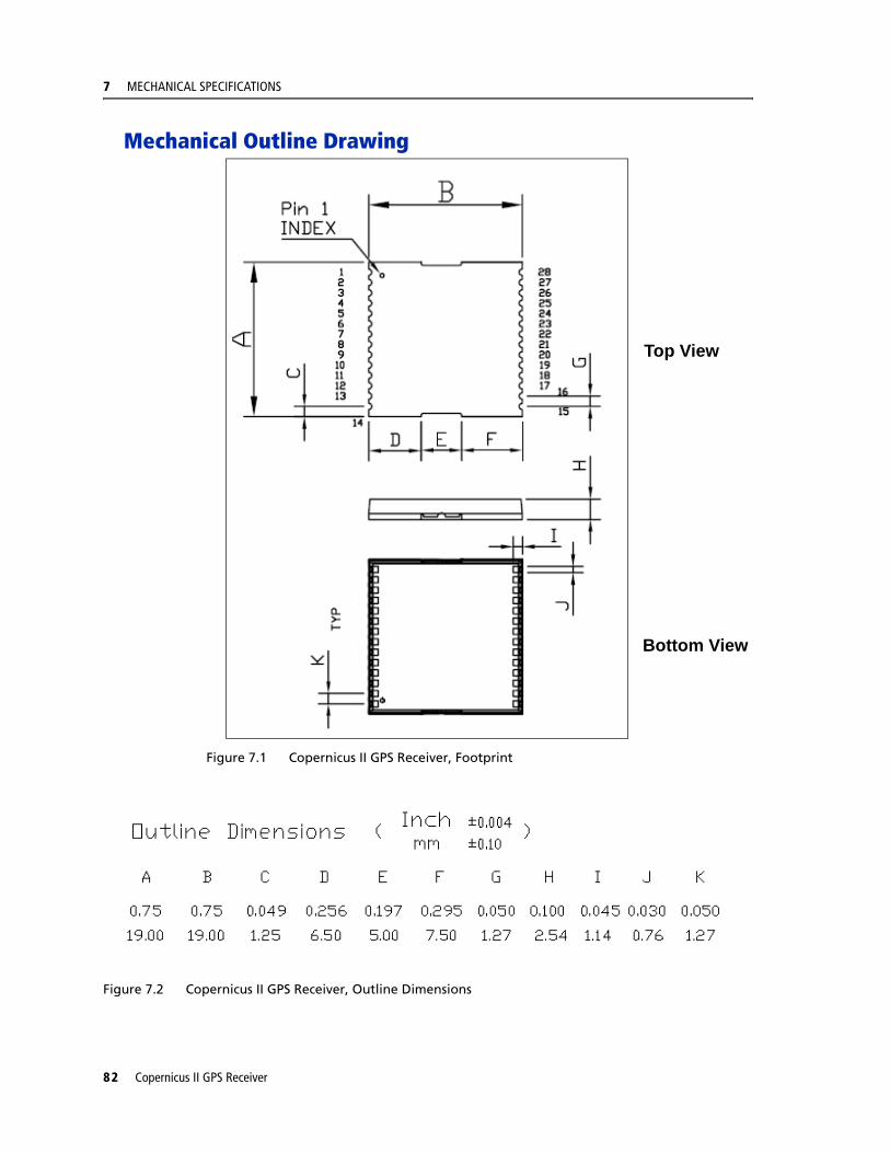
7 MECHANICAL SPECIFICATIONS
Mechanical Outline Drawing
Figure 7.1 Copernicus II GPS Receiver, Footprint
Figure 7.2 Copernicus II GPS Receiver, Outline Dimensions
IMAGE TO COMETop View
Bottom View
82 Copernicus II GPS Receiver
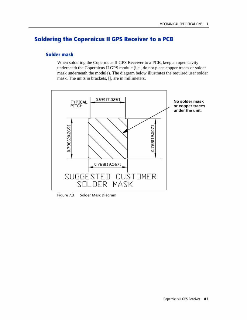
MECHANICAL SPECIFICATIONS 7
Soldering the Copernicus II GPS Receiver to a PCB
Solder mask
When soldering the Copernicus II GPS Receiver to a PCB, keep an open cavity underneath the Copernicus II GPS module (i.e., do not place copper traces or solder mask underneath the module). The diagram below illustrates the required user solder mask. The units in brackets, [], are in millimeters.
Figure 7.3 Solder Mask Diagram
No solder maskor copper tracesunder the unit.
Copernicus II GPS Receiver 83

7 MECHANICAL SPECIFICATIONS
Pad Pattern
Below is the required user pad pattern. The units in brackets, [], are in millimeters.
Figure 7.4 Pad Pattern Diagram
No solder maskor copper tracesunder the unit.
84 Copernicus II GPS Receiver
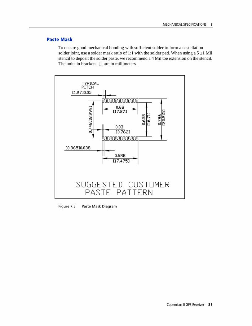
MECHANICAL SPECIFICATIONS 7
Paste Mask
To ensure good mechanical bonding with sufficient solder to form a castellation solder joint, use a solder mask ratio of 1:1 with the solder pad. When using a 5 ±1 Mil stencil to deposit the solder paste, we recommend a 4 Mil toe extension on the stencil. The units in brackets, [], are in millimeters.
Figure 7.5 Paste Mask Diagram
Copernicus II GPS Receiver 85

7 MECHANICAL SPECIFICATIONS
86 Copernicus II GPS Receiver

C H A P T E R
8
PACKAGING 8In this chapter:
Introduction
Reel
Tapes
Follow the instructions in this chapter to ensure the integrity of the packaged and shipped Copernicus II GPS Receiver modules.
Copernicus II GPS Receiver 87
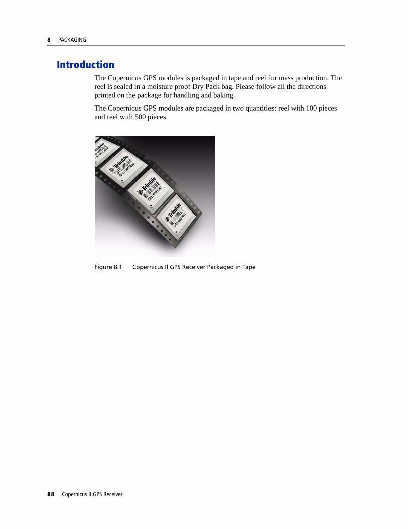
8 PACKAGING
IntroductionThe Copernicus GPS modules is packaged in tape and reel for mass production. The reel is sealed in a moisture proof Dry Pack bag. Please follow all the directions printed on the package for handling and baking.
The Copernicus GPS modules are packaged in two quantities: reel with 100 pieces and reel with 500 pieces.
Figure 8.1 Copernicus II GPS Receiver Packaged in Tape
88 Copernicus II GPS Receiver
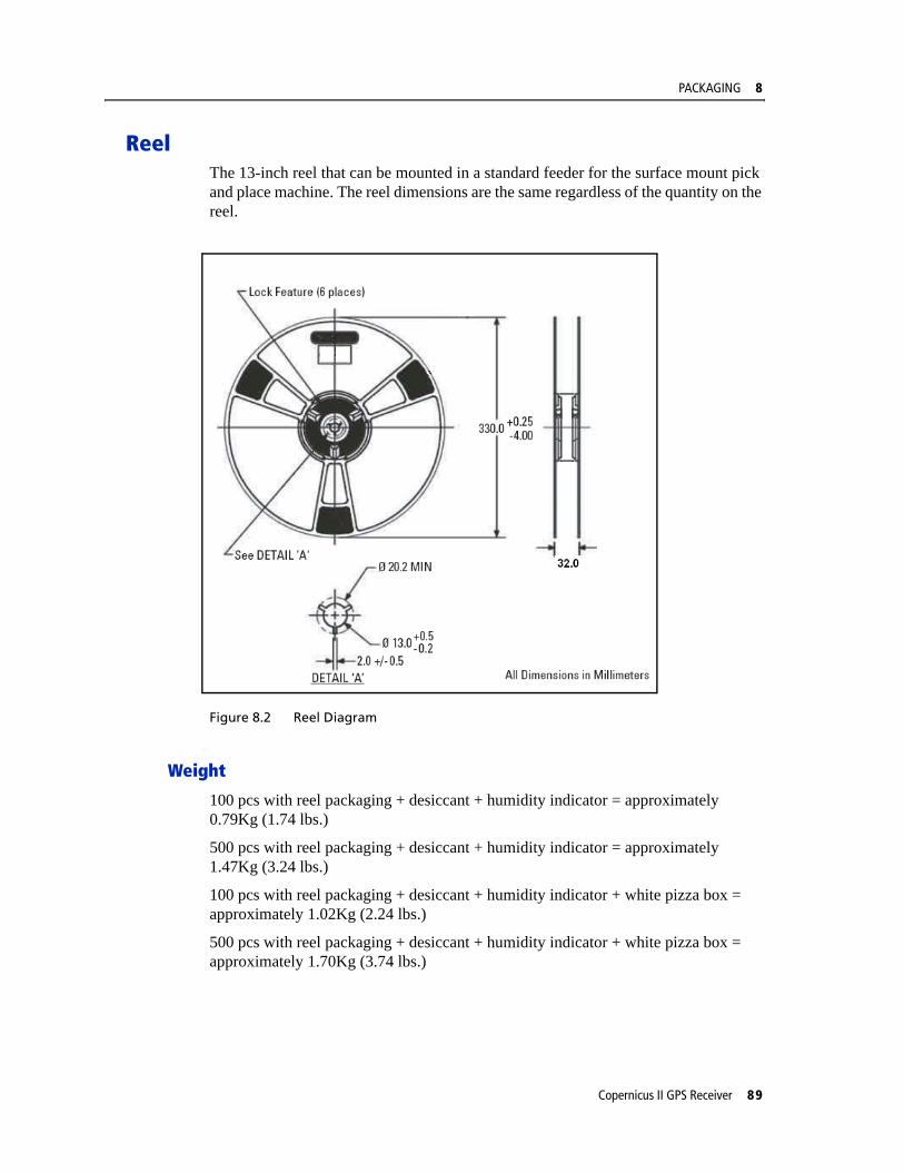
PACKAGING 8
ReelThe 13-inch reel that can be mounted in a standard feeder for the surface mount pick and place machine. The reel dimensions are the same regardless of the quantity on the reel.
Figure 8.2 Reel Diagram
Weight
100 pcs with reel packaging + desiccant + humidity indicator = approximately 0.79Kg (1.74 lbs.)
500 pcs with reel packaging + desiccant + humidity indicator = approximately 1.47Kg (3.24 lbs.)
100 pcs with reel packaging + desiccant + humidity indicator + white pizza box = approximately 1.02Kg (2.24 lbs.)
500 pcs with reel packaging + desiccant + humidity indicator + white pizza box = approximately 1.70Kg (3.74 lbs.)
Copernicus II GPS Receiver 89

8 PACKAGING
TapesThe tape dimensions illustrated in the diagram below are in inches. The metric units appear in brackets [].
Figure 8.3 Tape Diagram
Figure 8.4 Feeding Direction Diagram
Feeding direction
ROUND HOLE
S/N 05011234
52979-00-D
Made in China
52979-00-D
S/N 05011234
Made in China
S/N 05011234
52979-00-D
Made in China
S/N 05011234
52979-00-D
Made in China
S/N 05011234
52979-00-D
Made in China
S/N 05011234
52979-00-D
Made in China
90 Copernicus II GPS Receiver

C H A P T E R
9
SHIPPING and HANDLING 9In this chapter:
Shipping and Handling Guidelines
Moisture Precondition
Baking Procedure
Soldering Paste
Solder Reflow
Recommended Soldering Profile
Optical Inspection
Cleaning
Soldering Guidelines
Rework
Conformal Coating
Grounding the Metal Shield
This chapter provides detailed guidelines for shipping and handling the Copernicus II GPS Receiver to ensure compliance with the product warranty.
Copernicus II GPS Receiver 91
9 SHIPPING and HANDLING
Shipping and Handling Guidelines
Handling
The Copernicus II GPS module is shipped in tape and reel for use with an automated surface mount machine. This is a lead-free module with silver plating. Do not allow bodily fluids or lotions to come in contact with the bottom of the module.
C WARNING – The Copernicus II GPS module is packed according to ANSI/EIA-481-B and J-STD-033A. All of the handling and precaution procedures must be followed. Deviation from following handling procedures and precautions voids the warranty.
Shipment
The reel of Copernicus II GPS modules is packed in a hermetically sealed moisture barrier bag (DryPac) then placed in an individual carton. Handle with care to avoid breaking the moisture barrier.
Storage
The shelf life for the sealed DryPac is 12 months and it must be stored at <40 °C and <90% relative humidity.
Moisture Indicator
A moisture indicator is packed individually in each DryPac to monitor the environment. All five indicating spots are shown blue from the factory. If the indicator shows pink, follow the instructions printed on the indicator and bake as necessary. See Baking Procedure, page 94 for baking instructions.
Floor Life
The reel of Copernicus II GPS modules is vacuum sealed in a moisture barrier bag (DryPac). Once the bag is opened, moisture will bond with the modules. In a production floor environment, an open reel needs to be processed within 72 hours, unless it is kept in a nitrogen purged dry chamber. If the moisture indicator has changed to pink, follow the baking instructions printed on the moisture barrier.
The Copernicus II GPS is a lead free component for RoHS compliance. This unit is also plated with immersion silver for better solderability. The silver may tarnish over time and show yellow in color, but tarnish should not affect the solderability.
C WARNING – Operators should not touch the bottom silver solder pads by hand or with contaminated gloves. No hand lotion or regular chlorinated faucet water can be in contact with this module before soldering.
92 Copernicus II GPS Receiver
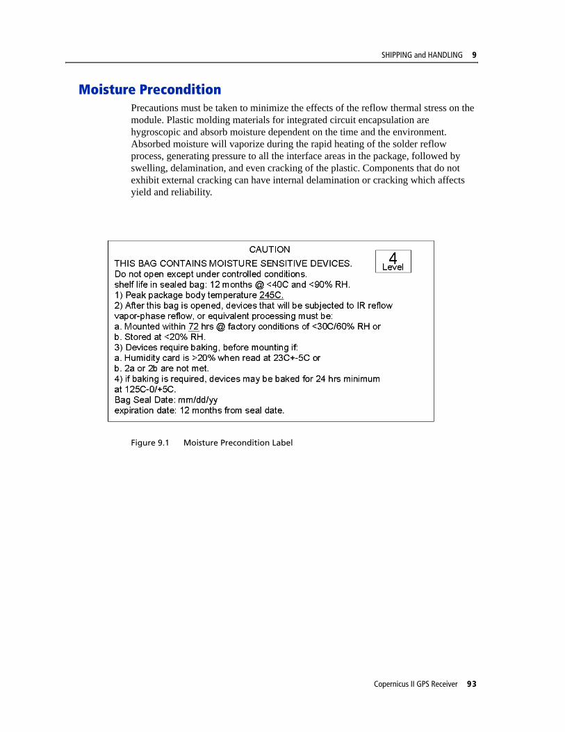
SHIPPING and HANDLING 9
Moisture PreconditionPrecautions must be taken to minimize the effects of the reflow thermal stress on the module. Plastic molding materials for integrated circuit encapsulation are hygroscopic and absorb moisture dependent on the time and the environment. Absorbed moisture will vaporize during the rapid heating of the solder reflow process, generating pressure to all the interface areas in the package, followed by swelling, delamination, and even cracking of the plastic. Components that do not exhibit external cracking can have internal delamination or cracking which affects yield and reliability.
Figure 9.1 Moisture Precondition Label
Copernicus II GPS Receiver 93

9 SHIPPING and HANDLING
Baking ProcedureIf baking is necessary, Trimble recommends baking in a nitrogen purge oven.
Temperature: 125 °C
Duration: 24 Hours.
After Baking: Store in a nitrogen-purged cabinet or dry box to prevent absorption of moisture.
C WARNING – Do not bake the units within the tape and reel packaging. Repeated baking processes will reduce the solderablity.
Soldering PasteThe Copernicus II GPS module itself is not hermetically sealed, Trimble strongly recommends using the “No Clean” soldering paste and process. The castellation solder pad on this module is plated with silver plating. Use Type 3 or above soldering paste to maximize the solder volume. An example is provided below.
Solder paste: Kester EM909
Alloy composition: Sn96.5Ag3Cu.5 (SAC305) 96.5% Tin/ 3%Silver/ 0.5% Copper
Liquid Temperature: 221 °C
Stencil Thickness: 5 Mil (0.005")
Stencil opening requires 4-mil toe over paste in the X and Y directions.
Note – Consult solder paste manufacturer and the assembly process for the approved procedures.
Solder ReflowA hot air convection oven is strongly recommended for solder reflow. For the lead-free solder reflow, we recommend using a nitrogen-purged oven to increase the solder wetting. Reference IPC-610D for the lead free solder surface appearance.
C WARNING – Follow the thermal reflow guidelines from the IPC-JEDEC J-STD-020C.
The size of this module is 916.9 mm3. According to J-STD-020C, the peak component temperature during reflow is 245 +0 °C.
94 Copernicus II GPS Receiver
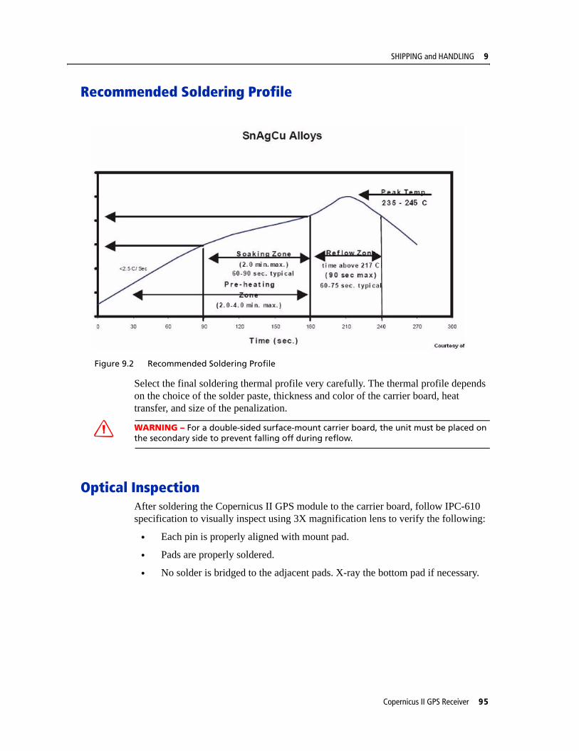
SHIPPING and HANDLING 9
Recommended Soldering Profile
Figure 9.2 Recommended Soldering Profile
Select the final soldering thermal profile very carefully. The thermal profile depends on the choice of the solder paste, thickness and color of the carrier board, heat transfer, and size of the penalization.
C WARNING – For a double-sided surface-mount carrier board, the unit must be placed on the secondary side to prevent falling off during reflow.
Optical InspectionAfter soldering the Copernicus II GPS module to the carrier board, follow IPC-610 specification to visually inspect using 3X magnification lens to verify the following:
• Each pin is properly aligned with mount pad.
• Pads are properly soldered.
• No solder is bridged to the adjacent pads. X-ray the bottom pad if necessary.
Copernicus II GPS Receiver 95

9 SHIPPING and HANDLING
CleaningWhen the Copernicus II GPS module is attached to the user board, a cleaning process voids the warranty. Please use a “no-clean” process to eliminate the cleaning process. The silver plated Copernicus II GPS module may discolor with cleaning agent or chlorinated faucet water. Any other form of cleaning solder residual may cause permanent damage and will void the warranty.
Soldering Guidelines
Repeated Reflow Soldering
The Copernicus II GPS lead-free silver plated module can withstand two-reflow solder processes. If the unit must mount on the first side for surface-mount reflow, add glue on the bottom of the module to prevent falling off when processing the second side.
Wave Soldering
The Copernicus II GPS module cannot soak in the solder pot. If the carrier board is mixed with through-hole components and surface mount devices, it can be processed with one single lead-free wave process. The temperature of the unit will depend on the size and the thickness of the board. Measure the temperature on the module to ensure that it remains under 180 °C.
Hand Soldering
For the lead-free Copernicus II GPS module, use a lead-free solder core, such as Kester 275 Sn96.5/Ag3/Cu0.5. When soldering the module by hand, keep the soldering iron below 260 °C.
Rework The Copernicus II GPS module can withstand one rework cycle. The module can heat up to the reflow temperature to precede the rework. Never remove the metal shield and rework on the module itself.
Conformal CoatingConformal coating on the Copernicus II GPS module is not allowed. Conformal coating will void the warranty.
96 Copernicus II GPS Receiver

SHIPPING and HANDLING 9
Grounding the Metal ShieldThe Copernicus II GPS Receiver is designed with numerous ground pins that, along with the metal shield, provide the best immunity to EMI and noise. Any alteration by adding ground wires to the metal shield is done at the customer's own risk and may void the warranty.
Copernicus II GPS Receiver 97

9 SHIPPING and HANDLING
98 Copernicus II GPS Receiver
C H A P T E R
10
COPERNICUS II REFERENCE BOARD 10In this chapter:
Reference Board Block Diagram
Reference Board Schematic (page 1 of 3)
Reference Board Schematic (page 2 of 3)
Reference Board Schematic (page 3 of 3)
Reference Board I/O and Power Connector
Reference Board Power Requirement
Reference Board Component Locations Drawing
This chapter provides schematics for the Copernicus II GPS Receiver board.
Copernicus II GPS Receiver 99

10 COPERNICUS II REFERENCE BOARD
IntroductionThe Copernicus II GPS surface-mount receiver is installed on a carrier board defined as the Copernicus II GPS Reference Board. This board can also be used as a design reference, providing a visual layout of the Copernicus II GPS module on a PCB including the RF signal trace, RF connector, and the I/O connections of the 28 signal pins. The reference board demonstrates how an 8-pin header connector can be connected to the I/O and power sections of Copernicus II GPS, and how an RF connector can be attached to the RF section. An antenna open and short detection and protection application circuit has also been included on the reference board. The Copernicus II GPS reference board is RoHS compliant (lead-free).
Figure 10.1 Copernicus II GPS Reference Board
The Copernicus II GPS reference board is installed on the starter kit motherboard to facilitate testing and evaluation of the Copernicus II GPS Receiver. It provides everything the user needs to get started integrating state-of-the-art GPS capability into an application.
100 Copernicus II GPS Receiver
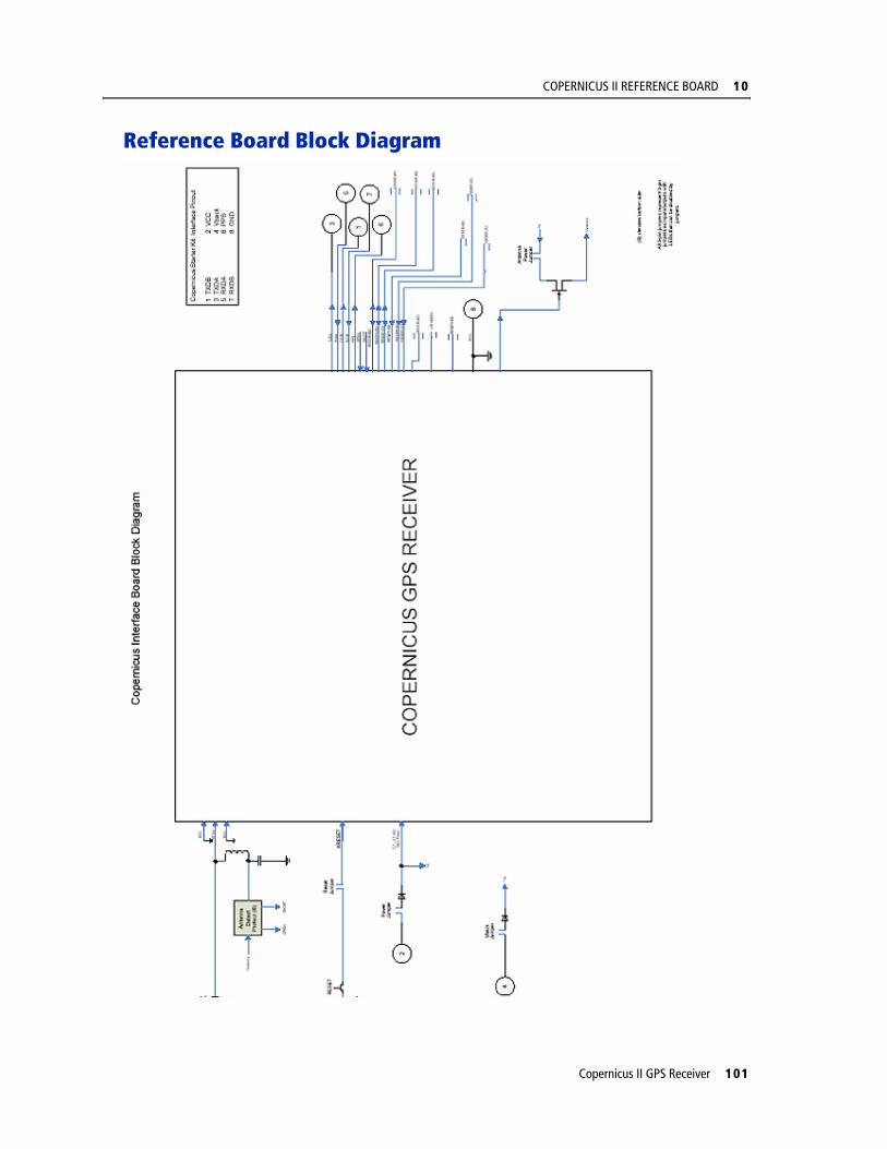
COPERNICUS II REFERENCE BOARD 10
Reference Board Block Diagram
Copernicus II GPS Receiver 101
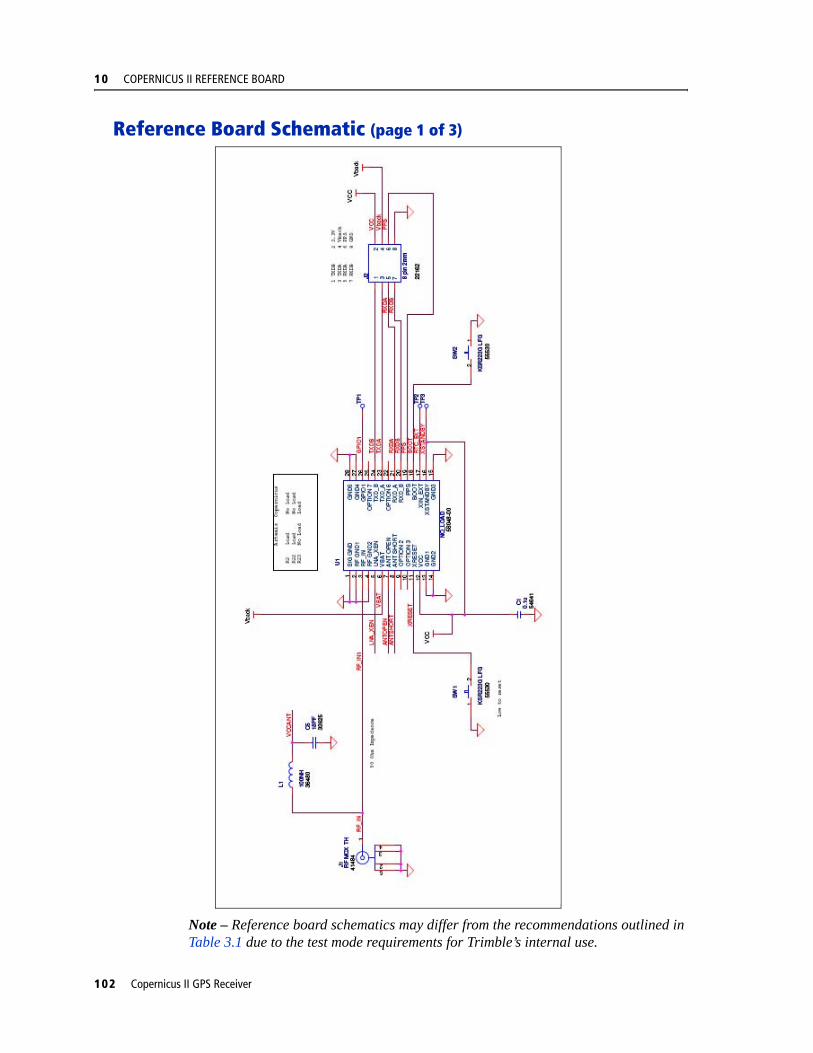
10 COPERNICUS II REFERENCE BOARD
Reference Board Schematic (page 1 of 3)
Note – Reference board schematics may differ from the recommendations outlined in Table 3.1 due to the test mode requirements for Trimble’s internal use.
102 Copernicus II GPS Receiver
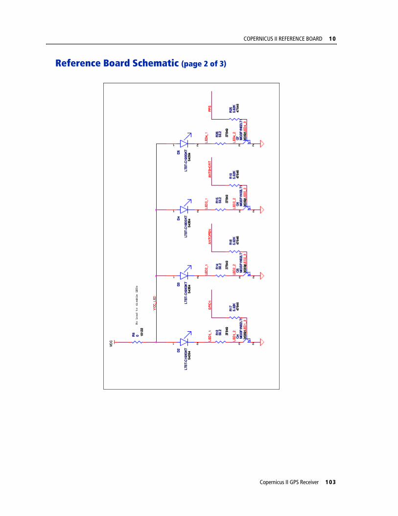
COPERNICUS II REFERENCE BOARD 10
Reference Board Schematic (page 2 of 3)
Copernicus II GPS Receiver 103

10 COPERNICUS II REFERENCE BOARD
Reference Board Schematic (page 3 of 3)
Figure 10.2 Copernicus II GPS Reference Board Schematic (Page 3)
104 Copernicus II GPS Receiver
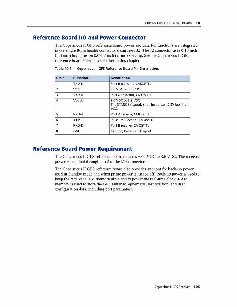
COPERNICUS II REFERENCE BOARD 10
Reference Board I/O and Power ConnectorThe Copernicus II GPS reference board power and data I/O functions are integrated into a single 8-pin header connector designated J2. The J2 connector uses 0.15 inch (3.8 mm) high pins on 0.0787 inch (2 mm) spacing. See the Copernicus II GPS reference board schematics, earlier in this chapter.
Table 10.1 Copernicus II GPS Reference Board Pin Description.
Reference Board Power RequirementThe Copernicus II GPS reference board requires +3.0 VDC to 3.6 VDC. The receiver power is supplied through pin 2 of the I/O connector.
The Copernicus II GPS reference board also provides an input for back-up power used in Standby mode and when prime power is turned off. Back-up power is used to keep the receiver RAM memory alive and to power the real-time clock. RAM memory is used to store the GPS almanac, ephemeris, last position, and user configuration data, including port parameters.
Pin # Function Description1 TXD-B Port B transmit, CMOS/TTL
2 VCC 3.0 VDC to 3.6 VDC
3 TXD-A Port A transmit, CMOS/TTL
4 Vback 3.0 VDC to 3.3 VDC The STANDBY supply shall be at least 0.3V less than VCC.
5 RXD-A Port A receive, CMOS/TTL
6 1 PPS Pulse-Per-Second, CMOS/TTL
7 RXD-B Port B receive, CMOS/TTL
8 GND Ground, Power and Signal
Copernicus II GPS Receiver 105

10 COPERNICUS II REFERENCE BOARD
Reference Board Component Locations Drawing
Figure 10.3 Copernicus II GPS Reference Board, Top Side
Figure 10.4 Copernicus II GPS Reference Board Schematic, Bottom Side
106 Copernicus II GPS Receiver

C H A P T E R
11
FIRMWARE UPLOAD 11In this chapter:
Software Architecture
Boot Monitor
Firmware Binary File Format
Firmware Loading Procedure
Monitor Interface Protocol
FlashLoader Tool Reference Guide
This chapter describes an interface for programming (loading) firmware into the Copernicus II GPS Receiver. The interface can be used to develop a tool to upgrade firmware in the field. Sample source code of a tool for Microsoft® Windows is available to demonstrate implementation of the interface described in this document.
The information contained in this chapter is applicable only to the Copernicus II GPS receiver developed by the Advanced Devices group of Trimble Navigation Ltd. It may not be relevant to other products.
Copernicus II GPS Receiver 107
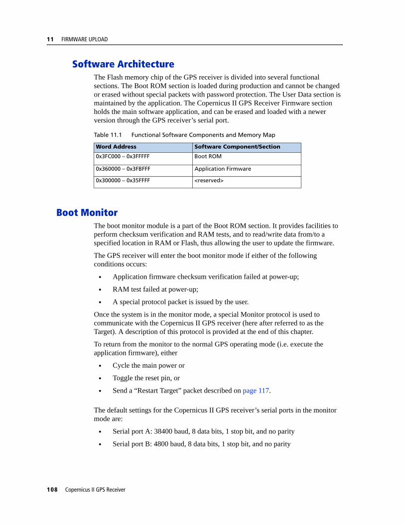
11 FIRMWARE UPLOAD
Software ArchitectureThe Flash memory chip of the GPS receiver is divided into several functional sections. The Boot ROM section is loaded during production and cannot be changed or erased without special packets with password protection. The User Data section is maintained by the application. The Copernicus II GPS Receiver Firmware section holds the main software application, and can be erased and loaded with a newer version through the GPS receiver’s serial port.
Boot MonitorThe boot monitor module is a part of the Boot ROM section. It provides facilities to perform checksum verification and RAM tests, and to read/write data from/to a specified location in RAM or Flash, thus allowing the user to update the firmware.
The GPS receiver will enter the boot monitor mode if either of the following conditions occurs:
• Application firmware checksum verification failed at power-up;
• RAM test failed at power-up;
• A special protocol packet is issued by the user.
Once the system is in the monitor mode, a special Monitor protocol is used to communicate with the Copernicus II GPS receiver (here after referred to as the Target). A description of this protocol is provided at the end of this chapter.
To return from the monitor to the normal GPS operating mode (i.e. execute the application firmware), either
• Cycle the main power or
• Toggle the reset pin, or
• Send a “Restart Target” packet described on page 117.
The default settings for the Copernicus II GPS receiver’s serial ports in the monitor mode are:
• Serial port A: 38400 baud, 8 data bits, 1 stop bit, and no parity
• Serial port B: 4800 baud, 8 data bits, 1 stop bit, and no parity
Table 11.1 Functional Software Components and Memory Map
Word Address Software Component/Section
0x3FC000 – 0x3FFFFF Boot ROM
0x360000 – 0x3FBFFF Application Firmware
0x300000 – 0x35FFFF <reserved>
108 Copernicus II GPS Receiver
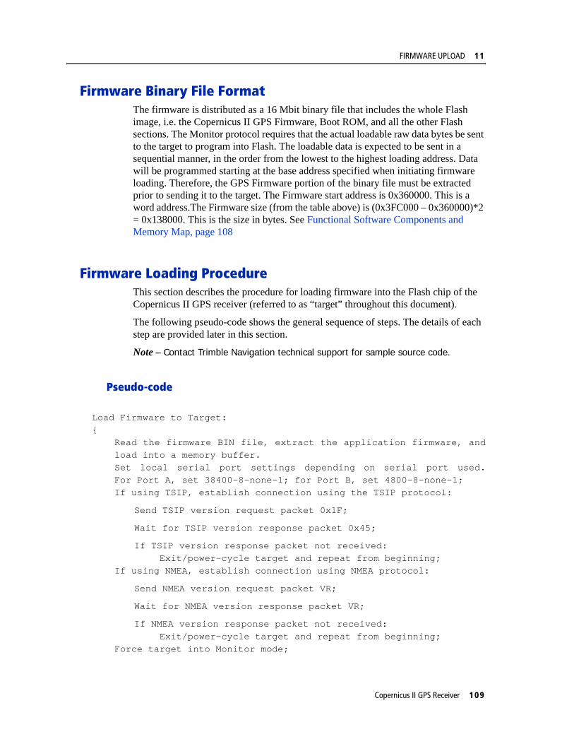
FIRMWARE UPLOAD 11
Firmware Binary File FormatThe firmware is distributed as a 16 Mbit binary file that includes the whole Flash image, i.e. the Copernicus II GPS Firmware, Boot ROM, and all the other Flash sections. The Monitor protocol requires that the actual loadable raw data bytes be sent to the target to program into Flash. The loadable data is expected to be sent in a sequential manner, in the order from the lowest to the highest loading address. Data will be programmed starting at the base address specified when initiating firmware loading. Therefore, the GPS Firmware portion of the binary file must be extracted prior to sending it to the target. The Firmware start address is 0x360000. This is a word address.The Firmware size (from the table above) is (0x3FC000 – 0x360000)*2 = 0x138000. This is the size in bytes. See Functional Software Components and Memory Map, page 108
Firmware Loading ProcedureThis section describes the procedure for loading firmware into the Flash chip of the Copernicus II GPS receiver (referred to as “target” throughout this document).
The following pseudo-code shows the general sequence of steps. The details of each step are provided later in this section.
Note – Contact Trimble Navigation technical support for sample source code.
Pseudo-code
Load Firmware to Target:{
Read the firmware BIN file, extract the application firmware, andload into a memory buffer.Set local serial port settings depending on serial port used.For Port A, set 38400-8-none-1; for Port B, set 4800-8-none-1;If using TSIP, establish connection using the TSIP protocol:
Send TSIP version request packet 0x1F;
Wait for TSIP version response packet 0x45;
If TSIP version response packet not received:Exit/power-cycle target and repeat from beginning;
If using NMEA, establish connection using NMEA protocol:
Send NMEA version request packet VR;
Wait for NMEA version response packet VR;
If NMEA version response packet not received:Exit/power-cycle target and repeat from beginning;
Force target into Monitor mode;
Copernicus II GPS Receiver 109
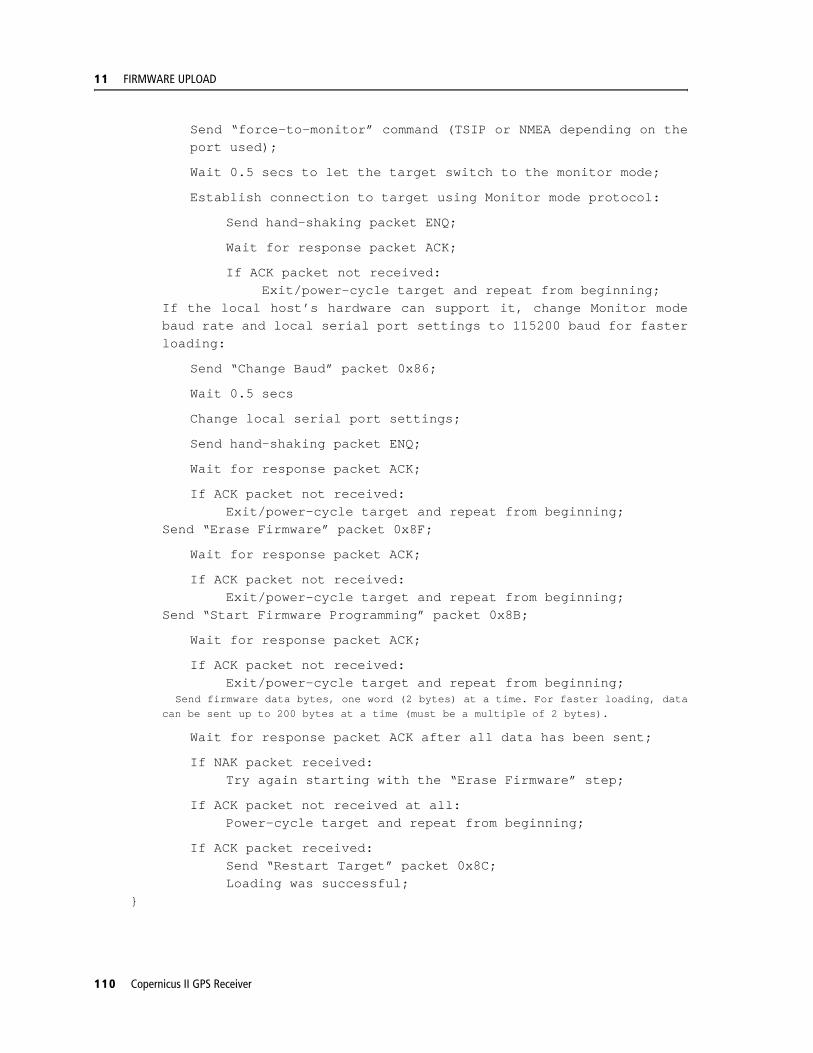
11 FIRMWARE UPLOAD
Send “force-to-monitor” command (TSIP or NMEA depending on theport used);
Wait 0.5 secs to let the target switch to the monitor mode;
Establish connection to target using Monitor mode protocol:
Send hand-shaking packet ENQ;
Wait for response packet ACK;
If ACK packet not received:Exit/power-cycle target and repeat from beginning;
If the local host’s hardware can support it, change Monitor modebaud rate and local serial port settings to 115200 baud for fasterloading:
Send “Change Baud” packet 0x86;
Wait 0.5 secs
Change local serial port settings;
Send hand-shaking packet ENQ;
Wait for response packet ACK;
If ACK packet not received:Exit/power-cycle target and repeat from beginning;
Send “Erase Firmware” packet 0x8F;
Wait for response packet ACK;
If ACK packet not received:Exit/power-cycle target and repeat from beginning;
Send “Start Firmware Programming” packet 0x8B;
Wait for response packet ACK;
If ACK packet not received:Exit/power-cycle target and repeat from beginning;
Send firmware data bytes, one word (2 bytes) at a time. For faster loading, datacan be sent up to 200 bytes at a time (must be a multiple of 2 bytes).
Wait for response packet ACK after all data has been sent;
If NAK packet received:Try again starting with the “Erase Firmware” step;
If ACK packet not received at all:Power-cycle target and repeat from beginning;
If ACK packet received:Send “Restart Target” packet 0x8C;Loading was successful;
}
110 Copernicus II GPS Receiver

FIRMWARE UPLOAD 11
Pseudo-Code Explanation
The following provides details about the steps shown in the above pseudo-code for the firmware loading procedure.
1. Read firmware BIN file and load into a memory buffer.(See Appendix A for an example function that shows how this is achieved.)
2. Establish a serial port connection to the target in the TSIP or NMEA mode.
Communication with the target over its serial port must be established first. Change the local host’s port settings to match those of the target. Refer to the GPS receiver’s user manual for details.
If using TSIP, issue a TSIP version request (packet 0x1F) and wait for the response (packet 0x45). The receipt of the packet 0x45 shows that the host port settings and the target port settings match and the host is communicating with the target. If the packet 0x45 is not received, the host and target port settings are not in agreement.
If using NMEA, issue NMEA version request (packet VR) and wait for the response. The user manual includes the TSIP and NMEA protocol specification. The receipt of the response of the packet VR shows that the host port settings and the target port settings match and the host is communicating with the target. If the response of the packet VR is not received, the host and target port settings are not in agreement.
In some cases, the target may enter the monitor mode automatically when power is applied. For example, if the previous firmware loading process has not been finished, the firmware checksum won’t match, and the target will automatically start up in the monitor mode. In such cases, Step 2 will fail, and the loading procedure should continue at Step 4 as described below.
3. Force the target into the monitor mode.
Assuming the communication has been established, issue the “Force to Monitor” command. If using TSIP, the following byte string (hex values) must be sent to the target to force it into the monitor mode:
10 1E 4D 10 03
If using NMEA, the following character string must be sent to the target to force it into the monitor mode:
$PTNLSEM*
Once the system is in the monitor mode, a special Monitor protocol is used to communicate with the Copernicus II GPS receiver.
See the Appendices in this manual for detailed information on both TSIP and NMEA Force to Monitor commands.
After issuing the command, wait 0.5 seconds before proceeding with the next step to allow the target to switch to the monitor mode and be ready to accept Monitor mode commands.
Copernicus II GPS Receiver 111

11 FIRMWARE UPLOAD
4. Establish a serial port connection to the target in the Monitor mode.
Once the target enters the monitor mode, it changes the GPS receiver’s serial port settings to 38400 baud (port A) or 4800 baud (port B), 8 data bits, 1 stop bit, and no parity. To establish communication to the target in the monitor mode, the local host’s settings must be changed to the same value, and the ENQ packet sent to the target. The target will respond with ACK to indicate the communication has been established. Refer to Section ENQ, ACK, NAK for details on this packet.
5. Change baud rate for faster loading.
If the local host’s hardware can support higher baud rates, it is better to change the baud rate to maximum possible for the fastest loading time. First send “Change Baud” Monitor Mode packet 0x86 to the target with the desired baud rate. See page 115 for details on this packet. Wait 0.5 seconds to let the packet be transmitted, change the local baud rate to the same settings, and send ENQ packet to the target. The target will respond with ACK at the new baud rate to indicate the communication has been established.
6. Erase firmware section.
Before the firmware can be programmed, the GPS firmware section in Flash must be erased. The “Erase Firmware Section” Monitor Mode packet 0x8F must be sent to the target. The target will respond with ACK when the section is erased. See page page 115 for details on this packet.
7. Send size and start address of the firmware.
In this step, the size and start (base) address of the firmware is sent to the target using the “Start Firmware Programming” Monitor Mode packet 0x8B. This packet initiates the firmware loading process. The target will respond with ACK as soon as this packet is received. See page 116 for details on this packet.
8. Send firmware data.
Once the “Start Firmware Programming” packet is sent, the target expects a stream of 2-byte words. The host must send this data one word at a time, with the most significant byte of each word sent first. There is no protocol formatting for this data stream. For faster loading, data can be sent up to 200 bytes at a time. Note that whatever the size, it must be a multiple of 2 bytes. See Appendix A for example source code, which shows how this is done. Once the target received and programmed all of the data into Flash, it will send ACK to indicate success. If NAK is received, an error occurred, and the process must be repeated from Step 6.
9. Restart the target.
Once firmware loading is complete, the “Restart Target” Monitor Mode packet 0x8C should be issued to reset the GPS receiver. Upon reset, the new firmware will start up. See page 117 for details on this packet.
112 Copernicus II GPS Receiver

FIRMWARE UPLOAD 11
Error Recovery
The GPS receiver is designed in such way that the system will not be damaged during a firmware update. When there is an unexpected error while loading firmware, the target can always be restarted by cycling the main power. At power-up, the target will automatically enter the monitor mode if the firmware loading process has not completed successfully. In such a case, the host will able to repeat the firmware loading procedure as described above.
If the Boot Code in the Flash memory is inadvertently overwritten, the module can become unusable. See Warning at the end of the description of the Monitor Mode Packet ID – 0x8B.
Monitor Interface Protocol
Protocol Format
The following packet structure is used by the Monitor Mode Protocol:
Byte 0 – start of new packet (value: 0x02)
Byte 1 – delimiter byte (value: 0x00)
Byte 2 – packet ID
Byte 3 – size (in bytes) of packet data (DATA field only)
Bytes 4 … N – packet data
Byte N+1 – packet checksum NOTE 1.Byte N+2 – end of packet (value: 0x03)
Note – The checksum is computed as the sum of all bytes from the packet ID to the end of the packet data truncated to an 8-bit value, i.e.:
CHKSM = (unsigned char)(ID + LEN + DATA[0] + … + DATA[N-1]);
Data Transmission
Data values are transmitted with the most significant byte of the value sent first. For example, transmitting a 4-byte memory address 0x004101F0 means sending byte 0x00 first, 0x41 second, 0x01 third, and 0xF0 last.
Table 11.2 Monitor Mode Protocol
BYTE 0 BYTE 1 BYTE 2 BYTE 3 BYTES 4 … N BYTE N+1 BYTE N+2
STX0x02
NULL_C0x00
ID LEN DATA CHKSM ETX0x03
Copernicus II GPS Receiver 113
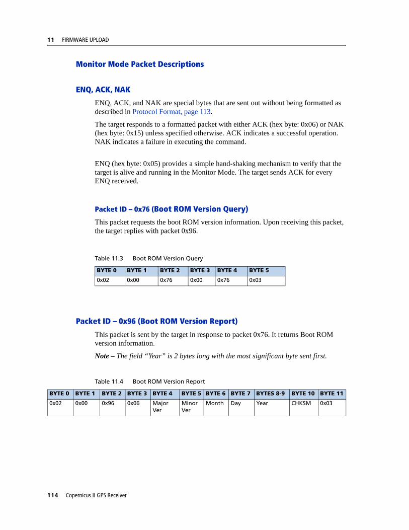
11 FIRMWARE UPLOAD
Monitor Mode Packet Descriptions
ENQ, ACK, NAK
ENQ, ACK, and NAK are special bytes that are sent out without being formatted as described in Protocol Format, page 113.
The target responds to a formatted packet with either ACK (hex byte: 0x06) or NAK (hex byte: 0x15) unless specified otherwise. ACK indicates a successful operation. NAK indicates a failure in executing the command.
ENQ (hex byte: 0x05) provides a simple hand-shaking mechanism to verify that the target is alive and running in the Monitor Mode. The target sends ACK for every ENQ received.
Packet ID – 0x76 (Boot ROM Version Query)
This packet requests the boot ROM version information. Upon receiving this packet, the target replies with packet 0x96.
Packet ID – 0x96 (Boot ROM Version Report)
This packet is sent by the target in response to packet 0x76. It returns Boot ROM version information.
Note – The field “Year” is 2 bytes long with the most significant byte sent first.
Table 11.3 Boot ROM Version Query
BYTE 0 BYTE 1 BYTE 2 BYTE 3 BYTE 4 BYTE 5
0x02 0x00 0x76 0x00 0x76 0x03
Table 11.4 Boot ROM Version Report
BYTE 0 BYTE 1 BYTE 2 BYTE 3 BYTE 4 BYTE 5 BYTE 6 BYTE 7 BYTES 8-9 BYTE 10 BYTE 11
0x02 0x00 0x96 0x06 Major Ver
Minor Ver
Month Day Year CHKSM 0x03
114 Copernicus II GPS Receiver

FIRMWARE UPLOAD 11
Packet ID – 0x86 (Change Baud Rate)
This packet forces the target system to change the serial baud rate to the specified rate. The valid baud rate values are listed in the table below. The target system returns ACK in the old baud rate before the change and another ACK in the new baud rate if the change succeeds. If the baud rate change fails, the unit returns NAK in the old baud rate.
Packet ID – 0x8F (Erase Firmware Section)
This packet initiates the erase operation on the target. It only erases the firmware portion of the Flash chip. The target returns either ACK or NAK indicating the result of the operation.
Table 11.5 Change Baud Rate
BYTE 0 BYTE 1 BYTE 2 BYTE 3 BYTE 4 BYTE 5 Byte 6
0x02 0x00 0x86 0.01 Baud CHKSM 0x03
Table 11.6 Change Baud Rate
Parameter Data Type Description
Baud Rate Byte Baud Rate:5 – 2400 bps
6 – 4800 bps7 – 9600 bps
8 – 19200 bps9 – 38400 bps10 – 57600 bps
11 – 115200 bps
Table 11.7 Erase Firmware Section
BYTE 0 BYTE 1 BYTE 2 BYTE 3 BYTE 4 BYTE 5
0x02 0x00 0x8F 0x00 0x8F 0x03
Copernicus II GPS Receiver 115

11 FIRMWARE UPLOAD
Packet ID – 0x8B (Start Firmware Programming)
This packet initiates firmware loading. It has two parameters. The first parameter (4-byte value) contains the size of the firmware in bytes. This is the actual number of bytes that will be written to Flash. The second parameter contains the starting address in Flash where the data will be written.
Once the target receives this packet, it will respond with ACK and wait for the actual data, one word at a time. Each word must be sent with the most significant byte first. All data from the host will be written to the target in the order in which it is received. The target will not recognize any other packets until the loading is completed. If successful, the target will return ACK upon completion, or NAK if an error has occurred.
C WARNING – The target does not check validity of the starting address nor the size. It is the host’s responsibility to ensure that all parameters are within the system specification. If incorrect specification of the starting address overwrites Boot Code, the module will be unusable.
Table 11.8 Start Firmware Programming
BYTE 0 BYTE 1 BYTE 2 BYTE 3 BYTES 4-7 BYTES 8-11 BYTE 12 BYTE 13
0x02 0x00 0x8B 0x08 Size Address CHKSM 0x03
Table 11.9 Start Firmware Programming
Parameter Data Type Description
Size unsigned long Size of loadable data in bytes.
Address unsigned long Starting physical address where data will be written to.
116 Copernicus II GPS Receiver

FIRMWARE UPLOAD 11
Packet ID – 0x8C (Restart Target)
This packet returns the target from the monitor to the normal operating mode. As at startup, the target will initialize all system resources and perform all system tests. The target returns ACK to acknowledge the received packet before the execution.
This packet is designed to bring the receiver from the monitor mode to the normal mode after a firmware update.
Note – This packet also clears all BBRAM sections to guarantee a cold start after a firmware update.
Table 11.10 Restart Target
BYTE 0 BYTE 1 BYTE 2 BYTE 3 BYTE 4 BYTE 5
0x02 0x00 0x8C 0x00 0x8C 0x03
Copernicus II GPS Receiver 117

11 FIRMWARE UPLOAD
FlashLoader Tool Reference Guide
Introduction
Flash Loader is a tool for Microsoft Windows that loads firmware into the Flash chip of the GPS receiver. This tool is used to upload new firmware into the Copernicus II GPS receiver mounted on the Reference Board installed in the Copernicus II GPS Starter Kit.
The source code of the tool is documented to provide an example of how to develop a custom application to perform firmware updates. It shows how to use the Monitor protocol to implement the firmware loading procedure (see Firmware Loading Procedure, page 109). It can be used, for example, to develop a program to update firmware remotely over a network connection.
FlashLoader has been created using the Microsoft Visual C++® v6.0 development environment. It uses the MFC framework to implement the graphical user interface. While the compiled executable of the tool is provided together with the source code, Microsoft Visual C++ v6.0 or .NET is required to re-compile the source files and generate a fresh executable if desired.
File and Folder Structure
The FlashLoader tool directory contains the following 3 sub-directories:
• bin – contains the FlashLoader binary executable file;
• mak – contains the project files for Microsoft Visual C++ v6.0 and .NET development environments;
• src – contains the C++ source and header files
Source Code Reference
All source code files referenced in this section are located in the src directory of the FlashLoader tool distribution. The source files are fully commented throughout.
Parsing Firmware BIN File
The function LoadBinFile() defined in Util.cpp shows how to parse the firmware BIN file, extract the loadable data, and store into a local buffer for sending to the target.
Creating Packets in the Monitor Protocol Format
The functions GetXxxxxPkt() defined in Util.cpp show how to format various packets using the monitor interface protocol.
118 Copernicus II GPS Receiver

FIRMWARE UPLOAD 11
Loading Firmware to the Target
The function FlashProgrammingThread() defined in FlashLoaderDlg.cpp shows how to implement the firmware loading procedure described above.
Compiling and Generating the Executable
The FlashLoader tool can be re-compiled using the provided project make files.
If using Microsoft Visual C++ v6.0, open the workspace file FlashLoader.dsw located in the mak directory of the tool distribution. From the main menu, select Build Rebuild All. This will compile the source files, generate the executable, and place it in the bin directory.
If using Microsoft Visual C++ .NET, open the solution file FlashLoader.sln located in the mak directory of the tool distribution. From the main menu, select Build Rebuild Solution. This will compile the source files, generate the executable, and place it in the bin directory.
Copernicus II GPS Receiver 119

11 FIRMWARE UPLOAD
120 Copernicus II GPS Receiver

A P P E N D I X
A
TRIMBLE STANDARD INTERFACE PROTOCOL (TSIP) AIn this appendix:
Interface Scope
Run Mode Packet Structure
Automatic Output Packets
Automatic Position and Velocity Reports
Initialization Packets to Speed Start-up
Packets Output at Power-Up
Timing Packets
Satellite Data Packets
Backwards Compatibility to Lassen iQ
Recommended TSIP Packets
Command Packets Sent to the Receiver
Report Packets Sent by the Receiver to the User
Key Setup Parameters or Packet BB
Packet Descriptions
TSIP Superpackets
Datums
The Trimble Standard Interface Protocol (TSIP) provides the system designer with over 20 commands that may be used to configure a GPS receiver for optimum performance in a variety of applications. TSIP enables the system designer to customize the configuration of a GPS module to meet the requirements of a specific application.
This appendix provides the information needed to make judicious use of the powerful features TSIP has to offer, to greatly enhance overall system performance, and to reduce the total development time. The provided reference tables will help you determine which packets apply to your application. See page 132 for a detailed description of key setup parameters. Application guidelines are provided for each TSIP Command Packet, beginning on page 134.
Copernicus II GPS Receiver 121

A TRIMBLE STANDARD INTERFACE PROTOCOL (TSIP)
Interface ScopeThe Trimble Standard Interface Protocol is used extensively in Trimble receiver designs. The protocol was originally created for the Trimble Advanced Navigation Sensor (TANS) and is colloquially known as the TANS protocol even though the protocol applies to many other devices.
The Copernicus II GPS has two serial I/O communications ports. These are bi-directional control and data ports. The data I/O port characteristics, protocol definitions, and other options are user programmable and can be stored in non-volatile FLASH memory.
The TSIP protocol is based on the transmission of packets of information between the user equipment and the unit. Each packet includes an identification code (1 byte, representing 2 hexadecimal digits) that identifies the meaning and format of the data that follows. Each packet begins and ends with control characters.
This document describes in detail the format of the transmitted data, the packet identification codes, and all available information over the output channel to allow the user to choose the data required for his particular application. As will be discussed, the receiver transmits some of the information (position and velocity solutions, etc.) automatically when it is available, while other information is transmitted only on request. Additional packets may be defined for particular products and these will be covered in the specifications for those products as necessary.
The Copernicus II GPS Monitor included in the Tool Kit is designed to exercise many of the TSIP packets.
Run Mode Packet StructureTSIP packet structure is the same for both commands and reports. The packet format is:
<DLE> <id> <data string bytes> <DLE> <ETX>
Where:
• <DLE> is the byte 0x10
• <ETX> is the byte 0x03
• <id> is a packet identifier byte, which can have any value excepting <ETX> and <DLE>.
The bytes in the data string can have any value. To prevent confusion with the frame sequences <DLE> <ID> and <DLE> <ETX>, every <DLE> byte in the data string is preceded by an extra <DLE> byte ('stuffing'). These extra <DLE> bytes must be added ('stuffed') before sending a packet and removed after receiving the packet. Notice that a simple <DLE> <ETX> sequence does not necessarily signify the end of the packet, as these can be bytes in the middle of a data string. The end of a packet is <ETX> preceded by an odd number of <DLE> bytes.
122 Copernicus II GPS Receiver
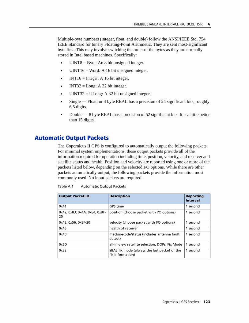
TRIMBLE STANDARD INTERFACE PROTOCOL (TSIP) A
Multiple-byte numbers (integer, float, and double) follow the ANSI/IEEE Std. 754 IEEE Standard for binary Floating-Point Arithmetic. They are sent most-significant byte first. This may involve switching the order of the bytes as they are normally stored in Intel based machines. Specifically:
• UINT8 = Byte: An 8 bit unsigned integer.
• UINT16 = Word: A 16 bit unsigned integer.
• INT16 = Integer: A 16 bit integer.
• INT32 = Long: A 32 bit integer.
• UINT32 = ULong: A 32 bit unsigned integer.
• Single — Float, or 4 byte REAL has a precision of 24 significant bits, roughly 6.5 digits.
• Double — 8 byte REAL has a precision of 52 significant bits. It is a little better than 15 digits.
Automatic Output PacketsThe Copernicus II GPS is configured to automatically output the following packets. For minimal system implementations, these output packets provide all of the information required for operation including time, position, velocity, and receiver and satellite status and health. Position and velocity are reported using one or more of the packets listed below, depending on the selected I/O options. While there are other packets automatically output, the following packets provide the information most commonly used. No input packets are required.
Table A.1 Automatic Output Packets
Output Packet ID Description Reporting Interval
0x41 GPS time 1 second
0x42, 0x83, 0x4A, 0x84, 0x8F-20
position (choose packet with I/O options) 1 second
0x43, 0x56, 0x8F-20 velocity (choose packet with I/O options) 1 second
0x46 health of receiver 1 second
0x4B machinecode/status (includes antenna fault detect)
1 second
0x6D all-in-view satellite selection, DOPs, Fix Mode 1 second
0x82 SBAS fix mode (always the last packet of the fix information)
1 second
Copernicus II GPS Receiver 123

A TRIMBLE STANDARD INTERFACE PROTOCOL (TSIP)
Automatic Position and Velocity ReportsThe receiver automatically outputs position and velocity reports at set intervals. Automatic report packets are controlled by Packet 35. Setting the control bits as indicated in the table below allows you to control which position and velocity packets are output.
Table A.2 Automatic Position and Velocity Reports
Note – In packets 0x42, 0x83, 0x4A, 0x84, 0x43, 0x56, 0x8F-17 and 0x8F-18 when the Time of Fix parameter is reported as -1, this means that the fix information is not calculated by the Copernicus II GPS receiver, but comes from another source such as SRAM, Flash Memory or user input. In Packet 8F-20, this information is denoted by the Invalid Fix parameter: being set to 1 denotes that the fix comes from another source besides the Copernicus II GPS receiver.
Report Packet ID
Request Settings
Packet 0x35, Byte 0 Packet 0x35, Byte 1
Bit 0 Bit 1 Bit 4 Bit 5 Bit 0 Bit 1
0x42 single precision XYZ position
1 0
0x83 double-precision XYZ position
1 1
0x4A single-precision LLA position
1 0
0x84 double-precision LLA position
1 (default)
1
0x43 velocity fix (XYZ, ECEF)
1
0x56 velocity fix (ENU) 1(default)
0x8F-20 LLA and ENU 1
124 Copernicus II GPS Receiver
TRIMBLE STANDARD INTERFACE PROTOCOL (TSIP) A
Notes on Usage of TSIP Packets with UTCMany TSIP messages give the option of outputting the time of fix in UTC time rather than the GPS time. UTC time in these messages is output as a time-of-week, rather than the UTC standard (year / month / day - hour: min: second). There are two instances where conversion from time-of-week to time-of-day may be inaccurate or may require some interpretation.
1. At power-up, there may be no knowledge of the UTC-GPS offset. In this case, the time-of-week will be GPS time. When the UTC-GPS offset is decoded from the GPS broadcast, the user will see a jump backward in time of over 10 seconds. This condition can be detected by looking at the UTC offset data field in the TSIP 0x41 messages, which are automatically output. If the UTC-GPS offset is unknown, the UTC-GPS offset value in the 0x41 will be zero, and the user should anticipate the backward leap in time tag within the first fifteen minutes of clear-view.
2. Every few months a leap second is added, and the UTC-GPS offset increments by one. This is done at the end of the UTC day on 30 June or 31 December. For the remainder of the week, the conversion of the UTC time-of-week to the UTC time-of-day will be off by one second. In most applications, this will be acceptable. If it is critical to maintain correct UTC time, the condition can be detected as follows:
– Query the GPS broadcast message TSIP 0x58-05, which contains the current UTC-GPS offset LS, the future UTC-GPS offset LSF, and the week-number (WNLSF) and day-of-week (DLSF) of the change to LSF.
– If LS does not equal LSF, and the current week number = WNLS, and, the time-of-week is after the end of the day specified by DLS, the UTC time should be adjusted by (LSF - LS)
Copernicus II GPS Receiver 125

A TRIMBLE STANDARD INTERFACE PROTOCOL (TSIP)
Initialization Packets to Speed Start-upIf you are not supplying the receiver with battery power when main power is off, you can still “warm-start” the receiver by sending the following sequence of commands after the receiver has completed its internal initialization and has sent Packet 82. Hot start times can be achieved using packet 0x38-06 to upload the ephemeris. Only time and position are necessary for the hot start since the almanac and ephemeris are stored in flash. Position is also stored in flash which improves first fix accuracy.
Table A.3 Initialization Packets to Speed Start-up
Packets Output at Power-UpThe following table lists the messages output by the receiver at power-up. After completing its self-diagnostics, the receiver automatically outputs a series of packets which indicate the initial operating condition of the receiver. Messages are output as listed in the table below. After Packet 82 is output, the sequence is complete and the receiver is ready to accept commands.
Table A.4 Packets Output at Power-up
Input Byte Description
0x2E Initial Time
0x38 Almanac (for each SV)
0x38 Ephemeris
0x38 Ionosphere Page
0x38 UTC Corrections
0x38 Almanac Health
0x2B Initial Position
Output ID Description Notes
0x45 software version --
0x46 receiver health --
0x4B machine code/status --
As chosen, default: 0x84, 0x56
position/velocity output As chosen, see Table A.2.
0x41 GPS time
0x82 SBAS fix mode See command 0xBB to enable/disable SBAS
126 Copernicus II GPS Receiver

TRIMBLE STANDARD INTERFACE PROTOCOL (TSIP) A
Timing PacketsIf you are using the Copernicus II GPS as a timing reference, you may need to implement the following TSIP control commands.
Table A.5 Timing Packets
Satellite Data PacketsThe following packets contain a variety of GPS satellite data.
Table A.6 Satellite Data Packets
Backwards Compatibility to Lassen iQThe following General Packets and Differences between TSIP Used in Lassen iQ/SQ and Copernicus II GPS receiver:
• 0x41, 0x46, 0x4B automatic packets are output every 1 second instead of every 5 seconds.
• DGPS is not supported in the Copernicus II GPS receiver. Thus, the following packets are not supported:
0x60 /0x61
0x65/0x85
• 0x70 packet is not supported in the Copernicus II GPS receiver. This GPS receiver supports only Kalman Filter and it can not be turned off. A PV filter is not available for the Copernicus II GPS receiver.
• Packet 0xC0 – Graceful Shutdown and Go To Standby Mode is supported in the Copernicus II GPS receiver.
• In “Key Setup Parameters of Packet BB”, BB packet is still the same, but:
Cannot set signal mask.
Fix mode/DOP mask/DOP switch/DGPS correction age are not supported.
The dynamic modes are Land, Sea and Air
Input ID Description Output ID
0x21 get the current GPS time 0x41
0x38-05 request UTC parameters 0x58-05
Input ID Description Output ID
0x27 request signal levels 0x47
0x38 request/load satellite system data 0x58
0x3C request tracking status 0x5C
Copernicus II GPS Receiver 127

A TRIMBLE STANDARD INTERFACE PROTOCOL (TSIP)
• In packet description of 0xBB, Navigation Configuration:
Byte 1, only value 0, automatic is supported
Byte 2, is now used for SBAS
Byte 3, only values 1, 2, and 3 are supported
Bytes 9-12, change AMU mask (not supported)
Bytes 13-21 are changed to reserved.
• In packet 0x1E:
byte 0 - add 0x4D for enter Monitor Mode. The response packet is 0x5F-FF-‘*’-‘*’-‘*’-‘ ‘-‘M’-‘O’-‘N’-‘I’-‘T’-‘O’-‘R’-‘ ‘-‘*’-‘*’-‘*’.
• 0x35/0x55 packets – “Filtered PR’s in 5A” is not supported.
• 0x3A/0x5A packets, Raw Measurement diagnostic packets have been added to the Copernicus II GPS receiver.
• 0x45 packet, Byte 9, “Year number minus 1900” instead of “Year number minus 2000.
• In the 0x7A packet of the Copernicus II GPS receiver, the NMEA sentences TF and BA have been added.
• 0xBC, Protocol Configuration:
Byte 1, Two new baud rates have been added: value 10 (57600 baud), and value 11 (115200 baud)
Byte 3, only value 3 (8 data bits) is supported.
Byte 4, only value 0 (No Parity) is supported.
Byte 5, only value 0 (1 Stop Bit) is supported.
• 8E-4A, PPS Configuration:
Byte 3, Polarity, BYTE, 0 = Positive, 1 = Negative
• 0x8E-17/0x8E-18, Set/Request UTM output are supported in Copernicus II GPS receiver.
• The new packet 0x1C has been added to the Copernicus II GPS receiver. Lassen iQ FW v1.16 also supports this packet.
128 Copernicus II GPS Receiver
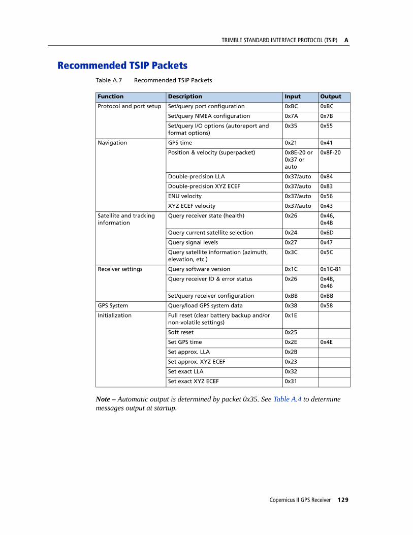
TRIMBLE STANDARD INTERFACE PROTOCOL (TSIP) A
Recommended TSIP PacketsTable A.7 Recommended TSIP Packets
Note – Automatic output is determined by packet 0x35. See Table A.4 to determine messages output at startup.
Function Description Input Output
Protocol and port setup Set/query port configuration 0xBC 0xBC
Set/query NMEA configuration 0x7A 0x7B
Set/query I/O options (autoreport and format options)
0x35 0x55
Navigation GPS time 0x21 0x41
Position & velocity (superpacket) 0x8E-20 or 0x37 or auto
0x8F-20
Double-precision LLA 0x37/auto 0x84
Double-precision XYZ ECEF 0x37/auto 0x83
ENU velocity 0x37/auto 0x56
XYZ ECEF velocity 0x37/auto 0x43
Satellite and tracking information
Query receiver state (health) 0x26 0x46, 0x4B
Query current satellite selection 0x24 0x6D
Query signal levels 0x27 0x47
Query satellite information (azimuth, elevation, etc.)
0x3C 0x5C
Receiver settings Query software version 0x1C 0x1C-81
Query receiver ID & error status 0x26 0x4B, 0x46
Set/query receiver configuration 0xBB 0xBB
GPS System Query/load GPS system data 0x38 0x58
Initialization Full reset (clear battery backup and/or non-volatile settings)
0x1E
Soft reset 0x25
Set GPS time 0x2E 0x4E
Set approx. LLA 0x2B
Set approx. XYZ ECEF 0x23
Set exact LLA 0x32
Set exact XYZ ECEF 0x31
Copernicus II GPS Receiver 129

A TRIMBLE STANDARD INTERFACE PROTOCOL (TSIP)
Command Packets Sent to the ReceiverThe table below summarizes the command packets sent to the receiver. The table includes the input Packet ID, a short description of each packet, and the associated response packet. In some cases, the response packets depend on user-selected options. These selections are covered in the packet descriptions beginning on page 134
Table A.8 Command Packets Sent to the Receiver
Note – Automatic output is determined by packet 0x35. See Table A.4 to determine which messages are output at power-up. No response sent if data is not available.
Input ID Packet Description Output ID
0x1C Hardware and firmware versions numbers 0x1C-81
0x1E Clear battery back-up/reset
0x1F Software version 0x45
0x21 Current time 0x41
0x23 Initial position (XYZ ECEF) --
0x24 Request receiver position fix mode 0x6D
0x25 Soft reset & self-test
0x26 Receiver health 0x46, 0x4B
0x27 Signal levels 0x47
0x2B Initial position (LLA) --
0x2D Oscillator offset 0x4D
0x2E Set GPS time 0x4E
0x31 Accurate initial position (XYZ ECEF) --
0x32 Accurate initial position --
0x35 I/O options 0x55
0x37 Status and values of last position and velocity 0x57
0x38 Load or request satellite system data 0x58
0x3C Tracking status 0x5C
0x69 Receiver acquisition sensitivity mode 0x89
0x7A Set/request NMEA output configuration 0x7B
0x8E-20 Last fix with extra information (fixed point) 0x8F-20
0X8E-21 Request accuracy information 0x8F-21
0x8E-23 Request last compact fix information 0x8F-23
0x8E-26 Store settings in Flash memory. 0x8F-26
0x8E-4A Set Copernicus II GPS Cable Delay and PPS Polarity 0x8F-4A
0xBB Set receiver configuration 0xBB
0xBC Set port configuration 0xBC
0xC0 Go to BBRAM backup state and/or store BBRAM to flash
0xC2 SBAS SV Mask 0xC2
130 Copernicus II GPS Receiver
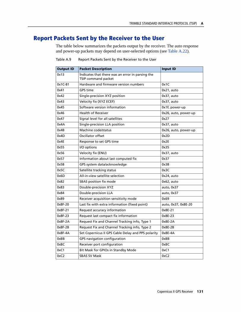
TRIMBLE STANDARD INTERFACE PROTOCOL (TSIP) A
Report Packets Sent by the Receiver to the UserThe table below summarizes the packets output by the receiver. The auto response and power-up packets may depend on user-selected options (see Table A.22).
Table A.9 Report Packets Sent by the Receiver to the User
Output ID Packet Description Input ID
0x13 Indicates that there was an error in parsing the TSIP command packet
0x1C-81 Hardware and firmware version numbers 0x1C
0x41 GPS time 0x21, auto
0x42 Single-precision XYZ position 0x37, auto
0x43 Velocity fix (XYZ ECEF) 0x37, auto
0x45 Software version information 0x1F, power-up
0x46 Health of Receiver 0x26, auto, power-up
0x47 Signal level for all satellites 0x27
0x4A Single-precision LLA position 0x37, auto
0x4B Machine code/status 0x26, auto, power-up
0x4D Oscillator offset 0x2D
0x4E Response to set GPS time 0x2E
0x55 I/O options 0x35
0x56 Velocity fix (ENU) 0x37, auto
0x57 Information about last computed fix 0x37
0x58 GPS system data/acknowledge 0x38
0x5C Satellite tracking status 0x3C
0x6D All-in-view satellite selection 0x24, auto
0x82 SBAS position fix mode 0x62, auto
0x83 Double-precision XYZ auto, 0x37
0x84 Double-precision LLA auto, 0x37
0x89 Receiver acquisition sensitivity mode 0x69
0x8F-20 Last fix with extra information (fixed point) auto, 0x37, 0x8E-20
0x8F-21 Request accuracy information 0x8E-21
0x8F-23 Request last compact fix information 0x8E-23
0x8F-2A Request Fix and Channel Tracking info, Type 1 0x8E-2A
0x8F-2B Request Fix and Channel Tracking info, Type 2 0x8E-2B
0x8F-4A Set Copernicus II GPS Cable Delay and PPS polarity 0x8E-4A
0xBB GPS navigation configuration 0xBB
0xBC Receiver port configuration 0xBC
0xC1 Bit Mask for GPIOs in Standby Mode 0xC1
0xC2 SBAS SV Mask 0xC2
Copernicus II GPS Receiver 131

A TRIMBLE STANDARD INTERFACE PROTOCOL (TSIP)
Key Setup Parameters or Packet BBSelecting the correct operating parameters has significant impact on receiver performance. Packet 0xBB (set receiver configuration) controls the key setup parameters.
The default operating parameters allow the receiver to perform well in almost any environment. The user can optimize the receiver to a particular application if the vehicle dynamics and expected level of obscuration are understood. If the receiver is then taken out of this environment, the specifically tuned receiver may not operate as well as a receiver with the default options
Table A.10 Key Setup Parameters or Packet BB.
The default values in Table A.10 allow the receiver to operate well under the most varied and demanding conditions. A user may choose to change the default parameters if the receiver is only required to perform in a specific or limited environment. The user should be warned that when the receiver is exposed to operating conditions which are different from the conditions described by the user setup, then the performance may be degraded.
Initially, the user must consider the environment in which the receiver is expected to operate. There is a trade-off between how frequently a position fix is output versus the absolute accuracy of the fix. The user must decide which takes priority and then make the appropriate selections. This becomes increasingly important when frequent satellite blockages are expected, as in downtown “urban canyon” environments and heavily foliated areas.
Following is a description of the key fields in Packet 0xBB.
Parameter Factory Default
Dynamics code Land
Elevation mask 5°
SBAS on/off WAAS_Auto
132 Copernicus II GPS Receiver
TRIMBLE STANDARD INTERFACE PROTOCOL (TSIP) A
Dynamics Code
The feature default is LAND mode, where the receiver assumes a moderate dynamic environment. In this case, the satellite search and re-acquisition routines are optimized for vehicle type environments. In SEA mode, the search and re-acquisition routines assume a low acceleration environment. In AIR mode, the search and re-acquisition routines are optimized for high acceleration conditions.
There are a number of operational sanity limits in the Copernicus II GPS that when exceeded the receiver will cease data output until the device is back within operational range.
• Dynamics modeLand: Altitude [-2000 m, 9000 m] Speed < 120 m/s Acceleration < 10 m/s^2
• Dynamics modeSea: Altitude [-2000 m, 9000 m] Speed < 45 m/s Acceleration < 10 m/s^2
• Dynamics modeAir: Altitude [-2000 m, 50000 m] Speed < 515 m/s Acceleration < 40 m/s^2
Elevation Mask
This is the minimum elevation angle for satellites to be used in a solution output by the receiver. Satellites which are near the horizon are typically more difficult to track due to signal attenuation, and are also generally less accurate due to higher variability in the ionospheric and tropospheric corruption of the signal. When there are no obstructions, the receiver can generally track a satellite down to near the horizon.
The benefit of a low elevation mask is that more satellites are available for use in a solution resulting in a better PDOP. The current mask is set to five degrees and provides a reasonable trade-off of the benefits and drawbacks. High accuracy users may prefer a mask angle around ten degrees, where the ionosphere and troposphere begin to be more predictable
Copernicus II GPS Receiver 133

A TRIMBLE STANDARD INTERFACE PROTOCOL (TSIP)
Packet Descriptions
Packet Descriptions Used in Run Mode
Command Packet 0x1C - Firmware Version 01
The command packet 0x1C: 01 may be issued to obtain the firmware version. The product name is “Copernicus II GPS Receiver”. The packet format is defined in the following table.
Table A.11 Command Packet 0x1C
Table A.12 Report Packet 0x1C: 81
Byte Item Type Value Definition
0 Packet ID U8 0x1C Packet ID 0x1C
1 Sub-code U8 0x01 Sub-code 0x01 for software component version information request
Byte Item Type Value Definition
0 Packet ID U8 0x1C Packet ID 0x1C
1 Sub-code U8 0x81 Sub-code 0x81 for software component version information report
2 Reserved U8 Any Reserved
3 Major version U8 Any Firmware major version
4 Minor version U8 Any Firmware minor version
5 Build number U8 Any Firmware build number
6 Month U8 1-12 Firmware build month
7 Day U8 1-31 Firmware build Day
8…9 Year U16 Any Firmware build Year
10 Length of first module name
U8 Any The length of the product name (L1)
11… (10+L1) Product name U8 String Product name in ASCII
134 Copernicus II GPS Receiver

TRIMBLE STANDARD INTERFACE PROTOCOL (TSIP) A
Command Packet 0x1C: 03 - Hardware Component Version Information
• The command packet 0x1C: 03 may be issued to obtain the hardware component version information.
• The report packet is of variable length, depending on the length of the hardware ID.
• The serial number, build date fields, and the hardware ID are programmed into the Copernicus II GPS at production.
• The hardware code for Copernicus II GPS Receiver is 1002.
• ID for Copernicus II GPS Receiver is COPERNICUS II GPS RECEIVER.
The packet format is defined below.
Table A.13 Command Packet 0x1C:03
Report Packet 0x1C: 83 - Hardware Component Version Information
Table A.14 Report Packet 0x1C:83
Byte Item Type Value Definition
0 Packet ID U8 0x1C Packet ID 0x1C
1 Sub-code U8 0x03 Sub-code 0x03 for hardware component version information request
Byte Item Type Value Definition
0 Packet ID U8 0x1C Packet ID 0x1C
1 Sub-code U8 0x83 Sub-code 0x83 for hardware component version information report
2…5 Serial number
U32 Any Board serial number
6 Build day U8 1-31 Day of the board's build date
7 Build month
U8 1-12 Month of the board's build date
8…9 Build year U16 Any Year of the board's build date
10 Build hour U8 0-23 Hour of the board's build date
11…12 Hardware Code
U16 Any Hardware Code associated with Hardware ID
13 Length of Hardware ID
U8 Any The length of the Hardware ID (L)
14... (13+L) Hardware ID
U8 String Hardware ID string in ASCII
Copernicus II GPS Receiver 135
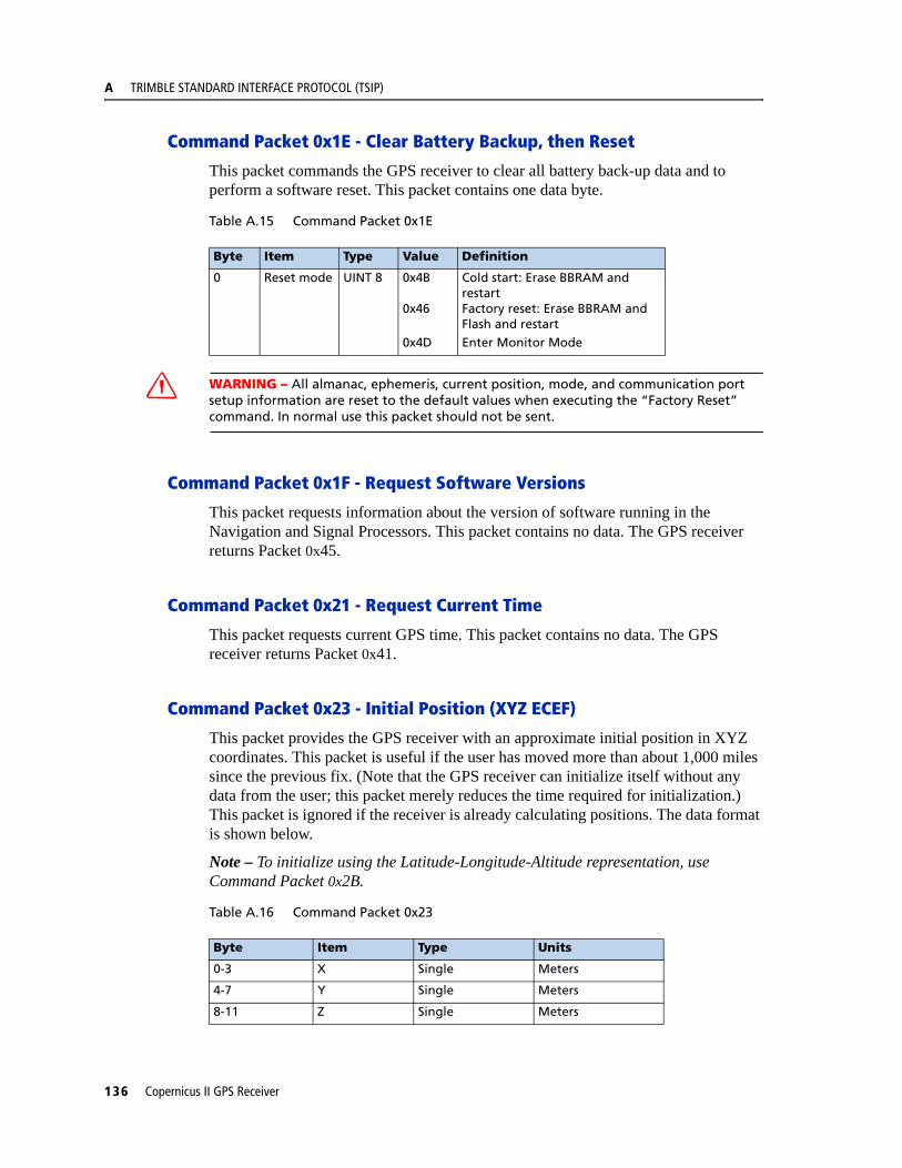
A TRIMBLE STANDARD INTERFACE PROTOCOL (TSIP)
Command Packet 0x1E - Clear Battery Backup, then Reset
This packet commands the GPS receiver to clear all battery back-up data and to perform a software reset. This packet contains one data byte.
Table A.15 Command Packet 0x1E
C WARNING – All almanac, ephemeris, current position, mode, and communication port setup information are reset to the default values when executing the “Factory Reset” command. In normal use this packet should not be sent.
Command Packet 0x1F - Request Software Versions
This packet requests information about the version of software running in the Navigation and Signal Processors. This packet contains no data. The GPS receiver returns Packet 0x45.
Command Packet 0x21 - Request Current Time
This packet requests current GPS time. This packet contains no data. The GPS receiver returns Packet 0x41.
Command Packet 0x23 - Initial Position (XYZ ECEF)
This packet provides the GPS receiver with an approximate initial position in XYZ coordinates. This packet is useful if the user has moved more than about 1,000 miles since the previous fix. (Note that the GPS receiver can initialize itself without any data from the user; this packet merely reduces the time required for initialization.) This packet is ignored if the receiver is already calculating positions. The data format is shown below.
Note – To initialize using the Latitude-Longitude-Altitude representation, use Command Packet 0x2B.
Table A.16 Command Packet 0x23
Byte Item Type Value Definition
0 Reset mode UINT 8 0x4B
0x46
0x4D
Cold start: Erase BBRAM and restartFactory reset: Erase BBRAM and Flash and restartEnter Monitor Mode
Byte Item Type Units
0-3 X Single Meters
4-7 Y Single Meters
8-11 Z Single Meters
136 Copernicus II GPS Receiver

TRIMBLE STANDARD INTERFACE PROTOCOL (TSIP) A
Command Packet 0x24 - Request GPS Receiver Position Fix Mode
This packet requests current position fix mode of the GPS receiver. This packet contains no data. The GPS receiver returns Packet 0x6D.
Command Packet 0x25 - Initiate Soft Reset & Self Test
This packet commands the GPS receiver to perform a software reset. The GPS receiver performs a self-test as part of the reset operation. This packet contains no data. Following completion of the reset, the receiver will output the start-up messages (see Table A.4). The GPS receiver sends Packet 0x45 only on power-up and reset (or on request); thus if Packet 0x45 appears unrequested, then either the GPS receiver power was cycled or the GPS receiver was reset.
Command Packet 0x26 - Request Health
This packet requests health and status information from the GPS receiver. This packet contains no data. The GPS receiver returns Packet 0x46 and 0x4B.
Command Packet 0x27 - Request Signal Levels
This packet requests signal levels for all satellites currently being tracked. This packet contains no data. The GPS receiver returns Packet 0x47.
Command Packet 0x2B - Initial Position (Latitude, Longitude, Altitude)
This packet provides the GPS receiver with an approximate initial position in latitude and longitude coordinates (WGS-84). This packet is useful if the user has moved more than about 1,000 miles since the previous fix. (Note that the GPS receiver can initialize itself without any data from the user; this packet merely reduces the time required for initialization.) This packet is ignored if the receiver is already calculating positions. The data format is shown in the table below.
Note – To initialize with ECEF position, use Command Packet 0x23.
Table A.17 Command Packet 0x2B
Byte Item Type Units
0-3 Latitude Single Radians, north
4-7 Longitude Single Radians, east
8-11 Altitude Single Meters
Copernicus II GPS Receiver 137

A TRIMBLE STANDARD INTERFACE PROTOCOL (TSIP)
Command Packet 0x2D - Request Oscillator Offset
This packet requests the calculated offset of the GPS receiver master oscillator. This packet contains no data. The GPS receiver returns Packet 0x4D. This packet is used mainly for service. The permissible oscillator offset varies with the particular GPS receiver unit.
Command Packet 0x2E - Set GPS Time
This packet provides the approximate GPS time of week and the week number to the GPS receiver. The GPS receiver returns Packet 0x4E. The data format is shown below. The GPS week number reference is Week # 0 starting January 6, 1980. The seconds count begins at the midnight which begins each Sunday morning. This packet is usually not required when the battery back-up voltage is applied as the internal clock keeps time to sufficient accuracy. This packet is ignored if the receiver has already calculated the time from tracking a GPS satellite.
Note – See report Packet 41 for information on the Extended GPS week number.
Command Packet 0x31 - Accurate Initial Position (XYZ ECEF)
This packet is identical in content to Packet 0x23. This packet provides an initial position to the GPS receiver in XYZ coordinates. However, the GPS receiver assumes the position provided in this packet to be accurate. This packet is used for satellite acquisition aiding in systems where another source of position is available. For acquisition aiding, the position provided by the user to the GPS receiver in this packet should be accurate to a few kilometers. For high-accuracy time transfer, position should be accurate to a few meters.
Table A.18 Command Packet 0x2E
Byte Item Type Units
0-3 GPS time of week Single Seconds
4-5 Extended GPS week number INT16 Weeks
Table A.19 Command Packet 0x31
Byte Item Type Units
0-3 X-axis Single Meters
4-7 Y-axis Single Meters
8-11 Z-axis Single Meters
138 Copernicus II GPS Receiver
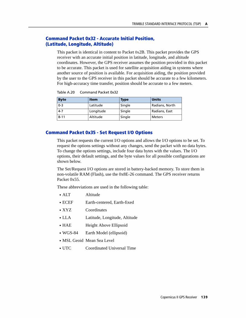
TRIMBLE STANDARD INTERFACE PROTOCOL (TSIP) A
Command Packet 0x32 - Accurate Initial Position, (Latitude, Longitude, Altitude)
This packet is identical in content to Packet 0x2B. This packet provides the GPS receiver with an accurate initial position in latitude, longitude, and altitude coordinates. However, the GPS receiver assumes the position provided in this packet to be accurate. This packet is used for satellite acquisition aiding in systems where another source of position is available. For acquisition aiding, the position provided by the user to the GPS receiver in this packet should be accurate to a few kilometers. For high-accuracy time transfer, position should be accurate to a few meters.
Command Packet 0x35 - Set Request I/O Options
This packet requests the current I/O options and allows the I/O options to be set. To request the options settings without any changes, send the packet with no data bytes. To change the options settings, include four data bytes with the values. The I/O options, their default settings, and the byte values for all possible configurations are shown below.
The Set/Request I/O options are stored in battery-backed memory. To store them in non-volatile RAM (Flash), use the 0x8E-26 command. The GPS receiver returns Packet 0x55.
These abbreviations are used in the following table:
• ALT Altitude
• ECEF Earth-centered, Earth-fixed
• XYZ Coordinates
• LLA Latitude, Longitude, Altitude
• HAE Height Above Ellipsoid
• WGS-84 Earth Model (ellipsoid)
• MSL Geoid Mean Sea Level
• UTC Coordinated Universal Time
Table A.20 Command Packet 0x32
Byte Item Type Units
0-3 Latitude Single Radians, North
4-7 Longitude Single Radians, East
8-11 Altitude Single Meters
Copernicus II GPS Receiver 139

A TRIMBLE STANDARD INTERFACE PROTOCOL (TSIP)
This packet can also be used to set the Automatic output to 1/second for packets 0x47 and 0x5A.
Table A.21 Command Packet 0x35
Byte Bit Item Type Value Definition
Position
0 0 (LSB) XYZ ECEF Bit 0
1
XYZ ECEF output off
XYZ ECEF output on
1 LLA Output Bit 01
LLA output offLLA output on
2 LLA ALT Output
Bit 01
HAE (See Note)MSL geoid
3 Reserved
4 Precision-of- position output
Bit 01
Send single-precision packetSend double-precision packet
5 Super Packet Output
Bit 01
Output no Super PacketsOutput all enabled Super Packets
6-7 Reserved
140 Copernicus II GPS Receiver
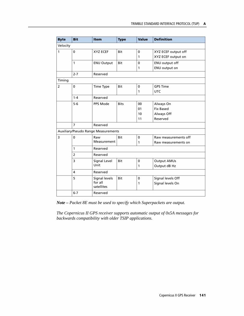
TRIMBLE STANDARD INTERFACE PROTOCOL (TSIP) A
Note – Packet 8E must be used to specify which Superpackets are output.
The Copernicus II GPS receiver supports automatic output of 0x5A messages for backwards compatibility with older TSIP applications.
Velocity
1 0 XYZ ECEF Bit 01
XYZ ECEF output offXYZ ECEF output on
1 ENU Output Bit 01
ENU output offENU output on
2-7 Reserved
Timing
2 0 Time Type Bit 01
GPS TimeUTC
1-4 Reserved
5-6 PPS Mode Bits 0001
1011
Always OnFix Based
Always OffReserved
7 Reserved
Auxiliary/Pseudo Range Measurements
3 0 Raw Measurement
Bit 0
1
Raw measurements off
Raw measurements on
1 Reserved
2 Reserved
3 Signal Level Unit
Bit 01
Output AMUsOutput dB Hz
4 Reserved
5 Signal levels for all satellites
Bit 01
Signal levels OffSignal levels On
6-7 Reserved
Byte Bit Item Type Value Definition
Copernicus II GPS Receiver 141
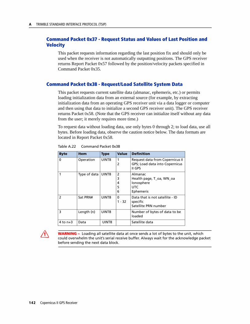
A TRIMBLE STANDARD INTERFACE PROTOCOL (TSIP)
Command Packet 0x37 - Request Status and Values of Last Position and Velocity
This packet requests information regarding the last position fix and should only be used when the receiver is not automatically outputting positions. The GPS receiver returns Report Packet 0x57 followed by the position/velocity packets specified in Command Packet 0x35.
Command Packet 0x38 - Request/Load Satellite System Data
This packet requests current satellite data (almanac, ephemeris, etc.) or permits loading initialization data from an external source (for example, by extracting initialization data from an operating GPS receiver unit via a data logger or computer and then using that data to initialize a second GPS receiver unit). The GPS receiver returns Packet 0x58. (Note that the GPS receiver can initialize itself without any data from the user; it merely requires more time.)
To request data without loading data, use only bytes 0 through 2; to load data, use all bytes. Before loading data, observe the caution notice below. The data formats are located in Report Packet 0x58.
C WARNING – Loading all satellite data at once sends a lot of bytes to the unit, which could overwhelm the unit’s serial receive buffer. Always wait for the acknowledge packet before sending the next data block.
Table A.22 Command Packet 0x38
Byte Item Type Value Definition
0 Operation UINT8 12
Request data from Copernicus II GPS; Load data into Copernicus II GPS
1 Type of data UINT8 23456
AlmanacHealth page, T_oa, WN_oaIonosphereUTCEphemeris
2 Sat PRN# UINT8 01 - 32
Data that is not satellite - ID specificSatellite PRN number
3 Length (n) UINT8 Number of bytes of data to be loaded
4 to n+3 Data UINT8 Satellite data
142 Copernicus II GPS Receiver

TRIMBLE STANDARD INTERFACE PROTOCOL (TSIP) A
Command Packet 0x3A - Request Last Raw Measurement
This packet requests the most recent raw measurement data for one specified satellite. The GPS receiver returns packet 0x5A if data is available.
.
Command Packet 0x3C - Request Current Satellite Tracking Status
This packet requests the current satellite tracking status. The GPS receiver returns Packet 0x5C if data is available.
Report Packet 0x41 - GPS Time
This packet provides the current GPS time of week and the week number. The GPS receiver sends this packet in response to Packet 0x21 and during an automatic packets update cycle. The data format is shown below.
Note – UTC time lags behind GPS time by an integer number of seconds; UTC = (GPS time) - (GPS UTC offset).
C WARNING – GPS week number runs from 0 to 1023 and then cycles back to week #0. week # 0 began January 6, 1980. The first cycle back to week #0 was on August 22, 1999. The extended GPS week number however, does not cycle back to 0. For example: the week # for August 22, 1999 = 1024; the Week # for April 1, 2002 = 1160.
Table A.23 Command Packet 0x3C
Byte Item Type Value Definition
0 Satellite # UINT8 0
1 - 32
All satellites in the current track set.
Desired satellite.
Table A.24 Command Packet 0x3C
Byte Item Type Value Definition
0 Satellite # UINT8 0
1 - 138
All satellites in the current track set.Desired satellite.
Table A.25 Report Packet 0x41
Byte Item Type Units
0-3 GPS time of week Single seconds
4-5 Extended GPS week number INT16 weeks
6-9 GPS UTC offset Single seconds
Copernicus II GPS Receiver 143
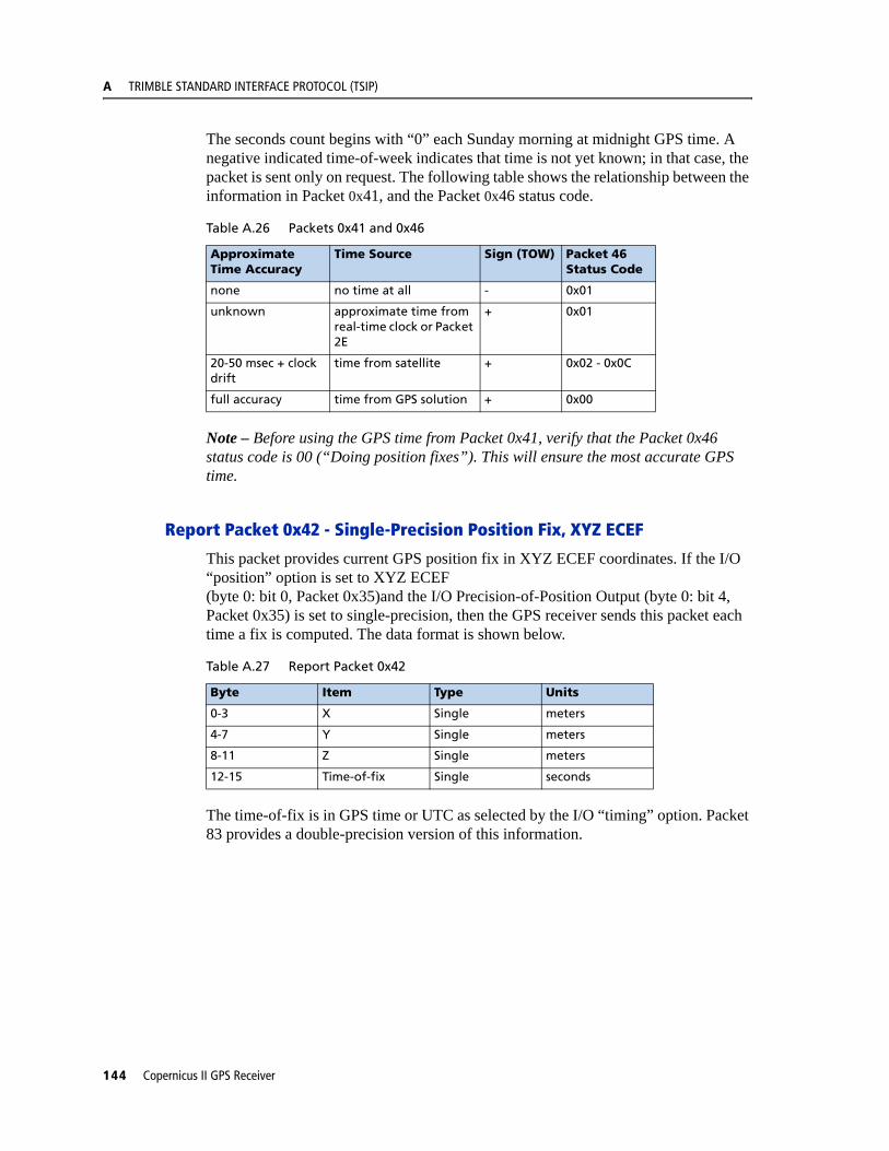
A TRIMBLE STANDARD INTERFACE PROTOCOL (TSIP)
The seconds count begins with “0” each Sunday morning at midnight GPS time. A negative indicated time-of-week indicates that time is not yet known; in that case, the packet is sent only on request. The following table shows the relationship between the information in Packet 0x41, and the Packet 0x46 status code.
Note – Before using the GPS time from Packet 0x41, verify that the Packet 0x46 status code is 00 (“Doing position fixes”). This will ensure the most accurate GPS time.
Report Packet 0x42 - Single-Precision Position Fix, XYZ ECEF
This packet provides current GPS position fix in XYZ ECEF coordinates. If the I/O “position” option is set to XYZ ECEF (byte 0: bit 0, Packet 0x35)and the I/O Precision-of-Position Output (byte 0: bit 4, Packet 0x35) is set to single-precision, then the GPS receiver sends this packet each time a fix is computed. The data format is shown below.
The time-of-fix is in GPS time or UTC as selected by the I/O “timing” option. Packet 83 provides a double-precision version of this information.
Table A.26 Packets 0x41 and 0x46
Approximate Time Accuracy
Time Source Sign (TOW) Packet 46Status Code
none no time at all - 0x01
unknown approximate time from real-time clock or Packet 2E
+ 0x01
20-50 msec + clock drift
time from satellite + 0x02 - 0x0C
full accuracy time from GPS solution + 0x00
Table A.27 Report Packet 0x42
Byte Item Type Units
0-3 X Single meters
4-7 Y Single meters
8-11 Z Single meters
12-15 Time-of-fix Single seconds
144 Copernicus II GPS Receiver
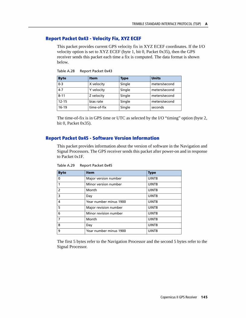
TRIMBLE STANDARD INTERFACE PROTOCOL (TSIP) A
Report Packet 0x43 - Velocity Fix, XYZ ECEF
This packet provides current GPS velocity fix in XYZ ECEF coordinates. If the I/O velocity option is set to XYZ ECEF (byte 1, bit 0, Packet 0x35), then the GPS receiver sends this packet each time a fix is computed. The data format is shown below.
The time-of-fix is in GPS time or UTC as selected by the I/O “timing” option (byte 2, bit 0, Packet 0x35).
Report Packet 0x45 - Software Version Information
This packet provides information about the version of software in the Navigation and Signal Processors. The GPS receiver sends this packet after power-on and in response to Packet 0x1F.
The first 5 bytes refer to the Navigation Processor and the second 5 bytes refer to the Signal Processor.
Table A.28 Report Packet 0x43
Byte Item Type Units
0-3 X velocity Single meters/second
4-7 Y velocity Single meters/second
8-11 Z velocity Single meters/second
12-15 bias rate Single meters/second
16-19 time-of-fix Single seconds
Table A.29 Report Packet 0x45
Byte Item Type
0 Major version number UINT8
1 Minor version number UINT8
2 Month UINT8
3 Day UINT8
4 Year number minus 1900 UINT8
5 Major revision number UINT8
6 Minor revision number UINT8
7 Month UINT8
8 Day UINT8
9 Year number minus 1900 UINT8
Copernicus II GPS Receiver 145
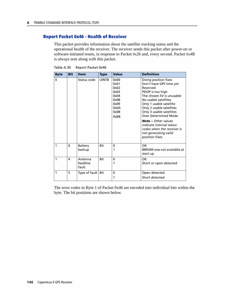
A TRIMBLE STANDARD INTERFACE PROTOCOL (TSIP)
Report Packet 0x46 - Health of Receiver
This packet provides information about the satellite tracking status and the operational health of the receiver. The receiver sends this packet after power-on or software-initiated resets, in response to Packet 0x26 and, every second. Packet 0x4B is always sent along with this packet.
The error codes in Byte 1 of Packet 0x46 are encoded into individual bits within the byte. The bit positions are shown below.
Table A.30 Report Packet 0x46
Byte Bit Item Type Value Definition
0 Status code UINT8 0x000x010x020x030x040x080x090x0A0x0B0xBB
Doing position fixesDon't have GPS time yetReservedPDOP is too highThe chosen SV is unusableNo usable satellitesOnly 1 usable satelliteOnly 2 usable satellitesOnly 3 usable satellitesOver Determined Mode
Note – Other values indicate internal status codes when the receiver is not generating valid position fixes.
1 0 Battery backup
Bit 01
OKBBRAM was not available at start-up
1 4 Antenna feedline fault
Bit 01
OKShort or open detected
1 5 Type of fault Bit 01
Open detectedShort detected
146 Copernicus II GPS Receiver

TRIMBLE STANDARD INTERFACE PROTOCOL (TSIP) A
Report Packet 0x47 - Signal Levels for all Satellites
This packet provides received signal levels for all satellites currently being tracked or on which tracking is being attempted (i.e., above the elevation mask and healthy according to the almanac). The receiver sends this packet only in response to Packet 0x27. The data format is shown below.
Up to 12 satellite number/signal level pairs may be sent, indicated by the count field. Signal level is normally positive. If it is zero then that satellite has not yet been acquired. If it is negative then that satellite is not currently in lock. The absolute value of signal level field is the last known signal level of that satellite.
Note – The signal level provided in this packet is a linear measurement of the signal strength after correlation or de-spreading. Units, either AMU or dBHz, are controlled by Packet 0x35.
Table A.31 Report Packet 0x47
Byte Item Type
0 Count UINT8
1 Satellite number 1 UINT8
2- 5 Signal level 1 Single
6 Satellite number 2 UINT8
7-10 Signal level 2 Single
(etc.) (etc.) (etc.)
Copernicus II GPS Receiver 147
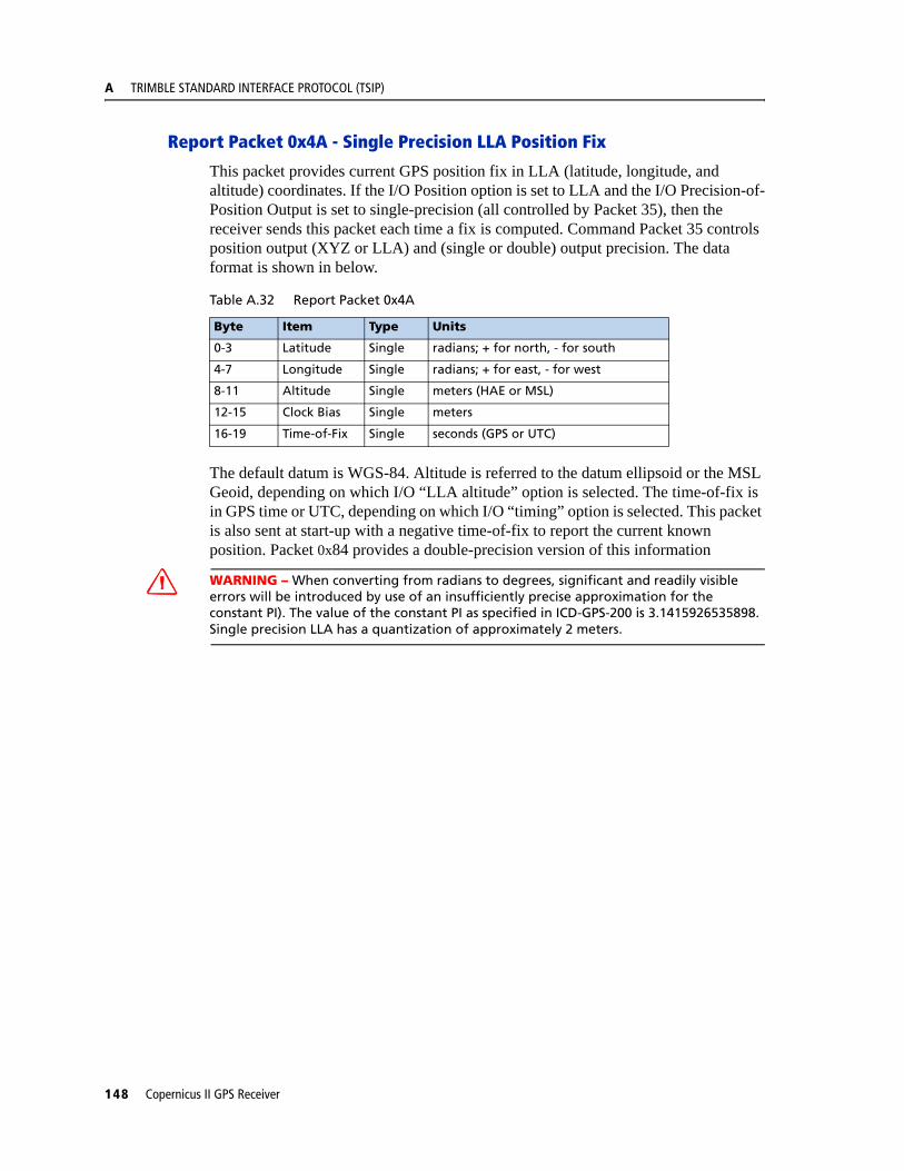
A TRIMBLE STANDARD INTERFACE PROTOCOL (TSIP)
Report Packet 0x4A - Single Precision LLA Position Fix
This packet provides current GPS position fix in LLA (latitude, longitude, and altitude) coordinates. If the I/O Position option is set to LLA and the I/O Precision-of-Position Output is set to single-precision (all controlled by Packet 35), then the receiver sends this packet each time a fix is computed. Command Packet 35 controls position output (XYZ or LLA) and (single or double) output precision. The data format is shown in below.
The default datum is WGS-84. Altitude is referred to the datum ellipsoid or the MSL Geoid, depending on which I/O “LLA altitude” option is selected. The time-of-fix is in GPS time or UTC, depending on which I/O “timing” option is selected. This packet is also sent at start-up with a negative time-of-fix to report the current known position. Packet 0x84 provides a double-precision version of this information
C WARNING – When converting from radians to degrees, significant and readily visible errors will be introduced by use of an insufficiently precise approximation for the constant PI). The value of the constant PI as specified in ICD-GPS-200 is 3.1415926535898. Single precision LLA has a quantization of approximately 2 meters.
Table A.32 Report Packet 0x4A
Byte Item Type Units
0-3 Latitude Single radians; + for north, - for south
4-7 Longitude Single radians; + for east, - for west
8-11 Altitude Single meters (HAE or MSL)
12-15 Clock Bias Single meters
16-19 Time-of-Fix Single seconds (GPS or UTC)
148 Copernicus II GPS Receiver

TRIMBLE STANDARD INTERFACE PROTOCOL (TSIP) A
Report Packet 0x4B - Machine/Code ID and Additional Status
The receiver transmits this packet in response to packets 0x25 and 0x26 and following a change in state. In conjunction with Packet 0x46, “health of receiver,” this packet identifies the receiver and may present status messages. The machine ID can be used by equipment communicating with the receiver to determine the type of receiver to which the equipment is connected. Then the interpretation and use of packets can be adjusted accordingly.
The status codes are encoded into individual bits within the bytes. The bit positions and their meanings are listed in the table below.
Report Packet 0x4D - Oscillator Offset
This packet provides the current value of the receiver master oscillator offset in Hertz at carrier. This packet contains one single precision number. The receiver sends this packet in response to Packet 0x2D. The permissible offset varies with the receiver unit.
Table A.33 Report Packet 0x4B
Byte Item Type/ Definition
0 Machine ID UINT8 96
1 Status 1 UINT8 See Table A.1
2 Status 2 UINT8 Bit 0 set = Superpackets supported
Table A.34 Report Packet 0x4B
Status 1 Bit Positions
Meaning if bit value = 1
0 (LSB) Not used
1 Real-time Clock was not available at power-up.
2 Not used
3 The almanac stored in the receiver is not complete and current.
4-7 Not used
Copernicus II GPS Receiver 149
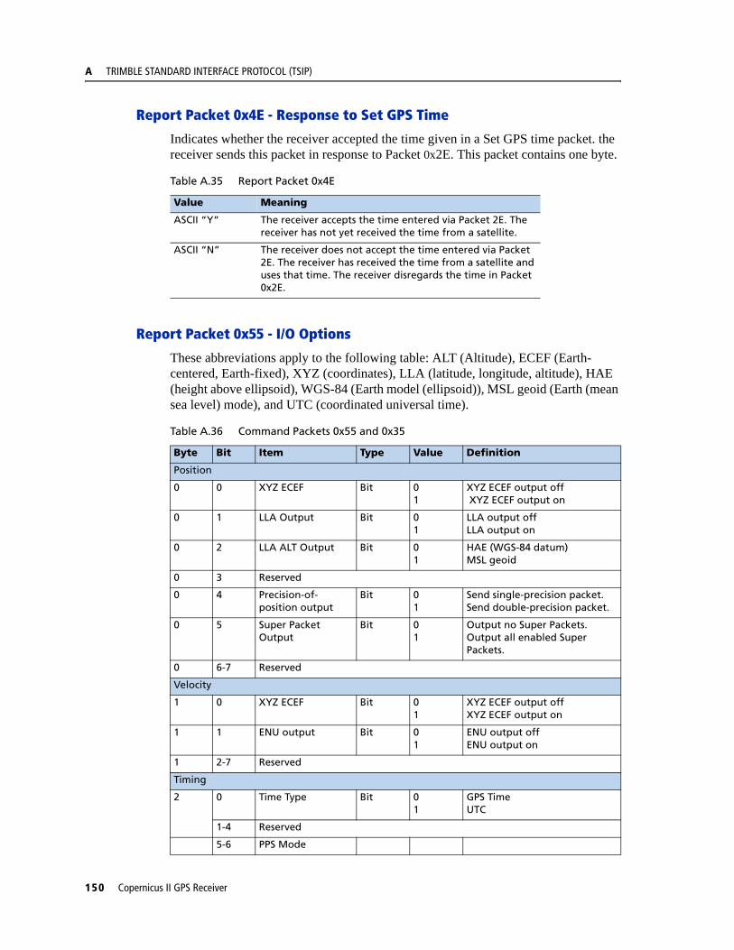
A TRIMBLE STANDARD INTERFACE PROTOCOL (TSIP)
Report Packet 0x4E - Response to Set GPS Time
Indicates whether the receiver accepted the time given in a Set GPS time packet. the receiver sends this packet in response to Packet 0x2E. This packet contains one byte.
Report Packet 0x55 - I/O Options
These abbreviations apply to the following table: ALT (Altitude), ECEF (Earth-centered, Earth-fixed), XYZ (coordinates), LLA (latitude, longitude, altitude), HAE (height above ellipsoid), WGS-84 (Earth model (ellipsoid)), MSL geoid (Earth (mean sea level) mode), and UTC (coordinated universal time).
Table A.35 Report Packet 0x4E
Value Meaning
ASCII “Y” The receiver accepts the time entered via Packet 2E. The receiver has not yet received the time from a satellite.
ASCII “N” The receiver does not accept the time entered via Packet 2E. The receiver has received the time from a satellite and uses that time. The receiver disregards the time in Packet 0x2E.
Table A.36 Command Packets 0x55 and 0x35
Byte Bit Item Type Value Definition
Position
0 0 XYZ ECEF Bit 01
XYZ ECEF output off XYZ ECEF output on
0 1 LLA Output Bit 01
LLA output offLLA output on
0 2 LLA ALT Output Bit 01
HAE (WGS-84 datum)MSL geoid
0 3 Reserved
0 4 Precision-of-position output
Bit 01
Send single-precision packet. Send double-precision packet.
0 5 Super Packet Output
Bit 01
Output no Super Packets.Output all enabled Super Packets.
0 6-7 Reserved
Velocity
1 0 XYZ ECEF Bit 01
XYZ ECEF output offXYZ ECEF output on
1 1 ENU output Bit 01
ENU output offENU output on
1 2-7 Reserved
Timing
2 0 Time Type Bit 01
GPS TimeUTC
1-4 Reserved
5-6 PPS Mode
150 Copernicus II GPS Receiver
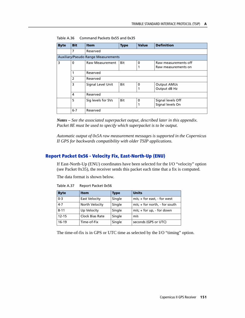
TRIMBLE STANDARD INTERFACE PROTOCOL (TSIP) A
Notes – See the associated superpacket output, described later in this appendix. Packet 8E must be used to specify which superpacket is to be output.
Automatic output of 0x5A raw measurement messages is supported in the Copernicus II GPS for backwards compatibility with older TSIP applications.
Report Packet 0x56 - Velocity Fix, East-North-Up (ENU)
If East-North-Up (ENU) coordinates have been selected for the I/O “velocity” option (see Packet 0x35), the receiver sends this packet each time that a fix is computed.
The data format is shown below.
The time-of-fix is in GPS or UTC time as selected by the I/O “timing” option.
7 Reserved
Auxiliary/Pseudo Range Measurements
3 0 Raw Measurement Bit 01
Raw measurements offRaw measurements on
1 Reserved
2 Reserved
3 Signal Level Unit Bit 01
Output AMUsOutput dB Hz
4 Reserved
5 Sig levels for SVs Bit 01
Signal levels OffSignal levels On
6-7 Reserved
Table A.37 Report Packet 0x56
Byte Item Type Units
0-3 East Velocity Single m/s; + for east, - for west
4-7 North Velocity Single m/s; + for north, - for south
8-11 Up Velocity Single m/s; + for up, - for down
12-15 Clock Bias Rate Single m/s
16-19 Time-of-Fix Single seconds (GPS or UTC)
Table A.36 Command Packets 0x55 and 0x35
Byte Bit Item Type Value Definition
Copernicus II GPS Receiver 151
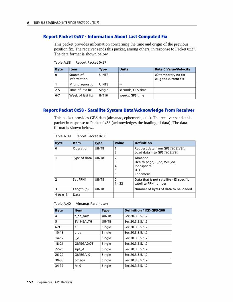
A TRIMBLE STANDARD INTERFACE PROTOCOL (TSIP)
Report Packet 0x57 - Information About Last Computed Fix
This packet provides information concerning the time and origin of the previous position fix. The receiver sends this packet, among others, in response to Packet 0x37. The data format is shown below.
Report Packet 0x58 - Satellite System Data/Acknowledge from Receiver
This packet provides GPS data (almanac, ephemeris, etc.). The receiver sends this packet in response to Packet 0x38 (acknowledges the loading of data). The data format is shown below..
Table A.38 Report Packet 0x57
Byte Item Type Units Byte 0 Value/Velocity
0 Source of information
UINT8 -- 00 temporary no fix01 good current fix
1 Mfg. diagnostic UINT8 --
2-5 Time of last fix Single seconds, GPS time
6-7 Week of last fix INT16 weeks, GPS time
Table A.39 Report Packet 0x58
Byte Item Type Value Definition
0 Operation UINT8 12
Request data from GPS receiver; Load data into GPS receiver
1 Type of data UINT8 23456
AlmanacHealth page, T_oa, WN_oaIonosphereUTCEphemeris
2 Sat PRN# UINT8 01 - 32
Data that is not satellite - ID specific satellite PRN number
3 Length (n) UINT8 Number of bytes of data to be loaded
4 to n+3 Data
Table A.40 Almanac Parameters
Byte Item Type Definition / ICD-GPS-200
4 t_oa_raw UINT8 Sec 20.3.3.5.1.2
5 SV_HEALTH UINT8 Sec 20.3.3.5.1.2
6-9 e Single Sec 20.3.3.5.1.2
10-13 t_oa Single Sec 20.3.3.5.1.2
14-17 i_o Single Sec 20.3.3.5.1.2
18-21 OMEGADOT Single Sec 20.3.3.5.1.2
22-25 sqrt_A Single Sec 20.3.3.5.1.2
26-29 OMEGA_0 Single Sec 20.3.3.5.1.2
30-33 omega Single Sec 20.3.3.5.1.2
34-37 M_0 Single Sec 20.3.3.5.1.2
152 Copernicus II GPS Receiver
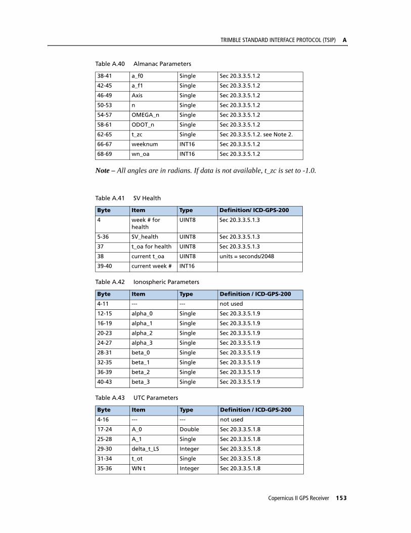
TRIMBLE STANDARD INTERFACE PROTOCOL (TSIP) A
Note – All angles are in radians. If data is not available, t_zc is set to -1.0.
38-41 a_f0 Single Sec 20.3.3.5.1.2
42-45 a_f1 Single Sec 20.3.3.5.1.2
46-49 Axis Single Sec 20.3.3.5.1.2
50-53 n Single Sec 20.3.3.5.1.2
54-57 OMEGA_n Single Sec 20.3.3.5.1.2
58-61 ODOT_n Single Sec 20.3.3.5.1.2
62-65 t_zc Single Sec 20.3.3.5.1.2. see Note 2.
66-67 weeknum INT16 Sec 20.3.3.5.1.2
68-69 wn_oa INT16 Sec 20.3.3.5.1.2
Table A.41 SV Health
Byte Item Type Definition/ ICD-GPS-200
4 week # for health
UINT8 Sec 20.3.3.5.1.3
5-36 SV_health UINT8 Sec 20.3.3.5.1.3
37 t_oa for health UINT8 Sec 20.3.3.5.1.3
38 current t_oa UINT8 units = seconds/2048
39-40 current week # INT16
Table A.42 Ionospheric Parameters
Byte Item Type Definition / ICD-GPS-200
4-11 --- --- not used
12-15 alpha_0 Single Sec 20.3.3.5.1.9
16-19 alpha_1 Single Sec 20.3.3.5.1.9
20-23 alpha_2 Single Sec 20.3.3.5.1.9
24-27 alpha_3 Single Sec 20.3.3.5.1.9
28-31 beta_0 Single Sec 20.3.3.5.1.9
32-35 beta_1 Single Sec 20.3.3.5.1.9
36-39 beta_2 Single Sec 20.3.3.5.1.9
40-43 beta_3 Single Sec 20.3.3.5.1.9
Table A.43 UTC Parameters
Byte Item Type Definition / ICD-GPS-200
4-16 --- --- not used
17-24 A_0 Double Sec 20.3.3.5.1.8
25-28 A_1 Single Sec 20.3.3.5.1.8
29-30 delta_t_LS Integer Sec 20.3.3.5.1.8
31-34 t_ot Single Sec 20.3.3.5.1.8
35-36 WN t Integer Sec 20.3.3.5.1.8
Table A.40 Almanac Parameters
Copernicus II GPS Receiver 153
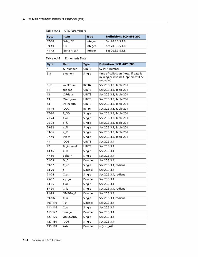
A TRIMBLE STANDARD INTERFACE PROTOCOL (TSIP)
37-38 WN_LSF Integer Sec 20.3.3.5.1.8
39-40 DN Integer Sec 20.3.3.5.1.8
41-42 delta_t_LSF Integer Sec 20.3.3.5.1.8
Table A.44 Ephemeris Data
Byte Item Type Definition / ICD -GPS-200
4 sv_number UINT8 SV PRN number
5-8 t_ephem Single time of collection (note, if data is missing or invalid, t_ephem will be negative)
9-10 weeknum INT16 Sec 20.3.3.3, Table 20-I
11 codeL2 UINT8 Sec 20.3.3.3, Table 20-I
12 L2Pdata UINT8 Sec 20.3.3.3, Table 20-I
13 SVacc_raw UINT8 Sec 20.3.3.3, Table 20-I
14 SV_health UINT8 Sec 20.3.3.3, Table 20-I
15-16 IODC INT16 Sec 20.3.3.3, Table 20-I
17-20 T_GD Single Sec 20.3.3.3, Table 20-I
21-24 t_oc Single Sec 20.3.3.3, Table 20-I
25-28 a_f2 Single Sec 20.3.3.3, Table 20-I
29-32 a_f1 Single Sec 20.3.3.3, Table 20-I
33-36 a_f0 Single Sec 20.3.3.3, Table 20-I
37-40 SVacc Single Sec 20.3.3.3, Table 20-I
41 IODE UINT8 Sec 20.3.3.4
42 fit_interval UINT8 Sec 20.3.3.4
43-46 C_rs Single Sec 20.3.3.4
47-50 delta_n Single Sec 20.3.3.4
51-58 M_0 Double Sec 20.3.3.4
59-62 C_uc Single Sec 20.3.3.4, radians
63-70 e Double Sec 20.3.3.4
71-74 C_us Single Sec 20.3.3.4, radians
75-82 sqrt_A Double Sec 20.3.3.4
83-86 t_oe Single Sec 20.3.3.4
87-90 C_ic Single Sec 20.3.3.4, radians
91-98 OMEGA_0 Double Sec 20.3.3.4
99-102 C_is Single Sec 20.3.3.4, radians
103-110 i_0 Double Sec 20.3.3.4
111-114 C_rc Single Sec 20.3.3.4
115-122 omega Double Sec 20.3.3.4
123-126 OMEGADOT Single Sec 20.3.3.4
127-130 IDOT Single Sec 20.3.3.4
131-138 Axis Double = (sqrt_A)2
Table A.43 UTC Parameters
Byte Item Type Definition / ICD-GPS-200
154 Copernicus II GPS Receiver
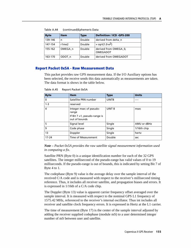
TRIMBLE STANDARD INTERFACE PROTOCOL (TSIP) A
Report Packet 0x5A - Raw Measurement Data
This packet provides raw GPS measurement data. If the I/O Auxiliary options has been selected, the receive sends this data automatically as measurements are taken. The data format is shows in the table below.
Note – Packet 0x5A provides the raw satellite signal measurement information used in computing a fix.
Satellite PRN (Byte 0) is a unique identification number for each of the 32 GPS satellites. The integer millisecond of the pseudo-range has valid values of 0 to 19 milliseconds. If the pseudo-range is out of bounds, this is indicated by setting Bit 7 of Byte 4 to 1.
The codephase (Byte 9) value is the average delay over the sample interval of the received C/A code and is measured with respect to the receiver’s millisecond timing reference. Thus, it includes all receiver satellite, and propagation biases and errors. It is expressed in 1/16th of a C/A code chip.
The Doppler (Byte 13) value is apparent carrier frequency offset averaged over the sample interval. It is measured with respect to the nominal GPS L1 frequency of 1575.42 MHz, referenced to the receiver’s internal oscillator. Thus int includes all receiver and satellite clock frequency errors. It is expressed in Hertz at the L1 carrier.
The time of measurement (Byte 17) is the center of the sample interval adjusted by adding the receiver supplied codephase (module mS) to a user determined integer number of mS between user and satellite.
139-146 n Double derived from delta_n
147-154 r1me2 Double = sqrt(1.0-e2)
155-162 OMEGA_n Double derived from OMEGA_0, OMEGADOT
163-170 ODOT_n Double derived from OMEGADOT
Table A.45 Report Packet 0x5A
Byte Item Type Units
0 Satellite PRN number UINT8 ----
1-3 reserved
4 Integer msec of pseudo-range
If Bit 7 =1, pseudo-range is out of bounds
UINT 8 msec
5 Signal level Single AMU or dBHz
9 Code phase Single 1/16th chip
13 Doppler Single hertz
17-24 Time of Measurement Double sec
Table A.44 (continued)Ephemeris Data
Byte Item Type Definition / ICD -GPS-200
Copernicus II GPS Receiver 155
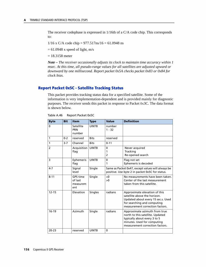
A TRIMBLE STANDARD INTERFACE PROTOCOL (TSIP)
The receiver codephase is expressed in 1/16th of a C/A code chip. This corresponds to:
1/16 x C/A code chip = 977.517ns/16 = 61.0948 ns
= 61.0948 x speed of light, m/s
= 18.3158 meter
Note – The receiver occasionally adjusts its clock to maintain time accuracy within 1 msec. At this time, all pseudo-range values for all satellites are adjusted upward or downward by one millisecond. Report packet 0x5A checks packet 0x83 or 0x84 for clock bias.
Report Packet 0x5C - Satellite Tracking Status
This packet provides tracking status data for a specified satellite. Some of the information is very implementation-dependent and is provided mainly for diagnostic purposes. The receiver sends this packet in response to Packet 0x3C. The data format is shown below.
Table A.46 Report Packet 0x5C
Byte Bit Item Type Value Definition
0 Satellite PRN number
UINT8 number1 - 32
1 0-2 reserved Bits reserved
1 3-7 Channel Bits 0-11
2 Acquisition flag
UINT8 012
Never acquired Tracking Re-opened search
3 Ephemeris flag
UINT8 01
Flag not setEphemeris is decoded
4-7 Signal level
Single Same as Packet 0x47, except values will always be positive. Use byte 2 in packet 0x5C for status.
8-11 GPS time of last measurement
Single <0>0
No measurements have been taken.Center of the last measurement taken from this satellite.
12-15 Elevation Singles radians Approximate elevation of this satellite above the horizon. Updated about every 15 sec.s. Used for searching and computing measurement correction factors.
16-19 Azimuth Single radians Approximate azimuth from true north to this satellite. Updated typically about every 3 to 5 minutes. Used for computing measurement correction factors.
20-23 reserved UINT8 0
156 Copernicus II GPS Receiver
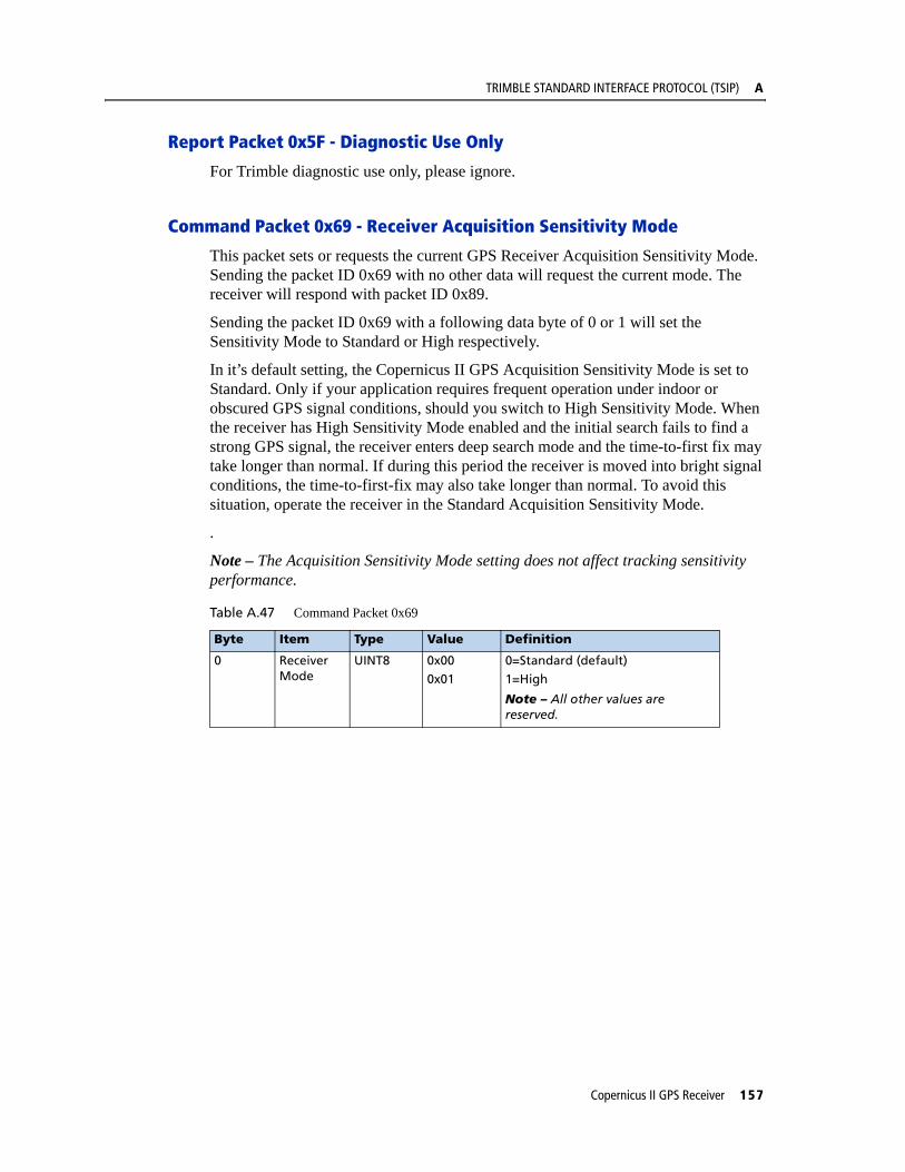
TRIMBLE STANDARD INTERFACE PROTOCOL (TSIP) A
Report Packet 0x5F - Diagnostic Use Only
For Trimble diagnostic use only, please ignore.
Command Packet 0x69 - Receiver Acquisition Sensitivity Mode
This packet sets or requests the current GPS Receiver Acquisition Sensitivity Mode. Sending the packet ID 0x69 with no other data will request the current mode. The receiver will respond with packet ID 0x89.
Sending the packet ID 0x69 with a following data byte of 0 or 1 will set the Sensitivity Mode to Standard or High respectively.
In it’s default setting, the Copernicus II GPS Acquisition Sensitivity Mode is set to Standard. Only if your application requires frequent operation under indoor or obscured GPS signal conditions, should you switch to High Sensitivity Mode. When the receiver has High Sensitivity Mode enabled and the initial search fails to find a strong GPS signal, the receiver enters deep search mode and the time-to-first fix may take longer than normal. If during this period the receiver is moved into bright signal conditions, the time-to-first-fix may also take longer than normal. To avoid this situation, operate the receiver in the Standard Acquisition Sensitivity Mode.
.
Note – The Acquisition Sensitivity Mode setting does not affect tracking sensitivity performance.
Table A.47 Command Packet 0x69
Byte Item Type Value Definition
0 Receiver Mode
UINT8 0x00
0x01
0=Standard (default)
1=High
Note – All other values are reserved.
Copernicus II GPS Receiver 157

A TRIMBLE STANDARD INTERFACE PROTOCOL (TSIP)
Report Packet 0x6D - All-In-View Satellite Selection
This packet provides a list of satellites used for position fixes by the GPS receiver. The packet also provides the PDOP, HDOP, and VDOP of that set and provides the current mode (automatic or manual, 3-D or 2-D). This packet has variable length equal to 16+nSVs where “nSVs” is the number of satellites used in the solution.
When the GPS receiver is in Over-determined Mode, the value for 2-D is displayed. When the GPS receiver is in one of the Navigation Modes, the 2-D flag depends only on the number of satellites used in the last fix (i.e. if the number of satellites is greater than 3 and PDOP is less than 10, then the fix is flagged “3-D”. otherwise it will be “2-D”.)
Note – Fixes with 0, 1, or 2 satellites are marked “2-D” by the above rule.
The GPS receiver sends this packet in response to Packet 0x24. The data format is shown below.
Note – The Copernicus II GPS sends this packet automatically after a position fix or every second if no position fix occurs.
Table A.48 Report Packet 0x6D
Byte Bit Item Type Value Definition
0 0-2 Dimension UINT8 34
2D3D
0 3 01
AutoManual
0 4-7 - nSVs
1-4 PDOP Single PDOP
5-8 HDOP Single HDOP
9-12 VDOP Single VDOP
13-16 TDOP Single TDOP
(16+nSVvs) SV PRN UINT8
158 Copernicus II GPS Receiver
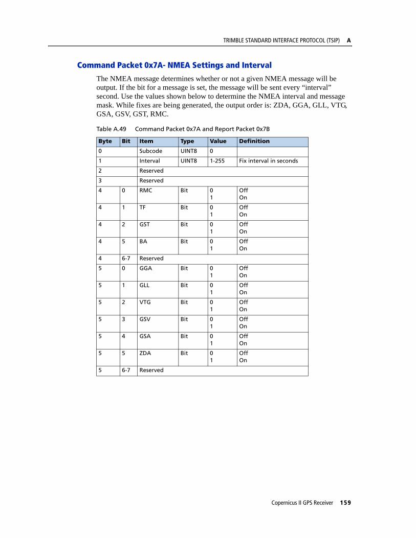
TRIMBLE STANDARD INTERFACE PROTOCOL (TSIP) A
Command Packet 0x7A- NMEA Settings and Interval
The NMEA message determines whether or not a given NMEA message will be output. If the bit for a message is set, the message will be sent every “interval” second. Use the values shown below to determine the NMEA interval and message mask. While fixes are being generated, the output order is: ZDA, GGA, GLL, VTG, GSA, GSV, GST, RMC.
Table A.49 Command Packet 0x7A and Report Packet 0x7B
Byte Bit Item Type Value Definition
0 Subcode UINT8 0
1 Interval UINT8 1-255 Fix interval in seconds
2 Reserved
3 Reserved
4 0 RMC Bit 01
OffOn
4 1 TF Bit 01
OffOn
4 2 GST Bit 01
OffOn
4 5 BA Bit 01
OffOn
4 6-7 Reserved
5 0 GGA Bit 01
OffOn
5 1 GLL Bit 01
OffOn
5 2 VTG Bit 01
OffOn
5 3 GSV Bit 01
OffOn
5 4 GSA Bit 01
OffOn
5 5 ZDA Bit 01
OffOn
5 6-7 Reserved
Copernicus II GPS Receiver 159
A TRIMBLE STANDARD INTERFACE PROTOCOL (TSIP)
Report Packet 0x7B- NMEA Settings and Interval
This packet provides the NMEA settings and interval.
Command Packet 0x7E - TAIP Message Output
TSIP packet 0x7E is used to setup the output configuration for TAIP messages. This packet expands the features similar to what have been provided by packet 0x8E-40 found in some older generation Trimble receiver products.The settings provided by the packet can be divided into 4 groups:
1. Reporting Flags – byte 1.
2. The Top-of-Hour Offset – byte 2,3. This setting applies to all eight messages included in this packet. (If different values have to be applied to each message individually, use the Time-Distance feature from TAIP protocol.)
3. Automatic Output Intervals for the 8 commonly used messages – bytes 4 - 19
4. Device ID – bytes 20-23.
This packet provides the capability to set the output frequencies for the eight commonly used messages individually. This is the same as the F<message type><output interval> command in TAIP. In contrast to packet 0x8E-40, the settings in this packet are not just for the so-called Heartbeat messages, meaning the output frequency settings are not only applied when the receiver is not generating a position fix. In practice, this packet provides a comprehensive but straightforward means to set up the TAIP output configuration. It can also be used to reset the output configuration. For example, if any of these eight messages was set up as Time-Distance mode from the TAIP protocol, this packet would reset any such message back to plain periodic output mode or no automatic output mode (frequency=0).
For customization, the settings in this packet can be stored into the Flash by either TSIP packet 0x8E-26 or TAIP command SRTSAVE_CONFIG. The flash storage commands store the latest output configuration which may be set up by either this packet or any other commands from the TAIP protocol. For example, if this packet was executed first from the TSIP protocol and then the Copernicus II GPS receiver was switched to TAIP protocol and the output settings were changed (e.g. changed to Time-Distance mode), or vise-versa, then the latest settings would be stored into the Flash (when the flash storage command is used).
Note – See Appendix D for a full explanation of the TAIP protocol. messages.
160 Copernicus II GPS Receiver

TRIMBLE STANDARD INTERFACE PROTOCOL (TSIP) A
Table A.50 Command Packet 0x7E.
Note – 0 second period means the corresponding message is not to be output at all.
Byte Bit Item Type Value Definition Default
0 Subcode UINT8 0 Setting the packet 0
1 0 ID Flag Bit 01
OffOn
0
1 CS Flag Bit 01
OffOn
1
2 EC Flag Bit 01
OffOn
1
3 FR Flag Bit 01
OffOn
1
4 CR Flag Bit 01
OffOn
0
5-7 Reserved
2,3 TOH UINT16 0-3599 Top of hour offset 0
4,5 AL output period
UINT16 0-3599 Auto output period for AL (sec)
0 (see note)
6.7 CP output period
UINT16 0-3599 Auto output period for CP (sec)
0
8,9 ID output period
UINT16 0-3599 Auto output period for ID (sec) 0
10,11 LN output period
UINT16 0-3599 Auto output period for LN (sec)
0
12,13 PV output period
UINT16 0-3599 Auto output period for PV (sec)
0
14,15 ST output period
UINT16 0-3599 Auto output period for ST (sec) 0
16,17 TM output period
UINT 16 0-3599 Auto output period for TM (sec)
0
18,19 VR output period
UINT 16 0-3599 Auto output period for VR (sec)
0
20-23 Veh ID String See TAIP ID Vehicle ID “0000”
Copernicus II GPS Receiver 161
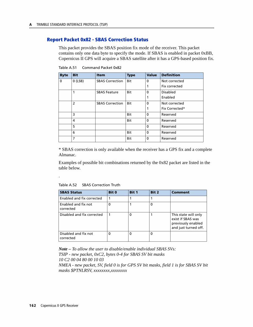
A TRIMBLE STANDARD INTERFACE PROTOCOL (TSIP)
Report Packet 0x82 - SBAS Correction Status
This packet provides the SBAS position fix mode of the receiver. This packet contains only one data byte to specify the mode. If SBAS is enabled in packet 0xBB, Copernicus II GPS will acquire a SBAS satellite after it has a GPS-based position fix.
* SBAS correction is only available when the receiver has a GPS fix and a complete Almanac.
Examples of possible bit combinations returned by the 0x82 packet are listed in the table below.
.
Note – To allow the user to disable/enable individual SBAS SVs:TSIP - new packet, 0xC2, bytes 0-4 for SBAS SV bit masks10 C2 00 04 80 00 10 03NMEA - new packet, SV, field 0 is for GPS SV bit masks, field 1 is for SBAS SV bit masks $PTNLRSV, xxxxxxxx,xxxxxxxx
Table A.51 Command Packet 0x82
Byte Bit Item Type Value Definition
0 0 (LSB) SBAS Correction Bit 0
1
Not corrected
Fix corrected
1 SBAS Feature Bit 0
1
Disabled
Enabled
2 SBAS Correction Bit 0
1
Not corrected
Fix Corrected*
3 Bit 0 Reserved
4 Bit 0 Reserved
5 0 Reserved
6 Bit 0 Reserved
7 Bit 0 Reserved
Table A.52 SBAS Correction Truth
SBAS Status Bit 0 Bit 1 Bit 2 Comment
Enabled and fix corrected 1 1 1
Enabled and fix not corrected
0 1 0
Disabled and fix corrected 1 0 1 This state will only exist if SBAS was previously enabled and just turned off.
Disabled and fix not corrected
0 0 0
162 Copernicus II GPS Receiver

TRIMBLE STANDARD INTERFACE PROTOCOL (TSIP) A
Report Packet 0x83 - Double-Precision XYZ Position Fix and Bias Information
This packet provides current GPS position fix in XYZ ECEF coordinates. If the I/O Position option is set to XYZ ECEF and the I/O Precision of Position option is set to Double (see Packet 0x35), the receiver sends this packet each time a fix is computed. The data format is shown below.
The time-of-fix is in GPS time or UTC, as selected by the I/O “timing” option.
Packet 42 provides a single-precision version of this information.
Report Packet 0x84 - Double-Precision LLA Position Fix and Bias Information
This packet provides current GPS position fix in LLA coordinates. If the I/O Position option is set to LLA and the Precision of Position option is set to Double (see Packet 0x35), the receiver sends this packet each time a fix is computed. The data format is shown below.
Note – The time-of-fix is in GPS time or UTC, as selected by the I/O “timing” option.
C WARNING – When converting from radians to degrees, significant and readily visible errors will be introduced by use of an insufficiently precise approximation for the constant p (PI). The value of the constant PI as specified in ICD-GPS-200 is 3.1415926535898.
Table A.53 Report Packet 0x83
Byte Item Type Units
0-7 X Double meters
8-15 Y Double meters
16-23 Z Double meters
24-31 clock bias Double meters
32-35 time-of-fix Single seconds
Table A.54 Report Packet 0x84
Byte Item Type Units
0-7 latitude Double radians; + for north, - for south
8-15 longitude Double radians; + for east, - for west
16-23 altitude Double meters
24-31 clock bias Double meters
32-35 time-of-fix Single seconds
Copernicus II GPS Receiver 163

A TRIMBLE STANDARD INTERFACE PROTOCOL (TSIP)
Report Packet 0x89 -Receiver Acquisition Sensitivity Mode
This packet returns the current GPS Receiver Acquisition Sensitivity Mode. The packet is output only after receipt of packet 0x69.
Packets 0x8E and 0x8F - Superpacket
See page 170 for information on Packets 0x8E and 0x8F.
Command Packet 0xBB - Navigation Configuration
In query mode, Packet 0xBB is sent with a single data byte and returns Report Packet 0xBB.
Note – This Command Packet replaces Packets 0x2C, 0x62, 0x75, and 0x77.
TSIP Packet 0xBB is used to set GPS Processing options. The table below lists the individual fields within Packet 0xBB.
Table A.55 Report Packet 0x89
Byte # Item Type Value Definition
0 Receiver Mode UINT8 0x000x01
0=Standard (default)1=High
1 Reserved UINT8 0x00
Table A.56 Command Packet 0xBB
Byte # Item Type Value Definition Default
0 Subcode UINT8 0x00 Query mode
Table A.57 Command and Report Packet 0xBB
Byte # Item Type Value Definition Default
0 Subcode UINT8 0x00 Query mode 0x00
1 Reserved
2 SBAS UINT8 01
WAAS_OFF WAAS_AUTO
WAAS_AUTO
3 Dynamics Code UINT8 1234
LandSeaAirStationary/Over Determined
Land
4 Reserved
5-8 Elevation Mask Single 0.0 - 1.57(radian)
Lowest satellite elevation for fixes
0.0873 (5o)
9-12 Reserved
13-16 Reserved
17-20 Reserved
164 Copernicus II GPS Receiver

TRIMBLE STANDARD INTERFACE PROTOCOL (TSIP) A
Note – The dynamic limits for Dynamics Codes are:Land: acceleration < 10m/s2; velocity < 120m/s; altitude >-2000m, <9000mSea: acceleration < 10m/s2; velocity < 45m/s; altitude >-2000m, <9000mAir: acceleration < 40m/s2; velocity < 515m/s; altitude >-2000m, <50000m
Note – Byte #2 is for all SBAS, not just WAAS.
Command Packet 0xBC - Protocol Configuration
TSIP Packet 0xBC is used to query the port characteristics. In query mode, Packet 0xBC is sent with a single data byte and returns Report Packet 0xBC. (See Table A.4 for information on saving the settings to non-volatile memory.)
TSIP Packet 0xBC is used to set the communication parameters on port A. The table below lists the individual fields within the Packet 0xBC and provides query field descriptions. The BC command settings are retained in battery-backed RAM.
21 Reserved
22-39 Reserved
Table A.58 Command Packet 0xBC
Byte Bit Item Type Value Definition
0 Port to Set UINT 8 010xFF
Port APort BCurrent port
1 Input Baud Rate UINT 8 234567891011
ReservedReservedReservedReserved4800 baud9600 baud19200 baud38400 baud57600 baud115200 baud
2 Output Baud Rate UINT 8 As above As above (Note 1)
3 # Data Bits UINT 8 3 8 bits
4 Parity UINT 8 0 None
5 # Stop Bits UINT 8 0 1 bit
6 Flow Control UINT 8 0 0 = none
7 0 TAIP Bit 01
OffOn
1 TSIP input Bit 01
OffOn
Table A.57 Command and Report Packet 0xBB (continued)
Byte # Item Type Value Definition Default
Copernicus II GPS Receiver 165

A TRIMBLE STANDARD INTERFACE PROTOCOL (TSIP)
Note – The Copernicus II GPS receiver requires that the input and output baud rates be identical.
2 NMEA input Bit 0
1
Off
On
3 Reserved
4-7 Reserved
8 0 TAIP Bit 01
OffOn
1 TSIP output Bit 01
OffOn
2 NMEA output Bit 01
OffOn
3-7 Reserved
9 Reserved
Table A.58 Command Packet 0xBC
Byte Bit Item Type Value Definition
166 Copernicus II GPS Receiver

TRIMBLE STANDARD INTERFACE PROTOCOL (TSIP) A
Command Packet 0xC0 - Graceful Shutdown and Go To Standby Mode
TSIP Packet 0xC0 is used to issue a reset or graceful shutdown to the unit and/or command the unit into Standby Mode.
The table below lists the individual fields within the Packet 0xC0 and provides query field descriptions. Any combination of conditions in byte 2 can be specified for starting up the unit from standby mode. The condition that happens first will trigger the unit to start up. If byte 2, bit 2 is set to 1, then byte 3 must be greater than 0.
Table A.59 Command Packet 0xC0
The settings will be saved to flash when the user issues the command to “Save User Configuration to Flash”.
Byte Bit Item Type Value Definition
0 Reset type or go to standby mode
BYTE 'H'‘W’‘C’
‘S’‘F’
hot startwarm startcold start
standby modefactory reset
1 Store BBRAM to Flash flag
BYTE 0 Reserved
1 Reserved
2 Store user configuration to Flash Memory
3 Store user configuration to Flash memory
4 Erase Almanac, ephemeris and last position from Flash Memory
5 Erase user configuration from Flash Memory and BBRAM
6 Erase Almanac, ephemeris, last position and user configuration from Flash Memory and BBRAM
2 0 Start-up from Standby Mode condition flags
BYTE 01
1=start up on serial port A activity
1 01
1=start up on serial port B activity
2 01
1=start up after RTC alarm elapsed
3-4 Number of seconds to stay in Standby mode
UINT32 0 to 2147483647or0 to (231 - 1)
seconds
Copernicus II GPS Receiver 167

A TRIMBLE STANDARD INTERFACE PROTOCOL (TSIP)
Command Packet 0xC2 - SBAS SV Mask.
This packet provides the SBAS SV bit mask in four bytes. The user data packet contains four bytes to specify 19 possible SBAS prn numbers. Bit 0 represents PRN 120.
Available WAAS PRN numbers are 135 and 138.
Message format is:
<DLE> <id> <byte 3> <byte 2> <byte 1> <byte 0> <DLE> <ETX>
To disable WAAS PRN 135 send 10 C2 00 00 80 00 10 03
To disable WAAS PRN 138 send 10 C2 00 04 00 00 10 03
To enable all WAAS send 10 C2 00 00 00 00 10 03
168 Copernicus II GPS Receiver

TRIMBLE STANDARD INTERFACE PROTOCOL (TSIP) A
TSIP SuperpacketsSeveral packets have been added to the core TSIP protocol to provide additional capability for OEM receivers. In OEM Packets 0x8E and their 0x8F responses, the first data byte is a sub-code which indicates the superpacket type. For example, in Packet 0x8E-15, 15 is the sub-code that indicates the superpacket type. Therefore the ID code for OEM packets is 2 bytes long followed by the data. Command packet 0x35 is used to enable superpackets.
Command Packet 8E-15 - Set/Request Datum
This packet allows the user to change the default datum from WGS-84 to one of 180 selected datums. The datum is a set of 5 parameters which describe an ellipsoid to convert the GPS receiver’s internal coordinate system of XYZ ECEF into Latitude, Longitude, and Altitude (LLA). This affects all calculations of LLA in packets 0x4A and 0x84.
The datum can be changed to match coordinates with another system such as a map. Most maps are marked with the datum used. In the US, the most popular datum for maps is NAD-27. You may choose a datum optimized for the local shape of the earth, however optimized datums are truly local and provide very different results when used outside of the area for which they are intended. WGS-84 is an excellent general ellipsoid valid around the world. To request the current datum setting, one data byte is sent. Report Packet 0x8F is returned.
Table A.60 Command Packet 8E-15
To change to one of the internally held datums, the packet must contain exactly 2 bytes representing the integer value of the index of the desired datum.
Table A.61 Command Packet 8E-15
Note – To request the current datum, send Packet 8E015 with no data bytes.
Byte Type Meaning
0 Superpacket 0x15
Byte Type Meaning
0 Superpacket ID 0x15
1-2 INT16 Datum index
Copernicus II GPS Receiver 169
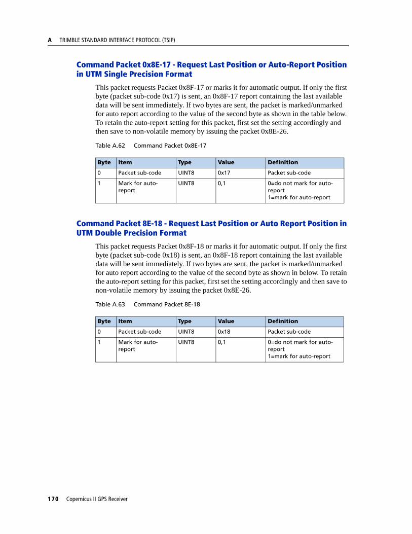
A TRIMBLE STANDARD INTERFACE PROTOCOL (TSIP)
Command Packet 0x8E-17 - Request Last Position or Auto-Report Position in UTM Single Precision Format
This packet requests Packet 0x8F-17 or marks it for automatic output. If only the first byte (packet sub-code 0x17) is sent, an 0x8F-17 report containing the last available data will be sent immediately. If two bytes are sent, the packet is marked/unmarked for auto report according to the value of the second byte as shown in the table below. To retain the auto-report setting for this packet, first set the setting accordingly and then save to non-volatile memory by issuing the packet 0x8E-26.
Table A.62 Command Packet 0x8E-17
Command Packet 8E-18 - Request Last Position or Auto Report Position in UTM Double Precision Format
This packet requests Packet 0x8F-18 or marks it for automatic output. If only the first byte (packet sub-code 0x18) is sent, an 0x8F-18 report containing the last available data will be sent immediately. If two bytes are sent, the packet is marked/unmarked for auto report according to the value of the second byte as shown in below. To retain the auto-report setting for this packet, first set the setting accordingly and then save to non-volatile memory by issuing the packet 0x8E-26.
Table A.63 Command Packet 8E-18
Byte Item Type Value Definition
0 Packet sub-code UINT8 0x17 Packet sub-code
1 Mark for auto-report
UINT8 0,1 0=do not mark for auto-report1=mark for auto-report
Byte Item Type Value Definition
0 Packet sub-code UINT8 0x18 Packet sub-code
1 Mark for auto-report
UINT8 0,1 0=do not mark for auto-report1=mark for auto-report
170 Copernicus II GPS Receiver
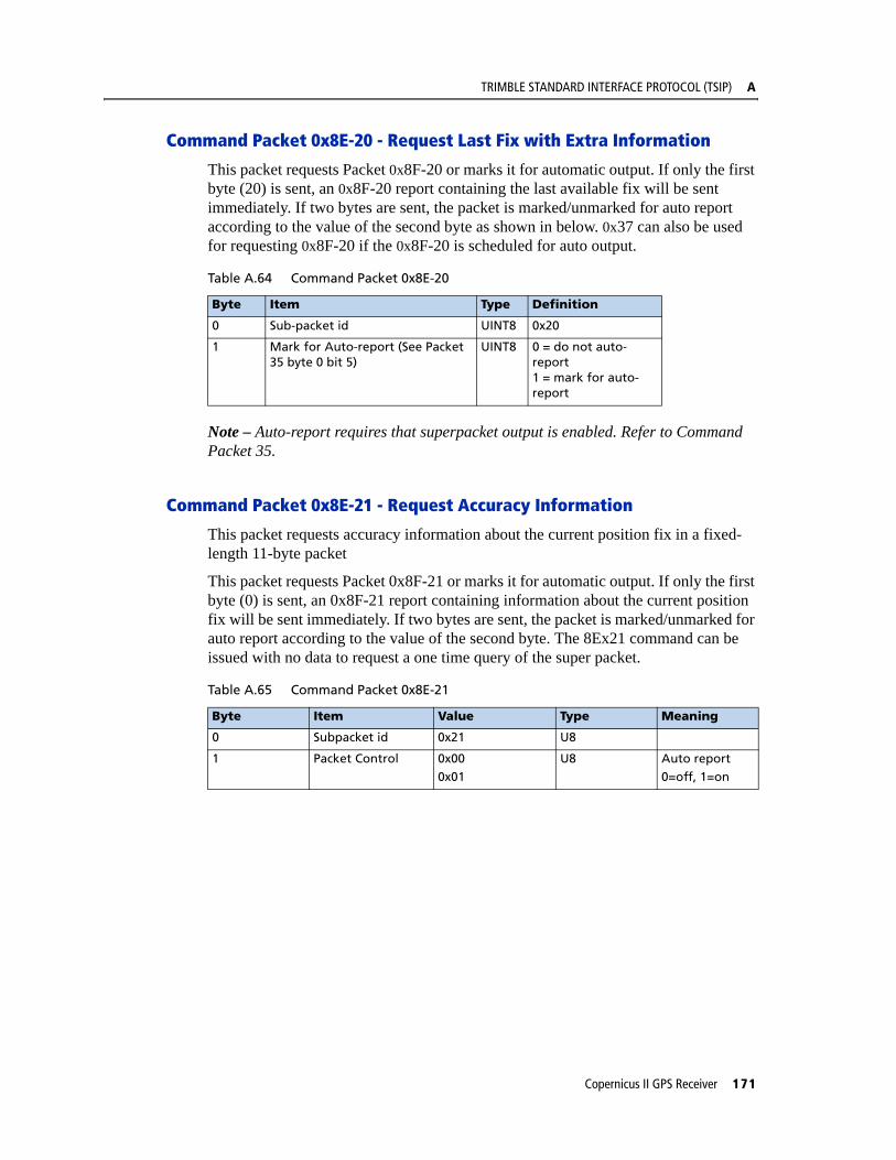
TRIMBLE STANDARD INTERFACE PROTOCOL (TSIP) A
Command Packet 0x8E-20 - Request Last Fix with Extra Information
This packet requests Packet 0x8F-20 or marks it for automatic output. If only the first byte (20) is sent, an 0x8F-20 report containing the last available fix will be sent immediately. If two bytes are sent, the packet is marked/unmarked for auto report according to the value of the second byte as shown in below. 0x37 can also be used for requesting 0x8F-20 if the 0x8F-20 is scheduled for auto output.
Note – Auto-report requires that superpacket output is enabled. Refer to Command Packet 35.
Command Packet 0x8E-21 - Request Accuracy Information
This packet requests accuracy information about the current position fix in a fixed-length 11-byte packet
This packet requests Packet 0x8F-21 or marks it for automatic output. If only the first byte (0) is sent, an 0x8F-21 report containing information about the current position fix will be sent immediately. If two bytes are sent, the packet is marked/unmarked for auto report according to the value of the second byte. The 8Ex21 command can be issued with no data to request a one time query of the super packet.
Table A.64 Command Packet 0x8E-20
Byte Item Type Definition
0 Sub-packet id UINT8 0x20
1 Mark for Auto-report (See Packet 35 byte 0 bit 5)
UINT8 0 = do not auto-report1 = mark for auto-report
Table A.65 Command Packet 0x8E-21
Byte Item Value Type Meaning
0 Subpacket id 0x21 U8
1 Packet Control 0x000x01
U8 Auto report0=off, 1=on
Copernicus II GPS Receiver 171

A TRIMBLE STANDARD INTERFACE PROTOCOL (TSIP)
Command Packet 0x8E-23 - Request Last Compact Fix Information
This packet requests complete information about the current position velocity fix in a compact, fixed-length 29-byte packet. The Copernicus II GPS will respond with Report Packet 0x8F-23. The packet comes out when queried, or when there is a new fix while operating in auto-output mode.
This packet requests Packet 0x8F-23 or marks it for automatic output. If only the first byte (0) is sent, an 0x8F-23 report containing information about the last position fix will be sent immediately. If two bytes are sent, the packet is marked/unmarked for auto report according to the value of the second byte. The 8Ex23 command can be issued with no data to request a one time query of the super packet.
Command Packet 0x8E-26 - Non-Volatile Memory Storage
The 0x8E-26 command is issued with no data to cause the current settings to be saved to non-volatile memory. The 0x8F-26 report is generated after the values have been saved.
Command Packet 0x8E-2A - Request Fix and Channel Tracking Info, Type 1
This packet requests Packet 0x8F-2A or marks it for automatic output. If only the first byte (packet sub-code 0x2A) is sent, an 0x8F-2A report containing the last available data will be sent immediately. If two bytes are sent, the packet is marked/unmarked for auto report according to the value of the second byte as shown in below.
To retain the auto-report setting for this packet, first set the setting accordingly and then save to non-volatile memory by issuing the packet 0x8E-26.
Table A.68 Command Packet 0x8E-2A
Table A.66 Command Packet 0x8E-23
Byte Item Value Type Meaning
0 Subpacket id 0x23 U8
1 Packet Control 0x000x01
U8 Auto report0=off, 1=on
Table A.67 Command Packet 0x8E-26
Byte Item Type Value Definition
0 Subcode UINT8 0x26 Save Settings
Byte Item Type Value Definition
0 Packet sub-code UINT8 0x2A Packet sub-code
1 Mark for Auto-report
UINT8 0,1 0 = do not auto-report1 = mark for auto-report
172 Copernicus II GPS Receiver
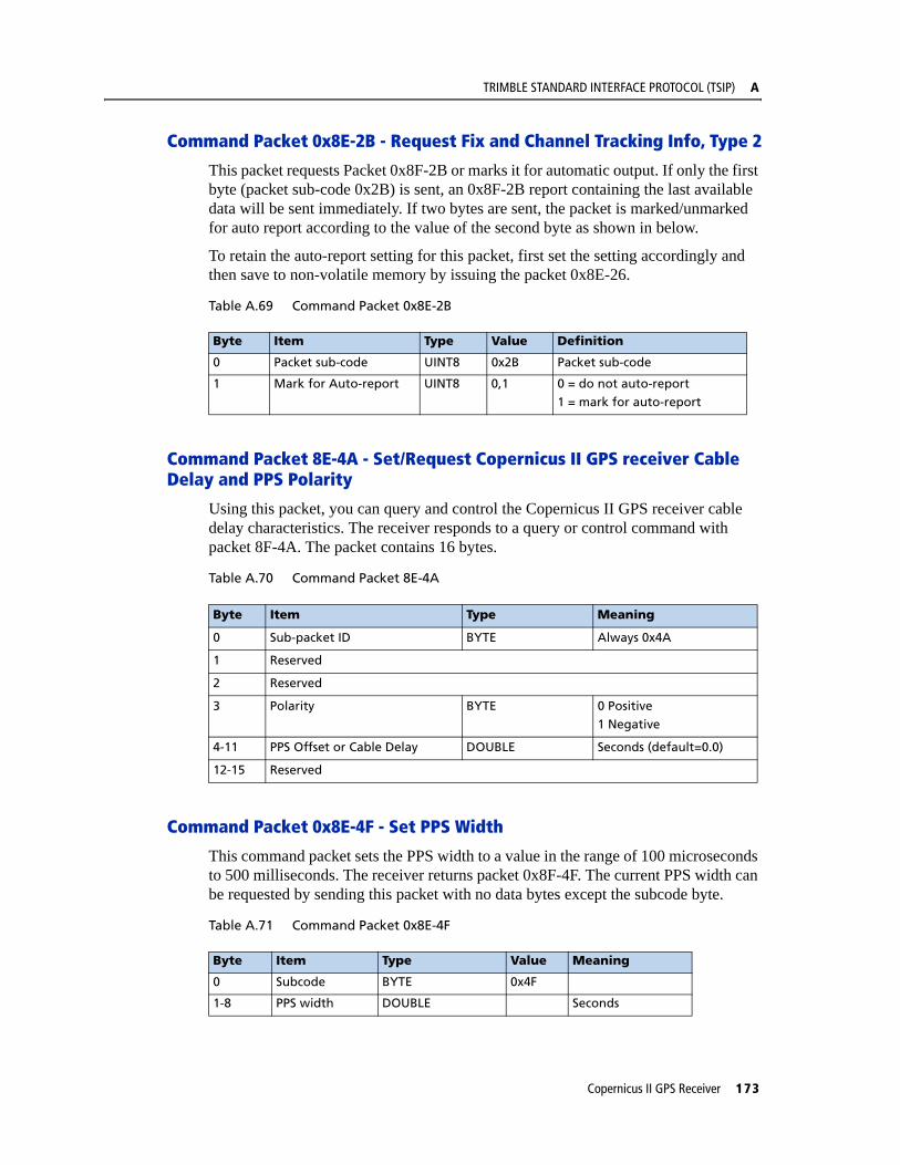
TRIMBLE STANDARD INTERFACE PROTOCOL (TSIP) A
Command Packet 0x8E-2B - Request Fix and Channel Tracking Info, Type 2
This packet requests Packet 0x8F-2B or marks it for automatic output. If only the first byte (packet sub-code 0x2B) is sent, an 0x8F-2B report containing the last available data will be sent immediately. If two bytes are sent, the packet is marked/unmarked for auto report according to the value of the second byte as shown in below.
To retain the auto-report setting for this packet, first set the setting accordingly and then save to non-volatile memory by issuing the packet 0x8E-26.
Table A.69 Command Packet 0x8E-2B
Command Packet 8E-4A - Set/Request Copernicus II GPS receiver Cable Delay and PPS Polarity
Using this packet, you can query and control the Copernicus II GPS receiver cable delay characteristics. The receiver responds to a query or control command with packet 8F-4A. The packet contains 16 bytes.
Table A.70 Command Packet 8E-4A
Command Packet 0x8E-4F - Set PPS Width
This command packet sets the PPS width to a value in the range of 100 microseconds to 500 milliseconds. The receiver returns packet 0x8F-4F. The current PPS width can be requested by sending this packet with no data bytes except the subcode byte.
Table A.71 Command Packet 0x8E-4F
Byte Item Type Value Definition
0 Packet sub-code UINT8 0x2B Packet sub-code
1 Mark for Auto-report UINT8 0,1 0 = do not auto-report
1 = mark for auto-report
Byte Item Type Meaning
0 Sub-packet ID BYTE Always 0x4A
1 Reserved
2 Reserved
3 Polarity BYTE 0 Positive1 Negative
4-11 PPS Offset or Cable Delay DOUBLE Seconds (default=0.0)
12-15 Reserved
Byte Item Type Value Meaning
0 Subcode BYTE 0x4F
1-8 PPS width DOUBLE Seconds
Copernicus II GPS Receiver 173

A TRIMBLE STANDARD INTERFACE PROTOCOL (TSIP)
Report Packet 0x8F-15 - Current Datum Values
This packet contains 43 data bytes with the values for the datum currently in use, and is sent in response to Packet 0x8E-15. Both the datum index and the 5 double precision values for that index will be returned.
Table A.72 Report Packet 0x8F-15
Note – A complete list of datums is provided at the end of this appendix. Eccentricity Squared is related to flattening by the following equation: e2=2p-p2.
Byte Type Meaning
0 UINT8 ID for this sub-packet (always x15)
1-2 INT16 Datum index
3-10 Double DX
11-18 Double DY
19-26 Double DZ
27-34 Double A=axis
35-42 Double Eccentricity Squared
174 Copernicus II GPS Receiver
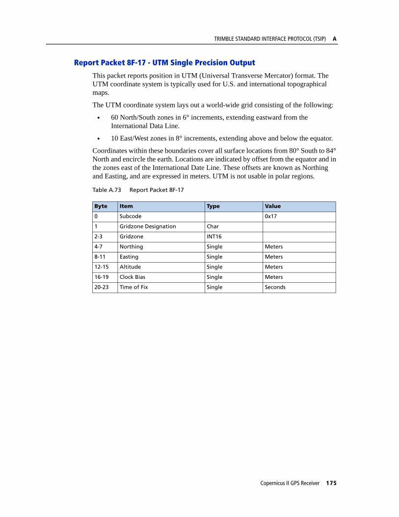
TRIMBLE STANDARD INTERFACE PROTOCOL (TSIP) A
Report Packet 8F-17 - UTM Single Precision Output
This packet reports position in UTM (Universal Transverse Mercator) format. The UTM coordinate system is typically used for U.S. and international topographical maps.
The UTM coordinate system lays out a world-wide grid consisting of the following:
• 60 North/South zones in 6° increments, extending eastward from the International Data Line.
• 10 East/West zones in 8° increments, extending above and below the equator.
Coordinates within these boundaries cover all surface locations from 80° South to 84° North and encircle the earth. Locations are indicated by offset from the equator and in the zones east of the International Date Line. These offsets are known as Northing and Easting, and are expressed in meters. UTM is not usable in polar regions.
Table A.73 Report Packet 8F-17
Byte Item Type Value
0 Subcode 0x17
1 Gridzone Designation Char
2-3 Gridzone INT16
4-7 Northing Single Meters
8-11 Easting Single Meters
12-15 Altitude Single Meters
16-19 Clock Bias Single Meters
20-23 Time of Fix Single Seconds
Copernicus II GPS Receiver 175
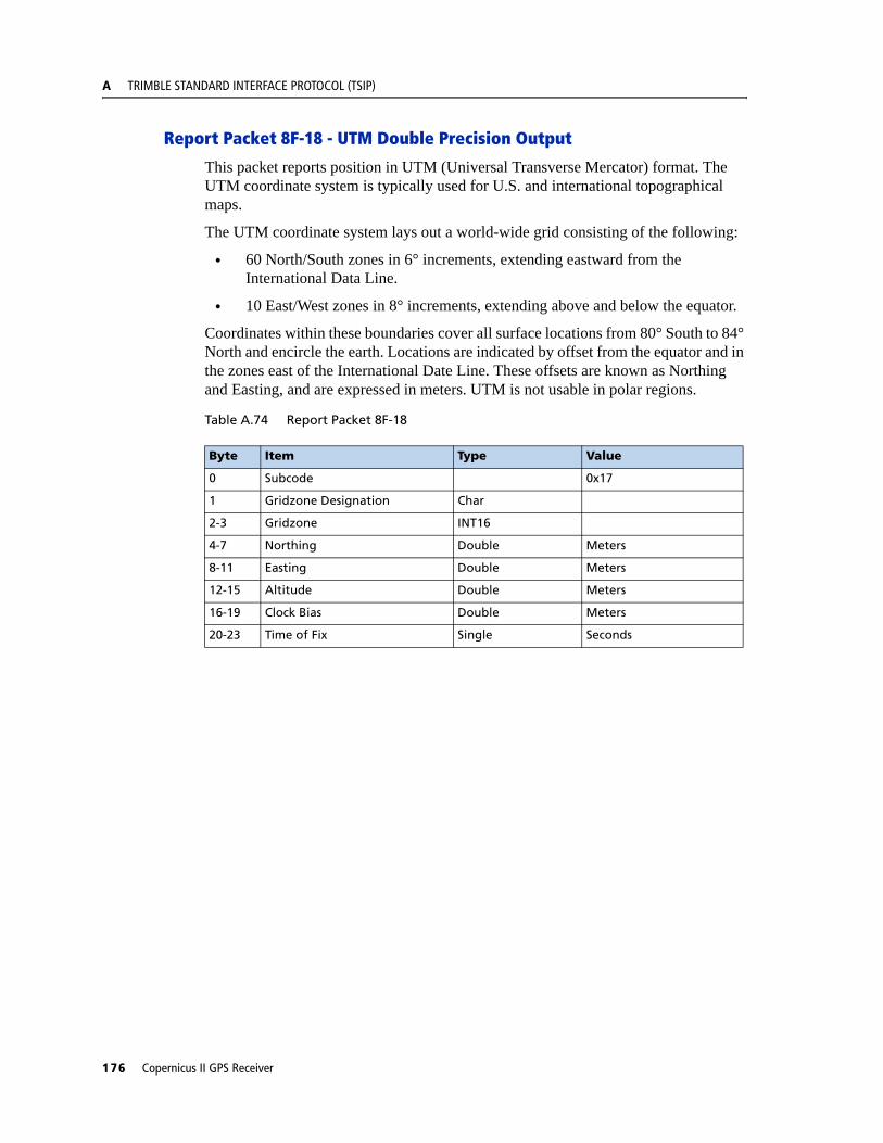
A TRIMBLE STANDARD INTERFACE PROTOCOL (TSIP)
Report Packet 8F-18 - UTM Double Precision Output
This packet reports position in UTM (Universal Transverse Mercator) format. The UTM coordinate system is typically used for U.S. and international topographical maps.
The UTM coordinate system lays out a world-wide grid consisting of the following:
• 60 North/South zones in 6° increments, extending eastward from the International Data Line.
• 10 East/West zones in 8° increments, extending above and below the equator.
Coordinates within these boundaries cover all surface locations from 80° South to 84° North and encircle the earth. Locations are indicated by offset from the equator and in the zones east of the International Date Line. These offsets are known as Northing and Easting, and are expressed in meters. UTM is not usable in polar regions.
Table A.74 Report Packet 8F-18
Byte Item Type Value
0 Subcode 0x17
1 Gridzone Designation Char
2-3 Gridzone INT16
4-7 Northing Double Meters
8-11 Easting Double Meters
12-15 Altitude Double Meters
16-19 Clock Bias Double Meters
20-23 Time of Fix Single Seconds
176 Copernicus II GPS Receiver

TRIMBLE STANDARD INTERFACE PROTOCOL (TSIP) A
Report Packet 0x8F-20 - Last Fix with Extra Information (binary fixed point)
This packet provides complete information about the current position velocity fix in a compact, fixed-length 56-byte packet. The fields are fixed-point with precision matched to the receiver accuracy. It can be used for automatic position/velocity reports. The latest fix can also be requested by 0x8E-20 or 0x37 commands.The data format is shown below.
Table A.75 Report Packet 0x8F-20
Byte Bit Item Type Value Definition
0 Sub-packet id UINT8 Id for this sub-packet (always 0x20)
1 Reserved UINT8 Reserved
2-3 East velocity INT16 0.005 m/s or 0.020 m/sSee Note 1.
4-5 North velocity INT16 0.005 m/s or 0.020 m/sSee Note 1.
6-7 Up velocity INT16 0.005 m/s or 0.020 m/s See Note 1.
8-11 Time Of Week UINT32 GPS Time in milliseconds
12-15 Latitude INT32 -230 to 230 WGS-84 latitude, 2-31
semicircle (-90 - 90 )
16-19 Longitude UINT32 0 to 232 WGS-84 longitude, 2-31
semicircle (0 - 360 )
20-23 Altitude INT32 Altitude above WGS-84 ellipsoid, mm.
24 0 Velocity Scaling 01
0.005 m/s2
0.020 m/s2
1-7 reserved
25 reserved
26 Datum Datum index + 1, 0=unknown
27 0 Invalid Fix Bit 01
No (Valid Fix)Yes (Invalid Fix)
1 Reserved Bit 0 Reserved
2 Fix Dimension Bit 01
3D2D
3 Alt Hold Bit 01
Last 3D AltitudeUser-entered altitude
4 Filtered Bit 01
UnfilteredFiltered
5-7 reserved
28 NumSVs UINT8 Number of satellites used for fix. Will be zero if no fix avail.
29 UTC Offset UINT8 Number of leap seconds between UTC and GPS time.
30-31 Week INT16 GPS time of fix, weeks.
Copernicus II GPS Receiver 177

A TRIMBLE STANDARD INTERFACE PROTOCOL (TSIP)
Note – Velocity scale controlled by byte 24, bit 1. Overflow = 0x8000.
32 0-5 PRN 1 UINT8 1-32 PRN of first satellite
6-7 reserved
33 IODE 1 UINT8 IODE of first satellite
34 0-5 PRN 2 UINT8 1-32 PRN of second satellite
6-7 reserved
35 IODE 2 UINT8 IODE of second satellite
36 0-5 PRN 3 UINT8 1-32 PRN of third satellite
6-7 reserved
37 IODE 3 UINT8 IODE of third satellite
38 0-5 PRN 4 UINT8 1-32 PRN of fourth satellite
6-7 reserved
39 IODE 4 UINT8 IODE of fourth satellite
40 0-5 PRN 5 UINT8 1-32 PRN of fifth satellite
6-7 reserved
41 IODE 5 UINT8 IODE of fifth satellite
42 0-5 PRN 6 UINT8 1-32 PRN of sixth satellite
6-7 reserved
43 IODE 6 UINT8 IODE of sixth satellite
44 0-5 PRN 7 UINT8 1-32 PRN of seventh satellite
6-7 reserved
45 IODE 7 UINT8 IODE of seventh satellite
46 0-5 PRN 8 UINT8 1-32 PRN of eighth satellite
6-7 reserved
47 IODE 8 UINT8 IODE of eighth satellite
48 0-5 PRN 9 UINT8 1-32 PRN of ninth satellite
6-7 reserved
49 IODE 9 UNIT8 IODE of ninth satellite
50 0-5 PRN 10 UINT8 1-32 PRN of tenth satellite
6-7 reserved
51 IODE 10 UNIT8 IODE of tenth satellite
52 0-5 PRN 11 UINT8 1-32 PRN of eleventh satellite
6-7 reserved
53 IODE 11 UNIT8 IODE of eleventh satellite
54 0-5 PRN 12 UINT8 1-32 PRN of twelfth satellite
6-7 reserved
55 IODE 12 UINT8 IODE of twelfth satellite
56-63 Ionospheric parameters
Table A.75 Report Packet 0x8F-20
Byte Bit Item Type Value Definition
178 Copernicus II GPS Receiver

TRIMBLE STANDARD INTERFACE PROTOCOL (TSIP) A
Report Packet 0x8F-21 - Request Accuracy Information
This packet returns accuracy information about the current position fix, in a fixed-length 11-byte packet. The packet comes out every second.
Report Packet 0x8F-23 - Request Last Compact Fix Information
This packet returns complete information about the current position velocity fix in a compact, fixed-length 29-byte packet. The packet becomes active when queried with packet 0x8E-23, or when a new fix is generated in Auto-Output mode.
Table A.76 Report Packet 0x8F-21
Byte Item Value Type Range Meaning
0 Subpacket id 0x21 U8 Packet sub-code (always 0x21).
1 Format type 0x01 U8
2 - 3 East uncertainty Fixed point, quantum = 0.01m
U16 Range = [0, 320] m 0xFFFF = no uncertainty0xFFFE = overflow
4 - 5 North Uncertainty
Fixed point, quantum = 0.01m
U16 Range = [0, 320] m 0xFFFF = no uncertainty0xFFFE = overflow
6 - 7 Vertical Uncertainty
Fixed point, quantum = 0.01m
U16 Range = [0, 320] m 0xFFFF = no uncertainty0xFFFE = overflow
8 - 9 Time Uncertainty Fixed point, quantum = 0.01m
U16 Range = [0, 320] m 0xFFFF = no uncertainty0xFFFE = overflow
10-11 East/North Correlation
Fixed point, quantum = 0.0001 (unit less)
S16 Range = [-1, 1]
12 Fix Age Quantum = 1 s U8 Range = [0, 253] 0xFFFF = no fix yet0xFFFE = overflow
Table A.77 Report Packet 0x8F-23
Byte Bit Item Value Type Meaning
0 Subpacket id 0x23 U8
1 -4 Fix Time GPS Time of Week, ms
U32
5 - 6 Week Number 10-bit (?) week number
U16
7 Leap Second UTC/GPS offset U8
8 Fix Available 1 = no fix available
1 DGPS 1 DGPS
2 2D 1 2-D fix
3 - 4 Reserved Reserved
5 Velocity Scale 0
1
0.005 m/s2
0.020 m/s2
6 - 7 Reserved Reserved
Copernicus II GPS Receiver 179

A TRIMBLE STANDARD INTERFACE PROTOCOL (TSIP)
The above packet in auto-output mode maybe used in lieu of the 0x6D and 0x42, 0x4A, 0x83, 0x84, or 0x8F-20 position/velocity reports
Report Packet 0x8F-26 - Non-Volatile Memory Status
This report will be issued after an 0x8E-26 command.
Table A.78 Report Packet 0x8F-26
9 - 12 Latitudes -2^30 to 2^30 S32 WGS-84 latitude, 2^-31
semicircle (-90 - 90)
13 - 16 Longitude 0 to 2^32 U32 WGS-84 longitude, 2^-31
semicircle (0 - 360)
17 - 20 Altitude S32 Altitude above WGS-84
ellipsoid, mm.
21 - 22 Velocity East 0.005 m/s or 0.020 m/s
S16 quantum depends on Velocity Scale
23 - 24 Velocity North 0.005 m/s or 0.020 m/s
S16 quantum depends on Velocity Scale
25 - 26 Velocity Up 0.005 m/s or 0.020 m/s
S16 quantum depends on Velocity Scale
27 - 28 Reserved U16
Byte Item Type Value Definition
0 Subcode UINT8 0x26 Save settings
1-4 Reserved
Table A.77 Report Packet 0x8F-23
Byte Bit Item Value Type Meaning
180 Copernicus II GPS Receiver
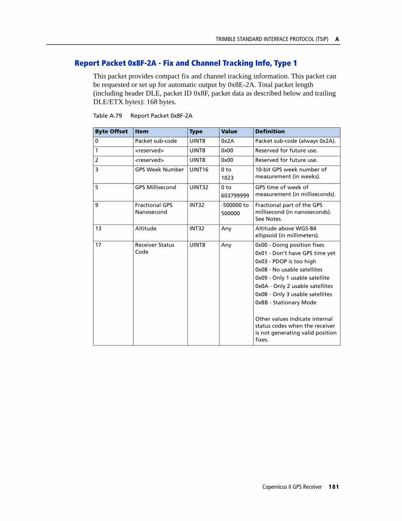
TRIMBLE STANDARD INTERFACE PROTOCOL (TSIP) A
Report Packet 0x8F-2A - Fix and Channel Tracking Info, Type 1
This packet provides compact fix and channel tracking information. This packet can be requested or set up for automatic output by 0x8E-2A. Total packet length (including header DLE, packet ID 0x8F, packet data as described below and trailing DLE/ETX bytes): 168 bytes.
Table A.79 Report Packet 0x8F-2A
Byte Offset Item Type Value Definition
0 Packet sub-code UINT8 0x2A Packet sub-code (always 0x2A).
1 <reserved> UINT8 0x00 Reserved for future use.
2 <reserved> UINT8 0x00 Reserved for future use.
3 GPS Week Number UINT16 0 to
1023
10-bit GPS week number of measurement (in weeks).
5 GPS Millisecond UINT32 0 to
603799999
GPS time of week of measurement (in milliseconds).
9 Fractional GPS Nanosecond
INT32 -500000 to
500000
Fractional part of the GPS millisecond (in nanoseconds). See Notes.
13 Altitude INT32 Any Altitude above WGS-84 ellipsoid (in millimeters).
17 Receiver Status Code
UINT8 Any 0x00 - Doing position fixes0x01 - Don't have GPS time yet
0x03 - PDOP is too high0x08 - No usable satellites0x09 - Only 1 usable satellite
0x0A - Only 2 usable satellites0x0B - Only 3 usable satellites0xBB - Stationary Mode
Other values indicate internal status codes when the receiver is not generating valid position fixes.
Copernicus II GPS Receiver 181
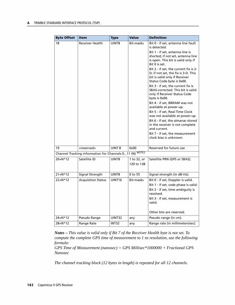
A TRIMBLE STANDARD INTERFACE PROTOCOL (TSIP)
Notes – This value is valid only if Bit 7 of the Receiver Health byte is not set. To compute the complete GPS time of measurement to 1 ns resolution, use the following formula:GPS Time of Measurement (nanosec) = GPS Millisec*1000000 + Fractional GPS Nanosec
The channel tracking block (12 bytes in length) is repeated for all 12 channels.
18 Receiver Health UINT8 Bit-masks Bit 0 - if set, antenna line fault is detected.
Bit 1 - if set, antenna line is shorted; if not set, antenna line is open. This bit is valid only if Bit 0 is set.Bit 2 - if set, the current fix is 2-D; if not set, the fix is 3-D. This bit is valid only if Receiver Status Code byte is 0x00.Bit 3 - if set, the current fix is SBAS-corrected. This bit is valid only if Receiver Status Code byte is 0x00.
Bit 4 - if set, BBRAM was not available at power-up.Bit 5 - if set, Real-Time Clock was not available at power-up.Bit 6 - if set, the almanac stored in the receiver is not complete and current.
Bit 7 - if set, the measurement clock bias is unknown.
19 <reserved> UINT 8 0x00 Reserved for future use
Channel Tracking information for Channels 0...11 (N) NOTE2
20+N*12 Satellite ID UINT8 1 to 32, or
120 to 138
Satellite PRN (GPS or SBAS).
21+N*12 Signal Strength UINT8 0 to 55 Signal strength (in dB-Hz).
22+N*12 Acquisition Status UINT16 Bit-masks Bit 0 - if set, Doppler is valid.
Bit 1 - if set, code phase is valid.Bit 2 - if set, time ambiguity is resolved.Bit 3 - if set, measurement is valid.
Other bits are reserved.
24+N*12 Pseudo Range UINT32 any Pseudo range (in cm).
28+N*12 Range Rate INT32 any Range rate (in millimeters/sec).
Byte Offset Item Type Value Definition
182 Copernicus II GPS Receiver
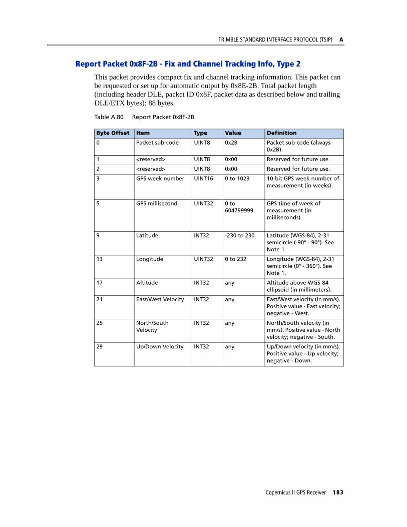
TRIMBLE STANDARD INTERFACE PROTOCOL (TSIP) A
Report Packet 0x8F-2B - Fix and Channel Tracking Info, Type 2
This packet provides compact fix and channel tracking information. This packet can be requested or set up for automatic output by 0x8E-2B. Total packet length (including header DLE, packet ID 0x8F, packet data as described below and trailing DLE/ETX bytes): 88 bytes.
Table A.80 Report Packet 0x8F-2B
Byte Offset Item Type Value Definition
0 Packet sub-code UINT8 0x2B Packet sub-code (always 0x2B).
1 <reserved> UINT8 0x00 Reserved for future use.
2 <reserved> UINT8 0x00 Reserved for future use.
3 GPS week number UINT16 0 to 1023 10-bit GPS week number of measurement (in weeks).
5 GPS millisecond UINT32 0 to 604799999
GPS time of week of measurement (in milliseconds).
9 Latitude INT32 -230 to 230 Latitude (WGS-84), 2-31 semicircle (-90° - 90°). See Note 1.
13 Longitude UINT32 0 to 232 Longitude (WGS-84), 2-31 semicircle (0° - 360°). See Note 1.
17 Altitude INT32 any Altitude above WGS-84 ellipsoid (in millimeters).
21 East/West Velocity INT32 any East/West velocity (in mm/s). Positive value - East velocity; negative - West.
25 North/South Velocity
INT32 any North/South velocity (in mm/s). Positive value - North velocity; negative - South.
29 Up/Down Velocity INT32 any Up/Down velocity (in mm/s). Positive value - Up velocity; negative - Down.
Copernicus II GPS Receiver 183
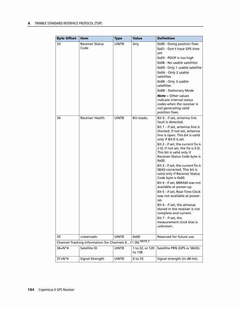
A TRIMBLE STANDARD INTERFACE PROTOCOL (TSIP)
33 Receiver Status Code
UINT8 Any 0x00 - Doing position fixes
0x01 - Don't have GPS time yet0x03 - PDOP is too high0x08 - No usable satellites
0x09 - Only 1 usable satellite0x0A - Only 2 usable satellites0x0B - Only 3 usable satellites
0xBB - Stationary Mode
Note – Other values indicate internal status codes when the receiver is not generating valid position fixes.
34 Receiver Health UINT8 Bit-masks Bit 0 - if set, antenna line fault is detected.
Bit 1 - if set, antenna line is shorted; if not set, antenna line is open. This bit is valid only if Bit 0 is set.Bit 2 - if set, the current fix is 2-D; if not set, the fix is 3-D. This bit is valid only if Receiver Status Code byte is 0x00.
Bit 3 - if set, the current fix is SBAS-corrected. This bit is valid only if Receiver Status Code byte is 0x00.Bit 4 - if set, BBRAM was not available at power-up.Bit 5 - if set, Real-Time Clock was not available at power-up.
Bit 6 - if set, the almanac stored in the receiver is not complete and current.Bit 7 - if set, the measurement clock bias is unknown.
35 <reserved> UINT8 0x00 Reserved for future use.
Channel Tracking information for Channels 0…11 (N) NOTE 2
36+N*4 Satellite ID UINT8 1 to 32, or 120 to 138
Satellite PRN (GPS or SBAS).
37+N*4 Signal Strength UINT8 0 to 55 Signal strength (in dB-Hz).
Byte Offset Item Type Value Definition
184 Copernicus II GPS Receiver

TRIMBLE STANDARD INTERFACE PROTOCOL (TSIP) A
Note – To convert to radians, multiply the received latitude or longitude value by (PI/231). For longitude, if the converted value is greater than PI, subtract 2*PI (PI = 3.1415926535898) to bring the final value to the (-PI…+PI) range.
The channel tracking block (4 bytes in length) is repeated for all 12 channels.
Response Packet 8f-4A - Copernicus II GPS Receiver Cable Delay and POS Polarity
This report packet is output after the 0x8E-4A command packet has been executed. The packet contains 16 bytes.
Table A.81 Response Packet 8F-4A
Report Packet 0x8F-4F - Set PPS Width
Note – This report packet is output after the command packet 0x8E-4E has been executed. See the corresponding command packet for information about the data formats.
38+N*4 Measurement Status
UINT8 Bit-masks Bit 2 - if set, time ambiguity is resolved (channel is acquired).
Bit 4 - if set, ephemeris is decoded.Other bits are reserved.
39+N*4 Fix Mode / Rejection Code
UINT8 Any 0x00 - SV is used in computing the current position fix.0x01…0xFF - SV is not used in fix. The value indicates the internal “rejection” code.
Byte Item Type Meaning
0 Sub-packet ID BYTE Always 0x4A
1 Reserved
2 Reserved
3 Polarity BYTE 0 Positive1 Negative
4-11 PPS Offset or Cable Delay DOUBLE Seconds (default=0.0)
12-15 Reserved
Byte Offset Item Type Value Definition
Copernicus II GPS Receiver 185

A TRIMBLE STANDARD INTERFACE PROTOCOL (TSIP)
DatumsReference: DMA TR 8350.2 Second Edition, 1 Sept. 1991. DMA Technical Report, Department of Defense World GEodetic System 1984, Definition and Relationships with Local Geodetic Systems.
Trimble Datum Local Geodetic Datum
Index Name
0 WGS-84
6 WGS-72
7 NAD-83
8 NAD-02
9 Mexican
10 Hawaii
11 Astronomic
12 U.S. Navy
Trimble Datum Local Geodetic Datum
Index Name Code
15 Adindan Mean Solution (Ethiopia and Sudan) ADI-M
16 Adindan Ethiopia ADI-A
17 Adindan Mali ADI-C
18 Adindan Senegal ADI-D
19 Adindan Sudan ADI-B
20 Afgooye Somalia AFG
23 ARC 1950 Mean Solution ARF-M
24 ARC 1950 Botswana ARF-A
25 ARC 1950 Lesotho ARF-B
26 ARC 1950 Malawi ARF-C
27 ARC 1950 Swaziland ARF-D
28 ARC 1950 Zaire ARF-E
29 ARC 1950 Zambia ARF-F
30 ARC 1950 Zimbabwe ARF-G
31 ARC 1960 Mean Solution ARS
32 ARC 1960 Kenya ARS
33 ARC 1960 Tanzania ARS
45 Cape South Africa CAP
47 Carthage Tunisia CGE
82 Liberia 1964 Liberia LIB
87 Massawa Eritrea (Ethiopia) MAS
88 Merchich Morocco MER
90 Minna Nigeria MIN-B
94 Schwarzeck Namibia SCK
118 Old Egyptian 1907 Egypt OEG
186 Copernicus II GPS Receiver
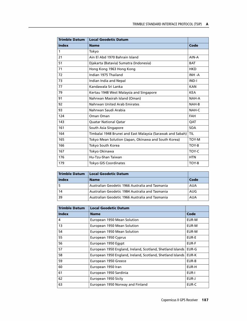
TRIMBLE STANDARD INTERFACE PROTOCOL (TSIP) A
Trimble Datum Local Geodetic Datum
Index Name Code
1 Tokyo
21 Ain El Abd 1970 Bahrain Island AIN-A
51 Djakarta (Batavia) Sumatra (Indonesia) BAT
71 Hong Kong 1963 Hong Kong HKD
72 Indian 1975 Thailand INH -A
73 Indian India and Nepal IND-I
77 Kandawala Sri Lanka KAN
79 Kertau 1948 West Malaysia and Singapore KEA
91 Nahrwan Masirah Island (Oman) NAH-A
92 Nahrwan United Arab Emirates NAH-B
93 Nahrwan Saudi Arabia NAH-C
124 Oman Oman FAH
143 Quatar National Qatar QAT
161 South Asia Singapore SOA
164 Timbalai 1948 Brunei and East Malaysia (Sarawak and Sabah) TIL
165 Tokyo Mean Solution (Japan, Okinawa and South Korea) TOY-M
166 Tokyo South Korea TOY-B
167 Tokyo Okinawa TOY-C
176 Hu-Tzu-Shan Taiwan HTN
179 Tokyo GIS Coordinates TOY-B
Trimble Datum Local Geodetic Datum
Index Name Code
5 Australian Geodetic 1966 Australia and Tasmania AUA
14 Australian Geodetic 1984 Australia and Tasmania AUG
39 Australian Geodetic 1966 Australia and Tasmania AUA
Trimble Datum Local Geodetic Datum
Index Name Code
4 European 1950 Mean Solution EUR-M
13 European 1950 Mean Solution EUR-M
54 European 1950 Mean Solution EUR-M
55 European 1950 Cyprus EUR-E
56 European 1950 Egypt EUR-F
57 European 1950 England, Ireland, Scotland, Shetland Islands EUR-G
58 European 1950 England, Ireland, Scotland, Shetland Islands EUR-K
59 European 1950 Greece EUR-B
60 European 1950 Iran EUR-H
61 European 1950 Sardinia EUR-I
62 European 1950 Sicily EUR-J
63 European 1950 Norway and Finland EUR-C
Copernicus II GPS Receiver 187
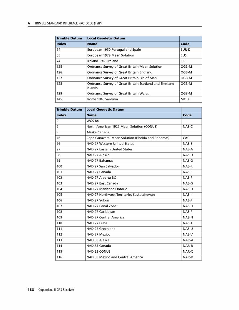
A TRIMBLE STANDARD INTERFACE PROTOCOL (TSIP)
64 European 1950 Portugal and Spain EUR-D
65 European 1979 Mean Solution EUS
74 Ireland 1965 Ireland IRL
125 Ordnance Survey of Great Britain Mean Solution OGB-M
126 Ordnance Survey of Great Britain England OGB-M
127 Ordnance Survey of Great Britain Isle of Man OGB-M
128 Ordnance Survey of Great Britain Scotland and Shetland Islands
OGB-M
129 Ordnance Survey of Great Britain Wales OGB-M
145 Rome 1940 Sardinia MOD
Trimble Datum Local Geodetic Datum
Index Name Code
0 WGS-84
2 North American 1927 Mean Solution (CONUS) NAS-C
3 Alaska Canada
46 Cape Canaveral Mean Solution (Florida and Bahamas) CAC
96 NAD 27 Western United States NAS-B
97 NAD 27 Eastern United States NAS-A
98 NAD 27 Alaska NAS-D
99 NAD 27 Bahamas NAS-Q
100 NAD 27 San Salvador NAS-R
101 NAD 27 Canada NAS-E
102 NAD 27 Alberta BC NAS-F
103 NAD 27 East Canada NAS-G
104 NAD 27 Manitoba Ontario NAS-H
105 NAD 27 Northwest Territories Saskatchewan NAS-I
106 NAD 27 Yukon NAS-J
107 NAD 27 Canal Zone NAS-O
108 NAD 27 Caribbean NAS-P
109 NAD 27 Central America NAS-N
110 NAD 27 Cuba NAS-T
111 NAD 27 Greenland NAS-U
112 NAD 27 Mexico NAS-V
113 NAD 83 Alaska NAR-A
114 NAD 83 Canada NAR-B
115 NAD 83 CONUS NAR-C
116 NAD 83 Mexico and Central America NAR-D
Trimble Datum Local Geodetic Datum
Index Name Code
188 Copernicus II GPS Receiver
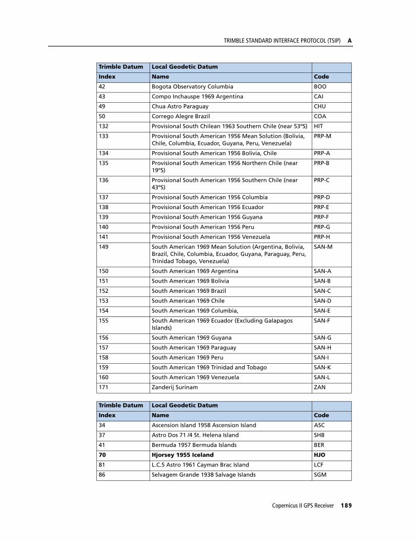
TRIMBLE STANDARD INTERFACE PROTOCOL (TSIP) A
Trimble Datum Local Geodetic Datum
Index Name Code
42 Bogota Observatory Columbia BOO
43 Compo Inchauspe 1969 Argentina CAI
49 Chua Astro Paraguay CHU
50 Corrego Alegre Brazil COA
132 Provisional South Chilean 1963 Southern Chile (near 53ºS) HIT
133 Provisional South American 1956 Mean Solution (Bolivia, Chile, Columbia, Ecuador, Guyana, Peru, Venezuela)
PRP-M
134 Provisional South American 1956 Bolivia, Chile PRP-A
135 Provisional South American 1956 Northern Chile (near 19ºS)
PRP-B
136 Provisional South American 1956 Southern Chile (near 43ºS)
PRP-C
137 Provisional South American 1956 Columbia PRP-D
138 Provisional South American 1956 Ecuador PRP-E
139 Provisional South American 1956 Guyana PRP-F
140 Provisional South American 1956 Peru PRP-G
141 Provisional South American 1956 Venezuela PRP-H
149 South American 1969 Mean Solution (Argentina, Bolivia, Brazil, Chile, Columbia, Ecuador, Guyana, Paraguay, Peru, Trinidad Tobago, Venezuela)
SAN-M
150 South American 1969 Argentina SAN-A
151 South American 1969 Bolivia SAN-B
152 South American 1969 Brazil SAN-C
153 South American 1969 Chile SAN-D
154 South American 1969 Columbia, SAN-E
155 South American 1969 Ecuador (Excluding Galapagos Islands)
SAN-F
156 South American 1969 Guyana SAN-G
157 South American 1969 Paraguay SAN-H
158 South American 1969 Peru SAN-I
159 South American 1969 Trinidad and Tobago SAN-K
160 South American 1969 Venezuela SAN-L
171 Zanderij Surinam ZAN
Trimble Datum Local Geodetic Datum
Index Name Code
34 Ascension Island 1958 Ascension Island ASC
37 Astro Dos 71 /4 St. Helena Island SHB
41 Bermuda 1957 Bermuda Islands BER
70 Hjorsey 1955 Iceland HJO
81 L.C.5 Astro 1961 Cayman Brac Island LCF
86 Selvagem Grande 1938 Salvage Islands SGM
Copernicus II GPS Receiver 189

A TRIMBLE STANDARD INTERFACE PROTOCOL (TSIP)
95 Naparima, BWI Trinidad and Tobago NAP
117 Observatorio Meteorologico 1939 Corvo and Flores Islands (Azores)
FLO
130 Pico De Las Nieves Canary Islands PLN
142 Puerto Rico Puerto Rico and Virgin Islands PUR
144 Qornoq South Greenland QUO
146 Santa Braz Sao Miguel, Santa Maria Islands (Azores) SAO
148 Sapper Hill 1943 East Falkland Islands SAP
162 Porto Santo 1936 Porto Santo and Madera Islands POS
163 Graciosa Base Southwest 1948 Faial, Graciosa, Pico, San Jorg, and Terceira Islands (Azores)
GRA
168 Tristan Astro 1968 Tristan Da Cunha TDC
Trimble Datum Local Geodetic Datum
Index Name Code
22 Anna 1 Astro 1965 Cocos Islands ANO
66 Gan 1970 Republic of Maldives GAA
75 ISTS 073 Astro 1969 Diego Garcia IST
78 Kerguelen Island 1949 Kerguelen Island KEG
80 Reunion Mascarene Island REU
85 Mahe 1971 Mahe Island MIK
Trimble Datum Local Geodetic Datum
Index Name Code
35 Astro Beacon E 1945 Iwo Jima ATF
36 Astro Tern Island (FRIG) 1961 Tern Island TRN
38 Astronomical Station 1952 Marcus Island TRN
40 Bellevue (IGN) Efate Erromango Island IBE
44 Canton Astro1966 Phoenix Island CAO
48 Chatham Island Astro 1971 Chatham Island (New Zealand) CHI
52 Dos 1968 Gizo Island (New Georgia Islands) GIZ
53 Easter Island 1967 Easter Island EAS
67 Geodetic Datum 1948 New Zealand GEO
68 Guam 1963 Guam GUA
69 Gux 1 Astro Guadalcanal Islands DOB
76 Johnstone Island 1961 Johnstone Island JOH
83 Luzon Philippines LUZ-A
84 Luzon Mindanao Island LUZ-B
89 Midway Astro 1961 Midway Islands MID
119 Old Hawaiian Mean Solution OHA-M
120 Old Hawaiian Hawaii OHA-A
Trimble Datum Local Geodetic Datum
Index Name Code
190 Copernicus II GPS Receiver
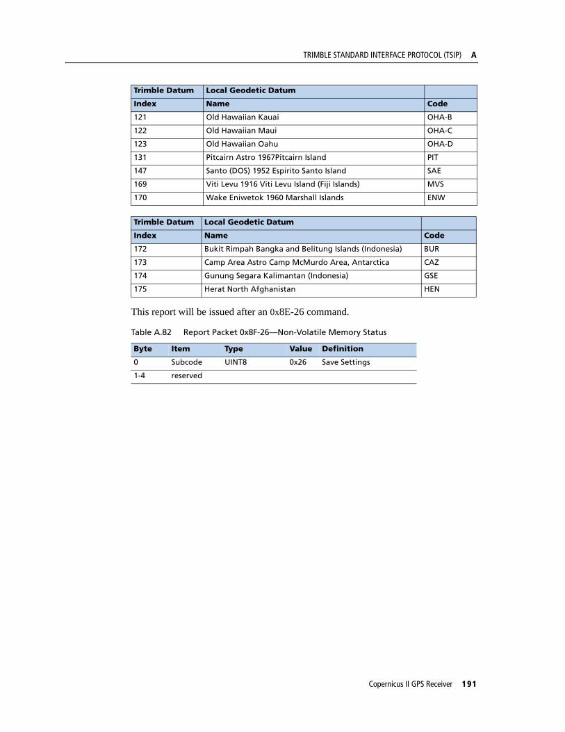
TRIMBLE STANDARD INTERFACE PROTOCOL (TSIP) A
This report will be issued after an 0x8E-26 command.
121 Old Hawaiian Kauai OHA-B
122 Old Hawaiian Maui OHA-C
123 Old Hawaiian Oahu OHA-D
131 Pitcairn Astro 1967Pitcairn Island PIT
147 Santo (DOS) 1952 Espirito Santo Island SAE
169 Viti Levu 1916 Viti Levu Island (Fiji Islands) MVS
170 Wake Eniwetok 1960 Marshall Islands ENW
Trimble Datum Local Geodetic Datum
Index Name Code
172 Bukit Rimpah Bangka and Belitung Islands (Indonesia) BUR
173 Camp Area Astro Camp McMurdo Area, Antarctica CAZ
174 Gunung Segara Kalimantan (Indonesia) GSE
175 Herat North Afghanistan HEN
Table A.82 Report Packet 0x8F-26—Non-Volatile Memory Status
Byte Item Type Value Definition
0 Subcode UINT8 0x26 Save Settings
1-4 reserved
Trimble Datum Local Geodetic Datum
Index Name Code
Copernicus II GPS Receiver 191

A TRIMBLE STANDARD INTERFACE PROTOCOL (TSIP)
192 Copernicus II GPS Receiver

A P P E N D I X
B
TRIMBLE ASCII INTERFACE PROTOCOL (TAIP) BIn this appendix:
Protocol Overview
Message Format
Sample PV Message
Time and Distance Reporting
Latitude and Longitude Conversion
Message Data Strings
Communication Scheme for TAIP
This appendix describes the Trimble ASCII Interface Protocol (TAIP), Trimble’s digital communication interface.
Copernicus II GPS Receiver 193

B TRIMBLE ASCII INTERFACE PROTOCOL (TAIP)
Protocol OverviewTrimble ASCII Interface Protocol (TAIP) is a Trimble-specified digital communication interface based on printable ASCII characters over a serial data link. TAIP was designed specifically for vehicle tracking applications but has become common in a number of other applications because of its ease of use. TAIP supports both scheduled and polled responses.
TAIP messages may be scheduled for output at a user specified rate starting on a given epoch from top of the hour. For communication robustness, the protocol optionally supports checksums on all messages. It also provides the user with the option of tagging all messages with the unit's user specified identification number (ID). This greatly enhances the functional capability of the unit in a network environment. Additionally, given the printable ASCII format of all communication, TAIP is ideal for use with mobile data terminals, modems, and portable computers. Although, receivers incorporating this protocol are shipped from the factory with a specific serial port setting, the port characteristics are fully programmable through TAIP messages.
The Copernicus GPS Receiver supports the following TAIP messages.
Message Description
AL Altitude/Up Velocity
CP Compact Position Solution
ID Identification Number
IP Initial Position
LN Long Navigation Message
PR Protocol
PT Port Characteristic
PV Position/Velocity Solution
RM Reporting Mode
RT Reset Mode
ST Status
TM Time/Date
VR Version Number
194 Copernicus II GPS Receiver
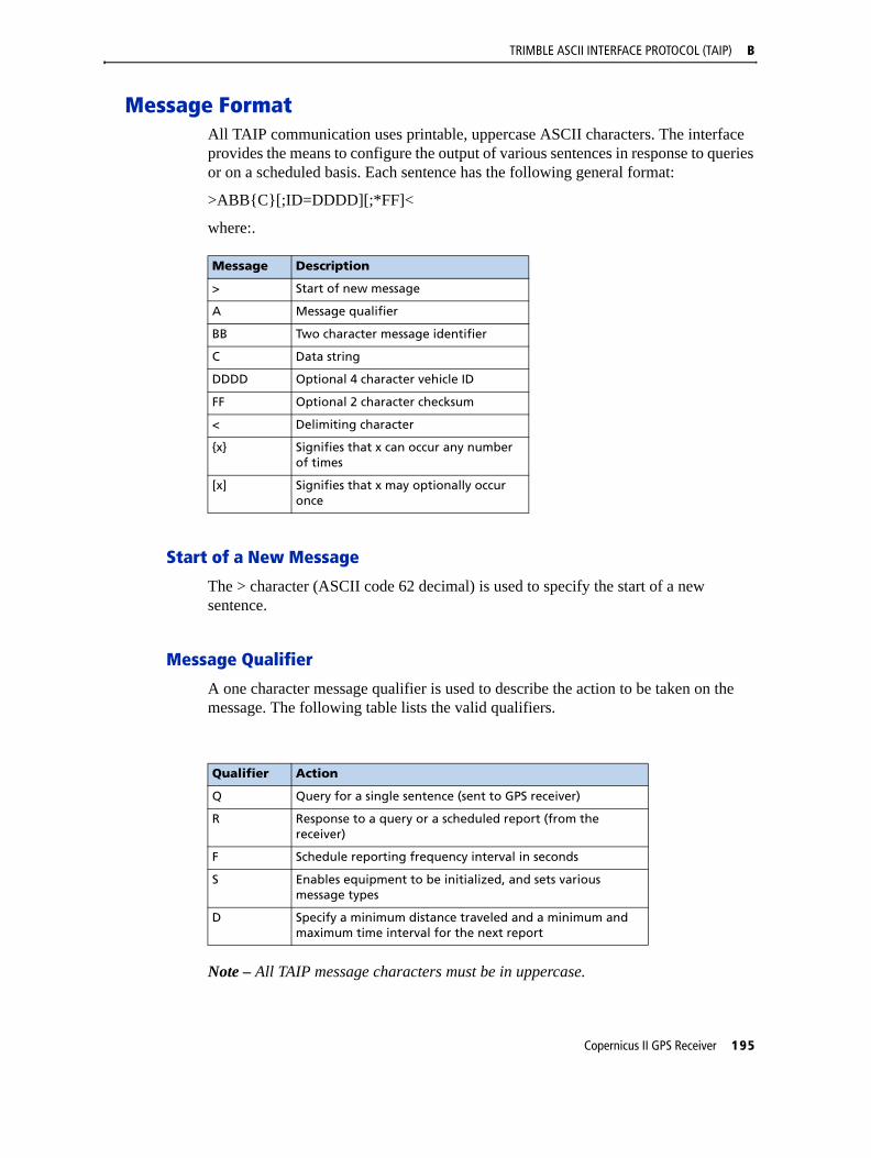
TRIMBLE ASCII INTERFACE PROTOCOL (TAIP) B
Message FormatAll TAIP communication uses printable, uppercase ASCII characters. The interface provides the means to configure the output of various sentences in response to queries or on a scheduled basis. Each sentence has the following general format:
>ABB{C}[;ID=DDDD][;*FF]<
where:.
Start of a New Message
The > character (ASCII code 62 decimal) is used to specify the start of a new sentence.
Message Qualifier
A one character message qualifier is used to describe the action to be taken on the message. The following table lists the valid qualifiers.
Note – All TAIP message characters must be in uppercase.
Message Description
> Start of new message
A Message qualifier
BB Two character message identifier
C Data string
DDDD Optional 4 character vehicle ID
FF Optional 2 character checksum
< Delimiting character
{x} Signifies that x can occur any number of times
[x] Signifies that x may optionally occur once
Qualifier Action
Q Query for a single sentence (sent to GPS receiver)
R Response to a query or a scheduled report (from the receiver)
F Schedule reporting frequency interval in seconds
S Enables equipment to be initialized, and sets various message types
D Specify a minimum distance traveled and a minimum and maximum time interval for the next report
Copernicus II GPS Receiver 195

B TRIMBLE ASCII INTERFACE PROTOCOL (TAIP)
Message Identifier
A unique two character message identifier consisting of alphabetical characters is used to identify type messages. For example: PR for Protocol or VR for Version Number.
Data String
The format and length of a data string is dictated by the message qualifier and the message identifier. The data string may contain any printable ASCII character with the exception of the >, <, and ; characters. Detailed descriptions of each message format are provided in the specific message sections of this Appendix. Most messages are length sensitive and unless otherwise specified, field separators, including spaces are not used.
Vehicle ID
A vehicle identification (ID) may optionally be used in all the communications with the receiver. Each receiver in the fleet may be assigned a four character alpha-numeric ID and be forced to output that ID in all messages. The default is: ID set to 0000 and the ID Flag set to F (false). The receiver will check all incoming messages for ID. If no ID is specified, the receiver will accept the message. If the ID is included in messages but does not compare with the ID previously set, the message will be ignored. This applies even when the ID Flag is turned off.
Checksum
The checksum field provides for an optional two digit hex checksum value, which is computed as XOR of all characters from the beginning of the sentence up to and including the * character. If provided, the checksum is always the last element of the sentence before the message delimiter. The default mode of operation is to include checksum in sentences. The use of checksums can help in instances where the communication channel is noisy.
Example
The following message used to set the vehicle ID flag includes checksum.
>SRM;ID_FLAG=T;*6F<
In this example, the checksum (6F) was generated by XOR'ing the ASCII codes for > and S then XOR'ing that result with the ASCII code for R and so forth, up to and including the * character.
Message Delimiter
The < character signifies end of a sentence and is used as the message delimiter.
196 Copernicus II GPS Receiver
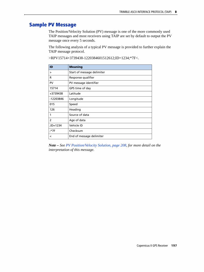
TRIMBLE ASCII INTERFACE PROTOCOL (TAIP) B
Sample PV MessageThe Position/Velocity Solution (PV) message is one of the more commonly used TAIP messages and most receivers using TAIP are set by default to output the PV message once every 5 seconds.
The following analysis of a typical PV message is provided to further explain the TAIP message protocol.
>RPV15714+3739438-1220384601512612;ID=1234;*7F<.
Note – See PV Position/Velocity Solution, page 208, for more detail on the interpretation of this message.
ID Meaning
> Start of message delimiter
R Response qualifier
PV PV message identifier
15714 GPS time of day
+3739438 Latitude
-12203846 Longitude
015 Speed
126 Heading
1 Source of data
2 Age of data
;ID=1234 Vehicle ID
;*7F Checksum
< End of message delimiter
Copernicus II GPS Receiver 197

B TRIMBLE ASCII INTERFACE PROTOCOL (TAIP)
Time and Distance ReportingThe ’D’ message qualifier allows you to specify a minimum distance traveled as well as a minimum and maximum time interval for the next report. Units that are stationed at a fixed location can be programmed to report only when the unit moves “off station” or after a certain elapsed time since last report, but no more often than the specified minimum time interval.
The message format used with the ’D’ qualifier is shown below:
>DAABBBBCCCCEEEEFFFF[;ID=GGGG][;*HH]<
The distance ‘D’ in the message refers to the radial distance. A message would be issued if the receiver has moved farther than a radius of ‘D’ away from where it was previously reported. If the accumulated distance traveled is longer than ‘D’ but the final location is still within the radius of ‘D’ (e.g. circling many times around a closed perimeter of radius smaller than ‘D’), then no message would be issued.
Note – If BBBB = 0, then the message output is disabled. If FFFF = 0, maximum time feature is disabled (the unit will only report if current position is greater than or equal to the delta distance specified in EEEE).
Example
When the message: >DPV0030000505000900;ID=0105< is sent to the GPS receiver, it specifies that vehicle number 105 (GGGG = 0105) is to report the Position Velocity message (AA = PV) whenever its current position differs from the previously reported position by at least 500 meters (EEEE = 0500), but no more often than every 30 seconds (BBBB = 0030) or less often than every 15 minutes (FFFF = 0900 seconds). The minimum and maximum time-out reports are to be issued with a 5 second offset (CCCC = 0005) from the top of the hour. The optional checksum was not used in this example. The square brackets, [...], shown in the format description above are used to indicate optional data. The brackets themselves are never included in the actual TAIP message string.
ID Meaning
> Start of message delimiter
D Distance message qualifier
AA Message to report (i.e. PV means Position Velocity message)
BBBB Minimum time (seconds) interval between reports (Tinterval)
CCCC Report epoch (number of seconds from top of the hour)
EEEE Delta distance (meters) from last reported distance
FFFF Maximum time (seconds) interval between reports (Tmax)
GGGG Optional vehicle identification number (user selected)
HH Optional checksum
< End of message delimiter
198 Copernicus II GPS Receiver

TRIMBLE ASCII INTERFACE PROTOCOL (TAIP) B
Latitude and Longitude ConversionThe TAIP protocol reports latitude as positive north decimal degrees and longitude as positive east decimal degrees, using the WGS-84 datum. For your application, you may wish to convert to degrees, minutes and seconds. The following example illustrates the conversion of decimal degrees to degrees, minutes and seconds.
Example
Given latitude and longitude in decimal degrees,
Latitude: +37.39438o
Longitude: -122.03846o
Convert latitude by multiplying the decimal fraction of degrees by 60 to convert to minutes,
0.39438 x 60 = 23.6628 minutes
Retain the integer (23) portion as the minutes then multiply the decimal fraction by 60 to convert to seconds,
0.6628 x 60 = 39.768 seconds
Since the sign of the latitude in this example is positive the result is,
Latitude: N 37o 23' 39.77"
The longitude is converted in the same fashion,
Longitude: W 122o 02' 18.46"
Note – At the earth's equator, one degree of latitude and longitude represents 68.7 miles; therefore, 0.00001 degrees represents approximately 3.6 feet or 1.1 meters. Each second represents approximately 100.76 ft. (30.7 m).
Copernicus II GPS Receiver 199
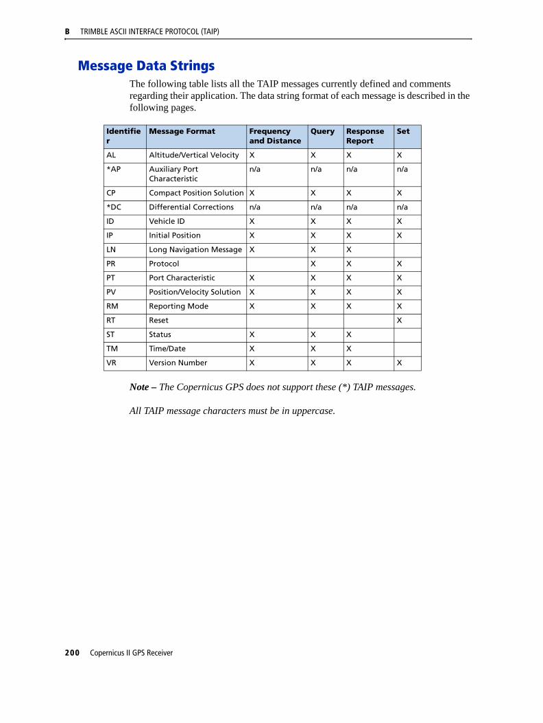
B TRIMBLE ASCII INTERFACE PROTOCOL (TAIP)
Message Data StringsThe following table lists all the TAIP messages currently defined and comments regarding their application. The data string format of each message is described in the following pages.
Note – The Copernicus GPS does not support these (*) TAIP messages.
All TAIP message characters must be in uppercase.
Identifier
Message Format Frequency and Distance
Query ResponseReport
Set
AL Altitude/Vertical Velocity X X X X
*AP Auxiliary Port Characteristic
n/a n/a n/a n/a
CP Compact Position Solution X X X X
*DC Differential Corrections n/a n/a n/a n/a
ID Vehicle ID X X X X
IP Initial Position X X X X
LN Long Navigation Message X X X
PR Protocol X X X
PT Port Characteristic X X X X
PV Position/Velocity Solution X X X X
RM Reporting Mode X X X X
RT Reset X
ST Status X X X
TM Time/Date X X X
VR Version Number X X X X
200 Copernicus II GPS Receiver
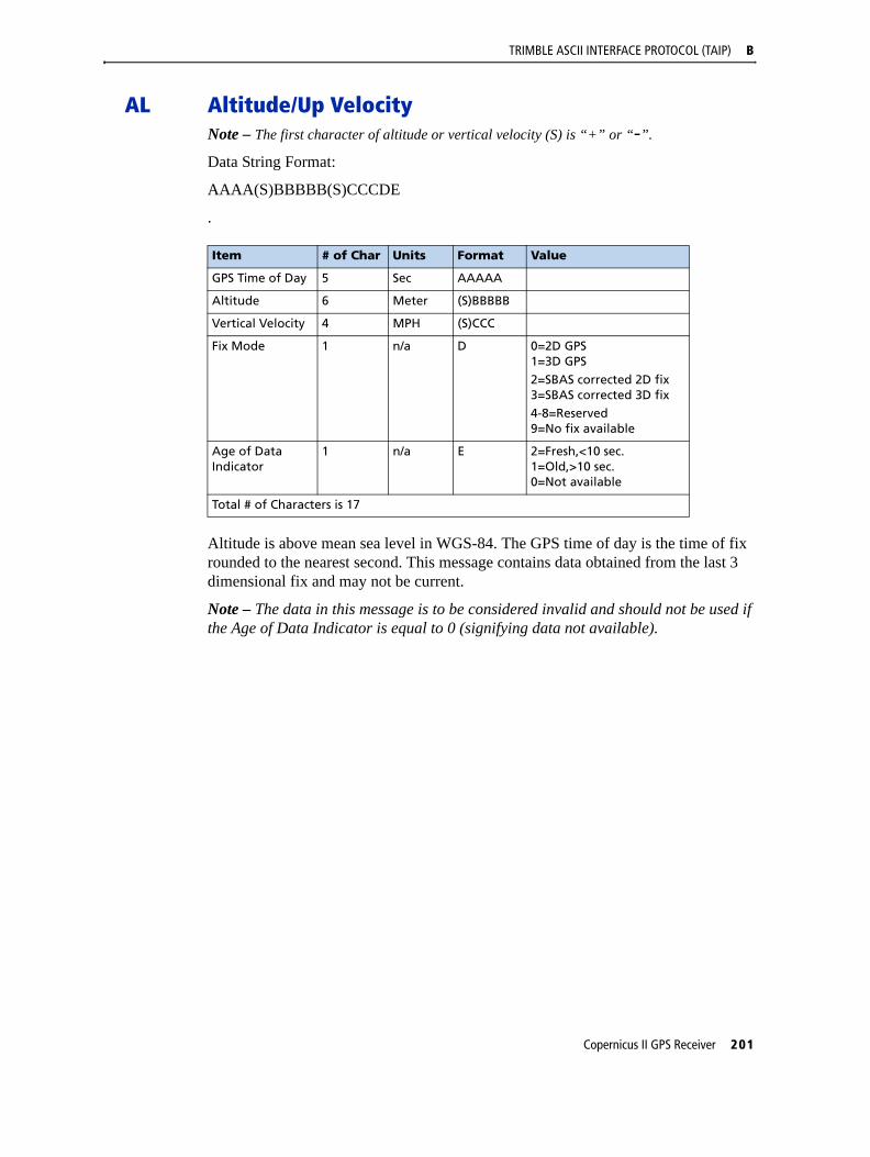
TRIMBLE ASCII INTERFACE PROTOCOL (TAIP) B
AL Altitude/Up VelocityNote – The first character of altitude or vertical velocity (S) is “+” or “-”.
Data String Format:
AAAA(S)BBBBB(S)CCCDE
.
Altitude is above mean sea level in WGS-84. The GPS time of day is the time of fix rounded to the nearest second. This message contains data obtained from the last 3 dimensional fix and may not be current.
Note – The data in this message is to be considered invalid and should not be used if the Age of Data Indicator is equal to 0 (signifying data not available).
Item # of Char Units Format Value
GPS Time of Day 5 Sec AAAAA
Altitude 6 Meter (S)BBBBB
Vertical Velocity 4 MPH (S)CCC
Fix Mode 1 n/a D 0=2D GPS1=3D GPS
2=SBAS corrected 2D fix3=SBAS corrected 3D fix4-8=Reserved9=No fix available
Age of Data Indicator
1 n/a E 2=Fresh,<10 sec.1=Old,>10 sec.0=Not available
Total # of Characters is 17
Copernicus II GPS Receiver 201

B TRIMBLE ASCII INTERFACE PROTOCOL (TAIP)
CP Compact Position SolutionNote – The first character of latitude or longitude “(S)” is “+” or “-”.
Data String Format:
AAAAA(S)BBCCCC(S)DDDEEEEFG
Position is in latitude (positive north) and longitude (positive east) WGS-84. The GPS time of day is the time of fix rounded to the nearest second.
Note – The data in this message is to be considered invalid and should not be used, if the Age of Data Indicator is equal to 0 (signifying that data is not available).
Item # of Char Units Format Value
GPS Time of Day 5 Sec AAAAA
Latitude 7 Deg (S)BBCCCC
Longitude 8 Deg (S)DDDEEEE
Fix Mode 1 n/a F 0=2D GPS1=3D GPS2=SBAS corrected 2D fix3=SBAS corrected 3D fix4-8=Reserved9=No fix available
Age of Data Indicator
1 n/a G 2=Fresh,<10 sec.1=Old,>10 sec.0=Not available
Total number of characters is 22
202 Copernicus II GPS Receiver

TRIMBLE ASCII INTERFACE PROTOCOL (TAIP) B
ID Identification NumberData String Format:
AAAA
This message is used to report or set the vehicle's (or receiver’s) unique, four character, alpha-numeric, user assigned ID. The default at cold start is 0000.
Example
The following message will set the vehicle ID to 101.
>SID0101<
The following is simply a response to a query for vehicle ID.
>RID0101<
Note – The receiver will always check incoming messages for ID and compare with the vehicle ID set in the receiver’s memory. If no ID is included in the message, the receiver will assume a match and accept the message. If the message sent to the receiver does contain a vehicle ID but that ID does not match the ID previously set in the receiver, the message will be ignored. This process is followed even when the ID_Flag is turned off (refer to the message RM).
Item # of Char Units Format
Vehicle ID 4 n/a AAAA
Total number of characters is 4
Copernicus II GPS Receiver 203
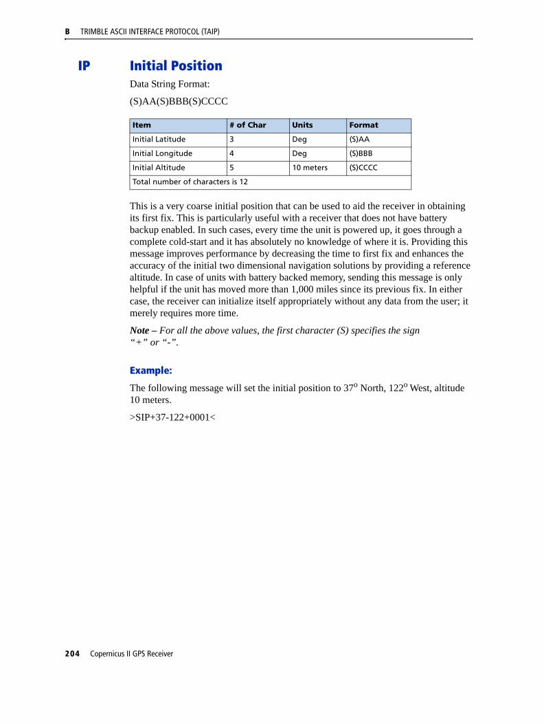
B TRIMBLE ASCII INTERFACE PROTOCOL (TAIP)
IP Initial PositionData String Format:
(S)AA(S)BBB(S)CCCC
This is a very coarse initial position that can be used to aid the receiver in obtaining its first fix. This is particularly useful with a receiver that does not have battery backup enabled. In such cases, every time the unit is powered up, it goes through a complete cold-start and it has absolutely no knowledge of where it is. Providing this message improves performance by decreasing the time to first fix and enhances the accuracy of the initial two dimensional navigation solutions by providing a reference altitude. In case of units with battery backed memory, sending this message is only helpful if the unit has moved more than 1,000 miles since its previous fix. In either case, the receiver can initialize itself appropriately without any data from the user; it merely requires more time.
Note – For all the above values, the first character (S) specifies the sign “+” or “-”.
Example:
The following message will set the initial position to 37o North, 122o West, altitude 10 meters.
>SIP+37-122+0001<
Item # of Char Units Format
Initial Latitude 3 Deg (S)AA
Initial Longitude 4 Deg (S)BBB
Initial Altitude 5 10 meters (S)CCCC
Total number of characters is 12
204 Copernicus II GPS Receiver

TRIMBLE ASCII INTERFACE PROTOCOL (TAIP) B
LN Long Navigation MessageNote – The first character of latitude, longitude, altitude or vertical speed (S) is“+” or “-”.
Data String Format:
AAAAA.BBB(S)CCDDDDDDD(S)EEEFFFFFFF(S)GGGGGGHHIIIJ(S)KKKLMMMNOOPPQQPPQQ...PPQQRRRRRRRRRRXT
Note – At least 2 satellites are required to get the LN Message.
Position is in degrees, minutes, and decimal minutes. Latitude is (positive north); longitude is (positive east) WGS-84. Heading is in degrees from True North increasing eastwards. The GPS time of day is the time of fix rounded to the nearest second.
Note – The data in this message is to be considered invalid and should not be used if the Age of Data Indicator is equal to 0 (signifying data not available).
Item # of Char
Units Format Value
GPS Time of Day 8 Sec AAAAA.BBB
Latitude 10 Deg (S)CC.DDDDDDD
Longitude 11 Deg (S)EEE.FFFFFFF
Altitude above MSL
9 Ft (S)GGGGGG.HH
Horizontal speed 4 MPH lll.J
Vertical speed 5 MPH (S)KKK.L
Heading 4 Deg MMM.N
Number of SVs used
2 n/a OO
SV ID (see note) 2 n/a PP
IODE (see note) 2 n/a QQ
Reserved 10 n/a RRRRRRRRRR
Fix Mode 1 n/a X 0=2D GPS1=3D GPS2=SBAS corrected 2D fix3=SBAS corrected 3D fix
4-8=Reserved9=No fix available
Age of Data indicator
1 n/a T 2=fresh,<10 sec.1=old,>10 sec.0=not available
Total number of characters is 65 + 4x (number of SVs used)
Copernicus II GPS Receiver 205
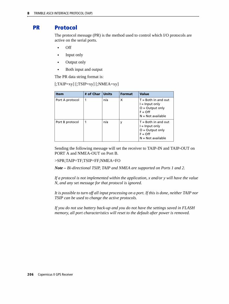
B TRIMBLE ASCII INTERFACE PROTOCOL (TAIP)
PR ProtocolThe protocol message (PR) is the method used to control which I/O protocols are active on the serial ports.
• Off
• Input only
• Output only
• Both input and output
The PR data string format is:
[;TAIP=xy] [;TSIP=xy] [;NMEA=xy]
Sending the following message will set the receiver to TAIP-IN and TAIP-OUT on PORT A and NMEA-OUT on Port B.
>SPR;TAIP=TF;TSIP=FF;NMEA=FO
Note – Bi-directional TSIP, TAIP and NMEA are supported on Ports 1 and 2.
If a protocol is not implemented within the application, x and/or y will have the value N, and any set message for that protocol is ignored.
It is possible to turn off all input processing on a port. If this is done, neither TAIP nor TSIP can be used to change the active protocols.
If you do not use battery back-up and you do not have the settings saved in FLASH memory, all port characteristics will reset to the default after power is removed.
Item # of Char Units Format Value
Port A protocol 1 n/a X T = Both in and outI = Input onlyO = Output onlyF = OffN = Not available
Port B protocol 1 n/a y T = Both in and outI = Input onlyO = Output onlyF = OffN = Not available
206 Copernicus II GPS Receiver

TRIMBLE ASCII INTERFACE PROTOCOL (TAIP) B
PT Port CharacteristicThis message defines the characteristics for the TAIP port.
Data String Format:
AAAA,B,C,D
Most TAIP using receivers use the following default port characteristics
• 4800 baud
• 8 data bits
• 1 stop bit
• No parity
Note – The characteristics set by this message will be stored in the receiver’s battery backed ram. The Copernicus II GPS receiver family of receivers do not include an internal battery but provide a battery back-up input line that may be used to retain memory when main power is removed.
If you do not use battery back-up, all port characteristics will reset to either the default settings after power is removed, or to the settings previously stored in Flash.
The PT command uses commas between data fields.
Item # of Char Units Format Value
Baud Rate 4 n/a AAAA 4800 - 4800 bps9600 - 9600 bps1920 - 19200 bps
3840 - 38400 bps5760 - 57600 bps1152 - 115200 bps
# of data bits 1 n/a B
# of stop bits 1 n/a C 1
Parity 1 n/a D “N” = None
Total number of characters is 10 (includes commas)
Copernicus II GPS Receiver 207

B TRIMBLE ASCII INTERFACE PROTOCOL (TAIP)
PV Position/Velocity SolutionNote – The first character of latitude or longitude “(S)” is “+” or “-”.
Data String Format:
AAAAA(S)BBCCCCC(S)DDDEEEEEFFFGGGHI
Position is in latitude (positive north) and longitude (positive east) WGS-84. Heading is in degrees from True North increasing eastwards. The GPS time of day is the time of fix rounded to the nearest second.
Note – The data in this message is to be considered invalid and should not be used if the Age of Data Indicator is equal to 0 (signifying data not available).
Item # of Char Units Format Value
GPS Time of Day 5 Sec AAAAA
Latitude 8 Deg (S)BBCCCCC BB=degreesCCCC=decimal degrees
Longitude 8 Deg (S)DDDEEEEE DDD=degreesEEEE=decimal degrees
Speed 3 MPH FFF
Heading 3 Deg. GGG
Fix Mode 1 n/a H 0=2D GPS1=3D GPS2=SBAS corrected 2D fix3=SBAS corrected 3D fix4-8=Reserved9=No fix available
Age of Data Indicator
1 n/a I 2=Fresh,<10 sec.1=Old,>10 sec.0=Not available
Total number of characters is 30
208 Copernicus II GPS Receiver

TRIMBLE ASCII INTERFACE PROTOCOL (TAIP) B
RM Reporting ModeData String Format:
[;ID_FLAG= A][;CS_FLAG= B][;EC_FLAG= C] [;FR_FLAG= D]
[;CR_FLAG=E]
ID Flag determines whether the unit is to include the vehicles ID with each report.
CS Flag determines whether the unit is to include a checksum as part of each message.
EC Flag, when set, will cause the unit to echo back all complete and properly formatted set commands with a response qualifier. This provides an easy way to verify that the unit did in fact receive the intended data.
FR Flag indicates whether the unit is to report messages automatically per their individually scheduled frequency. When set to false, the unit will only respond when queried for a specific message.
CR Flag, when set to True, will cause the receiver to append a carriage return and line feed [CR] [LF] to the end of each message output. This is useful when viewing the un-encoded receiver responses on a terminal or a PC.
The default value at start-up for ID flag and the CR flag is false; the default for CS, EC and FR flags is true.
Example
The following command will turn checksums off and carriage return on:
>SRM;CS_FLAG=F;CR_FLAG=T<
Note – Notice the use of semicolon before the flag name.
Item # of Char Units Format Value
ID Flag 1 n/a A T = TrueF = False
CS Flag 1 n/a B T = TrueF = False
EC Flag 1 n/a C T = TrueF = False
FR Flag 1 n/a D T = TrueF = False
CR Flag 1 n/a E T = TrueF = False
Copernicus II GPS Receiver 209

B TRIMBLE ASCII INTERFACE PROTOCOL (TAIP)
RT Reset ModeData String Format:
Any one of the following data strings can be set. Upper case characters are required.
[ ]
[COLD]
[FACTORY]
[SAVE_CONFIG]
The following procedure is used to change the Copernicus II GPS receiver protocol from TSIP to TAIP:
1. Use the TSIP 0x7E command to setup the TAIP output configuration.
2. Change the protocol to TAIP using TSIP command 0xBC.
3. Save the TAIP settings to Flash memory using the TAIP command >SRTSAVE_CONFIG<.
Message Description
>SRT< Warm Start
>SRTCOLD< Cold Start
>SRTFACTORY< Factory Reset
>SRTSAVE_CONFIG< Save settings to Flash memory
210 Copernicus II GPS Receiver
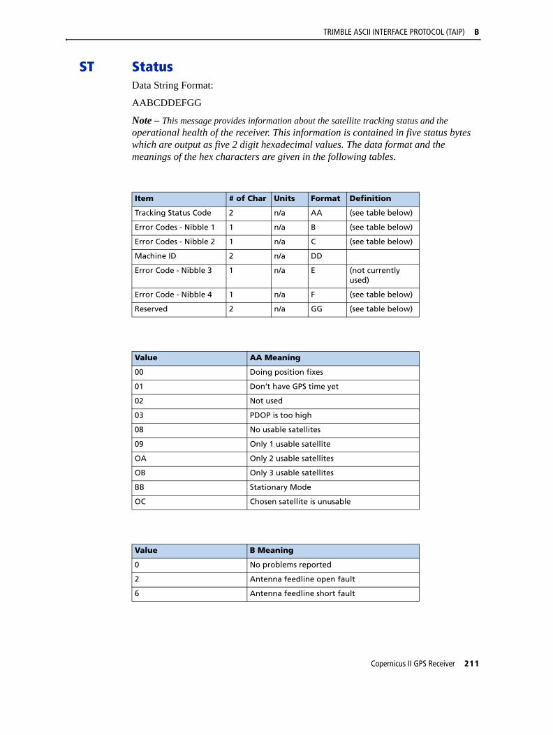
TRIMBLE ASCII INTERFACE PROTOCOL (TAIP) B
ST StatusData String Format:
AABCDDEFGG
Note – This message provides information about the satellite tracking status and the operational health of the receiver. This information is contained in five status bytes which are output as five 2 digit hexadecimal values. The data format and the meanings of the hex characters are given in the following tables.
Item # of Char Units Format Definition
Tracking Status Code 2 n/a AA (see table below)
Error Codes - Nibble 1 1 n/a B (see table below)
Error Codes - Nibble 2 1 n/a C (see table below)
Machine ID 2 n/a DD
Error Code - Nibble 3 1 n/a E (not currently used)
Error Code - Nibble 4 1 n/a F (see table below)
Reserved 2 n/a GG (see table below)
Value AA Meaning
00 Doing position fixes
01 Don’t have GPS time yet
02 Not used
03 PDOP is too high
08 No usable satellites
09 Only 1 usable satellite
OA Only 2 usable satellites
OB Only 3 usable satellites
BB Stationary Mode
OC Chosen satellite is unusable
Value B Meaning
0 No problems reported
2 Antenna feedline open fault
6 Antenna feedline short fault
Copernicus II GPS Receiver 211

B TRIMBLE ASCII INTERFACE PROTOCOL (TAIP)
Note – After the status is detected, this bit remains set until the receiver is reset.
Value C Meaning
0 No problems reported
1 Battery-back-up failed; RAM not available at power-up (see Note below).
Value DD Meaning
DD Displays the machine ID
Value E Meaning
Not used Not used
Value F Meaning
0 No problems reported
2 RTC not available at power-up (see Note below)
8 Stored almanac not complete and current
A RTC not available; stored almanac not complete and current
Value GG Meaning
Not used Reserved
212 Copernicus II GPS Receiver

TRIMBLE ASCII INTERFACE PROTOCOL (TAIP) B
TM Time/DateData String Format:
AABBCCDDDEEFFGGGGHHIJJKLLLLL
.
This message outputs the time and date as computed by the GPS receiver. The time is most accurate when the unit is doing fixes. It is less accurate but still usable when the unit is not doing fixes but the Number of Usable SVs is one or more. If the GPS UTC offset is available, the time will be in UTC. If not, the time will be in GPS.
Note – GPS UTC Time Offset is the difference between GPS and UTC time standards in seconds. The UTC time of Day is only valid if the GPS UTC Offset Valid Flag is indicating valid.
Note – The TM message is not supported under the Set qualifier.
Item # of Char Units Format Value
Hours 2 Hour AA
Minutes 2 Min BB
Seconds 5 Sec CC.DDD
Date; Day 2 Day EE
Date; Month 2 Month FF
Date; Year 4 Year GGGG
GPS UTC Time Offset
2 Sec HH
Fix Mode 1 n/a f 0=2D GPS1=3D GPS2=SBAS corrected 2D fix3=SBAS corrected 3D fix4-8=Reserved9=No fix available
Number of usable satellites
2 n/a JJ
GPS UTC Offset flag
1 n/a K (1 = valid)(0 = invalid)
Reserved 5 n/a LLLLL
Total number of characters is 28
Copernicus II GPS Receiver 213
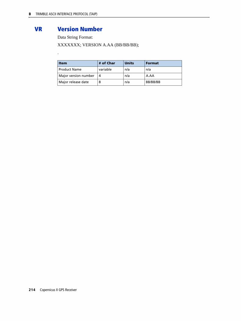
B TRIMBLE ASCII INTERFACE PROTOCOL (TAIP)
VR Version NumberData String Format:
XXXXXXX; VERSION A.AA (BB/BB/BB);
.
Item # of Char Units Format
Product Name variable n/a n/a
Major version number 4 n/a A.AA
Major release date 8 n/a BB/BB/BB
214 Copernicus II GPS Receiver

TRIMBLE ASCII INTERFACE PROTOCOL (TAIP) B
X1 Extended StatusThe Copernicus II GPS receiver does not support this message.
Copernicus II GPS Receiver 215

B TRIMBLE ASCII INTERFACE PROTOCOL (TAIP)
Communication Scheme for TAIPCommunication with the unit takes place in four different ways. Message qualifiers are used to differentiate between these.
Query for Single Sentence
The query (Q) message qualifier is used to query the GPS receiver to respond immediately with a specific message. The format is:
>QAA[;ID=BBBB][;*CC]<
where AA is the requested message identifier. Messages supported by this qualifier are
AL, AP, CP, ID, IP, LN, PT, PV, RM, ST, TM, and VR.
Scheduled Reporting Frequency Interval
The scheduled reporting frequency interval (F) message qualifier is used to tell the unit how often and when to report a specific message. The format is:
>FAABBBBCCCC[;ID=DDDD][;*FF]<
where sending this sentence tells the unit to report message specified by the two digit identifier AA at the time interval of BBBB seconds with time epoch at CCCC seconds from top of the hour. Specifying time interval of 0000 stops scheduled reporting of the message. The default is 0000 time interval for all messages except PV. The output frequency for PV at cold-start is set at once every five seconds, zero seconds from top of the hour. Messages supported by this qualifier are AL, AP, CP, ID, IP, LN, PT, PV, RM, ST, TM, and VR.
Note – The Copernicus GPS Receiver does not support the AP TAIP message.
The data specified by this qualifier is the timing of the message output and may be different from the time tag of the data in the message.
The Response to Query or Scheduled Report
The response (R) qualifier carry various types of data between the unit and the user equipment. The format is:
>RAA[{B}][;ID=CCCC][;*DD]<
where AA is the two character message identifier and {B} specifies the data string within the message. For the format of {B}, please refer to the message definitions in the previous section. Messages supported by the response qualifier are AL, AP, CP, ID, IP, LN, PT, PV, RM, ST, TM, and VR.
Note – The Copernicus GPS does not support the AP TAIP message.
216 Copernicus II GPS Receiver
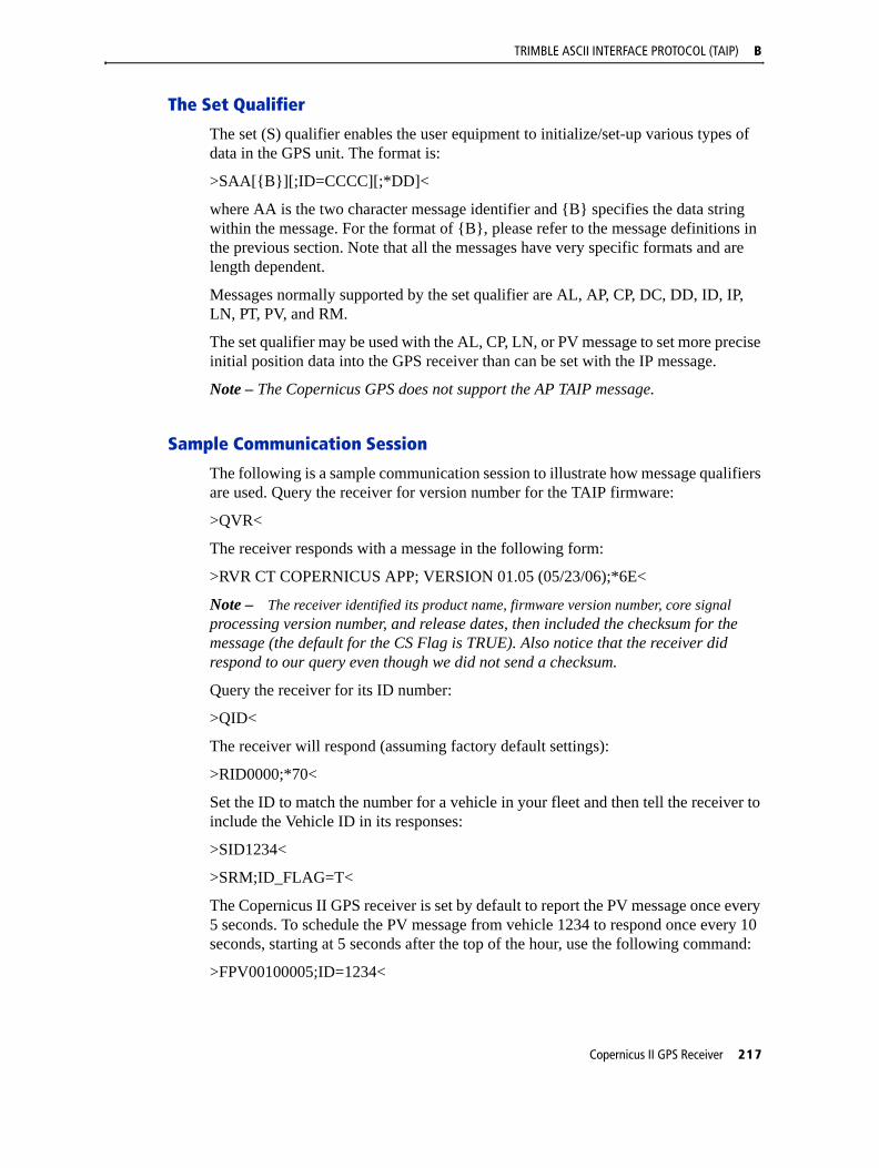
TRIMBLE ASCII INTERFACE PROTOCOL (TAIP) B
The Set Qualifier
The set (S) qualifier enables the user equipment to initialize/set-up various types of data in the GPS unit. The format is:
>SAA[{B}][;ID=CCCC][;*DD]<
where AA is the two character message identifier and {B} specifies the data string within the message. For the format of {B}, please refer to the message definitions in the previous section. Note that all the messages have very specific formats and are length dependent.
Messages normally supported by the set qualifier are AL, AP, CP, DC, DD, ID, IP, LN, PT, PV, and RM.
The set qualifier may be used with the AL, CP, LN, or PV message to set more precise initial position data into the GPS receiver than can be set with the IP message.
Note – The Copernicus GPS does not support the AP TAIP message.
Sample Communication Session
The following is a sample communication session to illustrate how message qualifiers are used. Query the receiver for version number for the TAIP firmware:
>QVR<
The receiver responds with a message in the following form:
>RVR CT COPERNICUS APP; VERSION 01.05 (05/23/06);*6E<
Note – The receiver identified its product name, firmware version number, core signal processing version number, and release dates, then included the checksum for the message (the default for the CS Flag is TRUE). Also notice that the receiver did respond to our query even though we did not send a checksum.
Query the receiver for its ID number:
>QID<
The receiver will respond (assuming factory default settings):
>RID0000;*70<
Set the ID to match the number for a vehicle in your fleet and then tell the receiver to include the Vehicle ID in its responses:
>SID1234<
>SRM;ID_FLAG=T<
The Copernicus II GPS receiver is set by default to report the PV message once every 5 seconds. To schedule the PV message from vehicle 1234 to respond once every 10 seconds, starting at 5 seconds after the top of the hour, use the following command:
>FPV00100005;ID=1234<
Copernicus II GPS Receiver 217

B TRIMBLE ASCII INTERFACE PROTOCOL (TAIP)
The receiver will check the ID included in the message for a match with its own and then reschedule the PV message. At the next scheduled time, the receiver will respond with:
>RPV15714+3739438-1220384601512612;ID=1234;*7F<
Note – The Copernicus GPS does not support the AP TAIP message.
The time given in the message is the time of the last GPS fix (04:21:54 GPS), not necessarily the time of the message response. If the time of last fix is 10 or more seconds old, the age flag will be set to 1.
218 Copernicus II GPS Receiver

A P P E N D I X
C
NMEA 0183 CIn this appendix:
Overview
The NMEA 0183 Communication Interface
NMEA 0183 Message Format
Field Definitions
Checksum
Exception Behavior
NMEA 0183 Message Options
NMEA 0183 Message Formats
This appendix provides a brief overview of the NMEA 0183 protocol, and describes both the standard and optional messages offered by the Copernicus II GPS Receiver.
Copernicus II GPS Receiver 219

C NMEA 0183
OverviewNMEA 0183 is a simple, yet comprehensive ASCII protocol which defines both the communication interface and the data format. The NMEA 0183 protocol was originally established to allow marine navigation equipment to share information. Since it is a well established industry standard, NMEA 0183 has also gained popularity for use in applications other than marine electronics. The Copernicus II GPS receiver supports the latest release of NMEA 0183, Version 3.0 (July 1, 2000). The primary change in release 3.0 is the addition of the mode indicators in the GLL, RMC, and VTG messages. In addition, the Copernicus II GPS receiver supports bi-directional NMEA with the description of the Trimble proprietary NMEA sentences found in this Appendix
For those applications requiring output only from the GPS receiver, the standard NMEA 0183 sentences are a popular choice. Many standard application packages support the standard NMEA output messages. With the addition of the Trimble proprietary bi-directional NMEA, the user can now gain complete control of the Copernicus II GPS module including configuration and program control.
The standard NMEA output only messages are: GGA, GLL, GSA, GSV, RMC, VTG, and ZDA.
NMEA National Office7 Riggs Ave., Severna Park, MD [email protected]
220 Copernicus II GPS Receiver

NMEA 0183 C
The NMEA 0183 Communication InterfaceThe Copernicus II GPS receiver can be configured for NMEA on either port A or port B, at any baud rate. Below are the default NMEA characteristics for Port B of the Copernicus II GPS receiver.
Table C.1 Signal Characteristics
NMEA 0183 Message FormatThe NMEA 0183 protocol covers a broad array of navigation data. The entire protocol encompasses over 50 messages, but only a sub-set of these messages apply to a GPS receiver like the Copernicus II GPS Receiver. The NMEA message structure is described below.
$IDMSG,D1,D2,D3,D4,.......,Dn*CS[CR][LF]
“$” The “$” signifies the start of a message.ID The identification is a two letter mnemonic which describes the
source of the navigation information. The GP identification signifies a GPS source.
MSG The message identification is a three letter mnemonic which describes the message content and the number and order of the data fields.
“,” Commas serve as delimiters for the data fields.Dn Each message contains multiple data fields (Dn) which are delimited
by commas. The length of the fields can be variable.“*” The asterisk serves as a checksum delimiter. CS The checksum field contains two ASCII characters which indicate
the hexadecimal value of the checksum.[CR][LF] The carriage return [CR] and line feed [LF] combination terminate
the message.
NMEA 0183 standard messages vary in length, but each message is limited to 79 characters or less. This length limitation excludes the “$” and the [CR][LF]. The standard message data field block, including delimiters, is limited to 74 characters or less.
Note – Trimble proprietary messages can exceed 79 characters and the data field block of these messages can exceed 74 characters.
Signal Characteristic NMEA Standard
Baud Rate 4800
Data Bits 8
Parity None (Disabled)
Stop Bits 1
Copernicus II GPS Receiver 221
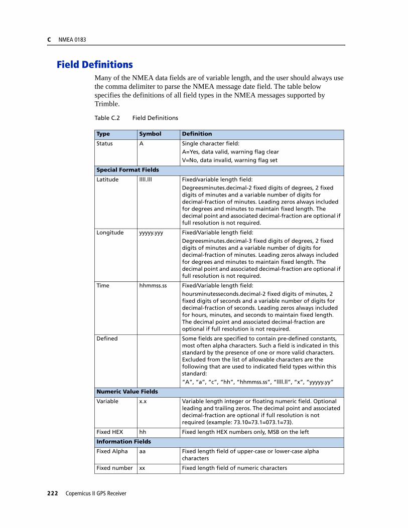
C NMEA 0183
Field DefinitionsMany of the NMEA data fields are of variable length, and the user should always use the comma delimiter to parse the NMEA message date field. The table below specifies the definitions of all field types in the NMEA messages supported by Trimble.
Table C.2 Field Definitions
Type Symbol Definition
Status A Single character field:A=Yes, data valid, warning flag clear
V=No, data invalid, warning flag set
Special Format Fields
Latitude llll.lll Fixed/variable length field:Degreesminutes.decimal-2 fixed digits of degrees, 2 fixed digits of minutes and a variable number of digits for decimal-fraction of minutes. Leading zeros always included for degrees and minutes to maintain fixed length. The decimal point and associated decimal-fraction are optional if full resolution is not required.
Longitude yyyyy.yyy Fixed/Variable length field:
Degreesminutes.decimal-3 fixed digits of degrees, 2 fixed digits of minutes and a variable number of digits for decimal-fraction of minutes. Leading zeros always included for degrees and minutes to maintain fixed length. The decimal point and associated decimal-fraction are optional if full resolution is not required.
Time hhmmss.ss Fixed/Variable length field:
hoursminutesseconds.decimal-2 fixed digits of minutes, 2 fixed digits of seconds and a variable number of digits for decimal-fraction of seconds. Leading zeros always included for hours, minutes, and seconds to maintain fixed length. The decimal point and associated decimal-fraction are optional if full resolution is not required.
Defined Some fields are specified to contain pre-defined constants, most often alpha characters. Such a field is indicated in this standard by the presence of one or more valid characters. Excluded from the list of allowable characters are the following that are used to indicated field types within this standard:
“A”, “a”, “c”, “hh”, “hhmmss.ss”, “llll.ll”, “x”, “yyyyy.yy”
Numeric Value Fields
Variable x.x Variable length integer or floating numeric field. Optional leading and trailing zeros. The decimal point and associated decimal-fraction are optional if full resolution is not required (example: 73.10=73.1=073.1=73).
Fixed HEX hh Fixed length HEX numbers only, MSB on the left
Information Fields
Fixed Alpha aa Fixed length field of upper-case or lower-case alpha characters
Fixed number xx Fixed length field of numeric characters
222 Copernicus II GPS Receiver

NMEA 0183 C
Note – Spaces are only used in variable text fields.
Units of measure fields are appropriate characters from the Symbol column (see Table C.2), unless a specified unit of measure is indicated.
Fixed length field definitions show the actual number of characters. For example, a field defined to have a fixed length of 5 HEX characters is represented as hhhhh between delimiters in a sentence definition.
Invalid Command Set
In the case that a command is sent with incorrect data, the NMEA sentence $PTNLRxx,V*xx is a generic response.
ChecksumThe checksum is the last field in an NMEA sentence and follows the checksum delimiter character “*”. The checksum is the 8 bit exclusive OR (no start or stop bits) of a character in the sentence including “,” between but not including the “$” and the “*” delimiters. The hexadecimal value of the most significant and less significant 4 bits of the result is converted to two ASCII characters (0-9, A0F (upper case)) for transmission. The most significant character is transmitted first. Examples of the use of the checksum field are:
$GPGLL,5057.970,N,00146,110,E,142451,A*27<CR><LF>
$GPVTG,089,0,T,,,15,2,N,,*7F<CR><LF>
Copernicus II GPS Receiver 223
C NMEA 0183
Exception BehaviorWhen no position fix is available, some of the data fields in the NMEA messages will be blank. A blank field has no characters between the commas. There are three general cases when no fix is available: at power-up without back-up data on SRAM (cold start); at power-up with without back-up data on SRAM (warm start); and when the GPS signal is temporarily blocked. These three cases have different NMEA output behavior in the Copernicus II GPS Receiver. This section describes the behavior for the current product. The specification for this behavior may change in future products.
Power-up with No Back-up Data on SRAM
In this case, no previous fix is available in battery-backed memory. If the output message list and output rate has been customized (using TSIP command packet 0x7A) and stored in Flash memory, then at power-up the receiver will output the messages according to the customized setting. Otherwise, GGA and VTG messages are output every second. Before fixes are available, the message fields will be empty.
Power-up with Back-up Data on SRAM
In this case, a previous fix is available in battery-backed memory at power-up. If the output message list and output rate has been customized (using TSIP command packet 0x7A) and stored in Flash memory, then at power-up the receiver will output the messages according to the customized setting. Otherwise, GGA and VTG messages are output every second. Before fixes are available, the message fields will be empty except for the Time field, assuming the back-up battery power is present so that time can be tracked continuously by the RTC (Real Time Clock).
Interruption of GPS Signal
If the GPS signal is interrupted temporarily, the NMEA will continue to be output according to the user-specified message list and output rate. Position and velocity fields will be blank until the next fix, but most other fields will be filled.
General NMEA Parser Requirements
• When no position fix is available, some of the data fields in the NMEA messages will be blank (i.e., no characters between commas), but selected messages will output every second.
• Trimble varies the number of digits of precision in variable length fields, so customer parsers should be able to handle variable lengths.
• NMEA parsers should be built to be forward-compatible. Future versions of a standard message may have more fields or more choices per field.
• Checksum matching is strongly recommended.
224 Copernicus II GPS Receiver
NMEA 0183 C
• 9600 baud may be required if GSV messages are output.
• When multiple NMEA settings are implemented, save them to Flash memory.
• For GGA, GLL, RMC messages, time is GPS time (not UTC) until leap second parameter is known. There is no way to tell which time your are running in, until the time output suddenly decreases by 14 seconds (or by the current offset).
• For GGA, GLL, RMC messages, if the datum is changed, there is no regular DTM warning of non-WGS-84 datum as required by NMEA 2.1. You must query the datum for this information.
Copernicus II GPS Receiver 225

C NMEA 0183
NMEA 0183 Message OptionsThe Copernicus II GPS Receiver can output any or all of the messages listed in Table C.3 and Table C.4. In its default configuration (as shipped from the factory), the Copernicus II GPS Receiver outputs two messages: GGA and VTG. These messages are output at a 1 second interval with the “GP” ID and checksums. These messages are output at all times during operation, with or without a fix. If a different set of messages has been selected (using Packet 0x7A), and this setting has been stored in Flash memory (using Packet 0x8E-26), the default messages are permanently replaced until the receiver is returned to the factory default settings.
Another methodology for changing NMEA output messages is using the Trimble proprietary NMEA commands listed in Table C.4. Use the NM command to select the NMEA message, and the RT command to store the message in Flash Memory.
Note – The user can configure a custom mix of the messages listed in Table C.4. See command packets 0xBC, 0x7A, and 8E-26 in Appendix A, and the NM and RT command descriptions in this Appendix for details on configuring NMEA output.
C WARNING – If too many messages are specified for output, you may need to increase the unit’s baud rate.
.
Table C.3 Copernicus GPS Receiver NMEA 0183 Messages
Message Description
Default Output
GGA GPS fix data
GLL Geographic position - Latitude/Longitude
GSA GPS DOP and active satellites
GST GPS accuracy information
GSV GPS satellites in view
RMC Recommended minimum specific GPS/Transit data
Default Output
VTG Track made good and ground speed
ZDA Time & Date
226 Copernicus II GPS Receiver

NMEA 0183 C
Table C.4 Copernicus GPS Receiver Proprietary NMEA Messages
Message Description
AH Query or set Almanac Health
AL Query or set almanac data for a specific satellite
AS Query or set almanac status
BA Query and response to antenna status
CR Query or set GPS receiver configuration information
EM Set receiver into Monitor Mode. Set only.
EP Query or set ephemeris data for a specific satellite
FS Query or set GPS receiver acquisition sensitivity
IO Query or set ionosphere data.
KG Set initial position and time info data for to aid navigation startup
NM Query or set NMEA automatic message output control
PS Query or set PPS configuration
PT Query or set serial port configuration
RT Set Reset type (cold
TF Query or set receiver status and position fix information
UT Query or set UTC data
VR Query and response to version information
Copernicus II GPS Receiver 227

C NMEA 0183
NMEA 0183 Message Formats
GGA - GPS Fix Data
The GGA message includes time, position and fix related data for the GPS receiver.
$GPGGA,hhmmss.ss,llll.lllll,a,nnnnn.nnnnn,b,t,uu,v.v,w.w,M,x.x,M,y.y,zzzz*hh <CR><LF>
Table C.5 GGA - GPS Fix Data Message Parameters
Field # Description
1 UTC of Position (when UTC offset has been decoded by the receiver)
2,3 Latitude, N (North) or S (South)
4,5 Longitude, E (East) or W (West)
6 GPS Quality Indicator: 0=invalid fix, 1=GPS fix, no SBAS correction, 2=SBAS corrected fix, 7=the position output is the value last stored in flash
7 Number of Satellites in Use
8 Horizontal Dilution of Precision (HDOP)
9, 10 Antenna Altitude in Meters, M = Meters
11, 12 Geoidal Separation in Meters, M=Meters. Geoidal separation is the difference between the WGS-84 earth ellipsoid and mean-sea-level. “-” = mean-sea-level surface below WG-84 ellipsoid surface
13 Age of Differential GPS Data. Time in seconds since the last Type 1 or 9 Update
14 Differential Reference Station ID (0000 to 1023)
hh Checksum
228 Copernicus II GPS Receiver

NMEA 0183 C
GLL Geographic Position - Latitude/Longitude
The GLL message contains the latitude and longitude of the present vessel position, the time of the position fix and the status.
$GPGLL,llll.lllll,a,yyyyy.yyyyy,a,hhmmss.ss,A,i*hh<CR><LF>
GSA GPS DOP and Active Satellites
The GSA messages indicates the GPS receiver's operating mode and lists the satellites used for navigation and the DOP values of the position solution.
$GPGSA,a,x,xx,xx,xx,xx,xx,xx,xx,xx,xx,xx,xx,xx,x.x,x.x,x.x*hh<CR><LF>
Table C.6 GLL - Geographic Position - Latitude / Longitude Message Parameters
Field Description
1,2 Latitude, N (North) or S (South)
3,4 Longitude, E (East) or W (West)
5 UTC of position (when UTC offset has been decoded by the receiver)
6 Status: A = Valid, V= Invalid
7 Mode Indicator
A=Autonomous ModeD=Differential ModeE=Estimated (dead reckoning) ModeM=Manual Input ModeS=Simulated ModeN-Data Not Valid
hh Checksum
Table C.7 GSA - GPS DOP and Active Satellites Message Parameters
Field # Description
1 Mode: M = Manual, A = Automatic. In manual mode, the receiver is forced to operate in either 2D or 3D mode. In automatic mode, the receiver is allowed to switch between 2D and 3D modes subject to the PDOP and satellite masks.
2 Current Mode: 1 = fix not available, 2 = 2D, 3 = 3D
3 to 14 PRN numbers of the satellites used in the position solution. When less than 12 satellites are used, the unused fields are null
15 Position dilution of precision (PDOP)
16 Horizontal dilution of precision (HDOP)
17 Vertical dilution of precision (VDOP)
hh Checksum
Copernicus II GPS Receiver 229
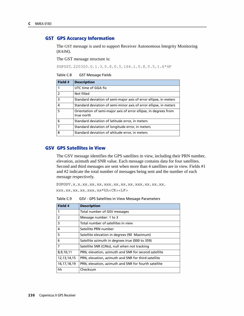
C NMEA 0183
GST GPS Accuracy Information
The GST message is used to support Receiver Autonomous Integrity Monitoring (RAIM).
The GST message structure is:
$GPGST,220320.0,1.3,0.8,0.5,166.1,0.8,0.5,1.6*4F
GSV GPS Satellites in View
The GSV message identifies the GPS satellites in view, including their PRN number, elevation, azimuth and SNR value. Each message contains data for four satellites. Second and third messages are sent when more than 4 satellites are in view. Fields #1 and #2 indicate the total number of messages being sent and the number of each message respectively.
$GPGSV,x,x,xx,xx,xx,xxx,xx,xx,xx,xxx,xx,xx,xx,
xxx,xx,xx,xx,xxx,xx*hh<CR><LF>
Table C.8 GST Message Fields
Field # Description
1 UTC time of GGA fix
2 Not filled
3 Standard deviation of semi-major axis of error ellipse, in meters
4 Standard deviation of semi-minor axis of error ellipse, in meters
5 Orientation of semi-major axis of error ellipse, in degrees from true north
6 Standard deviation of latitude error, in meters
7 Standard deviation of longitude error, in meters
8 Standard deviation of altitude error, in meters
Table C.9 GSV - GPS Satellites in View Message Parameters
Field # Description
1 Total number of GSV messages
2 Message number: 1 to 3
3 Total number of satellites in view
4 Satellite PRN number
5 Satellite elevation in degrees (90 Maximum)
6 Satellite azimuth in degrees true (000 to 359)
7 Satellite SNR (C/No), null when not tracking
8,9,10,11 PRN, elevation, azimuth and SNR for second satellite
12,13,14,15 PRN, elevation, azimuth and SNR for third satellite
16,17,18,19 PRN, elevation, azimuth and SNR for fourth satellite
hh Checksum
230 Copernicus II GPS Receiver
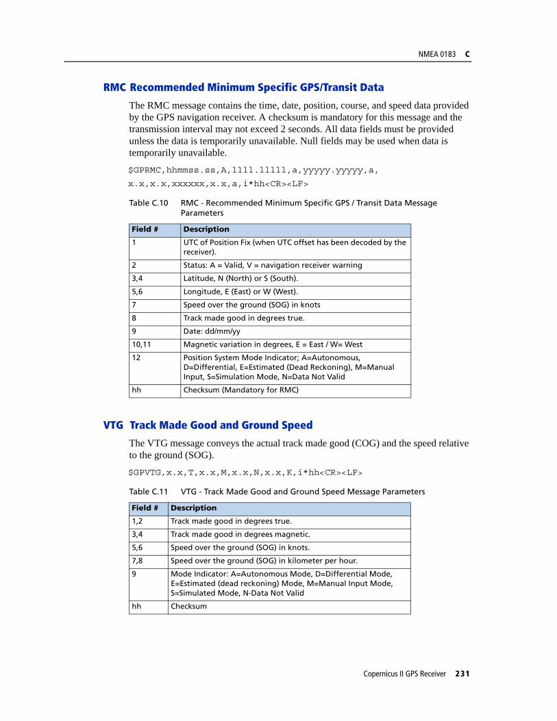
NMEA 0183 C
RMC Recommended Minimum Specific GPS/Transit Data
The RMC message contains the time, date, position, course, and speed data provided by the GPS navigation receiver. A checksum is mandatory for this message and the transmission interval may not exceed 2 seconds. All data fields must be provided unless the data is temporarily unavailable. Null fields may be used when data is temporarily unavailable.
$GPRMC,hhmmss.ss,A,llll.lllll,a,yyyyy.yyyyy,a,
x.x,x.x,xxxxxx,x.x,a,i*hh<CR><LF>
VTG Track Made Good and Ground Speed
The VTG message conveys the actual track made good (COG) and the speed relative to the ground (SOG).
$GPVTG,x.x,T,x.x,M,x.x,N,x.x,K,i*hh<CR><LF>
Table C.10 RMC - Recommended Minimum Specific GPS / Transit Data Message Parameters
Field # Description
1 UTC of Position Fix (when UTC offset has been decoded by the receiver).
2 Status: A = Valid, V = navigation receiver warning
3,4 Latitude, N (North) or S (South).
5,6 Longitude, E (East) or W (West).
7 Speed over the ground (SOG) in knots
8 Track made good in degrees true.
9 Date: dd/mm/yy
10,11 Magnetic variation in degrees, E = East / W= West
12 Position System Mode Indicator; A=Autonomous, D=Differential, E=Estimated (Dead Reckoning), M=Manual Input, S=Simulation Mode, N=Data Not Valid
hh Checksum (Mandatory for RMC)
Table C.11 VTG - Track Made Good and Ground Speed Message Parameters
Field # Description
1,2 Track made good in degrees true.
3,4 Track made good in degrees magnetic.
5,6 Speed over the ground (SOG) in knots.
7,8 Speed over the ground (SOG) in kilometer per hour.
9 Mode Indicator: A=Autonomous Mode, D=Differential Mode, E=Estimated (dead reckoning) Mode, M=Manual Input Mode, S=Simulated Mode, N-Data Not Valid
hh Checksum
Copernicus II GPS Receiver 231
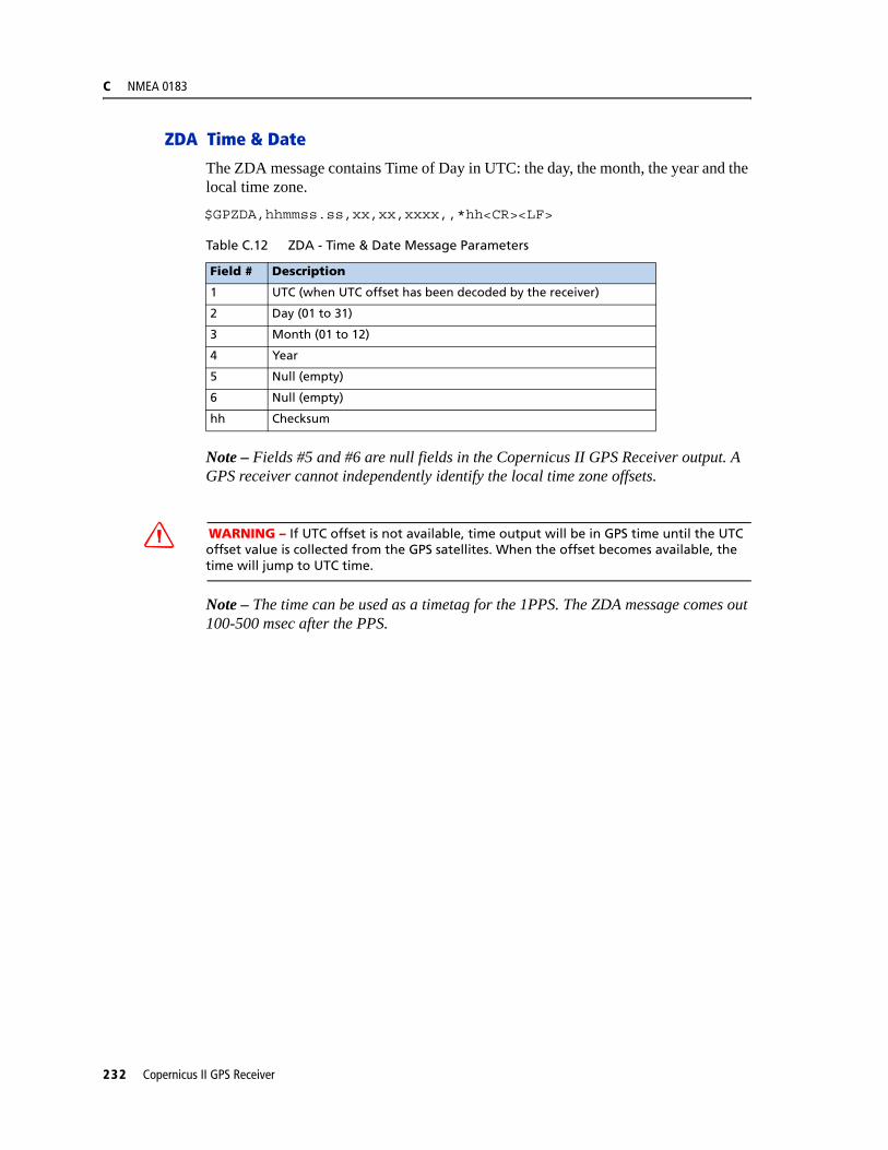
C NMEA 0183
ZDA Time & Date
The ZDA message contains Time of Day in UTC: the day, the month, the year and the local time zone.
$GPZDA,hhmmss.ss,xx,xx,xxxx,,*hh<CR><LF>
Note – Fields #5 and #6 are null fields in the Copernicus II GPS Receiver output. A GPS receiver cannot independently identify the local time zone offsets.
C WARNING – If UTC offset is not available, time output will be in GPS time until the UTC offset value is collected from the GPS satellites. When the offset becomes available, the time will jump to UTC time.
Note – The time can be used as a timetag for the 1PPS. The ZDA message comes out 100-500 msec after the PPS.
Table C.12 ZDA - Time & Date Message Parameters
Field # Description
1 UTC (when UTC offset has been decoded by the receiver)
2 Day (01 to 31)
3 Month (01 to 12)
4 Year
5 Null (empty)
6 Null (empty)
hh Checksum
232 Copernicus II GPS Receiver
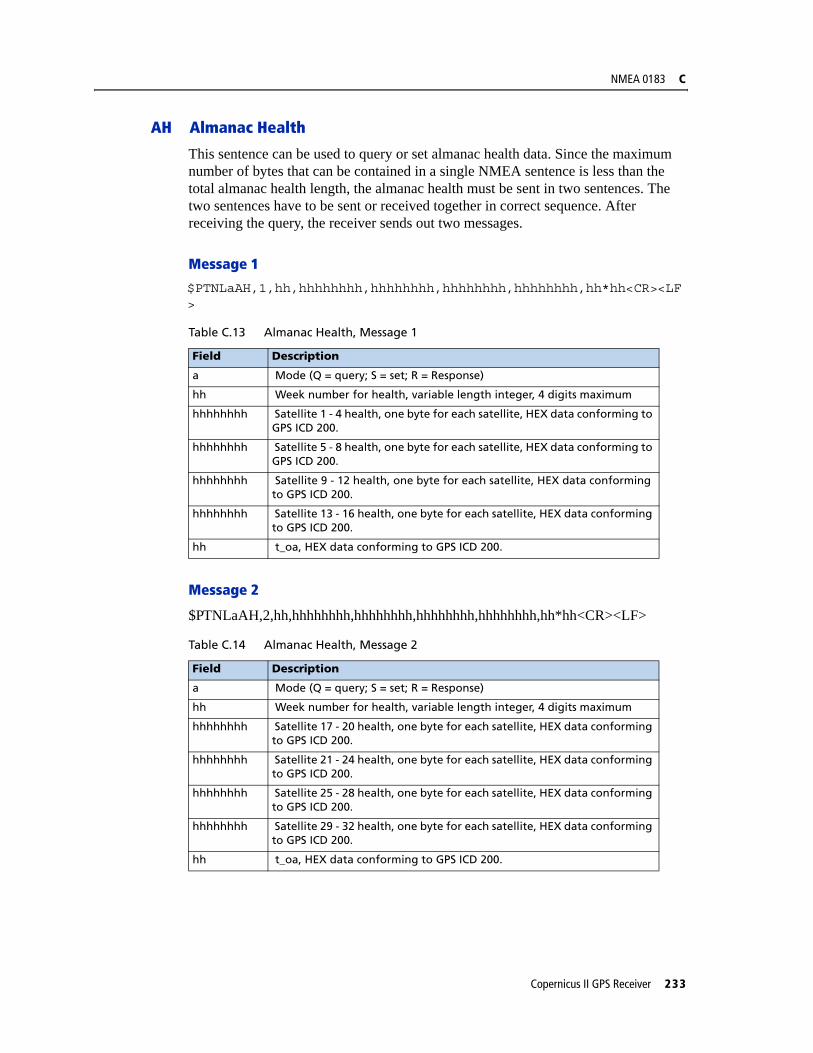
NMEA 0183 C
AH Almanac Health
This sentence can be used to query or set almanac health data. Since the maximum number of bytes that can be contained in a single NMEA sentence is less than the total almanac health length, the almanac health must be sent in two sentences. The two sentences have to be sent or received together in correct sequence. After receiving the query, the receiver sends out two messages.
Message 1
$PTNLaAH,1,hh,hhhhhhhh,hhhhhhhh,hhhhhhhh,hhhhhhhh,hh*hh<CR><LF>
Message 2
$PTNLaAH,2,hh,hhhhhhhh,hhhhhhhh,hhhhhhhh,hhhhhhhh,hh*hh<CR><LF>
Table C.13 Almanac Health, Message 1
Field Description
a Mode (Q = query; S = set; R = Response)
hh Week number for health, variable length integer, 4 digits maximum
hhhhhhhh Satellite 1 - 4 health, one byte for each satellite, HEX data conforming to GPS ICD 200.
hhhhhhhh Satellite 5 - 8 health, one byte for each satellite, HEX data conforming to GPS ICD 200.
hhhhhhhh Satellite 9 - 12 health, one byte for each satellite, HEX data conforming to GPS ICD 200.
hhhhhhhh Satellite 13 - 16 health, one byte for each satellite, HEX data conforming to GPS ICD 200.
hh t_oa, HEX data conforming to GPS ICD 200.
Table C.14 Almanac Health, Message 2
Field Description
a Mode (Q = query; S = set; R = Response)
hh Week number for health, variable length integer, 4 digits maximum
hhhhhhhh Satellite 17 - 20 health, one byte for each satellite, HEX data conforming to GPS ICD 200.
hhhhhhhh Satellite 21 - 24 health, one byte for each satellite, HEX data conforming to GPS ICD 200.
hhhhhhhh Satellite 25 - 28 health, one byte for each satellite, HEX data conforming to GPS ICD 200.
hhhhhhhh Satellite 29 - 32 health, one byte for each satellite, HEX data conforming to GPS ICD 200.
hh t_oa, HEX data conforming to GPS ICD 200.
Copernicus II GPS Receiver 233

C NMEA 0183
AL Almanac Page
This sentence can be used to query or set almanac data for a specific satellite. Following is the query format:
$PTNLQAL,xx*hh<CR><LF>
Following is the set or response format.
$PTNLaAL,xx,x.x,hh,hhhh,hh,hhhh,hhhh,hhhhhh,hhhhhh,hhhhhh,hhhhhh,hhh,hhh*hh<CR><LF>
Table C.15 Almanac Page
Field Description
xx Satellite ID
Table C.16 Almanac Page, Set or Response Format
Field Description
a Mode (S = set; R = Response).
xx Satellite ID, 01-32.
x.x GPS week number, variable length integer, 4 digits maximum.
hh SV health, HEX data conforming to GPS ICD 200.
hhhh Eccentricity, HEX data conforming to GPS ICD 200.
hh t_oa, almanac reference time, HEX data conforming to GPS ICD 200.
hhhh sigma_I,HEX data conforming to GPS ICD 200.
hhhh OMEGADOT, HEX data conforming to GPS ICD 200.
hhhhhh root_a, HEX data conforming to GPS ICD 200.
hhhhhh Omega, HEX data conforming to GPS ICD 200.
hhhhhh Omega_0, HEX data conforming to GPS ICD 200.
hhhhhh M_O, HEX data conforming to GPS ICD 200.
hhh a_fO, HEX data conforming to GPS ICD 200.
hhh a_fl, HEX data conforming to GPS ICD 200.
234 Copernicus II GPS Receiver
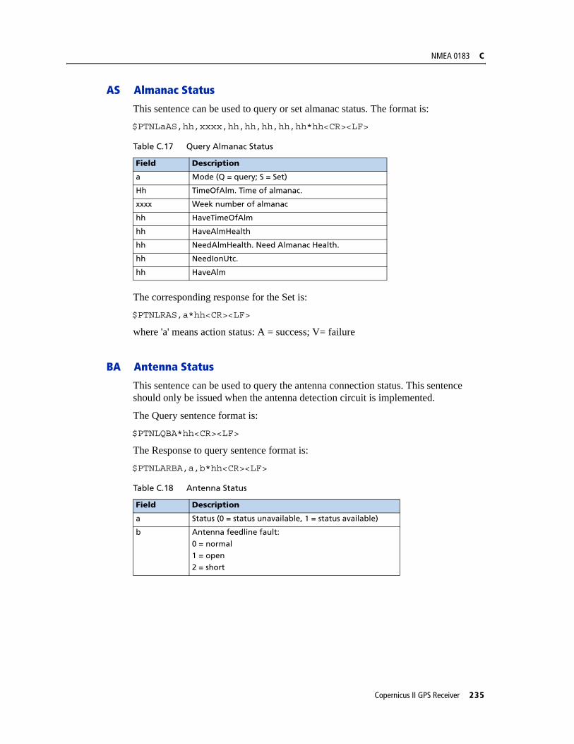
NMEA 0183 C
AS Almanac Status
This sentence can be used to query or set almanac status. The format is:
$PTNLaAS,hh,xxxx,hh,hh,hh,hh,hh*hh<CR><LF>
The corresponding response for the Set is:
$PTNLRAS,a*hh<CR><LF>
where 'a' means action status: A = success; V= failure
BA Antenna Status
This sentence can be used to query the antenna connection status. This sentence should only be issued when the antenna detection circuit is implemented.
The Query sentence format is:
$PTNLQBA*hh<CR><LF>
The Response to query sentence format is:
$PTNLARBA,a,b*hh<CR><LF>
Table C.17 Query Almanac Status
Field Description
a Mode (Q = query; S = Set)
Hh TimeOfAlm. Time of almanac.
xxxx Week number of almanac
hh HaveTimeOfAlm
hh HaveAlmHealth
hh NeedAlmHealth. Need Almanac Health.
hh NeedIonUtc.
hh HaveAlm
Table C.18 Antenna Status
Field Description
a Status (0 = status unavailable, 1 = status available)
b Antenna feedline fault:
0 = normal1 = open2 = short
Copernicus II GPS Receiver 235

C NMEA 0183
CR Configure Receiver
This sentence can query or set NMEA receiver configuration information.
$PTNLaCR,x.x,x.x,x.x,x.x,x.x,a,a,a,a*hh<CR><LF>
EM Enter Monitor Mode
This sentence is used to set the Copernicus II GPS receiver into Monitor Mode. This is Set only, no query supported.
The sentence format is:
$PTNLSEM*hh<CR><LF>
This sentence will be used by the Firmware Uploading Program.
Table C.19 Configure Receiver
Field Description
a Mode (Q = query; S = set; R = Response)
x.x Reserved
x.x Elevation mask in degrees (default = 5 degrees)
x.x Reserved
x.x Reserved
x.x Reserved
a Constellation Mode, default is 0 0 - AUTO
a Dynamics, default is 11=land2=sea3=air4=Stationary/Over-determined
a Reserved.
a 0=WAAS_OFF, 1=WAAS_AUTO (this applies to all SBAS)
236 Copernicus II GPS Receiver
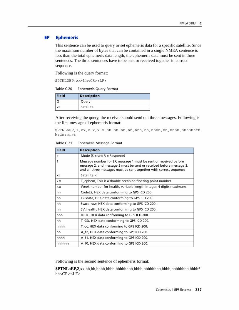
NMEA 0183 C
EP Ephemeris
This sentence can be used to query or set ephemeris data for a specific satellite. Since the maximum number of bytes that can be contained in a single NMEA sentence is less than the total ephemeris data length, the ephemeris data must be sent in three sentences. The three sentences have to be sent or received together in correct sequence.
Following is the query format:
$PTNLQEP,xx*hh<CR><LF>
After receiving the query, the receiver should send out three messages. Following is the first message of ephemeris format:
$PTNLaEP,1,xx,x.x,x.x,hh,hh,hh,hh,hhh,hh,hhhh,hh,hhhh,hhhhhh*hh<CR><LF>
Following is the second sentence of ephemeris format:
$PTNLaEP,2,xx,hh,hh,hhhh,hhhh,hhhhhhhh,hhhh,hhhhhhhh,hhhh,hhhhhhhh,hhhh*hh<CR><LF>
Table C.20 Ephemeris Query Format
Field Description
Q Query
xx Satellite
Table C.21 Ephemeris Message Format
Field Description
a Mode (S = set; R = Response)
1 Message number for EP, message 1 must be sent or received before message 2, and message 2 must be sent or received before message 3, and all three messages must be sent together with correct sequence
xx Satellite id
x.x T_ephem, This is a double precision floating point number.
x.x Week number for health, variable length integer, 4 digits maximum.
hh CodeL2, HEX data conforming to GPS ICD 200.
hh L2Pdata, HEX data conforming to GPS ICD 200.
hh Svacc_raw, HEX data conforming to GPS ICD 200.
hh SV_health, HEX data conforming to GPS ICD 200.
hhh IODC, HEX data conforming to GPS ICD 200.
hh T_GD, HEX data conforming to GPS ICD 200.
hhhh T_oc, HEX data conforming to GPS ICD 200.
hh A_f2, HEX data conforming to GPS ICD 200.
hhhh A_f1, HEX data conforming to GPS ICD 200.
hhhhhh A_f0, HEX data conforming to GPS ICD 200.
Copernicus II GPS Receiver 237

C NMEA 0183
Table C.22 Ephemeris Message Format
Following is the third sentence of ephemeris format
$PTNLaEP,3,xx,hhhh,hhhhhhhh,hhhh,hhhhhhhh,hhhh,hhhhhhhh,hhhhhh,hhhh*hh<CR><LF>
Table C.23 Ephemeris Message Format
Field Description
a Mode (S = set; R = Response)
2 Sentence number for EP, sentence 1 must be sent or received before sentence 2, and sentence 2 must be sent or received before sentence 3, and all three sentences must be sent together
xx Satellite id
hh IODE, Hex data conforming to GPS ICD 200
hh Fit_interval, Hex data conforming to GPS ICD 200
hhhh C_rs, Hex data conforming to GPS ICD 200
hhhh Delta_n, Hex data conforming to GPS ICD 200
hhhhhhhh M_0, Hex data conforming to GPS ICD 200
hhhh C_uc, Hex data conforming to GPS ICD 200
hhhhhhhh E, Hex data conforming to GPS ICD 200
hhhh C_us, Hex data conforming to GPS ICD 200
Field Description
a Mode (S = set; R = Response)
3 Sentence number for EP, sentence 1 must be sent or received before sentence 2, and sentence 2 must be sent or received before sentence 3, and all three sentences must be sent together
xx Satellite id
hh C_ic, Hex data conforming to GPS ICD 200
hh OMEGA_0, Hex data conforming to GPS ICD 200
hhhh C_ri, Hex data conforming to GPS ICD 200
hhhh I_O, Hex data conforming to GPS ICD 200
hhhhhhhh C_rc, Hex data conforming to GPS ICD 200
hhhh OMEGA, Hex data conforming to GPS ICD 200
hhhhhhhh OMEGA_DOT, Hex data conforming to GPS ICD 200
hhhh IDOT, Hex data conforming to GPS ICD 200
238 Copernicus II GPS Receiver
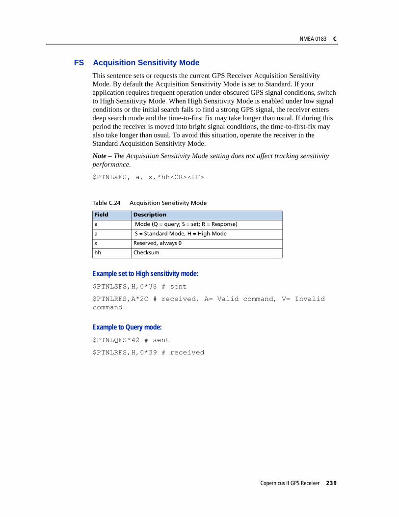
NMEA 0183 C
FS Acquisition Sensitivity ModeThis sentence sets or requests the current GPS Receiver Acquisition Sensitivity Mode. By default the Acquisition Sensitivity Mode is set to Standard. If your application requires frequent operation under obscured GPS signal conditions, switch to High Sensitivity Mode. When High Sensitivity Mode is enabled under low signal conditions or the initial search fails to find a strong GPS signal, the receiver enters deep search mode and the time-to-first fix may take longer than usual. If during this period the receiver is moved into bright signal conditions, the time-to-first-fix may also take longer than usual. To avoid this situation, operate the receiver in the Standard Acquisition Sensitivity Mode.
Note – The Acquisition Sensitivity Mode setting does not affect tracking sensitivity performance.
$PTNLaFS, a, x,*hh<CR><LF>
Example set to High sensitivity mode: $PTNLSFS,H,0*38 # sent
$PTNLRFS,A*2C # received, A= Valid command, V= Invalid command
Example to Query mode: $PTNLQFS*42 # sent
$PTNLRFS,H,0*39 # received
Table C.24 Acquisition Sensitivity Mode
Field Description
a Mode (Q = query; S = set; R = Response)
a S = Standard Mode, H = High Mode
x Reserved, always 0
hh Checksum
Copernicus II GPS Receiver 239

C NMEA 0183
IO Ionosphere
This sentence can be used to query or set ionosphere data.
$PTNLaIO,hh,hh,hh,hh,hh,hh,hh,hh*hh,<CR><LF>
KG Set Initial Position
This sentence can be used to set initial position or time info data or both for accelerating navigation startup. To set time only, send valid time fields and NULL position fields. To set position only, send valid position fields and NULL time fields. Query is not supported.
$PTNLaKG,x.x,x.x,llll.lllll,a,yyyyy.yyyyy,a,x.x*hh<CR><LF>
Note – When uploading a position, it should be within 100 Km of the actual position and time within 5 minutes of UTC.
Table C.25 Ionosphere
Field Description
a Mode (Q = query; S = set; R = Response)
hh Alpha_0, HEX data conforming to GPS ICD 200.
hh Alpha_1, HEX data conforming to GPS ICD 200.
hh Alpha_2, HEX data conforming to GPS ICD 200.
hh Alpha_3, HEX data conforming to GPS ICD 200.
hh Beta_0, HEX data conforming to GPS ICD 200.
hh Beta_1, HEX data conforming to GPS ICD 200.
hh Beta_2, HEX data conforming to GPS ICD 200.
hh Beta_3, HEX data conforming to GPS ICD 200.
Table C.26 Set Initial Position
Field Description
a Mode (S = set; R = Response)
x.x GPS week number, maximum 4 digits
x.x GPS time of week in milliseconds
llll.lllll Latitude
a N | S
yyyyy.yyyyy Longitude
a E | W
x.x Altitude from the sea level in meters (maximum 5 digits)
240 Copernicus II GPS Receiver
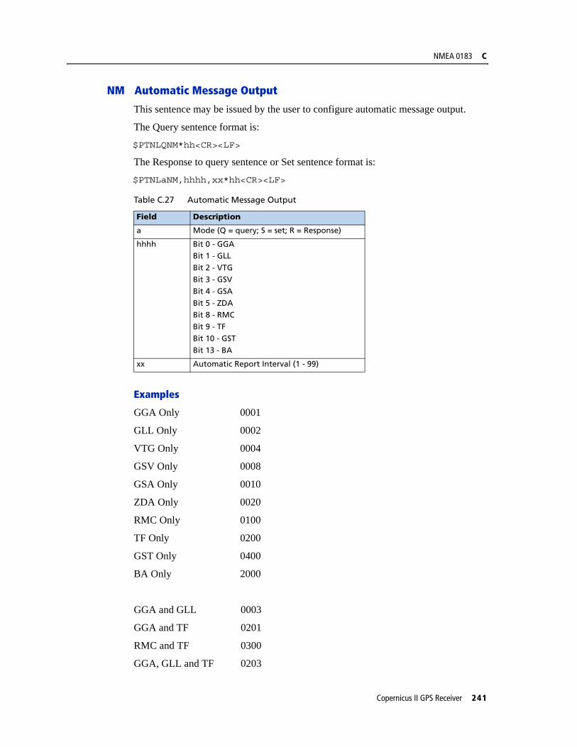
NMEA 0183 C
NM Automatic Message Output
This sentence may be issued by the user to configure automatic message output.
The Query sentence format is:
$PTNLQNM*hh<CR><LF>
The Response to query sentence or Set sentence format is:
$PTNLaNM,hhhh,xx*hh<CR><LF>
Examples
GGA Only 0001
GLL Only 0002
VTG Only 0004
GSV Only 0008
GSA Only 0010
ZDA Only 0020
RMC Only 0100
TF Only 0200
GST Only 0400
BA Only 2000
GGA and GLL 0003
GGA and TF 0201
RMC and TF 0300
GGA, GLL and TF 0203
Table C.27 Automatic Message Output
Field Description
a Mode (Q = query; S = set; R = Response)
hhhh Bit 0 - GGABit 1 - GLL
Bit 2 - VTGBit 3 - GSVBit 4 - GSA
Bit 5 - ZDABit 8 - RMC
Bit 9 - TFBit 10 - GSTBit 13 - BA
xx Automatic Report Interval (1 - 99)
Copernicus II GPS Receiver 241

C NMEA 0183
PS PPS Configuration
This sentence can query or set PPS configuration data.
$PTNLaPS,b,x...x,c,x...x*hh<CR><LF>
PT Serial Port Configuration
This sentence may be issued by the user for configuring the current serial port.
The Query sentence format is:
$PTNLQPT*hh<CR><LF>
The Response to query or Set sentence format is:
$PTNLRPT,xxxxxx,x,a,x,h,h*hh<CR><LF>
When the Set is issued, the first Response sentence will be sent using the old parameters and the second response sentence will be sent using the new parameters. If there is an error, there will be an error response sent. If there is no error, no additional response is sent.
Table C.28 PPS Configuration
Field Description
a Mode (Q = query; S = set; R = Response)
b PPS mode, default is 1:0 - PPS_OFF (Always Off)1 - PPS_ON (Always On or Early PPS)
2 - PPS_FIX_BASED3 - reserved
x...x Output pulse length in 100 nanoseconds, default is 42 corresponding to 4200 nanoseconds. Pulse length range is 100ns to 500ms. Field value range is 1 to 5000000.
c Output pulse polarity, default is 1:
0 - output pulse is active low1 - output pulse is active high
x...x Antenna Cable Length Compensation. Default = 0, Units in nanoseconds. Can be positive or negative. Negative value will mean PPS comes out earlier, e.g. to compensate for cable delay.
Table C.29 Serial Port Configuration
Field Description
a Mode (Q = query; R = Response; S = Set)
xxxxxx Baud rate (4800, 9600, 19200, 38400, 57600, 115200). Default baud rate is 4800
x Data bits, use only 8
a Parity, use only N
x Stop bits, use only 1
242 Copernicus II GPS Receiver

NMEA 0183 C
Example
$PTNLSPT,004800,8,N,1,4,4*11
Sets the port to:
– baud = 4800
– data bits = 8
– parity = none
– stop bits = 1
– input = NMEA
– output = NMEA
h Input protocol, hex value (bit 0: TAIP, bit1: TSIP, bit2: NMEA)
Bits can be combined to enable multiple input protocolsThis field may not be 0
h Output protocol, hex value (bit 0: TAIP, bit1: TSIP, bit2: NMEA)It is not recommended to combine multiple output protocols
Table C.29 Serial Port Configuration
Field Description
Copernicus II GPS Receiver 243
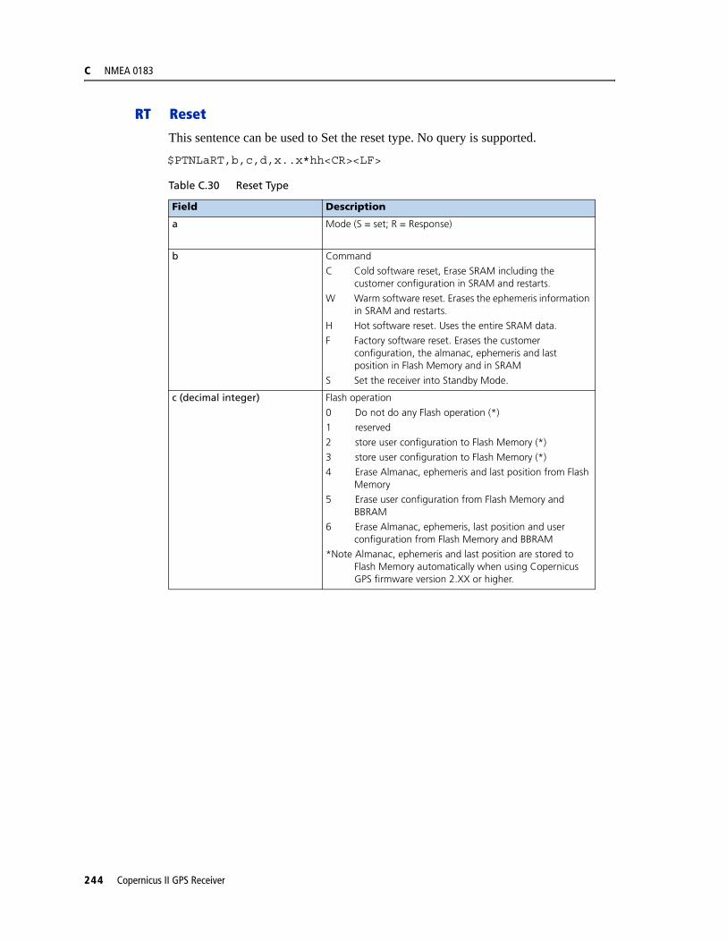
C NMEA 0183
RT Reset
This sentence can be used to Set the reset type. No query is supported.
$PTNLaRT,b,c,d,x..x*hh<CR><LF>
Table C.30 Reset Type
Field Description
a Mode (S = set; R = Response)
b Command
C Cold software reset, Erase SRAM including the customer configuration in SRAM and restarts.
W Warm software reset. Erases the ephemeris information in SRAM and restarts.
H Hot software reset. Uses the entire SRAM data.
F Factory software reset. Erases the customer configuration, the almanac, ephemeris and last position in Flash Memory and in SRAM
S Set the receiver into Standby Mode.
c (decimal integer) Flash operation
0 Do not do any Flash operation (*)
1 reserved
2 store user configuration to Flash Memory (*)
3 store user configuration to Flash Memory (*)
4 Erase Almanac, ephemeris and last position from Flash Memory
5 Erase user configuration from Flash Memory and BBRAM
6 Erase Almanac, ephemeris, last position and user configuration from Flash Memory and BBRAM
*Note Almanac, ephemeris and last position are stored to Flash Memory automatically when using Copernicus GPS firmware version 2.XX or higher.
244 Copernicus II GPS Receiver
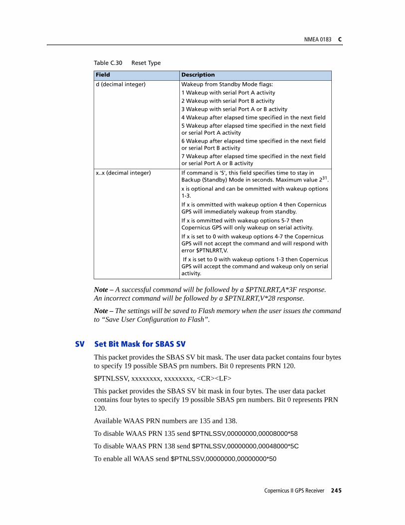
NMEA 0183 C
Note – A successful command will be followed by a $PTNLRRT,A*3F response. An incorrect command will be followed by a $PTNLRRT,V*28 response.
Note – The settings will be saved to Flash memory when the user issues the command to “Save User Configuration to Flash”.
SV Set Bit Mask for SBAS SV
This packet provides the SBAS SV bit mask. The user data packet contains four bytes to specify 19 possible SBAS prn numbers. Bit 0 represents PRN 120.
$PTNLSSV, xxxxxxxx, xxxxxxxx, <CR><LF>
This packet provides the SBAS SV bit mask in four bytes. The user data packet contains four bytes to specify 19 possible SBAS prn numbers. Bit 0 represents PRN 120.
Available WAAS PRN numbers are 135 and 138.
To disable WAAS PRN 135 send $PTNLSSV,00000000,00008000*58
To disable WAAS PRN 138 send $PTNLSSV,00000000,00048000*5C
To enable all WAAS send $PTNLSSV,00000000,00000000*50
d (decimal integer) Wakeup from Standby Mode flags:
1 Wakeup with serial Port A activity2 Wakeup with serial Port B activity3 Wakeup with serial Port A or B activity
4 Wakeup after elapsed time specified in the next field5 Wakeup after elapsed time specified in the next field or serial Port A activity6 Wakeup after elapsed time specified in the next field or serial Port B activity
7 Wakeup after elapsed time specified in the next field or serial Port A or B activity
x..x (decimal integer) If command is 'S', this field specifies time to stay in Backup (Standby) Mode in seconds. Maximum value 231.
x is optional and can be ommitted with wakeup options 1-3.
If x is ommitted with wakeup option 4 then Copernicus GPS will immediately wakeup from standby.
If x is ommitted with wakeup options 5-7 then Copernicus GPS will only wakeup on serial activity.
If x is set to 0 with wakeup options 4-7 the Copernicus GPS will not accept the command and will respond with error $PTNLRRT,V.
If x is set to 0 with wakeup options 1-3 then Copernicus GPS will accept the command and wakeup only on serial activity.
Table C.30 Reset Type
Field Description
Copernicus II GPS Receiver 245
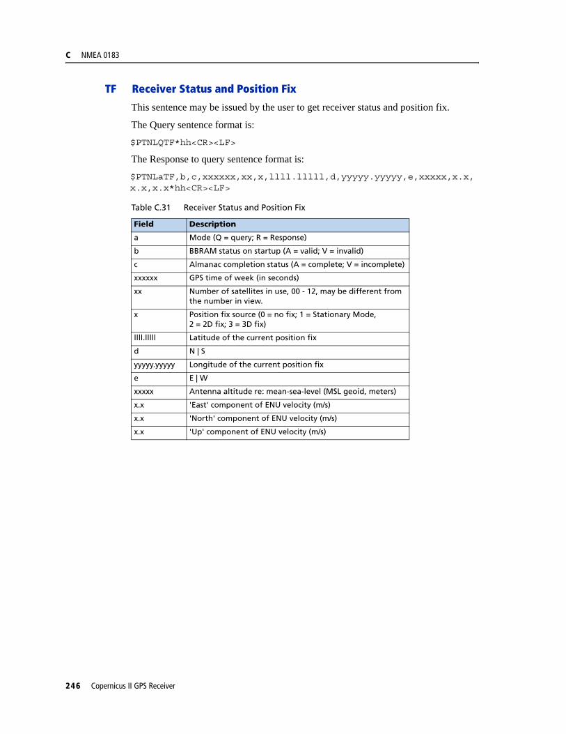
C NMEA 0183
TF Receiver Status and Position Fix
This sentence may be issued by the user to get receiver status and position fix.
The Query sentence format is:
$PTNLQTF*hh<CR><LF>
The Response to query sentence format is:
$PTNLaTF,b,c,xxxxxx,xx,x,llll.lllll,d,yyyyy.yyyyy,e,xxxxx,x.x,x.x,x.x*hh<CR><LF>
Table C.31 Receiver Status and Position Fix
Field Description
a Mode (Q = query; R = Response)
b BBRAM status on startup (A = valid; V = invalid)
c Almanac completion status (A = complete; V = incomplete)
xxxxxx GPS time of week (in seconds)
xx Number of satellites in use, 00 - 12, may be different from the number in view.
x Position fix source (0 = no fix; 1 = Stationary Mode,2 = 2D fix; 3 = 3D fix)
llll.lllll Latitude of the current position fix
d N | S
yyyyy.yyyyy Longitude of the current position fix
e E | W
xxxxx Antenna altitude re: mean-sea-level (MSL geoid, meters)
x.x 'East' component of ENU velocity (m/s)
x.x 'North' component of ENU velocity (m/s)
x.x 'Up' component of ENU velocity (m/s)
246 Copernicus II GPS Receiver
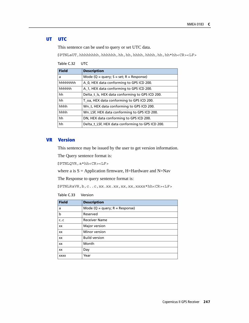
NMEA 0183 C
UT UTC
This sentence can be used to query or set UTC data.
$PTNLaUT,hhhhhhhh,hhhhhh,hh,hh,hhhh,hhhh,hh,hh*hh<CR><LF>
VR Version
This sentence may be issued by the user to get version information.
The Query sentence format is:
$PTNLQVR,a*hh<CR><LF>
where a is S = Application firmware, H=Hardware and N=Nav
The Response to query sentence format is:
$PTNLRaVR,b,c..c,xx.xx.xx,xx,xx,xxxx*hh<CR><LF>
Table C.32 UTC
Field Description
a Mode (Q = query; S = set; R = Response)
hhhhhhhh A_0, HEX data conforming to GPS ICD 200.
hhhhhh A_1, HEX data conforming to GPS ICD 200.
hh Delta_t_ls, HEX data conforming to GPS ICD 200.
hh T_oa, HEX data conforming to GPS ICD 200.
hhhh Wn_t, HEX data conforming to GPS ICD 200.
hhhh Wn_LSF, HEX data conforming to GPS ICD 200.
hh DN, HEX data conforming to GPS ICD 200.
hh Delta_t_LSF, HEX data conforming to GPS ICD 200.
Table C.33 Version
Field Description
a Mode (Q = query; R = Response)
b Reserved
c..c Receiver Name
xx Major version
xx Minor version
xx Build version
xx Month
xx Day
xxxx Year
Copernicus II GPS Receiver 247

C NMEA 0183
248 Copernicus II GPS Receiver