for more information visit rand at explore ... · this pdf document was made available from as a...
TRANSCRIPT

This PDF document was made available
from www.rand.org as a public service of
the RAND Corporation.
6Jump down to document
Purchase this document
Browse Books & Publications
Make a charitable contribution
Visit RAND at www.rand.org
Explore the RAND Arroyo Center
View document details
This document and trademark(s) contained herein are protected by law as indicated in a notice appearing later in this work. This electronic representation of RAND intellectual property is provided for non-commercial use only. Permission is required from RAND to reproduce, or reuse in another form, any of our research documents.
Limited Electronic Distribution Rights
For More Information
Support RAND
CHILDREN AND ADOLESCENTS
CIVIL JUSTICE
EDUCATION
ENERGY AND ENVIRONMENT
HEALTH AND HEALTH CARE
INTERNATIONAL AFFAIRS
POPULATION AND AGING
PUBLIC SAFETY
SCIENCE AND TECHNOLOGY
SUBSTANCE ABUSE
TERRORISM AND HOMELAND SECURITY
TRANSPORTATION ANDINFRASTRUCTURE
U.S. NATIONAL SECURITY
The RAND Corporation is a nonprofit research organization providing objective analysis and effective solutions that address the challenges facing the public and private sectors around the world.

This product is part of the RAND Corporation monograph series.
RAND monographs present major research findings that address the
challenges facing the public and private sectors. All RAND mono-
graphs undergo rigorous peer review to ensure high standards for
research quality and objectivity.

LELAND JOE
ISAAC PORCHE III
Prepared for the United States ArmyApproved for public release, distribution unlimited
Future ArmyBandwidth Needsand Capabilities

The RAND Corporation is a nonprofit research organization providingobjective analysis and effective solutions that address the challengesfacing the public and private sectors around the world. RAND’spublications do not necessarily reflect the opinions of its research clientsand sponsors.
R® is a registered trademark.
© Copyright 2004 RAND Corporation
All rights reserved. No part of this book may be reproduced in any formby any electronic or mechanical means (including photocopying,recording, or information storage and retrieval) without permission inwriting from RAND.
Published 2004 by the RAND Corporation1700 Main Street, P.O. Box 2138, Santa Monica, CA 90407-2138
1200 South Hayes Street, Arlington, VA 22202-5050201 North Craig Street, Suite 202, Pittsburgh, PA 15213-1516
RAND URL: http://www.rand.org/To order RAND documents or to obtain additional information, contact
Distribution Services: Telephone: (310) 451-7002; Fax: (310) 451-6915; Email: [email protected]
The research described in this report was sponsored by the United StatesArmy under Contract No. DASW01-01-C-0003.
Library of Congress Cataloging-in-Publication Data
Joe, Leland.Future army bandwidth needs and capabilities / Leland Joe, Issac Porche III.
p. cm.Includes bibliographical references.“MG-156.”ISBN 0-8330-3545-2 (pbk.)1. United States. Army–Communication systems. 2. Broadband communication
systems—United States. I. Porche, Isaac, 1968– II.Title.
UG593.J64 2004355.2'7—dc22
2004009651
iii
Preface
This report presents the results for a RAND Arroyo Center project,“Future Army Bandwidth Needs.” The research documented hereaddresses the problems of designing the Army’s future communica-tions network to meet competing demands at a time of rapidlychanging user needs and technologies. The research will interest thecombat development, research and development, and acquisitioncommunities.
This project was sponsored by the G-6 and CIO, HeadquartersDepartment of the Army, and was conducted within RAND ArroyoCenter’s Force Development and Technology Program. RAND Ar-royo Center, part of the RAND Corporation, is a federally fundedresearch and development center sponsored by the United StatesArmy.

iv Future Army Bandwidth Needs and Capabilities
For more information on RAND Arroyo Center, contact theDirector of Operations (telephone 310-393-0411, extension 6419;FAX 310-451-6952; e-mail [email protected]), or visit Ar-royo’s web site at http://www.rand.org/ard/.

v
The RAND Corporation Quality Assurance Process
Peer review is an integral part of all RAND research projects. Prior topublication, this document, as with all documents in the RANDmonograph series, was subject to a quality assurance process to ensurethat the research meets several standards, including the following:The problem is well formulated; the research approach is well de-signed and well executed; the data and assumptions are sound; thefindings are useful and advance knowledge; the implications and rec-ommendations follow logically from the findings and are explainedthoroughly; the documentation is accurate, understandable, cogent,and temperate in tone; the research demonstrates understanding ofrelated previous studies; and the research is relevant, objective, inde-pendent, and balanced. Peer review is conducted by research profes-sionals who were not members of the project team.
RAND routinely reviews and refines its quality assurance pro-cess and also conducts periodic external and internal reviews of thequality of its body of work. For additional details regarding theRAND quality assurance process, visit http://www.rand.org/standards/.


vii
Contents
Preface ................................................................. iiiFigures ................................................................. xiTables ................................................................. xiiiSummary ...............................................................xvAcknowledgments ..................................................... xxiGlossary ..............................................................xxiii
CHAPTER ONE
Introduction ............................................................1Background .............................................................1
Link Capacity.........................................................2Network Capacity.....................................................3Factors Affecting Network Capacity....................................4Performance Measures.................................................7Enhancing Network Capacity..........................................8
Problem .................................................................9Methodology .......................................................... 11How This Report Is Organized ......................................... 12
CHAPTER TWO
Current and Near-Term Capabilities.................................. 15Needs Based On Information Exchange Requirements................... 15Needs Based On Experimental Measurements ........................... 17Supporting Needs: Current and Near-Term Systems .................... 19Summary and Conclusions ............................................. 22

viii Future Army Bandwidth Needs and Capabilities
CHAPTER THREE
Future Communication Needs and System Capabilities............... 25Future Combat Systems Concept ....................................... 25Future Needs .......................................................... 27Challenges and Opportunities .......................................... 29Overall Terrestrial Network ............................................ 29
Terrestrial Network Challenges ...................................... 30Terrestrial Opportunities: Factors Affecting Capacity in Ad Hoc
Networks ........................................................ 31Soldier Network ....................................................... 33
Soldier Network Challenges ......................................... 34Soldier Network Opportunities: New Programs and Systems .......... 34
Airborne Networks..................................................... 35Airborne Network Layer Challenges.................................. 35Airborne Network Opportunities: Adding a Vertical Node ............ 36
Space Networks........................................................ 37Space Network Challenges: Limitations of Optical Links.............. 37Space Network Opportunities: New Technologies and Systems ....... 39
Network Architecture: Interconnections Among the Layers .............. 41Summary and Conclusions ............................................. 42
CHAPTER FOUR
Ways to Increase Capacity ............................................ 43Increasing Capacities of Links .......................................... 43Utilizing Directional Antennas ......................................... 46
Advantages and Disadvantages of Directional Antennas ............... 47Simulation Results Using Directional Antennas....................... 48
Improving Routing Efficiency .......................................... 49Adding a Vertical Element ............................................. 49Adjusting Needs of Applications ........................................ 51Managing Bandwidth .................................................. 52Assessing and Comparing Improvement Techniques..................... 53Summary and Conclusions ............................................. 55

Contents ix
CHAPTER FIVE
Major Findings and Recommendations ............................... 57Major Findings ........................................................ 57Specific Recommendations ............................................. 58
Reassess Information Demands and Needs ........................... 58Change Application Structure ....................................... 59Manage Operational Demands to Meet Needs........................ 59Increase Efficiency of Network Routing .............................. 59Increase Capacities of Links.......................................... 59
Overall Assessment and Recommendations.............................. 61
APPENDIX
A. Commercial Communication Technological Advances .............. 63B. Routing Protocols for MANETs.................................... 83C. Who’s Working the Problem and Emerging Concepts ............... 89
References ............................................................. 97

xi
Figures
1.1. Information Grid Connects the Various Distributed Sensorsand Shooters Across the Battlespace ..............................2
1.2. A Simple Network...............................................41.3. Throughput as a Function of “Hops” Using Commercial
Standards/Protocols..............................................51.4. Capacity of a (Random Access) Network Decreases with Size ......71.5. The NTDR Hierarchical Scheme Intends to Utilize
“Backbone” Nodes to Reduce Average Path Length ...............91.6. Bandwidth Demand Continues to Grow........................ 101.7. Initial Estimates Suggest Future Requirements (Demand) Will
Exceed Existing Supply ........................................ 122.1. Brigade Communications Usage During Division Advanced
Warfighting Experiment ....................................... 172.2. Variations in Operational Bandwidth Demands in DAWE
(Minus Data from Intel and Log Units) ........................ 182.3. Spectral Efficiency of Various Radios ........................... 223.1. Layers of the Infosphere........................................ 263.2. FCS Unit of Action............................................ 273.3. Unit of Action Bandwidth Requirements: Breakdown by
Demand ...................................................... 283.4. Peak Requirements (Mbps) by Unit for the Unit of Action ...... 283.5. Capacity Challenges for DoD as of June 2002 .................. 373.6. Proposed TCA Increases Cross-link Capacity Using Optical and
RF Links ...................................................... 404.1. Military Can Use Higher Frequencies .......................... 45

xii Future Army Bandwidth Needs and Capabilities
4.2. Fixed Spectrum Assignments Lead to Inefficient Utilization ..... 454.3. UAVs Add Connectivity and Capacity But Could Require
Large Numbers of Vehicles..................................... 514.4. Compression Reduces Bandwidth Demands, Increases
Computing Demands.......................................... 52A.1. Today’s Commercial Industry Relies Heavily on Fixed
Infrastructure.................................................. 65A.2. OFDM Process................................................ 72A.3. OFDM Efficiency via Subcarrier Overlap ....................... 73A.4. Steered Beam Antennas ........................................ 81C.1. MOSAIC Envisions UAV/SATCOM Utilization for Mobile
Nodes......................................................... 94

xiii
Tables
2.1. Characterization of SBCT Information Flow fromCACACOA 3.1 Data .......................................... 16
2.2. SBCT Information System Architecture ........................ 202.3. Assessment of Current and Near-Term System Capabilities...... 213.1. Protocols for Wireless Area Networks Are Being Developed
(Commercially) with High Potential Throughputs But RealizeFar Less ....................................................... 33
3.2. Optical Link Performance Is Attenuated in the Atmosphere ..... 384.1. Techniques to Increase Bandwidth ............................. 444.2. Relative Capacity Gains from Using Directional Antennas....... 474.3. Throughput Improvements for Two Networks Using
Directional Antennas .......................................... 494.4. Relative Value of Bandwidth Techniques Depends on
Operational Situation (Network Topology) ..................... 544.5. Bandwidth Improvements Trade Off with Other Performance
Factors ........................................................ 55A.1. Army’s Networking Needs Do Not Align with Today’s
Industry Focus ................................................ 64A.2. OFDM and OFDM-Inspired Types............................ 74A.3. Comparisons of Selected Wireless Communication
Technologies .................................................. 79B.1. Routing Protocols in Development and/or Proposed ............ 87C.1. DARPA FCS Communications Program Funded Initiatives ..... 91


xv
Summary
Across the services, there is an increasing demand for communica-tions capacity. For the U.S. Army, this is a result of the Army’s tran-sition to a new force structure that will be knowledge-based1 andnetwork-centric.2 Since bandwidth facilitates communications capac-ity, bandwidth has become increasingly critical. To the user, highbandwidth is useful because it supports increased capacity, high-volume data exchange, short delays, and high assurance of connec-tivity. New technologies, commercial and military, will continue toincrease available bandwidth and hence the communications capacityavailable to users. Based on specified requirements and proposedtechnologies and architectures for the future force, the capacity ofcommunications systems planned to support the new force structurewill continue to fall short of the required demand.
With unlimited spectrum and unlimited budget, the Armycould resolve its bandwidth issues. But these are unrealistic assump-tions. Certainly, demand reduction can help close the gap betweenthe requirements and availability of network capacity. However, it isnot clear how much demand reduction is possible while retaining theinformation dominance that is critical for the future force. Demandreduction will need to be coupled with technology investments (e.g.,satellites, UAVs, directional antennas, more radios). A number of
____________1 Casper et al. (1996).2 Cebrowski and Garstka (1998).

xvi Future Army Bandwidth Needs and Capabilities
technologies and concepts are being developed to enhance spectralefficiency, thus allowing the Army to make the best use of the avail-able spectrum. Gaps between the supply and demand of capacity,both now and in the future, will have to be addressed by constantlyreassessing demand for capacity and developing technologies that in-crease the supply.
It is important to note that bandwidth is not the only issue withregard to networked communication. Among the other critical issuesare communications-on-the-move (not widely possible in OperationIraqi Freedom) and interoperability. The Joint Tactical Radio Systemwill be required to address these two issues.
Although the Army can take advantage of commercially devel-oped technologies, the Army’s operational situation differs funda-mentally from that of industry. Currently, the Army differs fromcommercial industry in its approach to user and communications in-frastructure mobility, information assurance (i.e., secure communica-tion), and interoperability. It is not clear that the commercial worldwill be the source of all of the technology solutions. Department ofDefense (DoD) funded initiatives are likely to be critical to the devel-opment of the key technologies.
Recent RAND Arroyo Center research analyzed how the Armyuses bandwidth. As a result, this report describes a number of specificsteps that can be taken to address the gap. They are listed below inorder of priority, where priority is assigned to the steps that are likelyto lead to the largest gains, based on our assessment.
Reassess Information Demands and Needs
The Army must perform experiments to understand what drives“real-world” information demands. There exists only a scant amountof data on the details of real-world demands and there has been littleanalysis of the necessity and the value of proposed information flowsat each of the various echelons. Furthermore, the Army must reassessthe necessity of these information requests. More experimentation is

Summary xvii
needed to test how various information demands contribute to mis-sion success.
Change Application Structure
Applications determine the volume and timing of a large part of in-formation flow. Adjusting applications demands, such as by compres-sion, can decrease bandwidth requirements by orders of magnitude.Minimizing the need to transmit raw sensor data will be beneficial,especially if local fusion is feasible. However, explicit performanceassessments must be conducted to maintain quality with respect todata fusion and compression.
Manage Operational Demands to Meet Needs
Information traffic patterns exhibit differing needs for different pri-ority users. Changing information needs require a dynamic networkmanagement approach to prioritize and smooth flow through thenetwork. This has already been explicitly recommended in an Opera-tion Iraqi Freedom after action report.3
Increase Efficiency of Network Routing
Army communications are increasingly network based and must beaddressed from a network perspective. The Army Communications-Electronics Command (CECOM), the Defense Advanced ResearchProjects Agency (DARPA), and commercial industry are attemptingto increase capacity through more efficient routing through networks.
____________3 Shaaber, Hedberg, and Wesson (2003) call for the “ability to manage bandwidth usagedynamically at the discretion of the commander [to allocate bandwidth] commensurate withoperational priorities.”

xviii Future Army Bandwidth Needs and Capabilities
These techniques take advantage of knowledge of the network state toimprove routing efficiency.
Increase Capacities of Links
Both CECOM and DARPA (e.g., in their FCS Communications andNext-Generation Communications programs) are working to increaselink capacities by using higher frequencies and directional antennas.Theoretical assessments by Yi, Pei, and Kalyanaraman (2003) showthat the capacity-multiplying effect of directional antennas over to-day’s nondirectional (omnidirectional) antennas could be as high asone to two orders of magnitude, depending on the technology used.These are better results than what has been seen in simulation ofvarious types of directional systems. Clearly, the opportunity for im-provement exists, and more development is needed to fully realize thebenefits of this concept. If directional antenna systems can be devel-oped to their full potential, they could help ameliorate the inherentcapacity limitations of large numbers of radios sharing a frequencychannel.
Today’s fixed, limited frequency allocation of available spectrumcreates a hard limit on the amount of capacity, especially for groundvehicles on the move. Commercial demands in the United States,Europe, and elsewhere are squeezing the available spectrum for use bythe U.S. military and its allies.4 By one estimate, there may be as littleas 55 MHz available5 today for the Army; this could translate into 50to 100 Mbps capacity for a given area of operation, at best. (Such
____________4 Quoting: “high-tech companies are lobbying to block the recent DOD proposal [to openup the 5,150 to 5,720] megahertz band to accommodate the burgeoning industry.” Inside thePentagon, “DoD Battles Industry on Spectrum Wanted for Wireless Networking,” December2002.5 This is when given only the JTRS threshold operating frequencies, which are between 2Mhz and 2 Ghz, when considering availability for the Future Combat Systems (FCS) com-munication network. U.S. Army, “FCS WNW Spectrum Requirement” white paper, De-cember 6, 2002.

Summary xix
limited spectrum access in CONUS also prohibits the “train as youfight” notion.) The lower end of this range may not be sufficient toaccommodate one brigade-sized unit’s situational awareness needs.6
Spectral reuse is key to achieving as much capacity as possible.Directional antennas facilitate reuse even with fixed fre-quency/spectral allocations. Fully dynamic spectrum managementcould facilitate even greater reuse of the spectrum by obviating theneed for static channel/frequency assignments. DARPA is developingtechnologies to enable dynamic access to radio frequency spectrum.This is an important technology concept that needs to continue de-velopment.
Overall Assessment and Recommendations
Bandwidth is a limited resource that needs to be managed. Newtechnologies will greatly increase capacity, but unchecked user de-mands will probably keep pace and exceed available capacities. Nosingle technique will solve the problem. There are no silver bullets.
The challenge is to meet the right users’ needs at the right time.To achieve this, it is recommended the Army do the following. First,bandwidth needs to be treated as an operational resource to be allo-cated by commanders and staffs. Second, the Army should continueto pursue all technologies that could provide benefit. Technology de-velopment should be synchronized through a single cognizant agencyfor efficiency and coordination. This includes not only communica-tions systems but also systems-of-systems to reduce demands and cre-ate an overall information architecture. Third, the Army should de-velop and refine assessment tools; better assessment tools are neededto make complex tradeoffs. Last, the Army needs to make a partner ofDoD to avoid unnecessary redirection and to take advantage of DoD-wide capabilities. This is especially important with respect to the
____________6 Assuming an average situational awareness (SA) data rate of 64 kilobits per second pervehicle/node and a 1,000+ node brigade.

xx Future Army Bandwidth Needs and Capabilities
DoD efforts to maintain and perhaps acquire new spectral alloca-tions.

xxi
Acknowledgments
The authors would like to thank Lewis Saunders, COL Philip Ver-meer, LTG Peter Couviello, and LTG Steven Boutelle of the Officeof the Chief Information officer, G-6, U.S. Army, for their assistancein and support for this research project.
LTC Larry Gordon made contributions to this report. He pro-vided important guidance and direction as well as access to data.
We are indebted to our RAND Corporation colleagues, includ-ing Jerry Sollinger, Ken Horn, and Tom McNaugher, who providedimportant advice and counsel during the course of this study. LouMoore and Ed Balkovich served as the technical reviewers of this re-port.
The RAND support staff is what keeps the work moving; wewould like to especially thank Stephanie Sutton for her many contri-butions. We, of course, remain responsible for the observations andjudgments contained in this report.

xxiii
Glossary
1G First Generation Mobile Phone Technology
2G Second Generation Mobile Phone Technology
3G Third Generation Mobile Phone Technology4G Fourth Generation Mobile Phone Technology
ACT Airspace Control Team
ADPCM Adaptive Differential Pulse Code Modulation
AJ Anti-jamming
AMSAA Army Materiel Systems Analysis Activity
AODV Ad hoc On-Demand Distance VectorAP Access Point
ARL Army Research Laboratory
ARO Army Research Office
ASD (NII) Assistant Secretary of Defense for Networks andInformation Integration (formerly ASD/C3I)
ASD/C3I Assistant Secretary of Defense for Command,Control, Communications, and Intelligence
ATM Asynchronous Transfer Mode
bps Bits per second
C2 Command and ControlC3I Command, Control, Communications, and
Intelligence

xxiv Future Army Bandwidth Needs and Capabilities
C4ISR Command, Control, Communications, Computers,Intelligence, Surveillance, and Reconnaissance
CBRP Cluster Based Routing Protocol
CDMA Code Division Multiple Access
CECOM (U.S. Army) Communications-Electronics Command
CEDAR Core Extraction Distributed Ad Hoc RoutingCERDEC CECOM Research, Development, and Engineering
CenterCOTS Commercial-off-the-Shelf
CSMA/CA Carrier Sense Multiple Access/Collision Avoidance
CTS Clear to Send
DARPA Defense Advanced Research Projects Agency
DAWE Division Advanced Warfighting Experiment
DISN Defense Integrated Systems NetworkDMS Defense Message System
DMTD Digital Message Transfer Device
DoD Department of Defense
DSDV Destination Sequence Distance Vector
DSR Dynamic Source Routing
DSSS Direct Sequence Spread SpectrumEHF Extremely High Frequency
EPLRS Enhanced Position Location Reporting System
FADAC Field Artillery Digital Automatic Computer
FBCB2 Force (XXI) Battle Command Brigade and BelowSystems
FCS Future Combat Systems
FH-CDMA Frequency Hopping Code Division Multiple Access
FHSS Frequency Hopping Spread SpectrumFLIRS Forward Looking Infrared System
FM Frequency Modulation

Glossary xxv
Gbps Gigabits per second
GBS Global Broadcast System
GCCS Global Command and Control System
GHz GigahertzGIG Global Information Grid
GPS Global Positioning System
GSM Global Systems for Mobile Communication
HCLOS High-Capacity Line of Sight
HF High Frequency
Hz HertzIEEE Institute for Electrical and Electronic Engineers
ISM Industrial, Scientific, and Medical
ISO International Standards Organization
ISYSCON Integrated System Control
JTRS Joint Tactical Radio System
LAM Loitering Attack MissileLAN Local Area Network
LOS Line of Sight
LPD Low Probability of Detection
LPI Low Probability of Intercept
LW Land Warrior
MANET Mobile Ad Hoc NetworkMbps Megabits per second
MCM Multicarrier Modulation
MHz Megahertz
MOSAIC Multifunctional On-the-Move Secure Adaptive Inte-grated Communications
MSE Mobile Subscriber Equipment
MSRT Mobile Subscriber Radio Terminal

xxvi Future Army Bandwidth Needs and Capabilities
NETEX Networking in Extreme Environments
NSSA National Security Space Architect
NTDR Near-Term Digital Radio
ODMA Orthogonal Division Multiple AccessOEF Operation Enduring Freedom
OFDM Orthogonal Frequency Division Multiplexing
OIF Operation Iraqi Freedom
OLSR Optimized Link State Routing Protocol
ORD Operational Requirements Document
PAM Precision Attack MissilePBX Private Branch Exchange
PDC Personal Digital Cellular or Personal DigitalCommunication
PN Pseudo Noise
QoS Quality of Service
RDMAR Relative Distance Micro-Discovery Ad hoc Routing
RF Radio Frequency
RTS Request to SendSA Situational Awareness
SBCT Stryker Brigade Combat Team
SHF Super High Frequency
SINCGARS Single-Channel Ground and Airborne Radio System
SMART-T Secure Mobile Anti-Jam Reliable Tactical-Terminal
SS Spread SpectrumSTAR Source Tree Adaptive Routing
SUO SAS Small Unit Operations Situation Awareness System
SUV Sports Utility Vehicle
TCA Transformational Communication Architecture
TCP Transmission Control Protocol or Transfer ControlProtocol

Glossary xxvii
TDMA Time Division Multiple Access
THOR Tera Hertz Operational Reachback
THSDN Tactical High Speed Data Network
TORA Temporally Ordered Routing AlgorithmTRAC Training and Doctrine Command Analysis Center
UAV Unmanned Aerial Vehicle
UDAAN Utilizing Directional Antennas for Ad hocNetworking
UGS Unattended Ground Sensors
UHF Ultra High Frequency
VAA Vehicle Amplifier/Adapter Assembly
VHF Very High FrequencyWLAN Wireless Local Area Network
ZRP Zone Routing Protocol


1
CHAPTER ONE
Introduction
Background
The Army is moving toward network-based communications inwhich all users (sensors, shooters, commanders, etc.) are intercon-nected as part of an information grid (see Figure 1.1). The informa-tion grid is a network of networks supporting voice, video, and datatransmissions. It supports more than just the passing of targeting in-formation through sensor-to-shooter loops; such a grid also provides,for example, real-time collaboration and dynamic planning. From acommunications standpoint, a key measure of a network is its capac-ity to transmit and receive information. In the Army, the term“bandwidth” is synonymous with the capacity of its communicationnetworks.
The Army’s networked approach has both technical and opera-tional advantages. It offers technical advantages in that networkedcommunications effectively extend the range of communications,since any user in a network can connect to any other user through thenetwork. Operationally, sensors, command and control units, andshooters are interconnected to maximize their effectiveness.
Networking, especially that based on Internet protocols, can alsotake advantage of commercially developed software applications forinformation sharing and collaboration. The remainder of this sectiondescribes basic definitions of links, networks, link capacity, networkcapacity, and bandwidth.

2 Future Army Bandwidth Needs and Capabilities
Figure 1.1Information Grid Connects the Various DistributedSensors and Shooters Across the Battlespace
Sensors
C2
ShooterInfo
Control
Control
INFO GRID
Info
Info
RAND MG156-1.1
SOURCE: Cebrowski and Garstka (1998).
Link Capacity
Networks are made up of nodes, which in the context of the militaryare command vehicles, soldiers, sensors, and other users and produc-ers of information. Nodes are said to be connected (or linked) if theycan exchange information. Such links are facilitated using radios, sat-ellite terminals, and other communication devices. The capacity of alink is quantified in terms of the maximum rate of information flowon the network, i.e., the maximum number of bits that can be trans-mitted per second. Link capacity is a function of the bandwidth (i.e.,frequencies spanned) as indicated by Shannon’s equation as follows:
C=W·log2(1 + SNR),

Introduction 3
where
C = capacity, bits/sec,W = bandwidth, Hz,SNR = signal to noise ratio.
This equation assumes (1) an Additive White Gaussian Noise(AWGN) channel and (2) a single-input single-output (SISO) sys-tem.
It is important to note that if a fixed amount of bandwidth isallocated for an application, it has a finite amount of capacity. Inother words, bandwidth and link capacity are inextricably linked(and, thus, so are spectrum allocation and capacity). Note that thetwo terms “bandwidth” and “capacity” are often used interchangeablydespite the fact that they differ depending on the context.
The term spectrum also refers to a range (or band) of frequen-cies measured in Hertz (Hz). Spectral efficiency is a measure that re-lates the data rates possible for a given span of frequencies. It is meas-ured in bits per second per Hertz. Spectral efficiency depends on thecommunication technologies involved and could be lower or greaterthan one. The spectral efficiencies of various Army radios are com-pared in Chapter Two.
In general, higher frequencies and larger frequency bands facili-tate higher capacities. Note that secure communication (e.g., re-quirements of low probability of detection, low probability of inter-cept, and/or anti-jam) can have a lower spectral efficiency.
Network Capacity
The capacity of a network, as a whole, differs from the capacity ofindividual links within that network. The capacity of a network isdetermined by the capacities of the links and is also expressed in bitsper second. Total network capacity for a fixed wired network is oftentabulated as the sum of link capacities between network nodes. As anexample, consider Figure 1.2, which is a two-node network withthree links between the nodes; if the capacity of each link is 1 Mbps,

4 Future Army Bandwidth Needs and Capabilities
Figure 1.2A Simple Network
Link 1
Link 2
Link 3
Node 2Node 1
RAND MG156-1.2
network capacity could be as high as 3 Mbps if it is assumed that thetransmissions can occur simultaneously. Note that the capacity of anetwork does not directly imply the capacity of any individual links.Thus, specifications of network capacity (or bandwidth) as a singlenumber cannot be used in isolation to assess actual data rates acrossthe links and among a network’s nodes.1
Factors Affecting Network Capacity
The capacity of a wireless communication link (or channel) increaseswith the channel bandwidth, as shown in Shannon’s equation. Thereare a number of terrain-specific factors that can enhance or degradewireless capacity for a given spectral allocation. These include (1) thedistance between node pairs and (2) line of sight between node pairs(i.e., whether or not node pairs are within each other’s line of sight).
In an ideal case, there exists a short transmission distance andclear line of sight between node pairs that are communicating. Whenthis is not the case, messages will have to be forwarded between in-termediary nodes. Such “forward hopping” is far less efficient thandirect connections. Figure 1.3 shows analysis from Holland and
____________1 Rather, network capacity requirements have to be specified within a specific networkstructure. A listing of the capacity between major nodes of a network is needed to under-stand capacity requirements and constraints. For the Army, this translates into understandingthe data rates between and among the various echelons.

Introduction 5
Figure 1.3Throughput as a Function of “Hops“ Using Commercial Standards/Protocols
RAND MG156-1.3
0
200
400
600
800
1,000
1,200
1,400
1,600
1 2 3 4 5 6 7 8 9 10
Dat
a ra
te (
bp
s)
Number of hops
Vaidya (1999) that assumes a network of 2 Mbps wireless radiotransmitters using the transmission control protocol (TCP).2 Theirobservations show how network capacity diminishes exponentiallybased on the amount of hopping. Furthermore, these simulation re-sults are in line with Gupta and Kumar’s (1999) theoretical findingsregarding network scalability with omnidirectional antennas, whichsuggest a similar decline based on just the numbers of nodes; simplyput: the larger the network, the more hopping required3 and thus theless overall capacity. As the network grows, more hops are needed to
____________2 A number of protocols have been proposed that would produce better results in a wirelessenvironment than TCP (see Appendix B).3 Overhead (or nondata) messages that are required to be exchanged in order to maintain anetwork’s ability to pass messages also may have to hop, and such overhead increases withnetwork size.

6 Future Army Bandwidth Needs and Capabilities
connect distributed nodes, which could result in the significant de-grading of network capacity for certain types of networks. For exam-ple, a 100-node network of 2 Mbps radios,4 all sharing a communi-cation channel, could have the capacity that is one-tenth ( 1/ 100 )that peak rate. Simulation results by others bear this out.5
Network scale significantly affects capacity. Commercial, static,and “flat” wireless networks may have significant scaling limitations.6
Figure 1.4 shows three results. The theoretical results7 of Gupta andKumar (1999) are used to plot8 how per-node capacity (in bits persecond) decreases with the size of the network. Experimental results9
from Gupta, Gray, and Kumar (2001) are also shown and suggestthat the potential decrease in throughput is even worse than whattheory predicts. This suggests that commercial hardware for mobilead hoc networks could benefit from improved hardware and proto-cols. Another curve is shown to represent, in a modest fashion, thepotential improvements that result from using directional antennas.
____________4 The JTRS Cluster 1 radio has a user throughput specification of 2 Mbps as a thresholdvalue, according to the JTRS WNW Functional Description Document accessed athttp://www.herbb.hanscom.af.mil/tbbs/R459/ATT5_WNW_FDD.pdf.5 Li et al. (2001) highlighted an interesting result in citing the simulation work of Das, Per-kins, and Royer (2000). Quoting: “in a simulated network of 100 nodes, each with 2 Mbpsradio, the throughput available to each node is on the order of a few kilobits per second.”Using GloMoSim, Li et al. simulate 1,000 nodes over a 3.2-km-square field in which thenodes are divided into 36 groups and nodes have transmission range of .175 km. As shownin Figure 1.4, Gupta, Gray, and Kumar (2001) report experiments in which per-nodethroughput decays like c/n1.68.6 Mobility can be one of the factors that constrain the capacity of these types of networksbecause it can induce the necessity of additional overhead message traffic.7 Key assumptions for their result: a notional network of randomly placed nodes each capa-ble of transmitting 2.0 Mbps using omnidirectional antennas.
8 The figure uses W n * log(n) as capacity to form the plot that represents theoretical
results, where W = 2.0 Mbps.9 Gupta, Gray, and Kumar (2001) set up experiments with IBM laptops that used IEEEstandard 802.11 compliant WaveLAN Turbo Bronze PCMIA cards that supported 2 Mbpstransmission rates.

Introduction 7
Figure 1.4Capacity of a (Random Access) Network Decreases with Size
RAND MG156-1.4
0
500
1,000
1,500
2,000
0 20 40 60 80 100 120 140 160 180 200
Nodes (N)
Potential improvement with directional antennasTheoretical result with omnidirectional antennaExperimental results
Cap
acit
y (k
ilob
its
per
sec
on
d)
for
each
no
de
Performance Measures
It is important to note that bandwidth and capacity are not the onlymeasures of communications performance that have to be considered.Other important measures are timeliness, accuracy, efficiency, la-tency, throughput, and reliability. In addition, a communicationsnetwork must support user needs for mobility and reconfigurability,information assurance, and interoperability. Quality of service (QoS),where the measures listed above can be appropriated or guaranteedbased on the priority (importance) of the message, is also critical.These user requirements result in communications design tradeoffs,not all of which are mutually compatible.
A specific type of network, mobile ad hoc networks (MANETs),will be required for future forces. Quoting: “To survive under battle-field conditions, warfighters and their mobile platforms must be ableto move about freely without any restrictions imposed by wirelesscommunication devices . . . the military cannot rely on access to a

8 Future Army Bandwidth Needs and Capabilities
fixed, preplaced communications infrastructure” (Freebersyser andLeiner (2001) quoted in Perkins (2001), pp. 30–31). By definition,MANETs must provide redundant connectivity to compensate forthe loss of individual nodes and links.
Enhancing Network Capacity
The constraints on capacity described do not reflect advanced tech-nologies that could ease these constraints, such as directional anten-nas, which by their nature have better range and thus ameliorate theneed to forward/hop messages to some degree. In addition, a hierar-chical scheme can be implemented that employs “backbone” nodes toreduce the volume of message hopping from a source to a destination.There are other “smart” routing schemes (aside from TCP) designedto minimize the impact of communication overhead and minimizethe necessity of message hopping in a wireless environment. In otherwords, the outlook on the impact of network size on capacity is per-haps less bleak than what Figure 1.4 suggests when new technologiesand concepts are considered.
The Stryker Brigade Combat Team (SBCT), the Army’s currentapproach to a rapidly deployable, full-spectrum fighting unit, hasemployed Near-Term Digital Radios (NTDR)10 that utilize a hierar-chical scheme (see Figure 1.5). However, opportunities to employand test these networks within the SBCT have been limited thus far(Toomey, 2003). The continued development and testing of suchtechniques and schemes (e.g., advanced antennas, advanced networkarchitectures, smart routing schemes) is important in terms of en-hancing network capacity.
____________10 The NTDR radios employed are considered experimental. They are intended to serve as abackbone network that facilitates brigade-to-battalion communications. An NTDR networkis not large; quoting Army Communicator (2002): “The NTDR system is a mobile packet-data radio network that links TOCs in a brigade area. Its main purpose is to provide datatransport for automated systems in the Army Battle-Command System. Brigade networks ofabout 35 radios interoperate with other divisional networks.” The primary digital communi-cations system for the SBCT is the Enhanced Position Location Reporting System (EPLRS),which supports brigade and below units.

Introduction 9
Figure 1.5The NTDR Hierarchical Scheme Intends to Utilize “Backbone” Nodesto Reduce Average Path Length
Node
Backbone communication channel
RAND MG156-1.5
Problem
The Army is in the process of transforming itself from a heavy ColdWar force to a much more agile one, which it has dubbed the futureforce. This force depends heavily on communications to enable itsnetwork-centric operations. Achieving high mobility on a rapidlychanging battlefield will require considerable bandwidth, and theArmy is not the only claimant—joint, coalition, and civilian organi-zations may be simultaneously operating in a region. Available band-width is affected by the required information flows that need to besupported by communications.
Networking facilitates information sharing that can tie the sen-sor and shooter and intermediaries into an “information grid.” Be-cause the success of the future force hinges on networked communi-cations, the capacity of this grid (and the bandwidth, or spectralallocations, required to support such capacity) is of major concern to

10 Future Army Bandwidth Needs and Capabilities
the Army. The G-6, U.S. Army, asked RAND Arroyo Center to de-termine the nature and extent of potential bandwidth problems forthe future force. The key question is, Does such a grid have the ca-pacity to handle all of the data to be transported, i.e., is its capacitysufficient to satisfy the operational requirements specified for the fu-ture force?
Figure 1.6 charts the increased demands11 in bandwidth relativeto the Gulf War in 1991. By one estimate, the Kosovo operation(Noble Anvil) doubled the amount of bandwidth used in the GulfWar (Plummer, 2003). Another estimate puts the increase at 2.5times the Gulf War (Moseley, 2003). This substantial increase occurs
Figure 1.6Bandwidth Demand Continues to Grow
RAND MG156-1.6
0
1
2
3
4
5
6
7
8
9
10
Gulf War (1991)
Kosovo (2000)
Afghanistan(2002)
Operation IraqiFreedom (2003)
Operation
Rel
ativ
e b
and
wid
th
____________11 These estimates are aggregate snapshots of demand during the operation. As such theyshould be treated as indicating overall trends.
Introduction 11
despite the fact that the force in Kosovo was only one-tenth the sizeof that in Desert Storm. Operation Enduring Freedom in Afghani-stan represented the largest military use of bandwidth at that timeand exceeded that used in the Gulf War by a factor of seven. Mostrecently, in Operation Iraqi Freedom (OIF), “operations requirebandwidth needs roughly ten times the Gulf War according to U.S.Air Force Space Command spokesman Michael Kucharek” (Bridges,2003). Relative growth during OIF could be even higher: “at thepeak of the conflict, the Defense Information Systems Agencyclaimed that 3 Gbps of satellite bandwidth was being provided to thetheater . . . 30 times the bandwidth made available during desertstorm.”
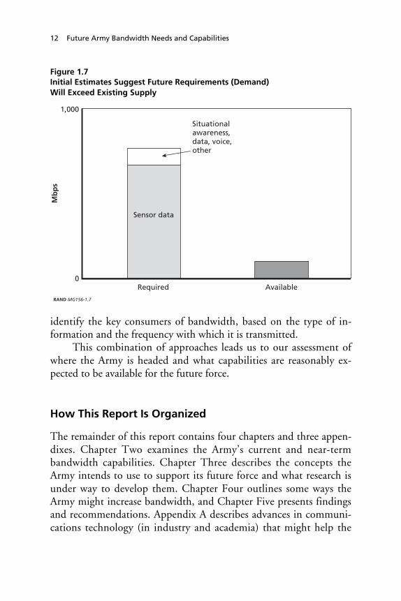
Initial assessments of future network bandwidth requirements,based on preliminary requirements documents of the future Army,highlight a gap between supply and demand. Figure 1.7 plots peakbandwidth requirements for the brigade-sized Unit of Action, as wellas expectations, based primarily on spectrum available today or ex-pected to be available in the near term. The shortfall is driven mainlyby sensor data needs. This is discussed further in Chapter Three.
Methodology
The general methodology employed for this study consisted of acombination of approaches, including literature reviews of both pub-lic and government documents, interviews with key governmentcontractors and other Army personnel, and data analysis of the per-formance capabilities of certain communication technologies. Becausethe Army’s future force concepts remain fluid, we used informationand data collected during past Army digitization exercises, data oncommercial devices, modeling and simulation estimates of futureperformance, and extensions of near-term Army plans and require-ments. Specifically, we examined the operational architectures of theStryker Brigade Combat Team and the Future Combat System to
12 Future Army Bandwidth Needs and Capabilities
Figure 1.7Initial Estimates Suggest Future Requirements (Demand)Will Exceed Existing Supply
RAND MG156-1.7
0
1,000
Required Available
Sensor data
Situational awareness, data, voice, other
Mb
ps
identify the key consumers of bandwidth, based on the type of in-formation and the frequency with which it is transmitted.
This combination of approaches leads us to our assessment ofwhere the Army is headed and what capabilities are reasonably ex-pected to be available for the future force.
How This Report Is Organized
The remainder of this report contains four chapters and three appen-dixes. Chapter Two examines the Army’s current and near-termbandwidth capabilities. Chapter Three describes the concepts theArmy intends to use to support its future force and what research isunder way to develop them. Chapter Four outlines some ways theArmy might increase bandwidth, and Chapter Five presents findingsand recommendations. Appendix A describes advances in communi-cations technology (in industry and academia) that might help the

Introduction 13
Army address its bandwidth problem. Appendix B contains a surveyof some of the routing protocols being considered for mobile ad hocnetworks. Appendix C describes some of the ongoing activities ad-dressing communications of a mobile user environment.


15
CHAPTER TWO
Current and Near-Term Capabilities
This chapter assesses the current and near-term requirement forbandwidth and the Army’s capability to meet that requirement. Itfocuses on digitized forces, such as the Stryker Brigade Combat Team(SBCT), and on programmed system capabilities. It assesses demandin two ways: based on an analysis of information exchange, and basedon data from field experiments. The discussion then turns to ananalysis of how current and near-term systems support existing de-mands for capacity.
Needs Based On Information Exchange Requirements
We have examined the Combined Arms Center Army Battle Com-mand Common Operational Architecture1 (CACACOA 3.1) to lookfor trends and major consumers of capacity for the SBCT. Informa-tion flows (information exchange requirements) were categorized ac-cording to their support of command, operations, administra-
____________1 Quoting: “The CACACOA is a collection of operational architecture products that is basedon the Army Universal Task List (AUTL) and the Universal Joint Task List (UJTL), thatdescribes detailed tasks, activities, and information exchanges that occur within and amongArmy Units from Echelon Above Corps (EAC) to Company and below. Additionally, theCACACOA describes Army interactions with Joint and Coalition forces in the support ofstrategic and operational tasks. CACACOA is used to support the definition and validationof common operational requirements” (http://simci.army.mil/ds/dscgi/ds.py/ViewPropos/File-301).

16 Future Army Bandwidth Needs and Capabilities
tion/logistics, intelligence, fire support, and engineering. Using thesecategories, key consumers were identified based on the volume of in-formation and the frequency with which it is transmitted.
• The greatest consumers appear to be database updates andtransfers and sensor data. These are both voluminous and fre-quent. Note, however, that database and compression technolo-gies have the potential to reduce these needs. User needs will af-fect the required quality of the data, which in turn affects thedegree of compression used.
• The next greatest consumers are probably intelligence users, ei-ther imagery or electronic. These can be large databases but areupdated only a few times per day.
• Vehicle position reports are, by far, the most frequent informa-tion passed and involve the greatest number of users. Any onereport, however, is fairly small in message size.
A summary of our analysis appears in Table 2.1. These estimatesare based on a best bottom-up effort to estimate demand. Althoughthey are useful, it is important to realize that unanticipated needs canvastly increase the actual requirements. In addition, these estimatesare for static or average situations that do not capture the dynamics ofinformation flow during an operation.
Table 2.1Characterization of SBCT Information Flow from CACACOA 3.1 Data
Capacity DemandVersus Frequency ofCommunications Less Frequent More Frequent
Smaller capacity Personnel status (6 times perday), other administrative/logistics (1–2 per day)
Voice, combat vehicleposition (240 times per day),other vehicle position(96 times per day)
Higher capacity Intelligence databases fromexternal sources, e.g., battledamage assessment (4 timesper day)
Common operational picture(96 times per day), sensordata (144 times per day)

Current and Near-Term Capabilities 17
Needs Based on Experimental Measurements
An alternative to bottom-up estimation (from information exchangerequirements) is to use actual field data, either from real operations orfield experiments. Figure 2.1 shows data volumes as measured duringthe 1997 Division Advanced Warfighting Experiment (DAWE)2
conducted at Fort Hood, Texas, by the 4th Infantry Division. The
Figure 2.1Brigade Communications Usage During DivisionAdvanced Warfighting Experiment
1024
2048
Kilo
byt
es p
er s
ec
Situationalawareness
Collaborativeplanning
Precision engagement
Focused logistics
256
1.7 Mb required
MSE tech insertion
MSE
Fiber optics during DAWE allowed for all communications
RAND MG156-2.1
____________2 The DAWE was designed to exhibit the performance and potential for a large number ofsystems. For that reason, communication was basically unlimited, with nodes connected byfiber optic cable. While this is artificial, the detailed measurements do show where commu-nications might have limited information flow.

18 Future Army Bandwidth Needs and Capabilities
capacity demands in this figure are at the brigade level over a 24-hourperiod with a breakdown according to the supported functions. Thecapacity demands shown in Figure 2.2 are at the division level. Spe-cifically, the peak demand at the brigade level was 1.7 megabits persecond (Mbps), and the peak communication demand at the divisionlevel is three times higher, at 5.1 Mbps.
The data from this warfighting experiment should indicate de-mands that change according to the phase of the battle (e.g., plan-ning, preparation, main attack, counterattack, consolidation) andtime. The data shown in Figure 2.2 are different from Figure 2.1 notonly by the division level, but also by the instantaneous data thatcapture the dynamics of information flow over a few hours. Thevariation shown indicates an opportunity to “smooth demands” de-
Figure 2.2Variations in Operational Bandwidth Demands in DAWE(Minus Data from Intel and Log Units)
VoiceNetwork cost (TCPIP+ATM +FEC)ISYSCONDMS
FBCB2
Aviation FLIRS
ABCSACTTelemedicineCollaborativeplanning
BVTC0
1
2
3
4
5
6
Meg
abit
s p
er s
eco
nd
1 7 13 19 25 31 37 43 49 55 61 67 73 79 85 91 97 103
109
115
Time (minutes)
Preparation
LD/LC
Main attack Counter attack
Consoli- dation
5.1 Mbps required
Intel?Log?
Planning
RAND MG156-2.2
SOURCE: U.S. Army Signal Center.

Current and Near-Term Capabilities 19
pending on the situation; there is a factor of five with respect to thevariation from peak demand to lowest bandwidth demand. Clearly,there is an opportunity to prioritize and smooth flow throughout thenetwork.
While in some ways reflecting dynamic needs, the DAWE waslimited (as are all field experiments) by artificialities and peculiaritiesof the experiment as played by the forces. Command post exercisesalso are artificial in that play typically moves faster than it does inactual operations, and thereby increases needs for communicationsrates. The DAWE was designed to exhibit the performance and po-tential for a large number of systems. Nonetheless, these DAWE re-sults, which show demands of 2.1 and 5.1 Mbps for the battalion-and division-level command posts, do roughly correspond to otherstudies of existing demand. The Congressional Budget Office (2003)cites studies by Mitre that estimate current peak demand usage to beapproximately 1, 3, and 7.5 Mbps for the battalion-, brigade-, anddivision-level command posts respectively. A qualitative assessment3
of the Army’s AWEs (in 1997 and 1998) describes a general poorperformance of the communication networks.
Supporting Needs: Current and Near-Term Systems
Table 2.2 shows the systems that transmit the information character-ized previously. The table uses the system architecture developed forthe SBCT to show the number, variety, and diversity of communica-tions networks at brigade level.
These networks are organized along functional lines, with differ-ent participants using different systems. As an example, the table
____________3 According to the Congressional Budget Office (2003), quoting: “The Army’s advancedwarfighter experiments conducted at the National Training Center in 1997 and 1998 were,respectively, battalion- and brigade-level experiments using state-of-the-art communicationsequipment. The AWEs reveal bandwidth problems and network failures to the point wheresoldiers switched back to analog voice communication.”

20 Future Army Bandwidth Needs and Capabilities
Table 2.2SBCT Information System Architecture
Purpose of NetType of
CommunicationsNumber of
Users
Command HF, voice 17Situation/command and control SINCGARS, data 10Army Battle Command System (ABCS) Data NTDR, data 34Operations and intelligence SINCGARS, voice 31Situation/command and control EPLRS, data 71Command SINCGARS, voice 33Administration/logistics SINCGARS, voice 20Fire support SINCGARS, voice 10
Total 226
NOTE: Only brigade-level networks are shown.
shows the brigade-level networks for the first SBCT. Eight networksoperate at this echelon, supporting command, situation/C2, databasesharing (Army Battle Command System), administration/logistics,and fire support. The networks use a variety of radio systems: single-channel ground and airborne radio system (SINCGARS), high fre-quency (HF), enhanced position location reporting system (EPLRS),or Near-Term Digital Radio (NTDR). Both voice and data areshared.
Information-sharing networks have the largest number of par-ticipants, with EPLRS having the largest at over 70 participants. Thisnetwork primarily shares position reports. The EPLRS network atbrigade links to other EPLRS networks at battalion. By contrast,command networks have fewer participants, reflecting use and im-portance.
Table 2.3 shows the capabilities of selected current and near-term Army communications systems that would support brigadeechelons. Currently, the NTDR replaces the Mobile SubscriberEquipment (MSE). NTDR, in turn, is being replaced by the TacticalHigh Speed Data Network (THSDN), which can pass 256 kbps cur-rently and has the potential to grow to 2 Mbps. Both systems requirestationary transmission nodes during operation.

Current and Near-Term Capabilities 21
Table 2.3Assessment of Current and Near-Term System Capabilities
System Mobility Max Throughput
Current/near term
Near-Term Digital Radio Stationary nodes 288 kbps (shared)
Tactical High Speed DataNetwork
Stationary nodes 256 kbps growing to2 Mbps
Far term(2007+)
WIN-T (new ORD) Mobile 256 kbps Blk 14 Mbps objective
JTRS (possible redirectionby DoD)
Mobile 2 Mbps Cluster 110 Mbps objective
NOTE: WIN-T will also pick up communications currently supported by single-purposesystems such as Trojan Spirit, adding 1.2 Mbps to the loading shown on Figure 2.1.
In the far term, the WIN-T and Joint Tactical Radio System(JTRS) will add both increased capacity and greater mobility. TheWIN-T Operational Requirements Document (ORD) is expected toalign with future force concepts of operations. DoD now proposesJTRS as a platform to replace all current tactical data links on thebattlefield.4 The spectral efficiency (i.e., the ratio of the transmissioncapacity to the allocated bandwidth) of JTRS, as shown in Figure 2.3,is an improvement over existing radios and is at a level that is com-patible with the latest commercial offerings. There exist advancedR&D efforts (see the subsection “BLAST” in Appendix A) that holdpromise of increasing spectral efficiency tenfold.
Finally, the note to Table 2.3 makes the point that data cur-rently passed by Trojan Spirit, an intelligence communications sys-tem, will be carried by WIN-T. This is an example of how the im-plementation of WIN-T will support multiple users, thus reducing
____________4 The Assistant Secretary of Defense, Networks and Information Integration (ASD [NII])(formerly the Assistant Secretary of Defense, Command, Control, Communications andIntelligence (ASD [C3I])), issued a June 17, 2003 memorandum amending the DoD RadioAcquisition Policy Memorandum of August 28, 1998, to require that all communicationssystems, including those operating above 2 GHz, be developed in compliance withJTRS/SCA.

22 Future Army Bandwidth Needs and Capabilities
Figure 2.3Spectral Efficiency of Various Radios
RAND MG156-2.3
0
0.2
0.4
0.6
0.8
1.0
1.2
1.4
1.6
1.8
2.0
Bit
s p
er s
eco
nd
per
Her
tz
Military and commercial radios and standards
EPLRS NTDRwide- band
SINCGARS NTDR narrow-
band
802.11b GSM JTRS (OFDM)
802.11a (OFDM)
redundancy in communications. It also indicates how the demand forWIN-T will continue to increase.
Summary and Conclusions
This chapter examined near-term demand and capabilities. Currentradios and networks (NTDR and THSDN) are far less capable thanthe newer radios and systems being developed (JTRS and WIN-T).The newer systems will support higher data rate transmissions andcommunication on the move.
Measurements from the DAWE indicate that demands for ca-pacity can easily reach and exceed 2–5 Mbps for the current digitizedforce, which would strain existing radio networks (NTDR andEPLRS) depending on how the network traffic is allocated. Thesemeasurements are taken in an exercise environment and hence repre-sent demands for only a narrow slice of a real operation. However, itis apparent that current and near-term systems will not meet capacity

Current and Near-Term Capabilities 23
or mobility needs of the current force. Far-term (2007+) systems willmeet the needs of the current force, but demands can also be ex-pected to grow in the interim. A Defense Science Board report(Howard, 2000) cited several sources5 when it estimated demand in2010 to be ten times today’s levels. (The data does show an opportu-nity to manage operational demands and thereby reduce peak needs.)
More experimentation is needed to understand the true needsand capabilities of current and interim systems in terms of the neces-sity of information requirements and the manner in which varioustypes of information contribute to mission success. At some levels,this is a sentiment shared within the Army signal community: “TheArmy has only fielded its first two SBCTs, and there are not enoughplanned training events to test the full employment of the command,control, communications, computers, intelligence, surveillance, andreconnaissance (C4ISR) and completely evaluate the commanders’ability to gain information superiority” (Toomey, 2003). Currently,there exists only a scant amount of data on the details of real-worlddemands and analysis of the necessity and value of proposed infor-mation flows at each of the various echelons.
With respect to analyzing information exchange requirementsversus analyzing data from experimentation, both approaches provideuseful insights, but neither is definitive. In general, estimates of futurebandwidth should consider both procedures and allow for consider-able variation and flexibility.
____________5 The C4ISR Mission Assessment Study from 1994, the JASON Global Grid Study from1992, and the Tactical Battlefield Communications Study from 1999.


25
CHAPTER THREE
Future Communication Needs andSystem Capabilities
This chapter examines future bandwidth needs and capabilities. Itbegins with a description of the Future Combat Systems concept,which is to be supported with an information grid composed of a lay-ered communication network (see Figure 3.1). Included in these lay-ers are (1) the terrestrial network that supports mounted troops, (2) aterrestrial network that supports dismounted troops, (3) an airbornenetwork of unmanned aerial vehicles (UAVs) and fixed-wing aircraftat various altitudes, and (4) a space-based network of satellites. Thechapter discusses communication challenges and opportunities ateach of these network layers. This will be followed by a brief discus-sion on the issues associated with interconnecting these layers. Thechapter concludes with a summary, which includes a projection of theemerging Future Combat Systems (FCS) communication concepts.
Future Combat Systems Concept
The Army’s FCS will form the building blocks for the future force.The FCS is envisioned to be a system-of-systems consisting of multi-function vehicles operating in concert. Ad hoc mobile communica-tion networks capable of near-instantaneous transmission of data,information, and orders will connect these vehicles and their parentunits. As depicted in Figure 3.1, the concept calls for a multipart in-formation grid—a space grid, airborne grid, and terrestrial grid—to

26 Future Army Bandwidth Needs and Capabilities
Figure 3.1Layers of the Infosphere
Space grid
Air grid
Forward deployed warrior
Terrestrial grid
Fiber PoP
Sanctuary
RAND MG156-3.1
SOURCE: DARPA.
connect space-air-surface platforms to facilitate information domi-nance. An FCS Unit of Action is a brigade-sized force composed ofthree combined arms battalions along with a “brigade” company(HHC), an aviation detachment (AVN), a forward support battalion(FSB), a non-line-of-sight battalion (NLOS Bn), and a C4ISR unit orbrigade intelligence company (BIC) (for network management andother signal functions). This organization is shown in Figure 3.2. Thefuture force will utilize multiple Units of Action.

Future Communication Needs and System Capabilities 27
Figure 3.2FCS Unit of Action
UA
HHC C4ISR FSBAVN
DET
RAND MG156-3.2
NOTE: The symbols in the figure reflect unit size. The “x” above the UA rectangle de-notes a brigade-sized unit. The symbol | above the HHC denotes a company-sized unit.The text “DET” above the AVN unit reflects that the aviation unit is a detachment. Thesymbol || above FSB reflects that it is a battalion-sized unit.
Future Needs
In the introduction to this report, Figure 1.7 highlighted the prelimi-nary estimates for bandwidth/communication-capacity and showedthe potential gap between supply and demand. It also pointed outhow sensor data dominates demand. A more detailed breakdown ofthis estimate of requirements is shown in Figures 3.3 and 3.4.Clearly, UAV sensors contribute the bulk of the requirements. Effortsto address shortfalls certainly require curtailing these requirements.On a unit basis, the UAV sensor data impacts the combined arms(CA) battalions of the Unit of Action. Figure 3.3 shows the relativebreakdown of bandwidth needs. A number of data types are distin-guished, including voice, situational awareness (SA) data, firing data,ground robotic controls and sensors, and UAV sensors. But the rela-tive magnitude of the UAV sensor data effectively creates two catego-ries of data, UAV sensors and all others. Figure 3.4 shows the break-down of demands within a Unit of Action.

28 Future Army Bandwidth Needs and Capabilities
Figure 3.3Unit of Action Bandwidth Requirements: Breakdown by Demand
Voice (<1%)
Collaboration (2%) Firing (1%)Situational awareness data (6%)
Robotic Control (ARV/MULE) (<1%)
Sensing: SUGV, UAV class I and II, UGS, LAM/PAM (18%)
Sensing: UAV class III and IV
(67%)
Sensing: Manned Ground Vehicle (6%)
RAND MG156-3.3
Figure 3.4Peak Requirements (Mbps) by Unit for the Unit of Action
Mb
ps
1
10
100
1,000
HHC C4ISR CA BnX 3
AvnDet
NLOSBn
FSB
RAND MG156-3.4

Future Communication Needs and System Capabilities 29
By examining the requirements documents,1 we can extrapolatecapacity demands. For the Unit of Action brigade (see Figure 3.4),the requirement suggests that peak and average capacity are on theorder of hundreds of megabits per second. Based on initial studies bythe Lead System Integrator (Boeing/SAIC) for the FCS, this is at leastdouble (and perhaps 10 times) what will be available given availablespectrum allocations (i.e., bandwidth). Thus, the shortfall betweenwhat is required and what is available is hundreds of megabits persecond for the Unit of Action brigade.
Challenges and Opportunities
The next several sections focus on needs and capabilities at the spe-cific network layers (soldier, terrestrial, air, space). Overall, the per-formance of many of the FCS communication technologies has yet tobe thoroughly tested for suitability with respect to FCS requirements.So, data are scarce. In lieu of such data, this report describes key vari-ables that affect the performance of these technologies. For conceptswhere commercial technologies are relevant, those technologies willbe described in terms of their performance.
Overall Terrestrial Network
Tactical communication networks, in a network-centric environment,will certainly be mobile and “ad hoc.” This is true for soldier net-works and also for the larger terrestrial networks supporting groundvehicles. Ad hoc networks are, by definition, self-configuring com-munication networks without any central controller. A large-scale, adhoc network of transmitting and receiving nodes is the objective forthe future C4ISR architecture for FCS and the future force.
____________1 TRADOC Pamphlet 525-3-90, Objective Force Maneuver Units of Action, Fort Monroe,VA: U.S. Army Training and Doctrine Command, November 1, 2002.
30 Future Army Bandwidth Needs and Capabilities
Terrestrial Network Challenges
Ad hoc networks do not rely on a fixed infrastructure, such as thatwhich a commercial cell phone network enjoys, e.g., there is no in-tent to use permanent towers to relay messages to and from other us-ers/nodes. The nodes of ad hoc networks themselves have to serve thispurpose, i.e., they have to store and forward each other’s data packetsmuch like today’s wired Internet. The amount and type of data trafficthese networks can support functionally defines their capacity.
The theoretical capacity limitations of mobile ad hoc networks(MANETs) continue to be investigated. Gupta and Kumar’s (1999)results, which assume the use of omnidirectional antennas, are as fol-lows: If we define capacity as the average rate of data transmissionbetween any two-networked nodes (in bits per second), then themaximum capacity per node (1) decreases2 as in n as n gets large in
a planar network, as shown in Figure 1.4, and (2) decreases as in n3
for a 3-D network. While such theoretical results are useful in termsof attempting to identify limiting parameters, communication net-work performance can be very sensitive to scenario specific assump-tions (i.e., terrain, mobility, vehicle sizes, weather, etc.).
In ad hoc networks, a message from a source node to a destina-tion node “hops” between intermediary nodes if necessary. This iswhy ad hoc networks are sometimes called “multihop” networks.However, these hops consume network capacity. The bigger the net-work in terms of nodes n, the longer the chains of hops that will takeplace (e.g., a 9-node network may average three hops between sourceand destination, a 16-node network may average four hops, a 25-node network will average five hops, etc.) The rub: there is a limit tothe number of capacity-consuming hops that can occur before thenetwork traffic grinds to a halt. Thus, there is a limit to the number
____________2 The paper by Gupta and Kumar (1999) shows capacity (of a fixed ad hoc network with
nodes n randomly placed) is O(1/ n ) bits per second on a per-node basis. In other words,throughput available to each node goes to zero as the number of nodes goes up. Their workassumed omnidirectional antennas and did not account for overhead message traffic.

Future Communication Needs and System Capabilities 31
of nodes in such a network. But using higher-data-rate radios to im-prove link capacities will help.
However, it is not just the hopping of data packets that contrib-utes to capacity utilization, but the overhead associated with routingthe data. Mobile ad hoc networks must “discover” appropriate routesfrom sender to receiver. As an example of how this need is addressed,there are a number of commercial protocols that rely on frequentbroadcasts to all network nodes to gain a picture of the network as itcontinues to change. But these protocols may not be appropriate inall situations (e.g., tactical environment or a congested network);protocols designed specifically for the Army may need to be devel-oped.
Terrestrial Opportunities: Factors Affecting Capacity inAd Hoc Networks
A number of key parameters affect the ability to transmit informationin a network of transceiving nodes. Some key factors include:
Message routing. Algorithms that discover routes for data pack-ets with fewer hops and without incurring much overhead will yieldrelatively higher capacities. Capacity (per-node) will still diminish asthe network size grows. But better routing could potentially changethe shape of the curve in Figure 1.4.
Power management schemes. Transmission power managementor “power-based routing” allows nodes to automatically either (1)increase power to get better range/connectivity, or (2) decrease powerto lower the possibility of interfering with another node’s transmis-sion.
Antenna technology. Directional antennas can focus their en-ergy to specific receivers, thus lowering the possibility of interferenceelsewhere in the network and also saving transmission energy for thenode itself.
Node mobility. Node mobility (i.e., acceleration, speed, prox-imity to other nodes, etc.) affects throughput in ad hoc networks.Wilson (2001) uses GloMoSim to examine the sensitivity of messagerouting to vehicle mobility. He observed that throughput went downwith increases in velocity when a small number of vehicles were in-
32 Future Army Bandwidth Needs and Capabilities
volved. Grossglauser and Tse (2001) observed an opposite effect intheir experiments that showed how mobility could improve connec-tivity and hence throughput. More experimentation and simulationare needed to examine how mobility impacts network performance.
Differences between measured and theoretical performance.The interaction of all these factors affects overall network perform-ance. Any performance estimate is therefore a function of numerousvariables whose values are neither established in a common scenarionor commonly defined. Users, thus, must carefully consider any net-work performance estimates as representing best-case conditions. Asan example of the differences between actual and theoretical maxi-mum data rates, Table 3.1 lists some protocols that have been used orare under development along with their theoretical and realistic datathroughputs.
Estimates of realistic maximum throughput are roughly one-third to one-half the stated maximum. These estimates are docu-mented in Dornan (2002):
The theoretical maximum capacity of 802.11b is 11 Mbps,which is often quoted by vendors and by groups such as WECA.It pushes wireless LANs through an important psychologicalbarrier, matching the speed of the original Ethernet standard.However, the number is misleading. It refers to the total physicallayer capacity, much of which is used by the protocol itself, so itis not actually available for data. The maximum data rate of an802.11b network is really only about 6 Mbps, and that can beachieved only under an optimum condition—over a short rangeand with no interference. It quickly drops when packet collisionsor other errors occur. A 50% error rate will reduce the real-throughput by about two-thirds to only 2 Mbps.
Table 3.1 identifies commercial-off-the-shelf (COTS) conceptsthat suggest that terrestrial and soldier networks3 seeking link
____________3 Soldier networks are those networks that support the need for dismounted infantry to ex-change voice and data. ITT Industries has demonstrated the Soldier Level Integrated Com-munications Environment (SLICE), a mobile computer with a headset display and micro-
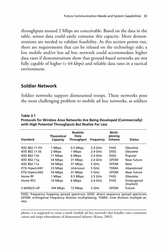
Future Communication Needs and System Capabilities 33
throughputs around 2 Mbps are conceivable. Based on the data in thetable, sensor data could easily consume this capacity. More demon-strations are needed to validate feasibility. As this section points out,there are requirements that can be relaxed on the technology side; aless mobile and/or less ad hoc network could accommodate higherdata rates if demonstrations show that ground-based networks are notfully capable of higher (> 64 kbps) and reliable data rates in a tacticalenvironment.
Soldier Network
Soldier networks support dismounted troops. These networks posethe most challenging problem to mobile ad hoc networks, as soldiers
Table 3.1Protocols for Wireless Area Networks Are Being Developed (Commercially)with High Potential Throughputs But Realize Far Less
StandardTheoretical
Capacity
RealisticData
Throughput Frequency
Multi-plexingScheme Status
IEEE 802.11-FH 1 Mbps 0.5 Mbps 2.4 GHz FHSS ObsoleteIEEE 802.11-SS 2 Mbps 1 Mbps 2.4 GHz DSSS ObsoleteIEEE 802.11b 11 Mbps 6 Mbps 2.4 GHz DSSS PopularIEEE 802.11g 54 Mbps 31 Mbps 2.4 GHz OFDM Near futureIEEE 802.11a 54 Mbps 31 Mbps 5 GHz OFDM NewETSI HiperLAN1 23 Mbps Unknown 5 GHz TDMA AbandonedETSI HiperLAN2 54 Mbps 31 Mbps 5 GHz OFDM Near futureHome RF 1 Mbps 0.5 Mbps 2.3 GHz FHSS ObsoleteHome RF2 10 Mbps 6 Mbps 2.4 GHz FHSS Endangered
(market)5-WING/5-UP 104 Mbps 72 Mbps 5 GHz OFDM Future
FHSS: frequency hopping spread spectrum; DSSS: direct sequence spread spectrum;OFDM: orthogonal frequency division multiplexing; TDMA: time division multiple ac-cess.
________________________________________________________phone; it is supposed to create a mesh (mobile ad hoc network) that handles voice communi-cation and maps whereabouts of dismounted infantry (Krane, 2002).

34 Future Army Bandwidth Needs and Capabilities
are mostly dispersed into surrounding terrain and equipped with ra-dios with limited capabilities. Soldier networks cannot be comparedto commercial products connecting mobile users, as soldier networkswill not be able to use an existing fixed infrastructure nor will theyoperate in the open. Soldier networks thus present a unique set ofchallenges and opportunities, as described in this section.
Soldier Network Challenges
The soldier network is a subnet of the terrestrial network. The mostbasic communication requirements for dismounted soldiers are toknow (1) their own location, (2) the location of friends, and (3) thelocation of enemies. Transmission power and antenna size will belimited to what can be practically worn and battery-powered. Inbuildings, tunnels, and similar locations, geolocation via GPS is ex-tremely limited. Nonetheless, the subnet of dismounted troops willbe required to maintain connectivity to the main terrestrial networkand/or the information grid in general.
Soldier Network Opportunities: New Programs and Systems
A Defense Advanced Research Projects Agency (DARPA) program tosupport soldier communication called Small Unit Operations Situa-tion Awareness System (SUO SAS) was concluded in fall 2002 withsuccessful demonstrations of the ability of dismounted soldiers tomaintain communication connectivity in challenging environments.Radio ranging with accuracy of four meters was also demonstrated.SUO SAS program goals4 were to develop radio systems that can pro-vide the dismounted soldier the critical situational awareness re-quired. CERDEC (the CECOM Research, Development, and Engi-neering Center) is funding continued development in this area underthe Soldier Level Integrated Communications Environment (SLICE)program.
____________4 As part of this effort, ITT was to develop a 4 Mbps software radio with ranging capabilities.This work continues under CECOM funding. SUO SAS has been demonstrated. SLICEwill not be demonstrated until summer 2004.

Future Communication Needs and System Capabilities 35
More broadly, key objectives of the research program includedevelopment of the following: (1) radios that supported mobile adhoc networking, and (2) software and hardware to facilitate continu-ous position/navigation and ranging ability, as well as tools that cansmartly manage5 the amount and type of information being displayedto individual soldiers. Connecting the soldier subnet to the info gridmay require airborne relays, space-based relays, or both.
Airborne Networks
The preceding sections discussed some of the difficulties with terres-trial communications. One solution to improve performance is to usean airborne or satellite-based element in the network. This adds con-nectivity to users who might be separated from other nodes (becausethey are out of range and/or out of sight) and also eases difficulties inrouting messages through the network. Satellite nodes are discussedin a later section.
Airborne Network Layer Challenges
An airborne layer can provide connectivity over rough terrain forsituations where ground-to-ground communication is difficult (e.g.,poor line of sight, etc.). Greater connectivity in a network can pro-duce additional capacity-carrying links. In this manner, the UAV as a“vertical node” is a capacity multiplier. One of the key challengeswith respect to relying on UAVs as vertical nodes is the number re-quired to provide a given force size with assured connectivity. Thereis also the potential that such an airborne node can unintentionallylimit message traffic, e.g., “exposed terminal problem” (see Karn,1990).
____________5 The intent of the developers was to embed an information management system that “usesknowledge of soldiers’ locations and missions to automatically route the right information tothe right user at the right time” (SRI, 2001).

36 Future Army Bandwidth Needs and Capabilities
Airborne Network Opportunities: Adding a Vertical Node
Vertical nodes can reduce message routing duties and message routingoverhead for tactical networks. Specifically, vertical nodes can be po-sitioned to acquire routing information with fewer disruptive blanketinterrogations (i.e., broadcasts) of the entire neighborhood of net-work nodes.
Social network analysis says that a very small number of mobile“agents” among a group can improve the information-exchange abil-ity of the entire group.6 This is called the “small-world” concept or“small-world” phenomenon. Work by Helmy (2002, 2003) extendedthis social network result to communication networks and MANETsas well as fixed sensor networks. His analysis consisted of simulationexperiments of 1,000 nodes over a square kilometer. His observationof the effect of the creation of a small number of additional networkpaths was that it reduced the average path length for network mes-sages (e.g., number of hops reduced). Quoting Helmy from Patch(2002): “In a network of 1,000 nodes and around 5,000 links, adding25 to 150 links achieves 40 to 60 percent reduction in path length.”We apply this observation later in this report to analyze throughputimprovements for a given number of vertical nodes.
Essentially, the use of “contacts” (or short-cut-providing nodes)amounts to another layer on top of a flat network, hence a multilayernetwork structure with vertical nodes. The small-world contact nodeis essentially a MANET backbone node or a vertical node. (Thechoice of the node to serve in this role is based on its coverage andcould be dynamically picked or designated in advance.) It is easy toenvision a fleet of airborne relay nodes serving as dedicated shortcuts,
____________6 Quoting a survey by Sanchez and Chowell-Puente (2001): “Watts and Strogatz knew thatregular networks have longer path lengths and larger clustering coefficients (a measure of thefraction of a node’s links that go to other nodes in its immediate vicinity) than random net-works. However, they noticed that the replacement (with low probability) of a few localconnections with long-term connections drastically decreases the average-path length whilekeeping high levels of clustering . . . Watts and Strogatz showed that the replacement of onepercent of the connections of a regular network with distant links was enough to triggersmall-world phenomena.”

Future Communication Needs and System Capabilities 37
i.e., an upper layer as shown in Figure 1.5. More study is needed todetermine the ideal ratio of vertical (or contact nodes) to the othernetwork nodes.
Space Networks
Airborne platforms are subject to weather, and they require some de-ployed infrastructure to support operations. Satellites are globallyavailable, are in place for support, and add the advantages to a terres-trial network of an airborne node. They pose a different set of op-portunities and challenges, as discussed in this section.
Space Network Challenges: Limitations of Optical Links
The Transformational Communication Architecture (TCA) proposesa space grid that uses laser communications to meet future capacityrequirements. As Figure 3.5 shows, absolute capacity requirementsnow and in the future are measured in the gigabits per second.
Figure 3.5Capacity Challenges for DoD as of June 2002
Gb
ps
RAND MG156-3.5
Projected future requirements
1.9
29.7
53.9
137.5
0
40
80
120
160
Current capacity
2010 2015 2020
SOURCE: Haven (2003).
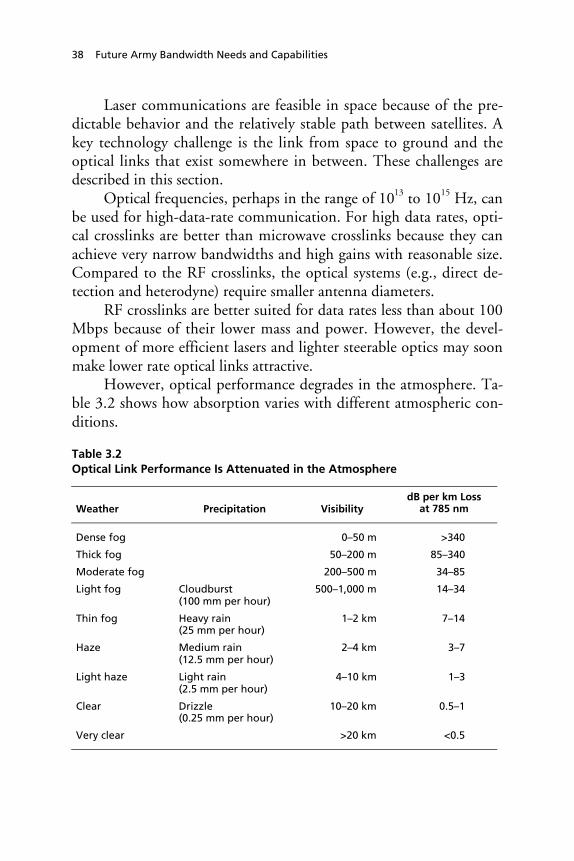
38 Future Army Bandwidth Needs and Capabilities
Laser communications are feasible in space because of the pre-dictable behavior and the relatively stable path between satellites. Akey technology challenge is the link from space to ground and theoptical links that exist somewhere in between. These challenges aredescribed in this section.
Optical frequencies, perhaps in the range of 1013 to 1015 Hz, canbe used for high-data-rate communication. For high data rates, opti-cal crosslinks are better than microwave crosslinks because they canachieve very narrow bandwidths and high gains with reasonable size.Compared to the RF crosslinks, the optical systems (e.g., direct de-tection and heterodyne) require smaller antenna diameters.
RF crosslinks are better suited for data rates less than about 100Mbps because of their lower mass and power. However, the devel-opment of more efficient lasers and lighter steerable optics may soonmake lower rate optical links attractive.
However, optical performance degrades in the atmosphere. Ta-ble 3.2 shows how absorption varies with different atmospheric con-ditions.
Table 3.2Optical Link Performance Is Attenuated in the Atmosphere
Weather Precipitation VisibilitydB per km Loss
at 785 nm
Dense fog 0–50 m >340
Thick fog 50–200 m 85–340
Moderate fog 200–500 m 34–85
Light fog Cloudburst(100 mm per hour)
500–1,000 m 14–34
Thin fog Heavy rain(25 mm per hour)
1–2 km 7–14
Haze Medium rain(12.5 mm per hour)
2–4 km 3–7
Light haze Light rain(2.5 mm per hour)
4–10 km 1–3
Clear Drizzle(0.25 mm per hour)
10–20 km 0.5–1
Very clear >20 km <0.5

Future Communication Needs and System Capabilities 39
In clear conditions, with visibility of 20 kilometers or better,atmospheric attenuation of about 0.5 dB/km is similar to the at-tenuation of single-mode fiber optic cable. In haze, with visibility of 4kilometers, the attenuation is about 3dB/km, which is similar tomultimode fiber.
Visibility in clouds ranges from 15 to 150 meters, makingclouds comparable to dense or thick fog. The cumulonimbus cloudsin thunderstorms can be as much as 10 kilometers high. Trying topass an optical signal through such a cloud could result in extremelyhigh attenuation (Kim, McArthur, and Korevaar, 2001).
Space Network Opportunities: New Technologies and Systems
Department of Defense activities. The TCA is being developed byNSSA (National Security Space Architect) to increase Department ofDefense communications capacity. The TCA is a result of the trans-formation communication study that proposed an increasedintersystem connectivity via optical crosslinks.
Figure 3.6 shows a notional system diagram for the TCA. Thecurrent plan is to put in place a laser communications backbone on asatellite system in geostationary orbit that would interface throughradio frequency communications with warfighters worldwide.
The TCA affords the Army an opportunity to gain access tohigh-capacity (multiple gigabits per second) communications, cer-tainly important for communications at theater and national eche-lons. Current plans for TCA will establish a global network beginningwith fiber optic–based and proceeding to satellite-based optical sys-tems. The RF link to tactical users, though, remains to be definedand funded.
Commercial activities. Free Space Optical (FSO) links have beenused for high-bandwidth communication between buildings. Com-mercial systems for this purpose are typically rated by their maximumrange in hazy conditions, and typical ranges are 1,000–4,000 meters.In thick fog, a 4,000-meter system is usable for up to 440 meters. Indense fog, it is usable for up to 140 meters. Clearly, systems of thisclass cannot communicate through thick clouds.

40 Future Army Bandwidth Needs and Capabilities
Figure 3.6Proposed TCA Increases Cross-link Capacity Using Optical and RF Links
Different wavelengths are affected differently by atmosphericconditions. Therefore, transmitting the same information in morethan one wavelength increases the chance that the information willget through on at least one channel. For example, in light fog there isless scatter in the infrared than in the visible spectrum. In addition,noise levels (such as solar background noise) also vary across thespectrum.
Most applications of multispectrum optical communication areusing additional wavelengths to increase capacity of the link. If, in-stead, the extra bandwidth is used to transmit redundant information,the extra capacity can be traded off for improved signal-to-noise ra-tios.
Another mechanism to address the problem of atmospheric tur-bulence is to transmit several beams (not necessarily on differentwavelengths) that are physically displaced. Because each of thesebeams will experience different turbulence cells in the atmosphere, itis more likely that at least one will be experiencing quiescence at anygiven time.

Future Communication Needs and System Capabilities 41
While the ranges of these commercial systems are limited, theycould be used to support selected high-capacity needs in a nonmobilescenario. These results illustrate, however, the difficulty of using opti-cal systems near the ground in low parts of the atmosphere.
Network Architecture: InterconnectionsAmong the Layers
Developing an architecture for a layered communication network is acomplex undertaking. Under contract to ASA(ALT), Johns Hop-kins/Applied Physics Laboratory assessed alternative communicationarchitectural topologies for the FCS, based on a bottom-up estimateof information exchange requirements. Interim reports from thisstudy effort suggest a layered, hierarchical communication networkthat relies heavily on directional antennas and UAVs as communica-tion relays. Other studies by the FCS Lead System Integrator (Boe-ing/SAIC) are ongoing to assess the degree of hierarchical structureneeded to meet the information exchange needs of the FCS. Thus,this remains an open issue. The choice of architecture could have asignificant effect on bandwidth needs and capabilities.
Specifically, Johns Hopkins University (2002) recommended athree-level hierarchical network consisting of a main network ofnodes for the Unit of Action, which supports subnetworks that caninterface through any of the Unit of Action nodes. Units of Actioninterface with each other through gateway nodes at the Unit of Em-ployment layer, which acts as a hub. Quoting (Hillman et al, 2002):“A flat architecture at the lowest echelons exploits mobile ad hocnetworking with directional antennas for terrestrial communica-tions.” According to the report, company-sized units would eachneed at least 2 UAV relays centrally located above them.
As an aside, the authors of the Johns Hopkins University studyarrived at the following general findings: (1) unprocessed sensor dataare the major data source on the network, (2) image compressiontechniques can reduce capacity demands, (3) the communication de-mand from robotic vehicles is terrain-dependent, (4) omnidirectional

42 Future Army Bandwidth Needs and Capabilities
communications cannot achieve necessary link ranges and directionalantennas will be needed, and (5) terrestrial line-of-sight communica-tion will not be sufficient and UAVs and satcom relays will be crucial(Hillman et al., 2002).
Summary and Conclusions
This chapter examined far-term capabilities and needs based onspecification of the FCS and future force. Tiered, hierarchical archi-tectures that use airborne and/or satellite-based systems will have tobe employed. Pure terrestrial systems will probably not provide theconnectivity required in dispersed operational employments. TheArmy envisions future systems that involve a multitiered backbone,from the ground up to space, which will compose the Global Infor-mation Grid (GIG). This implies a large degree of complexity.
Capabilities at each of the layers (terrestrial, airborne, and space)were considered by looking at the devices and networks being pro-posed by DARPA and others. The GIG may have to support datarates as high as hundreds of gigabits per second. At the tactical,ground level, the data rate need could be hundreds of megabits persecond. Raw sensor data (from UAVs) are major contributors to theserequirements. It is not clear, given existing spectral allocations, thatthese rates are supported by the envisioned hardware and softwareconcepts for the near term. The required sensor usage envisioned forthe future force is so large that it can be said that data needs fall intotwo categories: (1) those generated by sensors (very high volume) and(2) those for command and control, situational awareness, and voicetraffic. Constant, iterative analysis will be required to determine dataneeds from among the data demands specified.

43
CHAPTER FOUR
Ways to Increase Capacity
Three general approaches to increase network capacity are as follows:(1) get the most out of the hardware and software, i.e., use improvedradios and antennas and make better use of allocated spectrum; (2)get the most out of the network’s architectural options, e.g., employhierarchical schemes using vertical nodes; and (3) look for ways tokeep and trim capacity demands down to what is needed.
Table 4.1 presents a categorization of ways to increase capacityalong with rough estimates (some are speculative) of the relativebenefits that might be achieved. It is not clear that combinations oftechniques produce cumulative gains in all cases. Some techniquespromise relative improvements of an order of magnitude or less. Oth-ers promise improvements of perhaps up to two orders of magnitude(e.g., directional antennas). Finally, some techniques hold the poten-tial for several or more order-of-magnitude improvements in capacity(e.g., compression and fusion).
Increasing Capacities of Links
Increasing the capacity of individual links can be accomplished byaccess to higher-frequency bands. Figure 4.1 highlights the currentmilitary use of communications spectrum. Most of the use is at thelower frequencies that are currently crowded by legacy systems. Mili-

44 Future Army Bandwidth Needs and Capabilities
Table 4.1Techniques to Increase Bandwidth
Technique Specifics and Potential Improvements
Increase capacities of links Higher frequencies and optical frequencies(×10), frequency reuse and spectral-efficientradios (×2–20), directional antennas (×2–300)
Improve routing efficiency Use new protocols for ad hoc networks, i.e.,smarter routing and/or node aggregation andclustering (×2–10)
Add a vertical element Airborne or satellite increases connectivity/decreases network load (×2–4)
Adjust needs of applications Incorporate communications into databasearchitecture (JCDB); data compression andfusion (multiple orders-of-magnitudeimprovement)
Manage bandwidth operationally Treat bandwidth as a limited operationalresource (×3–5)
tary uses, however, can conflict with commercial interests in spec-trum; foreign and U.S. commercial interests also have made alloca-tions in these bands scarce.
Currently, commercial mobile users are not planning to usehigher frequencies. DARPA is developing FCS communications sys-tems around 38 GHz, which provides increased inherent bandwidthand improved low probability of detection and intercept, but whichcomplicates antenna design.
Efficient use of frequency allocations can also improve capacity.Figure 4.2 illustrates a plot of measured spectrum occupancy col-lected over 43 minutes using an elevated (50-foot) antenna for recep-tion in an urban area. Note the variations in receiver power and thenoticeable slices of unused spectrum. The figure shows that adaptivespectrum management can increase capacity by more efficient use ofspectrum.

Ways to Increase Capacity 45
Figure 4.1Military Can Use Higher Frequencies
SINCGARSEPPLRS
NTDRGRC-227
HCLOSHave Quick
MSRTTactical PCS
MILTAR/SMART-T/SCAMPGBS
UFO/SPITFIREIRIDIUM
GPSGrenadier BRAT
RAND MG156-4.1
Spectrum
Communications Systems VHF UHF SHF EHF
30 MHz 300 MHz 3 GHz 30 GHz 300 GHz
SOURCE: CECOM. Used with permission.
Figure 4.2Fixed Spectrum Assignments Lead to Inefficient Utilization
SOURCE: Horne (2003). Used with permission.

46 Future Army Bandwidth Needs and Capabilities
Reuse can be accomplished with the use of existing wirelesswaveform applications with either automated adaptive approaches orreassignment of channels by the military commanders. The DARPAXG program aims to seek technologies that provide relative im-provements on the order of 10–20 times the capabilities of conven-tional radios (see Appendix C).
Utilizing Directional Antennas
Omnidirectional antennas transmit and receive in all directions. Forcommunication between a specific sender-receiver pair, this is a wasteof energy and causes unwanted interference with other transmittersand receivers that are nearby. The concept of directional antennas isthat the beam of the transmission is more focused, i.e., “less energy inthe wrong directions, more energy in the right directions.” Direc-tional antennas improve routing efficiency by focusing networkrouting along uncongested routes and by reducing redundant flows inthe network.
Two categories of directional antennas are switched beam andsteered beam. In a switched beam arrangement, the antenna is madeup of multiple, predefined narrow beams so that individual beamscan be selected. Switched beam antennas can be made cheaply andsmall (Ramanathan, 2003). A steered beam antenna has a single mainlobe that can be redirected, i.e., an algorithm steers a main lobe andnulls (Jain, 2003). A steered beam is more complex but performsbetter than a switched beam.
Gupta and Kumar (1999) show that network capacity does notscale well and that, at best, per-node capacity is O (1/ n ). This theo-retical result does not take into account directional antennas. A recentpaper by Yi, Pei, and Kalyanaraman (2003) calculates the capacityimprovements from using directional antennas, relative to a networkthat uses omnidirectional antennas. For a random network, they
prove that the relative gain from using directional antennas is
2πα
if
just the sender or the receiver relies upon a directional antenna of

Ways to Increase Capacity 47
beamwidth α. If both the senders and receivers of data utilize direc-tional antennas, the relative improvement is
4παβ
, where α and β are
the beamwidth (in radians) of the sender and receiver respectively.Table 4.2 provides a number of example calculations. It is observedthat greater gains come with narrow beamwidths. However, the morenarrow the beamwidth, the more technically difficult network rout-ing becomes, especially in a mobile environment; i.e., a narrow beamdoes place a greater burden on the protocol/radio to have accurateknowledge of the physical location of other radios. The DARPA FCSCommunications Program has been conducting tests and demonstra-tions using directional antennas.
Advantages and Disadvantages of Directional Antennas
The advantages of directional antennas are as follows:
1. Increased gain and thus longer range, which could lower thenumber of hops required and lower end-to-end latency;
2. Less interference and thus more spatial reuse, implying higher ag-gregate capacity;
3. Higher signal to noise ratio (SNR), implying better connectivity;4. Better information assurance: narrower beamwidth, implying
better security from interceptions, and better tolerance to jam-ming due to “nulling” capability (Ramanathan, 2003).
Table 4.2Relative Capacity Gains from Using Directional Antennas
SenderBeamwidth(degrees)
ReceiverBeamwidth(degrees)
RelativeCapacity
Improvement
20 20 324
30 30 144
90 90 16
20 omni 18
30 omni 12
90 omni 4

48 Future Army Bandwidth Needs and Capabilities
One potential disadvantage is that the longer range could inad-vertently interfere with a distant radio; power control would addressthis issue. Also, directional antennas add cost and complexity, espe-cially for very narrow beamwidths.
Simulation Results Using Directional Antennas
Theoretical results are useful because they indicate how much pro-gress can be made in terms of this technology. Simulation experi-ments with directional antennas tend to be more specific about typeof protocol and contention scheme used. To date, simulation experi-ments with directional antennas show only modest improvements.Therefore, more development is required to achieve the gains thathave been shown to be theoretically possible.
Ramanathan (2003) reports on OPNET simulations1 of a net-work using directional antennas (steerable); relative throughput im-provements were reported to be between 70 and 370 percent. Rama-nathan observes that power control is important in terms ofharnessing maximum performance improvements.
Sanchez (2002) reports simulation2 results on relativethroughput improvements. Table 4.3 shows ranges of how muchmore data are likely to get through the network with directional ver-sus omnidirectional antennas. Sanchez varied network density: net-
____________1 OPNET is a commercially available network simulator. Ramanthan (2003) describes thesimulations as a 20-node “highly loaded” ad hoc network running UDAAN protocols (thatintegrate power control) and assuming steerable antennas with both transmit and receivebeamforming. UDAAN (Utilizing Directional Antennas for Ad hoc Networking) is a projectsponsored by DARPA under the Future Combat Systems Communications program. “Asignificant payoff from UDAAN will be increased effective capacity. Other payoffs includedecreased packet latency, increased connectivity, greater multicast efficiency, and lower prob-ability of detection/interference.” See http://www.ir.bbn.com/projects/udaan/udaan-index.html.2 Experiments by M. Sanchez (2002) varied the CSMA/CA contention scheme by changingassumptions on whether the sender and receiver use directional antennas (for data or over-head messages associated with data transfer). His results showed that the most aggressivescheme in terms of utilizing directional antennas whenever possible work best. Power controlwas not integrated into the scheme.

Ways to Increase Capacity 49
Table 4.3Throughput Improvements for Two NetworksUsing Directional Antennas
AntennaBeamwidth 90 degrees 60 degrees 30 degrees 10 degrees
Network A 29–64% 43–107% 86–143% 56–186%
Network B 6–26% 17–39% 72–100% 17–145%
work A was made to be more sparse than network B. Power controlwas not incorporated into his scheme.
Improving Routing Efficiency
Effective routing schemes can use the network more efficiently, re-ducing redundancy in routing packets and excess overhead. Some es-timates of benefits from academic research on advanced schemesshow improvements of factors (delay and packet delivery ratio) up toan order of magnitude when compared with existing concepts(Blazevic, Le Boudec, and Giordano, 2003). Routing protocol devel-opment is an active area of investigation within the academic andcommercial sectors, and there are gains that can be achieved by con-tinuing to develop/refine routing protocols. Appendix B provides adescription of alternative schemes.
Adding a Vertical Element
The inherent constraints on capacity for a flat network can be dealtwith by making them “unflat,” i.e., creating islands of flat subnet-works that are smaller and interact with another layer of nodes. Themultilevel structure allows the islands to cross communicate via“backbone” nodes, which could be UAVs. An issue is how adaptivesuch structures can be, i.e., can they easily be formed ad hoc, or willthey require static preconfiguration? Obviously, an ad hoc formationability is desired, but more test and demonstration is needed.

50 Future Army Bandwidth Needs and Capabilities
A mobile airborne node is conceptually ideal as a vertical node.In a hierarchical architecture, it can lead to better routing, i.e., it canbe positioned to acquire routing information with fewer (disruptive)blanket interrogations (i.e., broadcasts) of the entire neighborhood ofnetwork nodes. It is easy to envision a fleet of airborne relay nodesserving as communication relays, i.e., an upper layer. Earlier in thisreport we posed the question of what is the ideal ratio of these con-tact nodes to regular nodes. This issue is addressed in this section.
We rely on Helmy’s (2002, 2003) estimate of the number ofvertical nodes required to reduce average path length in a network.We consider that an airborne node that facilitates a decrease in “aver-age path length reduction” implies a proportional increase in networkcapacity (via a reduction in overhead messages and message hopping).
The result of a formulation of the number of UAVs needed toattain a certain throughput increase is shown in Figure 4.3. Depend-ing on the terrain and network size, UAVs could increase capacity byas much as 3–4 times. (An airborne node in an urban environmentwill facilitate fewer shortcuts than an airborne node in a desert envi-ronment on a clear day.) While substantial improvements are possi-ble, complex or harsh terrain could require large numbers of UAVs.The analysis shown assumes a network of 1,000 nodes as well asHelmy’s experimental observation that the addition of a few linkpaths decreases path lengths (i.e., number of hops) by 25 percent,150 additional links decrease path lengths by 60 percent, and 200additional links decrease path lengths by 70 percent, etc.
UAVs are dual purpose. They can serve as vertical nodes (i.e.,communications relays). They are also sensors that could conceivablycreate large amounts of data that contribute to congestion if passedinto a network. (Command and control messaging to and from aUAV is a very small amount of message traffic in comparison.) Avexing issue is that the placement and location of the UAV dictates itsmost useful role. For example, a UAV placed within the borders of abrigade-sized force is useful as a communications relay for messagetraffic within the brigade. This may not be ideal positioning if theUAV’s role is to serve as a reconnaissance asset.

Ways to Increase Capacity 51
Figure 4.3UAVs Add Connectivity and Capacity But Could RequireLarge Numbers of Vehicles
RAND MG156-4.4
1.0
1.5
2.0
2.5
3.0
3.5
0 50 100 150 200 250
Number of UAVs
Rel
ativ
e th
rou
gh
pu
t im
pro
vem
ent
Open terrain (each UAV adds ten extra paths)Moderate terrain (each UAV adds three extra paths)Close terrain (each UAV adds one extra path)
Adjusting Needs of Applications
Adjusting applications has great potential for reducing user demandsfor bandwidth while maintaining quality. As an example, compres-sion of voice is considered. (Although voice data will be relativelysmall compared to sensor data, this is useful for highlighting the po-tential gains through compression; still, voice compression will beimportant for certain subnets like soldier networks [e.g., SLICE].)Figure 4.4 shows the effect of voice compression coding on band-width. Uncompressed digitized voice typically requires 64 kbps in apublic switched telephone network (PSTN). Bandwidth needs canalready be reduced to 2.4 kbps with acceptable voice quality. Voicequality is maintained by sophisticated processing, taking advantage ofpredictability in voice signals. Better compression trades off with

52 Future Army Bandwidth Needs and Capabilities
Figure 4.4Compression Reduces Bandwidth Demands, Increases Computing Demands
RAND MG156-4.5
Kb
ps
Bandwidth needs for voice
0
10
20
30
40
50
60
70
80
90
Uncompressed voice
ADPCM GSM NATO STANAG 4591
Increasing computing requirements
computing power, e.g., more computer power required to implementbetter compression schemes. In general, as computing power growsfaster than communications capacity, the tradeoff favors compression.Compression schemes must be evaluated, however, for quality.NATO has extensively tested voice coders. Details of the testing aredescribed in a NATO C3 Agency report.3
Managing Bandwidth
Managing operational demands can have a great impact on overallcommunications network performance. Opportunities to managebandwidth depend on the time-varying nature of communications inan operational setting. Table 2.1 showed estimates for the type and
____________3 NATO C3 Agency, CIS Division, “The NATO Post-2000 Narrow Band Voice Coder:Test and Selection of STANAG 4591,” Technical Presentation-001.

Ways to Increase Capacity 53
frequency of information flow for a Stryker Brigade Combat Team.Based on projected information exchange requirements, the tableshowed that there is a large volume of very frequent status reportingthat could be managed to meet the needs of the most stressed units ina fast-paced operation while relaxing requirements for units that arenot moving or changing status.
Operational demands will also change according to the phase ofthe battle. Data from the Division Advanced Warfighting Experi-ment conducted at Fort Hood by the 4th Infantry Division (shownin Figure 2.2) illustrated how demand varies depending on the phaseof the battle (planning, preparation, main attack, counterattack, con-solidation). This variation indicates an opportunity to “smooth de-mands” depending on the situation, with variations from peak tolowest bandwidth demanded differing by a factor of three to five.
Assessing and Comparing Improvement Techniques
Key technologies/techniques are rank ordered in Table 4.4. This tablehighlights the techniques that promise the greatest improvements.Communications performance, though, is not easily characterized orestimated because, for example, connectivity of any given networkwill vary over time and operating conditions.
The table describes some of the improvement techniques de-scribed in this report within the context of three different types ofnetworks (e.g., a highly connected network, a moderately connectednetwork, and a sparsely connected network). For a highly (or fully)connected network, in which users are densely packed, the tableshows that vertical node usage, in an already highly connected net-work, is not useful and perhaps adds to congestion unnecessarily.
For the moderately connected network, in which users havesome connectivity, the table points out that routing can make a largecontribution to increase capacity. For a highly connected network,improved routing does not help (as all nodes are connected), and avertical node is not needed. A vertical node could be a hindrance.

54 Future Army Bandwidth Needs and Capabilities
Table 4.4Relative Value of Bandwidth Techniques Depends onOperational Situation (Network Topology)
Improvement Technique
HighlyConnectedNetwork
ModeratelyConnectedNetwork
SparselyConnectedNetwork
Increase capacities of links + + +Improve routing o + oAdd a vertical node – o +Adjust applications + + +Manage bandwidth operationally + + +
Note: + denotes positive improvement, o none or little, – negative. Highly connectednetwork has all nodes directly connected to others; sparsely connected network has allnodes connected to at most two other nodes; moderately connected network hassome fully connected, other sparsely connected nodes.
The last column of the table shows a sparsely connected net-work, representing a very dispersed force. In this case, improvedrouting may not improve performance, as there is only one routethrough the network. But the vertical node is very useful in this net-work to increase connectivity and reduce congestion. The point ofthe table is to show how different operational deployments can resultin different technology rankings. Improved routing schemes and theuse of vertical nodes (UAVs, SATCOM) is beneficial in some sce-narios but not all. It is important to note that some of the observa-tions discussed above are affected by terrain and network traffic, mo-bility, and interoperability requirements. Table 4.5 considers some ofthese additional factors.
Observations from Table 4.5 are as follows: Some of the tech-nologies and concepts that increase link capacity (e.g., higher fre-quencies and directional antennas) complicate mobility by requiringgeographical knowledge of the network topology and possible pre-diction of future locations. This is not an infeasible requirement, butit complicates solutions. Secure communication is helped by direc-tional antennas but possibly complicated by improved routing andvertical node usage. Many improved routing protocols rely on de-

Ways to Increase Capacity 55
Table 4.5Bandwidth Improvements Trade Off with Other Performance Factors
TechniqueData
Volume MobilitySecure
CommunicationInter-
operability
Increase capacity of links + – + –Improve routing + + – –Add a vertical node + + – +Adjust applications + o + –Manage bandwidthoperationally + + + o
tailed network knowledge, which, if compromised, would reveal unitlocations. The vertical node increases connectivity but can also beintercepted by an enemy. Interoperability and backward compatibil-ity are complicating requirements. They require that legacy systemsbe explicitly incorporated into the network design.
Summary and Conclusions
This chapter outlined a number of means to address the need formore networking capacity. Many technologies and concepts are un-der development that will increase capacity of individual links.Among the technologies and concepts are the use of higher frequen-cies4 and directional antennas. There is more available bandwidth athigher frequencies. Moving from 2.4 GHz to 38 GHz will increaseavailable bandwidth and hence capacity by a factor of ten. TheDARPA FCS Communications Program is experimenting withhigher frequencies in this range. For the terrestrial and air grids, di-rectional antennas (using 20–120 degree sectors) can be used; theyhave been shown to increase capacity by factors of up to two to fourin simulation; theoretical results indicate the possibility of muchmore substantial improvements using this technology. In addition,
____________4 A benefit of higher frequencies is that they can use smaller antennas.

56 Future Army Bandwidth Needs and Capabilities
airborne assets like UAVs and space-based satellites can provide im-provements in connectivity necessary to increase capacity.
Reductions on the demand side may prove more beneficial. Re-ducing demand effectively increases capacity. Compression and datafusion can reduce demands by transmitting the data that has to besent in the most efficient manner possible. Another consideration:adjust the needs of applications. For instance, database caching canreduce the distance that database updates need to travel to a user. Fi-nally, network capacity will need to be managed operationally, i.e.,treating bandwidth as a scarce resource to be allocated according tothe commander’s guidance and priorities. This could result in re-duced and smoothed demands. All of these concepts will help closethe gap between capacity demanded and capacity supplied.
Overall, it is not clear how much of the gap can be closed: Thegap can be eliminated if requirements (e.g., numbers of UAV andother sensors, size and frequency of COP5 updates, scope of informa-tion dissemination, etc.) are arbitrarily relaxed. However, require-ments (demand) cannot be reduced below a level that facilitates in-formation dominance.6 What this level turns out to be is unclear.More experimentation and simulation can shed light on true capacityneeds (versus existing requirements and demands). Based on availablespectrum and projected capabilities of the technology options (radios,software protocols, antennas), it does not appear that technologyalone can completely close the gap.
____________5 COP, or common operating picture, is a key enabler for battle command. “The COP is asingle fused picture containing real to near real-time information depending on echelon.” Itspurpose is “to enable situational understanding, decision-making and problem solving bycommanders.” TRADOC Pamphlet 525-3-0.1, The Future Force C4ISR Concept (Draft),Fort Monroe, VA: U.S. Army Training and Doctrine Command.6 A condition that results from the use of offensive and defensive information operations tobuild a comprehensive knowledge advantage at a time, place, and on decision issues criticalto mission success.

57
CHAPTER FIVE
Major Findings and Recommendations
Major Findings
The major findings of this report are as follows. First, the capacity ofcommunications systems planned to support the new force structurewill continue to fall short of the required demand. This is based onspecified requirements and proposed technologies and architecturesfor the future force. Furthermore, the current gap between the supplyand demand of capacity will remain until either demand for capacityis reduced, or technology (satellites, UAVs, directional antennas,more radios) increases the supply, or both.
Second, a number of technologies and concepts under develop-ment show promise of increasing network capacity. Some of thecommunications technologies we have examined promise capacityimprovements by factors of up to ten. Directional antennas have thepotential to increase capacity even more if they are developed to theirfull potential.
Third, bandwidth will always be a limited resource, especially asuser demands grow in unanticipated ways. Technology is not likely tosolve this problem, especially at the wireless tactical level, so band-width management will be required.
Fourth, other related issues like interoperability, information as-surance, and mobility (comms-on-the-move) require equal attention,i.e., more than bandwidth needs to be considered in network designand operations. Better techniques to balance tradeoffs among thesesometimes competing measures are needed.

58 Future Army Bandwidth Needs and Capabilities
Finally, bandwidth issues are attracting considerable DoD at-tention, especially at theater echelons and above. The Army shouldtake advantage of this interest and pursue additional support for thetechnologies and concepts that can help the Army meet its needswhile focusing its own resources.
It is worth noting the commercial world’s difficulty1 in deliver-ing high-data wireless mobile communication with infrastructure-based concepts, e.g., third- and fourth-generation phones. It will beno easier for the Army as it develops infrastructureless mobile com-munication with even less proven concepts, e.g., peer-to-peerMANETs. There is a also a likelihood that the Army will have to de-velop its own protocols to meet its unique needs, as opposed to fullyleveraging commercial offerings.
Specific Recommendations
A gap exists between the expected available capacity and the requiredcapacity for the future force. As a result, this report describes a num-ber of specific steps that can be taken to address the gap. In order ofpriority, they are as follows.
Reassess Information Demands and Needs
The Army must perform experiments to understand what drives“real-world” information demands. There is only a scant amount ofdata on the details of real-world demands and analysis of the necessityand value of proposed information flows at each of the various eche-lons. Little testing has been carried out for large operational nets.What testing has been done has found shortfalls in bandwidth sup-plies. The Army must reassess the necessity of these information re-quests. One measure of the need for the information demanded is themanner in which said information contributes to mission success.
____________1 Elisa Batista, “Losses Dog 3G Pioneer NTT Docomo,” Wired News, November 1, 2002,accessed at www.wired.com/news/wireless.

Major Findings and Recommendations 59
Change Application Structure
Applications determine the volume and timing of a large part of in-formation flow. Applications improvements, in terms of compressionand data fusion, have potential for order-of-magnitude reductions inbandwidth demands. Minimizing the need to transmit raw sensordata will be beneficial, especially if local fusion is feasible. However,explicit performance assessments must be conducted to maintainquality with respect to data fusion and compression.
Manage Operational Demands to Meet Needs
Information traffic patterns exhibit differing needs for different-priority users. Changing information needs requires a dynamic net-work management approach to prioritize and smooth flow throughthe network. This has already been explicitly recommended in anOperation Iraqi Freedom after action report.2
Increase Efficiency of Network Routing
Army communications are increasingly network based, and capacityissues must be addressed from a network perspective. The U.S. ArmyCommunications-Electronics Command (CECOM), the DefenseAdvanced Research Projects Agency (DARPA), and commercial in-dustry are attempting to increase network capacity via more efficientrouting through networks. These techniques take advantage ofknowledge of the network state to improve routing efficiency.
Increase Capacities of Links
Both CECOM and DARPA (e.g., the FCS Communications andNext Generation Communications programs) are working to increaselink capacities by using higher frequencies and directional antennas.Theoretical assessments by Yi, Pei, and Kalyanaraman (2003) showthat the capacity-multiplying effect of directional antennas over to-
____________2 Shaaber, Hedberg, and Wesson (2003) call for “The ability to manage bandwidth usagedynamically at the discretion of the commander [to allocate bandwidth] commensurate withoperational priorities.”

60 Future Army Bandwidth Needs and Capabilities
day’s nondirectional (omnidirectional) antennas could be as high asone to two orders of magnitude, depending on the technology used.These are better results than what has been seen in simulation ofvarious types of directional systems. Clearly, the opportunity for im-provement exists, and more development is needed to fully realize thebenefits of this concept. If directional antenna systems can be devel-oped to their full potential, they could help ameliorate the inherentcapacity limitations of large numbers of radios sharing a frequencychannel.
Today’s fixed, limited frequency allocation of available spectrumcreates a hard limit on the amount of capacity, especially for groundvehicles on the move. Commercial demands in the United States,Europe, and other countries are squeezing the available spectrum foruse by the U.S. military and its allies.3 By one estimate, there may beas little as 55 MHz available4 today for the Army; this could translateinto 50 to 100 Mbps capacity for a given area of operation, at best.(Such limited spectrum access in CONUS also prohibits the “train asyou fight” notion.) The lower end of this range may not be sufficientto accommodate one brigade-sized unit’s situational awareness needs.5
Spectral reuse is key to achieving as much capacity as possible.Directional antennas facilitate reuse even with fixed fre-quency/spectral allocations. Fully dynamic spectrum managementcould facilitate even greater reuse of the spectrum by obviating theneed for static channel/frequency assignments. DARPA is developingtechnologies to enable dynamic access to radio frequency spectrum.
____________3 Quoting: “high-tech companies are lobbying to block the recent DOD proposal [to openup the 5,150 to 5,720] megahertz band to accommodate the burgeoning industry.” Inside thePentagon, “DoD Battles Industry on Spectrum Wanted for Wireless Networking,” December2002.4 This is when given only the JTRS threshold operating frequencies, which are between 2Mhz and 2 Ghz, when considering availability for the Future Combat Systems (FCS) com-munication network. U.S. Army, “FCS WNW Spectrum Requirement” white paper, De-cember 6, 2002.5 Assuming an average situational awareness (SA) data rate of 64 kilobits per second pervehicle/node and a 1,000+ node brigade.

Major Findings and Recommendations 61
This is an important technology concept that needs to continue to bedeveloped.
Overall Assessment and Recommendations
Bandwidth is a limited resource that needs to be managed. Newtechnologies will greatly increase network capacity, but growing userdemands will probably keep pace and exceed available capacities. Nosingle technique will solve the problem. The Army should continueto pursue all technologies that promise benefits. However, the devel-opment of these technologies and concepts needs to be synchronizedthrough a single cognizant agency. This includes not only communi-cations systems but also systems-of-systems to reduce demands andcreate an overall information architecture.
The challenge is to meet the right users’ needs at the right time.To achieve this, it is recommended that the Army treat bandwidth asan operational resource that needs to be allocated by commandersand staffs. The Army should develop and refine assessment tools;better assessment tools are needed to make complex tradeoffs. Lastly,the Army needs to make a partner of DoD to avoid unnecessary redi-rection and to take advantage of DoD-wide capabilities. This is espe-cially important with respect to the DoD efforts to maintain and per-haps acquire new spectral allocations.


63
APPENDIX A
Commercial Communication TechnologicalAdvances
This appendix (1) discusses the differences between commercial andArmy communications concepts; (2) provides the reader an overviewand description of the existing relevant commercial wireless technolo-gies available today; and (3) discusses and explains wireless communi-cation technologies projected to be available in the near future. Whilethere is an overall difference in network design between the Army andcommercial industry, the Army could take advantage of some of theseindividual technologies to address communication and bandwidthissues at the brigade and below level.
Differences Between Commercial and ArmyCommunications Concepts
The Army wants to leverage commercial technologies and concepts.Yet existing commercial technologies are insufficient (e.g., not set upfor a mobile infrastructure) for the transformed Army, i.e., the futureforce. Table A.1 summarizes some of the design tradeoffs made bycommercial industry and the Army in meeting user needs.
Mobility Differences
Both military and commercial users desire to move a high volume ofmultimedia data among distributed users. But the two users approachmobility in a much different manner. Commercial users rely on user

64 Future Army Bandwidth Needs and Capabilities
Table A.1Army’s Networking Needs Do Not Align with Today’s Industry Focus
Attribute Industry Approach Army Approach
Volume and type ofdata
High volume, multimedia High volume, multimedia
Mobility Mobile users, fixed orpredictable infrastructure
Mobile users, reconfigurablenetwork and deployableinfrastructure
Wireless informationassurance approach
Commercial encryption Type 1 encryption; lowprobability intercept/detection; resistance tojamming
Interoperability Users adjust to newstandards, consensusstandards
Maintain backwardcompatibility
Access to spectrum Increase to wirelessspectrum
Protect access to wirelessspectrum; go to higherfrequencies
Network architecture Client-server Peer-to-peer
mobility, but connected after initial entry to either a fixed or predict-able (e.g., satellite based) infrastructure for routing. The Army sup-ports mobile users, but also must rely on a mobile and deployableinfrastructure. Army communications networks must also rapidly re-configure as the physical and operational environments change. TableA.1 highlights the differences between an industry approach and anArmy approach for various attributes of a communication network.
Wireless Information Assurance Differences
In this report, the term “wireless information assurance” refers toprotection of wireless communications. Information assurance is abroader concept, involving protection of databases, processors, andinformation. For our purposes, we focus only on the wireless portion.In this case, industry relies on encryption. The Army relies on en-cryption but also low probability of intercept/detection and on resis-tance to jamming.

Commercial Communication Technological Advances 65
Interoperability Requirements Differences
Industry ultimately relies on the user for interoperability. The Armymust maintain interoperability with large numbers of legacy systems,which can limit the ability to take advantage of the latest technolo-gies. The quantity of radios in the Army might force it to operatenetworks with heterogeneous types of equipment.
Spectral Access Differences
Spectrum access is an area of direct competition between industryand the Army. Most competition is currently at the 1.755–1.850GHz frequency band, and the Army plans to maintain this and addhigher frequencies in the future.
Network Architecture Differences
Figure A.1 (taken from Grobmeier, 2002) emphasizes the quantifi-able differences. In the figure, the cellular technology offered by ex-isting commercial devices is viewed as relying far too much on fixed
Figure A.1Today’s Commercial Industry Relies Heavily on Fixed Infrastructure
RAND MG156-A.1
10 Kbps 100 Kbps 1Mbps 10 Mbps 100 Mbps
Data rate
Ad hoc networks
Wireless LAN/PBX
Cellular/PCS voice and data (requires cell towers and base stations)
Mobile satellite services
Wideband fixed satellite (requires a large fixed hub)
Infr
astr
uct
ure
rel
ian
ce
Low
High
SOURCE: Grobmeier (2002).

66 Future Army Bandwidth Needs and Capabilities
infrastructure (relative to the ad hoc networks required for the futureforce). The much-ballyhooed third-generation mobile phones havenot been shown to be capable of the 1 Mbps data rates that were an-ticipated. Mobile ad hoc networks for the military may require datarate capabilities at or in excess of 1 Mbps. Despite what is shown inthe chart, mobile satellite services can be considered high in terms ofinfrastructure reliance because they require huge investments in thespace segment. Also, ad hoc networks may span across a data raterange as wide as that of the wireless LANs.
Today’s commercial wireless world requires fixed infrastructure,e.g., cellular towers, base stations, etc. Thus, projections of existingcommercial wireless capabilities onto future military communicationcapabilities are not entirely useful. However, some relevant researchand development directions are being pursued in the commercialworld. If these directions prove viable, these technologies and con-cepts will be suitable for military (e.g., mobile and ad hoc). In sum-mary, assumptions that military communications networks can nowbe acquired to meet the Army’s needs via commercial-off-the-shelf(COTS) technologies are unreasonable; however, future technologiesunder development now may bear fruit for the military. Some rele-vant technologies are discussed next.
Commercial Mobile Phone Technology
The capacity of commercial radios, cell phones, and the like provide abaseline for future military capabilities. As described earlier, thetransmission capacity of a single radio does not mean that the net-work traffic in a wireless, ad hoc network will enjoy the same highrate when multiple users/nodes are involved. Nonetheless, it’s im-portant to understand the transmission capabilities of individual ra-dios (phones). It should be noted that the Joint Tactical Radio Sys-tem (JTRS) is specified to transmit at a maximum rate of 2 Mbps.
Analog mobile phones represent the first generation (1G) oftechnology. These “radios” do not transmit digital data. Second-generation (2G) mobile phones are already commercially available;

Commercial Communication Technological Advances 67
there are a number of technology alternatives among the commercialofferings (e.g., Code Division Multiple Access [CDMA1], GlobalSystems for Mobile Communication [GSM2], and Personal DigitalCellular [PDC3]). Second-generation phones do digitize voice intodata packets but operate at low data rates, e.g., around 10 kbps.“2.5G technology” is the term coined for commercial entrants thatare upgrades of 2G mobile phones. Developers hope to achieve datarates up to 100 kbps, but these technologies are likely to achieve onlyhalf that rate at best.
The “third-generation” (3G) mobile phone technology (and per-sonal digital assistant technology) is supposed to be able to supportweb access, interactive video, and CD-quality voice via data rates of atleast 144 kbps. Ideal capacity for 3G is twice this minimum, with thehope of 2 Mbps as an achievable capacity under certain conditions(e.g., stationary nodes). The actual performance of initial 3G entrantsinto the commercial market is reportedly not much better than 64kbps. Recently, the Japanese cellular network operator NTTDoCoMo began commercial operation of the world’s first 3G system.The most advanced concepts being discussed today (called 4G tech-nology) anticipate data rates of 100 Mbps, although predictions ofsuch high data rates for 4G are wildly optimistic for any time frameexcept the far future.
____________1 CDMA is a standard for digital communication that involves spread spectrum technology,unlike GSM and PDC. It was introduced by Qualcomm.2 GSM is an open, evolving standard for digital communication (supports voice, text, anddata transfers) for mobile phone technology. It relies upon a version of Time Division Mul-tiple Access (TDMA) to allow multiple users to contend for use. It is in an open standardused widely in Europe (Dornan, 2002). In the United States, T-mobile, Cingular, andAT&T operate a GSM network in the 1.9 GHz band (www.linuxsecurity.com).3 PDC is the second most popular cell phone standard but is mainly used in Japan. It uses avariant of TDMA but is not compatible with GSM. NTT’s DoCoMo uses PDC. It operatesin the 0.8 and 1.5 GHz bands.

68 Future Army Bandwidth Needs and Capabilities
Wi-Fi
The popular commercial protocol for wireless communication isknown as “Wi-Fi.” Loosely speaking, it is a wireless version ofEthernet. It is also known by its IEEE standard number 802.11b. It iscommercially available now, and the required hardware can be inex-pensively acquired through a number of commercial vendors. In thelong term, wireless networking could be a competing concept to 3G(or 4G) personal communication devices.
Currently, 802.11 is mostly used for low-power (less than 1watt) wireless office networks and other local area networks. It re-quires a very simple-to-install card that enables wireless communica-tions for ordinary computers. Typically, these cards are used to enablecommunication in what is called “infrastructure mode” so that anaccess point (AP) acts as a transmitting base (or server) that is usuallyconnected to a wired network but can transmit and receive wirelessly.Appropriately equipped laptops or desktop PCs (clients) communi-cate with the base via RF frequency (the Industrial, Scientific, andMedical [ISM] Band4 around 2.4 GHz), thus facilitating access to thewired network via the base that is physically connected.
In this mode, the clients must be within transmission range ofthe server. But 802.11b can also be implemented in what is called“infrastructureless mode,” in which each client (or node) need onlybe in communication range of another node because each node canforward the messages of its peers. If a mobile ad hoc networkingprotocol were used with this hardware, then it would be a usable typeof system for mobile Army units.
Spread Spectrum
As its name implies, spread spectrum spreads a digital signal across awide range of frequencies. Because the signal is spread across a wider
____________4 The ISM band is an unlicensed band centered on 2.4 GHz. The FCC dictates the use ofeither frequency-hopping spread spectrum (FHSS) or direct-sequence spread spectrum(DSSS) technology.

Commercial Communication Technological Advances 69
range of frequencies than required, it is less detectable and less sus-ceptible to jamming. Spread spectrum modulation has always beenconsidered ideal for military purposes because less energy is concen-trated on any particular narrow-band channel.
Code Division Multiple Access (CDMA)
Multiplexing refers to the technique of allowing multiple users toshare a channel (i.e., multiple-access). It is a critical aspect of wirelesscommunication. For a given band of frequencies, the multiplexingtechnology determines the number of users that can simultaneouslyoperate. Thus, the multiplexing technology is one of the key elementsdriving bandwidth efficiency and network capacity.
CDMA is one of the key multiple access techniques used inwireless communication, with the others being TDMA5 and fre-quency division multiple access (FDMA).6 CDMA, as its name im-plies, describes schemes that use spread spectrum modulation, as wellas codes, so that multiple users can share a frequency spectrum.
In CDMA, multiple users all transmit on the same channel atthe same time, but transmissions avoid interference (and are differen-tiated) by the use of special codes that both the receiver and senderknow. General advantages of CDMA include amelioration of multi-path effects,7 better spectrum utilization (frequency guard bands arevoided), and good anti-jam performance.
____________5 Time division multiplexing is a simple method to allocate transmission time between mul-tiple users on a common channel. The Army’s Enhanced Position Location Reporting Sys-tem (EPLRS) is a TDMA system, i.e., users are preconfigured to transmit during a giventimeslot, on a periodic basis.6 Frequency division multiplexing allocates a given communication channel among multipleusers by giving dedicated frequency assignments to individual users. It can be convenientwhen there is a small, fixed number of users. It can become inefficient, in its most basic im-plementation, since spectral “guard” bands must be allocated between each of the subbandsto prevent interference. This is not considered a scalable scheme.7 Multipath effects are a classic problem for wireless transmission. Wireless transmissionstravel from a source to a destination and follow more than one path, as the signal can bounceoff of objects. The same message can be received more than once when the direct, line-of-

70 Future Army Bandwidth Needs and Capabilities
CDMA can use frequency hopping (as does the Army’sSINCGARS radio). Frequency hopping involves the coordinatedswitching of transmission frequency between various narrowbandsubchannels. In the commercial world, frequency hopping is nowonly being considered mainly for short, personal communicationschemes like Bluetooth because it is less efficient (but it does requireless power).
O-CDMA versus DS-CDMA
Frequency hopping aside, CDMA types can be differentiated by twotypes of coding schemes: orthogonal CDMA (O-CDMA) and directsequence CDMA (DS-CDMA).
O-CDMA uses codes that are orthogonal,8 meaning they havezero cross-correlation. This means that two transmitters using suchcodes will not interfere with each other as they transmit in the samefrequency band. There is a limit to the number of orthogonal codesthat can be generated. Hence there is a fixed limit to the number ofusers. Also, to achieve zero cross-correlation, perfect synchronizationis required between the users. Thus there is a more limited set of ap-plications for this to be practical.
The codes for DS-CDMA/DSSS are not orthogonal, and someamount of cross-correlation exists. This means there could be someinterference between users in the same band. However, there isn’t thesame limit on the number of users as with O-CDMA.
Direct Sequence Spread Spectrum (DSSS)
The Army Spectrum Management Office (2002) provides a concisedescription of DSSS as follows:
Direct Sequence Spread Spectrum (DSSS) is the most widelyused form of spread spectrum. A DSSS signal is created by mul-
________________________________________________________sight transmission arrives, followed by reflected signals, which arrive later and can potentiallyconfuse the receiver.8 By definition, multiple users with an orthogonal set of codes can simultaneously transmitwithout interference.
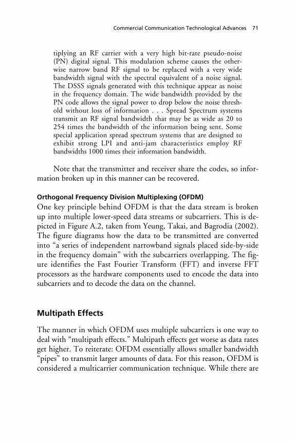
Commercial Communication Technological Advances 71
tiplying an RF carrier with a very high bit-rate pseudo-noise(PN) digital signal. This modulation scheme causes the other-wise narrow band RF signal to be replaced with a very widebandwidth signal with the spectral equivalent of a noise signal.The DSSS signals generated with this technique appear as noisein the frequency domain. The wide bandwidth provided by thePN code allows the signal power to drop below the noise thresh-old without loss of information . . . Spread Spectrum systemstransmit an RF signal bandwidth that may be as wide as 20 to254 times the bandwidth of the information being sent. Somespecial application spread spectrum systems that are designed toexhibit strong LPI and anti-jam characteristics employ RFbandwidths 1000 times their information bandwidth.
Note that the transmitter and receiver share the codes, so infor-mation broken up in this manner can be recovered.
Orthogonal Frequency Division Multiplexing (OFDM)
One key principle behind OFDM is that the data stream is brokenup into multiple lower-speed data streams or subcarriers. This is de-picted in Figure A.2, taken from Yeung, Takai, and Bagrodia (2002).The figure diagrams how the data to be transmitted are convertedinto “a series of independent narrowband signals placed side-by-sidein the frequency domain” with the subcarriers overlapping. The fig-ure identifies the Fast Fourier Transform (FFT) and inverse FFTprocessors as the hardware components used to encode the data intosubcarriers and to decode the data on the channel.
Multipath Effects
The manner in which OFDM uses multiple subcarriers is one way todeal with “multipath effects.” Multipath effects get worse as data ratesget higher. To reiterate: OFDM essentially allows smaller bandwidth“pipes” to transmit larger amounts of data. For this reason, OFDM isconsidered a multicarrier communication technique. While there are
72 Future Army Bandwidth Needs and Capabilities
Figure A.2OFDM Process
S
P
P
S
IFFT•
••
S
P
P
S
FFT•
••
•••
•••
IN OUTChannel
SymbolFrequency
FrequencyTx Rx
RAND MG156-A.2
SOURCE: Yeung, Takai, and Bagrodia (2002). Used with permission.
other techniques that use multiple carriers, OFDM can be made to beefficient by having these subcarriers overlap, as shown in Figure A.3,adapted from Chheda (2002).
This brings us to the other key principle behind OFDM: inter-ference between subcarriers is still avoided because the subcarriers aremade to be orthogonal to each other.
Comparison of Types of OFDM
OFDM is to an extent a concept with many commercial namesand/or variants. They are described in Table A.2. One of the newercommercial standards (802.11a) for higher-speed wireless networkingincorporates OFDM.

Commercial Communication Technological Advances 73
Figure A.3OFDM Efficiency via Subcarrier Overlap
Ch. 2 Ch. 3 Ch. 4 Ch. 5 Ch. 6 Ch. 7 Ch. 8 Ch. 9 Ch. 10Ch. 1
Saving of bandwidth
f
f
Conventional multicarrier technique
Orthogonal multicarrier modulation technique
RAND MG156-A.3
SOURCE: Chheda (2002).
OFDM: Past, Present, and Future
OFDM was proposed over thirty years ago, but implementation is-sues plagued its development until recently. The JTRS (Cluster 1)intends to be OFDM capable (JTRS 2C is DSSS based). Northrup-Grumman and Flarion, Inc. have proposed using an OFDM variant(called flash-OFDM) in a proposal for a national emergency commu-nication system, i.e., one that is mobile and can be trucked into anarea (McHugh, 2002). Flarion claims it can reach near the lofty goalsfor 4G data rates (1 Gbps indoors and 100 Mbps outdoors) with itsflash-OFDM approach. We have not seen data on this claim. Ray-theon is testing a scheme called adaptive-vector OFDM that is de-signed to incorporate the use of adaptive antenna arrays withOFDM-capable radios.

Tabl
e A
.2O
FDM
and
OFD
M-In
spir
ed T
ypes
Nam
eD
escr
ipti
onU
seN
otes
C-O
FDM
Code
OFD
MEu
rope
an d
igit
al r
adio
and
TVBS
T-O
FDM
Band
Seg
men
ted
Tran
smis
sion
OFD
MJa
pane
se d
igit
al T
VA
mor
e ad
vanc
ed v
ersi
on o
f C-
OFD
M t
hat
split
s up
sig
nal i
nto
fine
r su
bcha
nnel
s
W-O
FDM
Wid
eban
d O
FDM
Clai
med
by
Wi-L
an, I
nc. a
spr
opri
etar
y ve
rsio
nSo
me
argu
e th
at t
his
prop
riet
ary
sche
me
issi
mila
r to
C-O
FDM
Flas
h O
FDM
Als
o kn
own
as f
requ
ency
-hop
ping
OFD
MPo
tent
ial 4
G s
tand
ard
Flar
ion
clai
ms
data
rat
es 3
–4 t
imes
com
mer
cial
3G g
oals
;a N
orth
rup-
Gru
mm
an p
ropo
ses
ana
tion
al e
mer
genc
y co
mm
unic
atio
n sy
stem
usin
g th
is t
echn
olog
y.
V-O
FDM
Vec
tore
d O
FDM
for
fix
ed w
irel
ess
usin
g m
ulti
ple
ante
nnas
Corp
orat
e ow
ner:
Cla
rity
Wir
eles
s an
d CI
SCO
AV
-OFD
MRa
ythe
on p
ropo
ses
a hy
brid
cal
led
Ada
ptiv
e V
ecto
r O
FDM
; fre
quen
cy-
hopp
ing
hybr
id o
f FD
MA
/CD
MA
/TD
MA
Rayt
heon
con
cept
cla
imed
to
be a
hyb
rid
Mul
ti-C
arri
er-
CDM
ARo
ckw
ell C
ollin
s pr
opos
es a
hyb
rid
that
com
bine
s as
pect
s of
fre
quen
cyho
ppin
g, D
SSS,
and
the
mul
tica
rrie
rm
odul
atio
n in
here
nt w
ith
OFD
M t
opr
oduc
e a
mor
e A
L/LP
D s
chem
ere
lati
ve t
o “s
impl
e O
FDM
”
Part
of
FCS
com
mun
icat
ion
prog
ram
a M
cHug
h, J
osh,
“A
Hig
h W
irel
ess
Act
,” R
edhe
rrin
g, O
ctob
er 2
002.
74 Future Army Bandwidth Needs and Capabilities

Commercial Communication Technological Advances 75
BLAST
The Bell Labs Space and Time (BLAST) concept is a wireless com-munications technique that uses multi-element antennas at bothtransmitter and receiver. It has the potential for high spectral effi-ciency. It is not clear how such an arrangement is to be used in a mo-bile, tactical environment. The following description of BLAST wastaken from www1.bell-labs.com/project/blast/:
BLAST is an extraordinarily bandwidth-efficient approach towireless communication which takes advantage of the spatialdimension by transmitting and detecting a number of independ-ent co-channel data streams using multiple, essentially co-located, antennas. The central paradigm behind BLAST is theexploitation, rather than the mitigation, of multipath effects inorder to achieve very high spectral efficiencies (bits/sec/Hz), sig-nificantly higher than are possible when multipath is viewed asan adversary rather than an ally. Using our laboratory testbed,the BLAST team recently demonstrated what we believe to beunprecedented wireless spectral efficiencies, ranging from 20–40bps/Hz. By comparison, the efficiencies achieved using tradi-tional wireless modulation techniques range from around 1–5bps/Hz (mobile cellular) to around 10–12 bps/Hz (point-to-point fixed microwave systems). In the 30 kHz bandwidth util-ized by our research testbed, the raw spectral efficiencies realizedthus far in the lab correspond to payload data rates ranging fromroughly 0.5 Mb/s to 1 Mb/s. By contrast, the data rate achiev-able in this bandwidth using typical traditional methods is onlyabout 50 kbps.
Hybrids
All of the schemes above have advantages and disadvantages. Hybrid,multicarrier schemes9 (that utilize aspects of both CDMA and
____________9 Linnartz and Hara (1996) provide historical background on multicarrier modulation ingeneral as follows: “Multi-Carrier Modulation (MCM) is the principle of transmitting databy dividing the stream into several parallel bit streams, each of which has a much lower bitrate, and by using these substreams to modulate several carriers. The first systems using
76 Future Army Bandwidth Needs and Capabilities
OFDM) are likely to be the most advantageous ones. The term“Multicarrier CDMA” (MC-CDMA) is sometimes used to describeconcepts that combine conventional CDMA and OFDM. A fairlycomprehensive overview is provided by Hara and Prasad (1997).More research and development is probably needed for these con-cepts to get fielded.
Wi-Fi5
“Wi-Fi5” is a moniker used by some to refer to the IEEE 802.11astandard for wireless networks. The standard was proposed earlierthan Wi-Fi but is considered newer and is expected to achieve higherreal-world throughputs. It is intended to operate commercially at 5GHz, hence the name “Wi-Fi5.”
The related IEEE 802.11g standard is a mix of the two stan-dards described above. It is intended to be used at the 2.4 Ghz, aswith the “b” standard, and hence it will be compatible with the “b”standard. But it utilizes OFDM, as does the “a” standard. Its statedmaximum throughput will be at least as good as the “a” standard(10–11 Mbps). Thus, 802.11g is related to Wi-Fi and Wi-Fi5.
Estimates of real-world maximum throughput are roughly one-third to one-half the stated maximum. These estimates are docu-mented in Dornan (2002):
The theoretical maximum capacity of 802.11b is 11 MBps,which is often quoted by vendors and by groups such as WECA.It pushes wireless LANs through an important psychological
________________________________________________________MCM were military HF radio links in the late 1950s and early 1960s. Orthogonal Fre-quency Division Multiplexing (OFDM), a special form of MCM with densely spaced sub-carriers and overlapping spectra was patented in the U.S. in 1970. OFDM time-domainwaveforms are chosen such that mutual orthogonality is ensured even though subcarrierspectra may overlap. It appeared that such waveforms can be generated using a Fast FourierTransform at the transmitter and receiver. For a relatively long time, the practicality of theconcept appeared limited . . . today we appear to be on the verge of a breakthrough of MCMtechniques. Many of the implementation problems appear.”

Commercial Communication Technological Advances 77
barrier, matching the speed of the original Ethernet standard.However, the number is misleading. It refers to the total physicallayer capacity, much of which is used by the protocol itself, so itis not actually available for data. The maximum data rate of an802.11b network is really [at best] only about 6Mbps, and thatcan be achieved only under optimum condition—over a shortrange and with no interference. It quickly drops when packetcollisions or other errors occur. A 50% error rate will reduce thereal-throughput by about two thirds, to only 2Mbps.
Ultra-Wideband Technologies
The term “wideband” in the communication vernacular refers to asystem that uses a very wide range of frequencies. Ultra-widebandtechnology (UWB)10 involves radios that transmit across a very largepart of the spectrum, perhaps as much as 2 GHz. In this manner, it issimilar to the spread spectrum concept. An important detail for thecommercial application of UWB technology is its low power feature.The idea is that power is distributed across this very wide band suchthat the amount of power transmitted at any narrowband in the rangeis small and does not interfere with other radio transmissions. Thiscan allow this technology to be very spectral efficient. Critics of thecommercial application of this technology question the claim of lowinterference with other technologies. It is important to note thatcommercial applications focus on short-range communications, e.g.,10 meters or less.
A key advantage of the UWB concept is that simple pulses canbe used to transmit information (almost like Morse code). The com-bination of low power and less complexity could mean less cost.From this perspective, it is a competitor to Bluetooth technologies.Table A.3 contains a comparison of UWB to other concepts likeBluetooth and Wi-Fi. On February 14, 2002, the Federal Communi-
____________10 The concept has been around in military labs since the 1960s, mainly for radar systemsthat can look for objects buried below ground and behind walls (Jonietz, 2002).

78 Future Army Bandwidth Needs and Capabilities
cations Commission (FCC) authorized the commercial deploymentof UWB technology (see www.uwb.org).
Edwards (2001) explains how UWB could facilitate useful char-acteristics for the military communications with respect to covertness,jam-resistance, and resistance to multipath interference:
Ultra-wideband signals are spread across a larger band of fre-quencies than is required for normal narrowband transmissions.As a result, the average power or amplitude at any given fre-quency is virtually indistinguishable from background noise.This makes UWB signals more covert than narrowband signals.The wide operating bands of UWB systems make it difficult forjammers to distribute enough energy across all used frequencies(up to several GHz in some cases). Ultra-wideband signals alsodo not fade as much because they are time-modulated ratherthan amplitude modulated or frequency modulated. UWB radiopulses are short of such duration that the reflected versions ofthe signal do not cause destructive interference.
For the reasons described above, military communication appli-cations of this technology are being pursued by DARPA, which hasinitiated a new program called NETEX (Networking in Extreme En-vironments). The goal of the program is to demonstrate “ultra-wideband wireless networking capability that will enable us to com-municate with troops inside buildings, in built-up areas, and in otherchallenging environments” (Freebersyser, 2002, quotation attributedto Steven P. Griggs). DARPA intends to examine interference issueswith other types of radios.
Antenna Technologies
Directional antennas are being proposed to address key areas of im-provement needed in both the commercial and military sectors. Po-tential benefits include (1) better energy savings, (2) reduced interfer-ence, and (3) potential for improved throughput/capacity.Directional antennas can potentially provide improvements in these

Tabl
e A
.3Co
mpa
riso
ns o
f Se
lect
ed W
irel
ess
Com
mun
icat
ion
Tech
nolo
gies
Tech
nolo
gyRa
nge
(met
ers)
Dat
a Ra
te(M
bps)
Pow
er (m
illiw
atts
)Be
st S
uite
d fo
rCo
mm
erci
alA
vaila
bilit
y
Ult
ra-w
ideb
and
1010
020
0 (p
eak)
Shor
t-ra
nge,
hig
h-sp
eed
data
tra
nsfe
r (s
uch
asw
irel
ess
vide
o an
d au
dio)
Unc
lear
802.
11a
5030
1,00
0–2,
000
Hig
h-sp
eed
wir
eles
sco
mpu
ter
netw
orks
Now
802.
11b
100
650
0Co
mpu
ter
netw
orki
ng a
ndIn
tern
et a
cces
sN
ow
Blue
toot
h a10
130
Conn
ecti
ng c
ompu
ting
devi
ces
over
sho
rt d
ista
nces
for
text
tra
nsfe
r
Now
a Bl
ueto
oth
is a
sho
rt-r
ange
com
mun
icat
ion
conc
ept
suit
ed f
or w
irel
ess
conn
ecti
ons
of p
erip
hera
ls.
See
http
://w
ww
.blu
etoo
th.c
om.
Commercial Communication Technological Advances 79
80 Future Army Bandwidth Needs and Capabilities
areas, in addition to improved information assurance, i.e., low prob-ability of intercept (LPI), Anti-Jam (AJ), and low probability of de-tection (LPD).
Antenna Types
We can define two general categories of antennas: omnidirectionaland directional. Most commercial wireless local area networks rely onomnidirectional antennas, i.e., antennas that transmit in all direc-tions. Antennas designed to be pointed in a particular direction arecalled directional antennas.
Directional antennas can have a wide beamwidth, e.g., 120 de-grees, or a very narrow one, e.g., 30 degrees or less. The gain for di-rectional antennas can be relatively high, but the penalty is that theyhave to be mechanically or electronically pointed and arrayed to en-sure the ability to transmit/receive in selective directions.
Steered beam antennas are a type of directional antenna de-signed to change their beam pattern via software control, not physicalpositioning as with other types of directional antennas (see FigureA.4).
Transmission Energy Savings
Energy efficiency is important for nodes in military wireless networksfor a variety of reasons. One reason is to reduce onboard energy con-sumption on vehicles and man-packs that may rely on battery powerat least part of the time.11 Another is the reduction in interferencethat is engendered when a data packet is transmitted with the leastpower necessary to get to its intended receiver; in this manner, greater“spatial reuse” is facilitated (Vaidya, 2001). Spyropoulos and Raghav-
____________11 While onboard generators power most devices in Army combat vehicles, there are mostlikely instances in which it is desirable to have devices powered using batteries instead of anengine. In fact, future tactical vehicles are envisioned to be hybrids (i.e., battery power sup-ports propulsion power needs). Battery life then becomes an issue and, thus, the energy useof communication systems.

Commercial Communication Technological Advances 81
Figure A.4Steered Beam Antennas
Base station
Gain maximum is software controlled
RAND MG156-A.4
endra (2002) show a 45 percent improvement in energy cost savingswhen directional antennas are used instead of omnidirectional ones.
MAC and Routing Protocols for Directional Antennas
Research and development of MAC12 and routing protocols for di-rectional antennas is underway. Srisathapornphat and Shen (2003)document a few efforts. MAC protocols for some omnidirectionalantennas rely on broadcasts of request-to-send (RTS), clear-to-send(CTS), and acknowledgments of successful transmissions. Theseoverhead messages, which are not the data that need to be communi-cated, are broadcast to reserve access to the channel for the data. Ex-cessive overhead messages are wasteful but likely when the network is
____________12 MAC, or medium access control, refers to a methodology that determines how differentusers on a network share the same resources.

82 Future Army Bandwidth Needs and Capabilities
mobile and constantly changing. More research is needed on routingprotocols for directional antennas, as existing commercial systems (forwireless LANs) assume omnidirectional use. Selected routing proto-cols are surveyed in Appendix B.
Summary and Observation
This appendix surveyed advanced technologies relevant to the Army.Efforts highlighted include those being pursued in the commercialworld as well as those being developed in academia and governmentlaboratories. It is not clear where the commercial world will be in 10or more years;13 however, it is unlikely that it will develop somethingother than the current infrastructure-based 2G and 3G mobile phonesystem. The Army wants to adopt a communication architecture thatis mobile, ad hoc, and infrastructureless. Certainly, this is advanta-geous for the warfighter. But any acquisition advantage gained fromleveraging commercial technologies could fail to materialize.
____________13 Karen Miller, “Is Wi-Fi Just a Bubble,” Newsweek, September 29, 2003.
83
APPENDIX B
Routing Protocols for MANETs
Data routes in mobile ad hoc networks must be discovered. The ef-fect of mobile nodes on routing can be profound, since overhead as-sociated with route discovery can be significant compared with a fixednetwork. A number of routing algorithms have been developed todeal with the mobility aspect. Routing protocols for MANETs arebeing investigated heavily at the university research level (althoughthe vast majority of efforts are focused on protocols that assume om-nidirectional antennas). A large number of specific proposals forprotocols have been proposed in the Internet Engineering Task Force(IETF). A subset is described in Table B.1.
Investigation and comparison of various protocols is still an ac-tive area of research. There may exist a protocol yet to be developedthat is ideal for tactical MANETs. In particular, more investigation ofrouting protocols for directional antennas is needed.
Feeney (1999) suggests a taxonomy based on the following:
• Scheduling and route information maintenance: proactive andreactive types.
• State information: how informed each node is of the where-abouts of others.
• Structure: uniform or nonuniform (hierarchical) types of nodes.• Communication model (single or multiple channels).

84 Future Army Bandwidth Needs and Capabilities
Route Maintenance
Routing protocols fall into two general categories: proactive and re-active. There are conflicting results on which is better. Perhaps theanswer is neither, since the correct choice is situation dependent. Per-haps the answer is both, since they can be combined as a hybrid. Thepros and cons for these approaches are described in the followingparagraphs.
Proactive protocols require nodes to constantly assess source-destination routes and thus “suffer the disadvantage of additionalcontrol traffic that is needed to continually update stale routes” (Per-kins, 2001, p. 7). In general, the maintenance of proactive routinginformation can be costly in a wireless, ad hoc network. Sánchez,Evans, and Minden (1999) provide reasonable conjecture on thisparticular class of routing protocols: “In highly dynamic networks, itis futile to provide support for routing protocols that continuouslyevaluate routes within the network before they are actually requested(i.e., pro-active protocols). Pro-active techniques may cause tremen-dous traffic overheads on evaluating unnecessary routes. But routingprocedures that work on an as needed basis (i.e., reactive protocols)are more suitable to large, highly dynamic (MANETs).”
“On-demand” or reactive protocols develop routes when re-quested as opposed to proactive protocols1 that develop routes con-stantly. Reactive protocols are designed so routing information is ac-quired only when actually needed. However, the delay to find a routemay be intolerable. Reactive protocols may often use far less networkcapacity for maintaining the route tables at each node, but the latencyfor many applications will drastically increase (Perkins, 2001, pp.7–8). Some results suggest that this approach, used in commercialwireless networks, could also lead to significant overhead in mobile adhoc networks.
____________1 Note: Proactive protocols are also called “table-driven” protocols, since each node has tomaintain tables of information on how to route to any node in the network.

Routing Protocols for MANETs 85
Hybrid protocols that are sometimes reactive and sometimesproactive are highly advantageous. One example is the Zone RoutingProtocol (ZRP). According to Perkins (2001),
The Zone Routing Protocol takes a fresh yet time-tested ap-proach to protocol improvement by constructing a way to hy-bridize table-driven protocols (such as DSDV) with on-demandprotocols. ZRP uses zones that are similar to clusters, but insteadof hierarchical routing between clusters being used, special bor-der nodes are dynamically selected that connect adjacent zones.A zone radius parameter dynamically adjusts the size of the zone,in terms of the number of hops, as the network topologychanges. A different routing protocol can be used between zonesas compared to the one used within a zone. A proactive schemeis used inside the zone. Outside the zone routes are discoveredonly reactively. This approach is almost guaranteed to find ahappy medium between the two extremes that exhibits improvedproperties.
State Information
Some protocols require each node to maintain “large-scale topologicalinformation” such that neighboring nodes must advertise their con-nectivity to each other on a regular basis. This is referred to as a link-state approach, where “each node maintains a view of the networktopology with a cost for each link . . . each node periodically broad-casts the link costs of its outgoing links to all other nodes [via]flooding” (Perkins, 2001, p. 55). This can be expensive in terms ofoverhead and thus scales poorly. An alternative is having nodesmaintain/exchange more basic information with its immediate neigh-bors, i.e., distance and direction. A noteworthy approach is calledHazy-Sighted Link State (HSLS) routing. This is a hybrid schemeproposed by BBN that claims to be the proper balance between theneed to reduce overhead traffic while maintaining up-to-date routinginformation in a mobile network. Nodes send out updates (of routinginformation) to nearby nodes frequently and to farther out nodes lessoften. The idea is that if links change their state frequently, only the

86 Future Army Bandwidth Needs and Capabilities
most recent change is disseminated. Messages are routed using theaccurate local information, and as the messages become closer to theirdestination, the route information becomes more accurate.
Structure
Protocols may be hierarchical in that some nodes serve as backbonesor cluster-heads. Others treat all nodes as common. The latter are re-ferred to as flat networks. Hierarchical routing protocols are quitedifferent from routing protocols for purely flat networks.
The taxonomy utilized by Grossman and Portnoy (n.d.) is takenfrom IETF submissions and describes a number of the proposedrouting protocols with more detail than the taxonomy suggested byFeeney (1999).
• Loop freedom. Loops in routes can easily lead to packets’ float-ing around in a mobile network, hogging bandwidth and neverreaching the intended recipient.
• Multiple routes. Calculation of multiple routes from source torecipient.
• Unidirectional link support. Nodes’ ability to send messages toother nodes without a need for acknowledgement.
• Quality of service support. Whether or not guarantees on net-work performance can be facilitated.
• Periodic broadcasts. Reflects whether or not a protocol will berequired on broadcasts to all nodes.
• Sequenced data. Reflects whether the protocol required se-quenced data transmission.
Table B.1 lists a host of protocols. But the number of theseprotocols suitable for tactical MANETs is much smaller, since fewhave been tested for a tactical environment. Still, if directional anten-nas are planned, perhaps none of the above are usable. Clearly, re-search and development on routing protocols needs to continue.

Tabl
e B.
1Ro
utin
g Pr
otoc
ols
in D
evel
opm
ent
and/
or P
ropo
sed
DSD
VD
SRTO
RAZR
PCB
RPO
LSR
AO
DV
STA
RCE
DA
RRD
MA
R
Loop
-fre
eY
YN
YY
YY
NY
Y
Mul
tipl
e ro
utes
NY
YN
YY
NY
YY
Reac
tive
NY
YPa
rtY
NY
NPa
rtY
Uni
dire
ctio
nal l
ink
supp
ort
NN
NN
YN
NY
NY
QoS
sup
port
NN
NN
NN
NN
YN
Mul
tica
stN
NN
NN
NY
NN
N
Secu
rity
NN
NN
NN
NN
NN
Peri
odic
bro
adca
stY
NY
YY
YY
NY
N
Sequ
ence
d da
taN
NY
NN
NN
NN
N
Routing Protocols for MANETs 87


89
APPENDIX C
Who’s Working the Problem andEmerging Concepts
A large number of organizations are addressing FCS communicationsand sharing information. We describe some of them and the conceptsthey are exploring.
DARPA
FCS Communications Program
The FCS Communications Program is developing and testing hard-ware and software for mobile ad hoc networks, using directional an-tennas, with both terrestrial and airborne nodes. Sass and Freebersyser(2002) summarize the motivation for the program as follows.
In the frequency bands generally used for tactical mobile opera-tions (30–250MHz), there is generally not adequate bandwidthavailable to provide both increased capacity and AJ/LPD. As aresult, at the onset of this new DARPA program, it was con-cluded that a “high band” RF system, one operating above themicrowave band, would be required to supplement the lowerband RF systems traditionally used for tactical operations. Fur-thermore, since both their smaller platform dimensions and theirrequired mobility will restrict the size of the antenna structuresfor FCS platforms, the selection of the frequency of the highband system became a critical decision (trading antenna gain,propagation characteristics, technology maturity, and spectrumavailability). It was concluded that the selection of a frequencyband around 38 GHz would enable the simultaneous achieve-

90 Future Army Bandwidth Needs and Capabilities
ment of high data rates, LPD, AJ, and mobile operation throughthe use of highly directional antennas. A low band system wouldstill be necessary for interoperability with conventional groundforces and for operation in environments where a direct line ofsight may be unavailable due to terrain, foliage, or weather. Pro-viding the ability to transmit large amounts of data quickly whileavoiding jamming and detection will require significant ad-vancements in transmitters, receivers, and directional antennatechnology, as well as the use of mobile, ad hoc networkingtechniques with directional antennas.
Among the specific projects associated with the DARPA FCSprogram is an effort called Utilizing Directional Antennas for Ad hocNetworking (UDAAN). Quoting Sass and Freebersyser (2002), thisproject is
a DARPA-sponsored project under the FCS Communicationsprogram. BBN Technologies, Stow Research LLC, and TexasA&M University (TAMU) are developing a suite of protocolsfor utilizing directional antennas in ad hoc networks. A signifi-cant payoff from UDAAN will be increased effective capacity.Other payoffs include decreased packet latency, increased con-nectivity, greater multicast efficiency, and lower probability ofdetection/interference.
[The] contention is that the directionality inherent in high gainantennas can significantly improve the performance of ad hocnetworks by delivering higher effective capacity, lower latency,robust connectivity, and enhanced security.
Table C.1 highlights other DARPA FCS Communications Pro-gram funded initiatives. Several demonstrations have highlighted thesuccessful integration of a number of the technologies and conceptsoutlined in the table. The latest demonstration (Demo 3) was inAugust 2003 at the Orchard Training Area near Boise, Idaho. Thetests involved 20 ground-based vehicles (SUVs, one M-113A, oneHMMVV) and up to seven airborne nodes (two helicopters withsling nodes acting as airborne nodes and up to five UAVs). The

Tabl
e C.
1D
ARP
A F
CS C
omm
unic
atio
ns P
rogr
am F
unde
d In
itia
tive
s
Ven
dor
Topi
cD
escr
ipti
on
Rock
wel
l-Col
lins
(OFD
M) d
igit
al r
ecei
ver
arch
itec
ture
Dev
elop
a b
road
band
wav
efor
m t
hat
mee
ts t
he m
ulti
-rat
e FC
S co
mm
unic
atio
ns r
equi
re-
men
ts a
nd is
exp
anda
ble,
rec
onfi
gura
ble,
and
JTR
S-co
mpl
iant
tha
t ut
ilize
s O
FDM
.
BBN
Prot
ocol
s fo
r di
rect
iona
lan
tenn
asD
evel
op n
etw
ork
and
MA
C la
yer
prot
ocol
s fo
r th
e ex
ploi
tati
on o
f di
rect
iona
l ant
enna
sto
pro
vide
net
wor
k pe
rfor
man
ce im
prov
emen
ts in
cap
acit
y, la
tenc
y, r
obus
tnes
s, a
ndse
curi
ty.
Luce
ntTe
chno
logi
esBL
AST
: Bel
l Lab
s la
yere
dsp
ace
tim
e pr
oces
sing
Prov
ide
high
-dat
a-ra
te c
omm
unic
atio
ns u
sing
non
-line
-of-
sigh
t lin
ks in
hea
vy s
catt
erin
gen
viro
nmen
ts w
ith
mob
ile e
nd p
oint
s.
Rayt
heon
Band
wid
th-e
ffic
ient
netw
orki
ng w
ith
beam
form
ing
ante
nnas
Dev
elop
net
wor
k an
d m
edia
acc
ess
cont
rol (
MA
C) p
roto
cols
tha
t ex
ploi
t di
rect
iona
lan
tenn
as a
nd n
ode-
trac
king
dat
a an
d w
ill d
emon
stra
te a
d ho
c ne
twor
king
wit
hdi
rect
iona
l ant
enna
s in
sim
ulat
ion
and
prot
otyp
es; i
nves
tiga
te t
echn
ique
s fo
r ra
pid
beam
-for
min
g an
d de
nial
of
serv
ice
prev
enti
on.
Rock
wel
l-Col
lins
Hig
h-ba
nd, 3
8-gi
gahe
rtz,
beam
-for
mer
, act
ive-
arra
y an
tenn
a
Dev
elop
act
ive
arra
y an
tenn
a to
ena
ble
effi
cien
t be
am-s
teer
ing.
TRW
Mob
ile, w
ideb
and,
mill
imet
er-w
ave
radi
oD
evel
op 1
00 m
egab
its
per
seco
nd, p
eer-
to-p
eer
com
mun
icat
ion
radi
o w
ith
extr
eme
anti
-jam
, low
pro
babi
lity
of in
terc
ept
and
low
pro
babi
lity
of d
ecep
tion
.
Rayt
heon
Smar
t an
tenn
as a
ndso
ftw
are
radi
o fo
r FC
Slo
w b
ands
Dev
elop
and
dem
onst
rate
a s
mar
t, r
econ
figu
rabl
e an
tenn
a, a
JTR
S-co
mpl
iant
Ult
raCo
mm
sof
twar
e-de
fine
d ra
dio,
and
an
adap
tive
vec
tor
OFD
M h
igh-
data
-rat
e w
avef
orm
.
Scal
able
Net
wor
kTe
chno
logy
Inc.
Net
wor
k si
mul
atio
nA
hig
h-fi
delit
y, s
cala
ble,
net
wor
k si
mul
atio
n (e
.g.,
Glo
MoS
im) b
ased
on
the
Qua
lNet
tool
tha
t al
low
s de
taile
d m
odel
ing
of e
ach
laye
r of
the
com
mun
icat
ions
sta
ck a
ndde
mon
stra
tes
real
-tim
e si
mul
atio
n of
net
wor
ks w
ith
hund
reds
of
node
s.
BAE
Syst
ems
Low
ban
d ar
ch. s
yste
mfo
r di
rect
iona
l ant
enna
sD
evel
op a
n ul
tra-
wid
eban
d, c
o-lo
cate
d, m
eand
erlin
e an
tenn
a an
d as
soci
ated
sit
ing
(pla
tfor
m in
tegr
atio
n) t
echn
ique
s.
SOU
RCE:
DA
RPA
Fac
t Sh
eet,
“Fu
ture
Com
bat
Syst
ems
Com
mun
icat
ions
Pro
gram
,” M
ay 2
001.
See
als
o ht
tp://
ww
w.d
arpa
.mil/
body
/N
ewsI
tem
s/w
ordf
iles/
FCSC
omm
s501
.doc
.
Who’s Working the Problem and Emerging Concepts 91

92 Future Army Bandwidth Needs and Capabilities
ground vehicles moved on two roads and airborne nodes flew to pro-vide connectivity. Also deployed were Unattended Ground Sensors(UGS) to provide radar, SIGINT, and IR data that were fed into thecommunication network. The SUVs used directional antennas to giveredundant 20 degree antenna patterns. Robotic vehicles were em-ployed.
DARPA Next Generation (XG) Communications Program
The XG Communications Program is intended to demonstrate ena-bling technologies and system concepts to improve spectral utilizationof military radio frequency emitters by a factor of 20. These demon-strations will include demonstrating a low power/wideband spectrumsensor, time/frequency agile waveforms, and dynamic spectrum accessand control. Stated program goals: demonstrate an appliqué for leg-acy and future emitter systems for joint service utility; develop ena-bling technologies and system concepts to provide assured militarycommunications and sensors in support of worldwide, short-noticedeployments through the dynamic redistribution of allocated spec-trum; provide a common technical architecture that can meet theneeds of both military and civilian future (beyond 3G) mobile com-munications systems.
Quoting Price (2003):
Development of spectrum efficient technologies is a key compo-nent of any spectrum management solution. We are movingforward in developing what we consider to be the cutting edgeof spectrum use: DARPA’s neXt Generation spectrum program,known as XG. XG capitalizes on one of the factors identified bythe FCC Spectrum Task Force: access to spectrum is the keylimiting factor in using spectrum. In other words, spectrum maybe available but there is no way to access it. XG will allow thedynamic management of spectrum use by defining access basedon the dimensions of time, frequency and location. Currentspectrum users routinely differentiate on the basis of frequencyand location only. Enabling spectrum users to differentiate onthe basis of time will allow more users to access the spectrum.This will help change the antiquated zero-sum characteristics ofcurrent spectrum allocations. When XG and other technological

Who’s Working the Problem and Emerging Concepts 93
initiatives come to fruition, it will allow us move from a “userights model” of spectrum use, to a “dynamic access model.”This will be good for our military, other government users, andindustry.
Networking In Extreme Environments (NETEX)
The DARPA NETEX program is focused on communications forurban and special operations. The program “aims to create new wire-less networking technologies that address the challenges of rapidlycreating robust networks in complex and hostile environments, andof coordinating the assignment of available spectrum.” Specifically,ultra-wideband communication (see Appendix A) technologies andits networking capability are being investigated.
Tera Hertz Operational Reachback (THOR)
The DARPA THOR program is focused on providing “flexiblebroadband connectivity” to any point on the globe. This will involveoptical links from airborne platforms down to the ground as well asother air-to-air and ground-to-air links to enable communicationwith CONUS from the theatre and back.
Adaptive C4ISR Node
The DARPA adaptive C4ISR node (ACN) program is focused onproviding “a multi-mission RF system that provides seamless interop-erable communications, simultaneously with SIGINT, EW, and IOcapabilities.”
CECOM, ARL, and ARO
CECOM, ARL, and ARO are developing technologies for mobile adhoc networking. An example is the CERDEC Multifunctional On-the-Move Secure Adaptive Integrated Communications (MOSAIC)program.
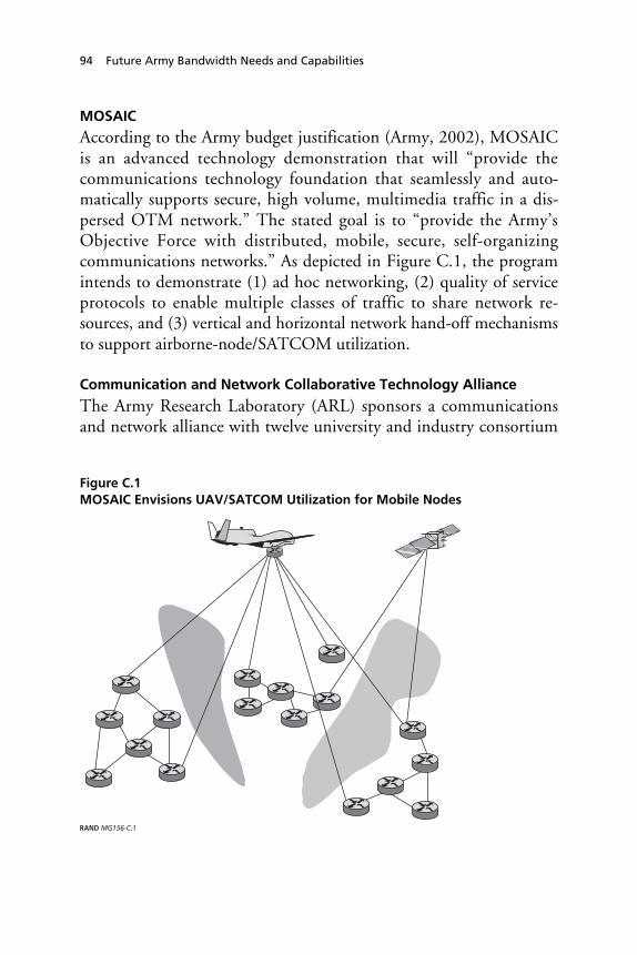
94 Future Army Bandwidth Needs and Capabilities
MOSAIC
According to the Army budget justification (Army, 2002), MOSAICis an advanced technology demonstration that will “provide thecommunications technology foundation that seamlessly and auto-matically supports secure, high volume, multimedia traffic in a dis-persed OTM network.” The stated goal is to “provide the Army’sObjective Force with distributed, mobile, secure, self-organizingcommunications networks.” As depicted in Figure C.1, the programintends to demonstrate (1) ad hoc networking, (2) quality of serviceprotocols to enable multiple classes of traffic to share network re-sources, and (3) vertical and horizontal network hand-off mechanismsto support airborne-node/SATCOM utilization.
Communication and Network Collaborative Technology Alliance
The Army Research Laboratory (ARL) sponsors a communicationsand network alliance with twelve university and industry consortium
Figure C.1MOSAIC Envisions UAV/SATCOM Utilization for Mobile Nodes
RAND MG156-C.1

Who’s Working the Problem and Emerging Concepts 95
members.1 The objective of the alliance is to study “technologies thatenable a fully-mobile, fully-communicating, agile, situation-aware,and survivable lightweight force with internetted C4ISR systems.”Specific research objectives and technologies include:
• survivable wireless mobile networks;• signal processing techniques to enable reliable low-power mul-
timedia communications among highly mobile nodes;• secure jam-resistant communications;• tactical information protection technologies that are real-time.
Others
CECOM/Mitre/TRAC is developing a communications networkingarchitecture also, approaching the problem from a top-down lookbased on postulated operational scenarios. AMSAA is currently usingNETWARS, a Joint Staff communications model, to assess FCSbandwidth needs. The Lead System Integrator (Boeing/SAIC) forFCS is developing its own system and operational architecture.ASD/C3I is addressing bandwidth issues at the tactical level (usingthe JTRS as discussed previously) and in its TCA (defined earlier),which is developing a concept for very high speed terrestrial and sat-ellite communications for global connectivity.
____________1 Telecordia (lead), BAE, Network Associates, Motorola, BBN, Georgia Tech, University ofMaryland, University of Delaware, Princeton, Johns Hopkins University, Morgan StateUniversity, CCNY, and Clark Atlanta University.


97
References
Anderson, C., “Transformational Communications,” MILSATCOM JointProgram Office, March 2002.
Army Communicator, “TSM Update,” Winter 2002, pp. 27–29.
Army Research Laboratory, “Short-range UHF Wireless Communicationsfor Unattended Battlefield Sensors: An Initial Site Evaluation to Char-acterize Propagation Across Forested Terrain,” SPIE, April 2002.
Army Spectrum Management Office, “Frequency & Band Selection Guid-ance for Objective Force (OF) Managers and Developers,” February 4,2002.
Banica, I., and C. Vladeanu, “Performance of Iterative Multistage Detectorsfor DS-CDMA Systems,” IEEE International Conference on Telecom-munications’ IEEE ICT2001’, Proceedings, Vol. 3, pp. 35–39, Bucur-esti, Iunie 4–7, 2001.
Blazevic, Ljubica, and Jean-Yves Le Boudec and Silvia Giordano, “A Loca-tion Based Routing Method for Irregular Mobile Ad Hoc Networks,” ac-cessed at citeseer.nj.nec.com/blazevic03location.html, 2003.
Bridges, Andrew, “Pentagon Turns to Commercial Satellites to Ease WarData Squeeze,” Associated Press, March 27, 2003.
Casper, Lawrence E., et al., “Knowledge-based Warfare: A Security Strategyfor the Next Century,” Joint Forces Quarterly 13, Autumn 1996, pp.81–89.
Cebrowski, Arthur K., and John J. Garstka, “Network-centric Warfare: ItsOrigin and Future,” Naval Institute Proceedings, January 1998.

98 Future Army Bandwidth Needs and Capabilities
Chheda, Shital Ratilal, “A Comparison Between Synchronous CDMA andOrthogonal Frequency Division Multiplexing (OFDM) for FixedBroadband Wireless Access,” Master’s Thesis, Department of Electricaland Computer Engineering, Virginia Tech, 2002.
CIS Division, NATO C3 Agency, “The NATO Post-2000 Narrow BandVoice Coder: Test and Selection of STANAG 4591, Technical Presenta-tion-001.
Congressional Budget Office, “The Army’s Bandwidth Bottleneck,” August2003.
Das, S., C. Perkins, and E. Royer, “Performance Comparison of Two On-demand Routing Protocols for Ad-hoc Networks,” INFOCOM, 2000.
Department of Energy, Atmospheric Radiation Measurement Program,“Vaisala Ceilometer (Model CT25K),” accessed at http://www.arm.gov/docs.
Dornan, Andy, The Essential Guide to Wireless Communications Applications,Prentice Hall, 2002.
Edwards, Sean, Freeing Mercury’s Wings: Improving Tactical Communicationin Cities, Santa Monica, CA: RAND Corporation, MR-1316-A, 2001.
ElBatt, T.A., S.V. Krishnamurthy, D. Connors, and S. Dao, “Power Man-agement for Throughput Enhancement in Wireless Ad-hoc Networks,”Proceedings of the International Conference on Communications (ICC2000), Volume 3, 2000, pp. 1506–1513.
“Encyclopedia of the Atmospheric Environment,” http://www.doc.mmu.ac.uk/aric/eae/Weather/Older/Thunderstorms.html, Atmosphere, Climateand Environment Information Program.
Feeney, Laura M., “A Taxonomy for Routing Protocols in Mobile Ad-HocNetworks,” SICS Technical Report T99/07, October 1999, accessed athttp://citeseer.nj.nec.com/feeney99taxonomy.html.
Foschini, G., and M. Gans, “On Limits of Wireless Communication in aFading Environment When Using Multiple Antennas,” submitted forpublication, 1998, accessed at citeseer.nj.nec.com/foschini98limit.html.
Freebersyser, James, “ATO Communications,” presented at the DARPA-Tech 2002 Conference, Anaheim, California, August 2, 2002. See alsohttp://www.darpa.mil/DARPATech2002/presentation.html.

References 99
Freebersyser, James, and Berry Leiner, A DoD Perspective on Mobile Ad-HocNetworks, Ad-Hoc Networking, Addison Wesley, 2001, ISBN 0-201-30976-9.
Graves, J.E., and S. Drenker, “Advancing Free Space Optical Commun-ications with Adaptive Optics,” http://www.aoptix.com/technology/white_papers/advancing_free_space.pdf.
Grobmeier, Col. John, PM TRACS, “Trends and Applications in Commer-cial Wireless Information Systems: Enabling FCS and U.S. Army OF,”presented at AFCEA, Monmouth Chapter, 2002, accessed at http://www.afcea-ftmonmouth.org/documents/part%203.pdf.
Grossglauser, M., and D. Tse, “Mobility Increases the Capacity of Ad-hocWireless Networks,” Conference Proceedings, IEEE, Volume 3, 2001,pp. 1360–1369.
Grossman, Daniel, and William Portnoy, “Ad-Hoc Routing for MobilePacket Networks: A Literature Review,” unpublished, accessed athttp://www.cs.washington.edu/homes/grossman/projects/561projects/adhoc/adhoc.ps.
Gupta, P., and P. Kumar, “Capacity of Wireless Networks,” Technical Re-port, University of Illinois, Urbana-Champaign, 1999.
Gupta, P., and P. Kumar, “The Capacity of Wireless Networks,” IEEETransactions on Information Theory, Vol. 46, No. 2, March 2000, avail-able at http://www-ece.rice.edu/~amlexa/sensornets/gupta_kumar00.pdf.
Gupta, P., and P. Kumar, “Internets in the Sky: The Capacity of ThreeDimensional Wireless Networks,” Communications in Information andSystems, Vol. 1, No. 1, 2001, pp. 39–49.
Gupta, P., R. Gray, and P. Kumar, “An Experimental Scaling Law for Ad-hoc Networks,” Technical Report, University of Illinois at Urbana, May,2001, accessed at citeseer.nj.nec.com/gupta01experimental.html.
Hara, S., and R. Prasad, “Overview of Multicarrier CDMA,” IEEE Com-munications Magazine, Vol. 35, No. 12, December 1997, pp. 126–133.
Haven, John, “Transformational Communication,” presented at MILSAT2003, February 2003, accessed at www.ags-inc.us/downloads/presentations/ColHaven_USAF.pdf.
Helmy, A., “Small Large-Scale Wireless Networks: Mobility-Assisted Re-source Directory,” U.S.C-TR and ACM-LANL-NCSTRL, July 2002.

100 Future Army Bandwidth Needs and Capabilities
Helmy, A., “Small Worlds in Wireless Networks,” IEEE CommunicationsLetters, Vol. 7, No. 12, October 2003.
Hillman, J., S. Jones, R. Nichols, and I. Wang, “Communications NetworkArchitectures for the Army Future Combat System and Objective Force,”Conference Proceedings, IEEE MILCOM, 2002.
Holland, Gavin, and Nitin H. Vaidya, “Analysis of {TCP} PerformanceOver Mobile Ad-Hoc Networks,” Mobile Computing and Networking,1999, pp. 219–230.
Horne, William D., “Adaptive Spectrum Access: Using the Full SpectrumSpace,” 31st Research Conference on Communication, Information andInternet Policy (TPRC), September 19, 2003.
Howard, William, “Coping with Change: Managing RF Spectrum to MeetDoD Needs,” Report of the Defense Science Board Task Force on DoDFrequency Spectrum Issues, November 2000.
IEEE Infocom, “On-demand Routing Protocols for Ad-hoc Networks,”Proceedings, March 2000.
Jain, Vivek, “Enhancing Network Throughput in Wireless Ad hoc Net-works using Smart Antennas,” 2003, accessed at http://www.ececs.uc.edu/~dlal/GM.ppt.
Jeganathan, D.M. and D.P. Ionov, “Multi-Gigabits-per-second OpticalWireless Communications,” http://www.freespaceoptic.com/WhitePapers/ Jeganathan%20%20(Optical%20Crossing).pdf.
Johns Hopkins University/Applied Physics Laboratory, Future CombatSystems Network-Centric Concepts and Operations, Phase I Report,May 2001.
Johns Hopkins University/Applied Physics Laboratory, Network-CentricArchitectures for the Army Future Combat Systems and Objective ForcePhase II: Architecture Performance Assessment, JWR-02-004, February2002.
Joint Forces Command, “Global Information Grid Capstone RequirementsDocument,” JROCM 134-01, August 2001.
Jonietz, Erika, “Ultra-wideband Squeezes In,” Technology Review, Septem-ber 2002, pp. 71–79.

References 101
Karn, P., “MACA: A New Channel Access Method for Packet Radio,” inARRL/CRRL Amateur Radio 9th Computer Networking Conference,pp. 134–140, ARRL, 1990.
Kim, I., and E. Korevarr, “Availability of Free Space Optics (FSO) andHybrid FSO/RF Systems,” accessed at www.freespaceoptic.com/WhitePapers/SPIE2001b.pdf, Optical Access Incorporated, 2001.
Kim, I., B. McArthur, and E. Korevaar, “Comparison of Laser BeamPropagation at 785 nm and 1550 nm in Fog and Haze for OpticalWireless Communications,” White Paper, Optical Access Incorporated,accessed at www.freespaceoptics.com, 2001.
Krane, Jim, “Military Wireless Networks Moving into Civilian Use,” Asso-ciated Press, December 8, 2002.
Li, J., C. Blake, D. De Couto, H. Lee, and R. Morris, “Capacity of Ad-hocWireless Networks,” Mobile Computing and Networking, 2001, pp.61–69.
Linnartz, Jean-Paul, and Shinsuke Hara, “Special Issue on Multi-CarrierModulation,” Wireless Personal Communication, No. 1–2, 1996, http://www.eecs.berkeley.edu/Research/Projects/ofdm/wireless/mcm.html.
Martin, Gary, “Open Architecture Solutions for Tactical Wireless Commu-nication, Software Defines Radio Forum General Meeting, February 7,2001, accessible at http://www.mmitsforum.org/ MTGS/mtg_22_feb01.
McHugh, Josh, “A High Wireless Act,” Redherring, October 2002.
MILCOM, Communications for Network-Centric Operations, Creatingthe Information Force, Proceedings of MILCOM 2001, October 2001.
Milgram, S., “The Small World Problem,” Psychology Today, Vol. 1, No.61, 1967.
Moseley, Michael, “Operation Iraqi Freedom—By The Numbers,”U.S.CENTAF, Assessment and Analysis Division, April 20, 2003 (un-classified).
Nasipuri, A., S. Ye, J. You, and R. Hiromotoe, “A MAC Protocol for Mo-bile Ad-hoc Networks Using Directional Antennas,” IEEE, 2000.
National Telecommunications and Information Administration (NTIA),“An Assessment of the Viability of Accommodating Advanced MobileWireless (3G) Systems in the 1710–1770 MHz and 2110–2170 MHz
102 Future Army Bandwidth Needs and Capabilities
Bands,” July 22, 2002, accessed on September 6, 2002 at http://www.ntia.doc.gov/ntiahome/threeg/va7222002/3Gva072202web.htm
Ohira, T., “Emerging Adaptive Antenna Techniques for Wireless Ad-hocNetworks,” The 2001 IEEE International Symposium on Circuits and Sys-tems, Vol. 4, May 6–9, 2001, pp. 858–861.
OSD/PA&E, “Communications and Digitization—The CommunicationsBottleneck,” briefing, September 20, 2000.
Patch, Kimberly, “Shortcuts Lighten Wireless Load,” TRN News, August21–28, 2002, accessed at http://trnmag.com/Stories/2002/082102/Shortcuts_lighten_wireless_load_082102.html on September 1, 2002.
Perkins, Charles (ed.), Ad Hoc Networking, Boston: Addison-Wesley, 2001.
Plummer, Ann, “Enduring Freedom Used Seven Times the Bandwidth Re-quired in 1991 War,” Inside the Pentagon, January 16, 2003.
Price, Stephen, Prepared Testimony to the Commercial Spectrum En-hancement Act Subcommittee on Telecommunications and the Internet,U.S. House of Representatives, March 25, 2003, accessed at energycom-merce.house.gov/108/Hearings/03252003hearing843/Price1390.htm.
Rafol, S.D.B., and K. Wilson, “Adaptive Multiplexing for Free-Space Opti-cal Communication: Wavelength- and Code-division MultiplexingWould Be Utilized for Security and Improved Performance,” NASA JetPropulsion Laboratory, accessed at http://www.nasatech.com/TSP/PDFTSP/NPO20890.pdf.
Ramanathan, Ram, “Part 5: System Design, Prototype, and Experiences,”Tutorial Session, Mobihoc’03, 2003, accessed at http://www.ir.bbn.com/~ramanath/tut-part5.pdf.
Reed, David, “How Wireless Networks Scale: The Illusion of SpectrumScarcity,” presented at FCC Technical Advisory Council, Washington,D.C., April 26, 2002.
Romero, Simon, “Military Now Often Enlists Commercial Technology,”The New York Times, March 10, 2003.
Sanchez, Fabio, and Geraldo Chowell-Puente, “Disease Dynamics On aSmall-World and Other Network,” Technical Report, Cornell Univer-sity, August 27, 2001.

References 103
Sanchez, M., “Multiple Access Protocols with Smart Antennas in MultihopAd Hoc Rural-Area Networks” Dissertation, June 2002, accessed athttp://www.s3.kth.se/radio/Publication/Pub2002/Sanchez_Lict2002.pdf.
Sanchez, M., T. Giles, and J. Zander, “CSMA/CA With Beam FormingAntennas in Multi-hop Packet Radio,” Proc. Swedish Workshop onWireless Ad-hoc Networks, March 5–6, 2001.
Sánchez, Ricardo, Joseph Evans, and Gary Minden, “Networking on theBattlefield: Challenges in Highly Dynamic Multi-hop Wireless Net-works,” IEEE MILCOM, 1999.
Sass, Paul, and Jim Freebersyser, “FCS Communications Technology forthe Objective Force,” Technical Report, Mitre Corporation, 2002.
Shaaber, Mark, Scott Hedberg, and Troy Wesson, “V Corps: C4ISR Inte-gration AAR,” May 2003.
Shen, Chien-Chung, Chavalit Srisathapornphat, Chaiporn Jaikaeo, “SensorInformation Networking Architecture and Applications,” IEEE PersonalCommunication Magazine, August 2001.
Sirak, Michael, “U.S. Air Force Targets UAV Bandwidth Problem,” Jane’sDefense Weekly, July 31, 2002.
Spyropoulos, A., and C. Raghavendra, “Energy Efficient Communicationsin Ad Hoc Networks Using Directional Antennas,” in Proceedings, IEEEInfocom, 2002.
SRI International, “SRI International and ITT Demonstrate New Tech-nologies that Put Battlefield Information in the Hands of Individual Sol-diers,” News Release, April 4, 2001, accessed at www.sri.com/news/releases/04-04-01.html.
Srisathapornphat, Chavalit, and Chien-Chung Shen, “Energy ConsumptionBehavior and Performance of Directional Virtual Carrier SensingSchemes,” IEEE Wireless Communications and Networking Conference(WCNC), New Orleans, LA: March 16–20, 2003. See also http://alfalfa.cis.udel.edu:8080/refs/papers/srisatha03energy.pdf.
Stein, Fred P., “Observations on the Emergence of Network Centric War-fare,” Proceedings of the 1998 Command and Control Research andTechnology Symposium. Naval Postgraduate School, Monterey, CA, 29June–1 July 1998, Washington, D.C.: National Defense University,1998.

104 Future Army Bandwidth Needs and Capabilities
Toomey, Christopher, “C4ISR in the Stryker Brigade Combat Teams,”Military Review, May–June, 2003, pp. 42–46.
Toumpis, S., and A. Goldsmith, “Ad-hoc Network Capacity,” Signals, Sys-tems and Computers, Conference Record of the Thirty-Fourth AsilomarConference on, Vol. 2, 2000, pp. 1265–1269.
U.S. Army, “Army RDT&E Budget Item Justification (R-2 Exhibit),”http://www.dtic.mil.descriptivesum/Y2003/Army/0603008A.pdf, 2002.
U.S. Army, Tactics, Techniques and Procedures for the Enhanced Position Lo-cation Reporting System, FM-24-41, July 1999.
U.S. Army CECOM, “Joint Common Database DII COE Conference,”briefing presented April 1999.
U.S. Army CECOM, “Tactical High Speed Data Network,” briefing pre-sented March 2002.
U.S. Army CECOM RDEC, Space and Terrestrial Communications Di-rectorate, “Science and Technology Overview, Communications Band-width,” briefing presented March 2002.
U.S. Army CECOM RDEC, “Multifunctional On-the-Move Secure Adap-tive Integrated Communications (MOSAIC) ATD,” briefing presentedMarch 2002.
U.S. Army CECOM RDEC, “Brigade Subscriber Node, Networking theInterim Brigade Combat Team,” briefing presented March 2002.
U.S. Army CECOM MILSATCOM Project Manager, “ArmyMILSATCOM Terminal Requirements,” briefing presented March2002.
U.S. Army CECOM OPM TRCS, “Future Bandwidth Requirements forTactical Radio Products,” briefing presented March 2002.
U.S. Army CECOM and The Mitre Corporation, “FCS CommunicationsNetworking Architecture,” briefing presented March 2002.
U.S. Army TRADOC, Combined Arms Center Army Battle CommandOperational Architecture (CACACOA) Version 3.1, ACOA-AM-3.1-Dv1, June 29, 2001.
U.S. Army Signal Center, Brigade Combat Team 1, Version 3.0, March 28,2001.

References 105
U.S. Army TRADOC, Joint Tactical Radio System Operational RequirementsDocument, November 2001.
U.S. Army TRADOC, Migration Plan, Trojan Spirit II to Warfighter Infor-mation Network, Volume II, August 2001.
U.S. Army TRADOC, WIN-T and JTRS, CSA Information Briefing, Feb-ruary 2002.
U.S Department of Commerce (DOC), “Bush Administration ForgesLandmark Plan for Spectrum Allocation,” Press Release, July 2002, ac-cessed on September 6, 2002 at http://www.ntia.doc.gov/ntiahome/press/2002/va7232002.htm.
Vaidya, N., “Mobile Ad-Hoc Networks: Routing, MAC and Transport Is-sues,” 2001, accessed at http://www.crhc.uiuc.edu/~nhv on September 2,2002.
Watts, D. J., Small Worlds: The Dynamics of Networks Between Order andRandomness, Princeton University Press, 1999.
Watts, D., and S. Strogatz, “Collective Dynamics of ‘Small-World’ Net-works,” Nature, Vol. 393, No. 440, 1998.
Wilson, Jeffrey W., “The Importance of Mobility Model Assumptions onRoute Discovery, Data Delivery, and Route Maintenance Protocols forAd-Hoc Mobile Networks,” Technical Report, Virginia Polytechnic In-stitute and State University, December 2001, accessed at http://wilsonjw.tripod.com/wilsonjw011212.pdf.
Yeung, G., M. Takai, and R. Bagrodia, “Integration of an OFDM RadioModel into Qualnet,” presented at the ONR Summer 2002 Meeting,http://www.cs.ucla.edu/~gavin.
Yi, Su, Yong Pei, and Shivkumar Kalyanaraman, “On the Capacity Im-provement of Ad-hoc Wireless Networks Using Directional Antennas,”Proceedings of the Fourth ACM International Conference on MobileAd-Hoc Networking and Computing, 2003, pp. 108–116.