for more than 50 years, garlock helicoflex has - rikenag.riken.jp/ddr/catalog/helicoflex.pdf ·...
TRANSCRIPT

For more than 50 years, Garlock Helicoflex has engineered performance metal seals and seal-ing systems. We have consistently been at the forefront of metal sealing in numerous industries. From seals designed for the first generation of Nuclear Power Plants to present day cryogenic space applications, our approach has been consis-tent...engineer the best seal for the most demand-ing applications. This design expertise allows us to partner with our customers to provide industry leading engineering and testing support.
Our sales and engineering staff are focused on individual markets, not territories, to maintain ex-pertise in a specific field. If you have questions or would like to discuss a specific application, please contact us at our world headquarters in Columbia,
South Carolina (USA).
2 | Introduction Rev 0 Contact Applications Engineering at: 800-233-1722
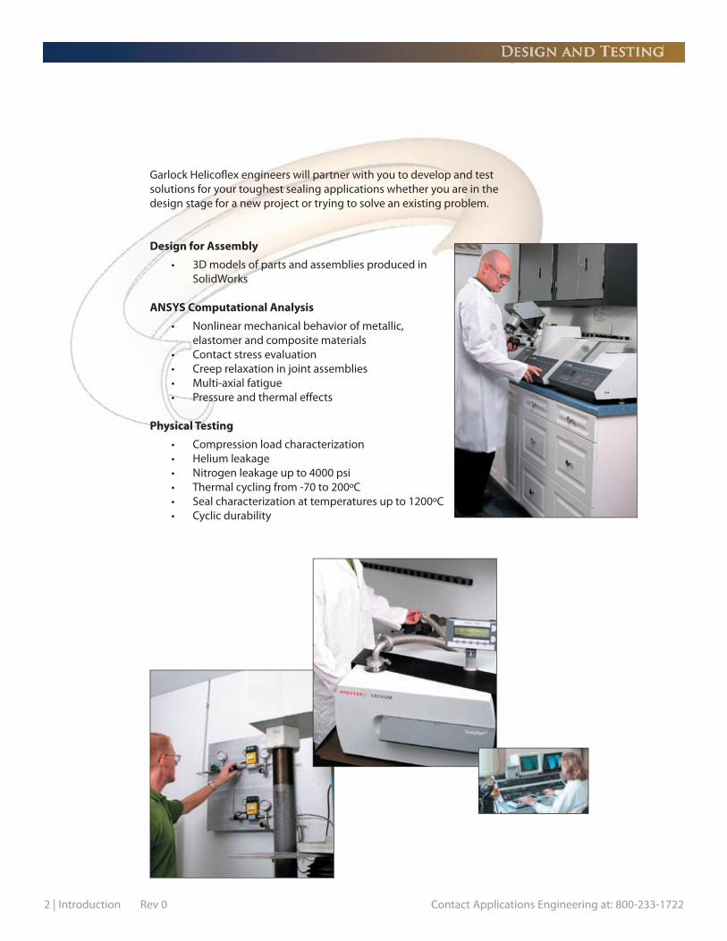
Garlock Helicofl ex engineers will partner with you to develop and test solutions for your toughest sealing applications whether you are in the design stage for a new project or trying to solve an existing problem.
Design for Assembly
• 3D models of parts and assemblies produced in SolidWorks
ANSYS Computational Analysis
• Nonlinear mechanical behavior of metallic, elastomer and composite materials • Contact stress evaluation • Creep relaxation in joint assemblies • Multi-axial fatigue • Pressure and thermal eff ects
Physical Testing
• Compression load characterization • Helium leakage • Nitrogen leakage up to 4000 psi • Thermal cycling from -70 to 200ºC • Seal characterization at temperatures up to 1200ºC • Cyclic durability
Design and Testing

Contact Applications Engineering at: 800-233-1722 Rev 0 Introduction | 3
Garlock Helicofl ex is committed to providing the highest quality metal seals and sealing systems. We provide seals for use in some of the most critical and demanding applica-tions, including aerospace, nuclear power generation and automotive. Our quality system is monitored by our customers as well as third party auditing fi rms. We are certifi ed to International Standards ISO9000:2000 and AS9100B. Our quality program also meets the requirements of 10CFR50 Appendix B. We welcome customer audits as well as source inspections.
Our staff includes multiple Certifi ed Quality Engineers and Certifi ed Quality Auditors, and we are committed to our Quality Policy of Total Customer Value throughout our supply chain.
We perform Liquid Penetrant Inspection and Radiographic Examination to Section V of the ASME Boiler & Pressure Vessel Code.
Quality Assurance

4 | Introduction Rev 0 Contact Applications Engineering at: 800-233-1722
EUROPE
Garlock (Great Britain) Limited
Premier WayLowfi elds Business ParkElland, West Yorkshire HX5 9HFUnited Kingdom
Email: [email protected]: [email protected] Site: www.garlock.eu.com
Tel: 44 (14 2) 231.3600Fax: 44 (14 2) 231.3601
Garlock France SAS
90, rue de la Roche du GeaiF-42029 Saint Etienne Cedex 1, France
Email: [email protected] Site: www.garlock.eu.com
Tel: 33 (4) 7743.5100 Fax: 33 (4) 7743.5151
Garlock GmbH Sealing Technologies Division
Falkenweg 141468 Neuss, Germany
Email: [email protected] Site: www.garlock.eu.com
Tel: (49) 2131.3490Fax: (49) 2131.349.222
ASIA
Garlock Valqua
Shinjyuku-DaiichiseimeiBuilding 15 F, 7-1Nishishinjyuku 2-ChomeShinjyuku-ku Tokyo, Japan
Phone: 03-3344-5835Fax: 03-3344-5065
Contact Information
USA
Garlock Helicofl ex
2770 The Boulevard Columbia, SC 29209 USA
Email: sales@helicofl ex.com Web Site: www.helicofl ex.com
Tel: (803) 783.1880 Toll Free: 800-233-1722 Fax: (803) 783.4279
Nuclear Power PlantEmergency Response Contact
(803) 695-3553 (U.S.A.)

Seal Selection Guide by Performance
Helicofl ex® Delta® O-Flex™ C-Flex™
ApplicationInformation
SEAL TYPE
E-Flex™U-Flex™*
Ultra HighVacuum
Low Pressure
High Pressure
CryogenicTemperature
High Temperature
Spring Back
Shaped Seals
Axial Sealing
QDS Compatible
Seating Load
Leak RateApproximation
High ModerateHigh
Moderate
Moderate
LowLow
High
Moderate
HeliumUltra-
HeliumHelium
Bubble
Helium
Bubble
Low
BubbleHelium
Application Legend
Recommended - Excellent
Recommended - Good
Optional - Special Design
Not Recommended
Leak Legend
Ultra-Helium
Helium
Bubble
Low Bubble
Approximate Leak Ratesper meter of circumference Actual leak rate in service will depend on the following:
≤ 1 x 10-11 std.cc/sec He
≤ 1 x 10⁻⁹ std.cc/sec He
≤ 1 x 10⁻⁴ std.cc/sec He
≤ 25 cc/sec @ 50 psig Nitrogenper inch of diameter
Seal Load: Wall Thickness or Spring Load
Surface Finish: Seal and Cavity
Surface Treatment: Coating/Plating/Jacket Material
MachinedSeal*
Contact Applications Engineering at: 800-233-1722 Rev 2 Seal Selection Guide | 1
* See Custom Seals Section

Fuel Nozzles E-FLEXTM C-FLEXTM HELICOFLEX® Bleed Air E-FLEXTM C-FLEXTM O-FLEXTM Casing/Cowling E-FLEXTM Fuel Delivery MS O-Rings Boss Seal* V-Band Coupling E-FLEXTM C-FLEXTM HELICOFLEX® QDS®Compressor Discharge E-FLEXTM HELICOFLEX® C-FLEXTM Electronic Enclosures DELTA® HELICOFLEX® C-FLEXTM Gear Box HELICOFLEX® C-FLEXTM Rocket Engine & Turbo Pumps E-FLEXTM HELICOFLEX® C-FLEXTM MS Standards MS Orings C-FLEXTM MS 33649/AS 5202/ Boss Seal* C-FLEXTM
AS 4395 Fluid Ports
Aerospace
Weapons HELICOFLEX® C-FLEXTM O-FLEXTM
Missiles DELTA® HELICOFLEX® C-FLEXTM
Electronic Enclosures DELTA® HELICOFLEX® C-FLEXTM
MS 33649/AS 5202/ Boss Seal* C-FLEXTM
AS 4395 Fluid Ports Military Standards MS O-Rings C-FLEXTM Exhaust Systems HELICOFLEX® C-FLEXTM O-FLEXTM
Fuel Delivery HELICOFLEX® C-FLEXTM DELTA®Satellite Systems DELTA® HELICOFLEX® C-FLEXTM
Laser & RF Guidance Systems DELTA® HELICOFLEX®
Defense
Drill Heads HELICOFLEX® O-FLEXTM Valves HELICOFLEX® C-FLEXTM O-FLEXTM
Steam Chucks HELICOFLEX® Piping & Flanges HELICOFLEX® QDS® Electronic Enclosures DELTA® HELICOFLEX® C-FLEXTM
& PackagingsFlow Control HELICOFLEX® C-FLEXTM Pressure Gauges HELICOFLEX® C-FLEXTM Well Head Plug HELICOFLEX® C-FLEXTM
Oil & Gas - Downhole Equipment & Upstream Production
Heat Exchangers HELICOFLEX® O-FLEXTM Bonnet Seals HELICOFLEX® O-FLEXTM C-FLEXTM
Valve Seats HELICOFLEX® Stem Seals HELICOFLEX® C-FLEXTM Piping & Flanges HELICOFLEX® QDS® Process Sampling HELICOFLEX® C-FLEXTM O-FLEXTM
Specialty Compressors HELICOFLEX® C-FLEXTM O-FLEXTM
Oil & Gas - Refi ning & Downstream Factories
End Point Windows DELTA® Chamber Lids DELTA® Exhaust Lines QDS® DELTA® Injectors DELTA® Machined Seal*Bulkhead Connections DELTA®
Gas Delivery System Machined Seal* Mass Flow Controllers Machined Seal* DELTA®Valve Manifold Box (VMB) Machined Seal* Gas Isolation Box (GIB) Machined Seal* Turbo Pumps DELTA®
Semiconductor - Sub Systems
Semiconductor - Front End Processing
Seal Selection Guide by Market/Application
Application Section
* See Custom Seals Section
2 | Seal Selection Guide Rev 2 Contact Applications Engineering at: 800-233-1722

Ampoules DELTA®Gas Canisters DELTA®Chemical Canisters DELTA®
Semiconductor - Materials
RF Waveguides DELTA® Particle Accelerators DELTA® Fusion Reactors DELTA® Klystron Tubes DELTA®
National Laboratories
Pressure Vessel HELICOFLEX® O-FLEXTM Spent Fuel Casks HELICOFLEX® O-FLEXTM Waste Heat HELICOFLEX® O-FLEXTM Primary Loop HELICOFLEX® O-FLEXTM QDS®Control Valves HELICOFLEX® O-FLEXTM CRD / BWR O-FLEXTM Pressurizer HELICOFLEX® O-FLEXTM
Nuclear
Fuel Nozzles HELICOFLEX® C-FLEXTM E-FLEXTM Cooling Steam HELICOFLEX® C-FLEXTM E-FLEXTM
Casing E-FLEXTM HELICOFLEX® Fuel Delivery MS Orings* Boss Seal*V-Band Coupling U-FLEXTM* C-FLEXTM E-FLEXTM QDS®Compressor Discharge HELICOFLEX® C-FLEXTM E-FLEXTM Electronic Enclosures DELTA® HELICOFLEX® C-FLEXTM
Gear Box HELICOFLEX® C-FLEXTM
Rocket Engine & Turbo Pumps E-FLEXTM HELICOFLEX® C-FLEXTM
MS Standards MS Orings C-FLEXTM
Fuel Nozzle Locking Rings & Plates Contact Applications Engineering
Power Gen: Land Based Turbines
Head Gasket Replacement HELICOFLEX® O-FLEXTM Cooper Ring Replacement HELICOFLEX® O-FLEXTM Head to Header Interface U-FLEXTM* C-FLEXTM HELICOFLEX® O-FLEXTM Exhaust Systems U-FLEXTM* C-FLEXTM HELICOFLEX®Turbochargers Internal U-FLEXTM* C-FLEXTM HELICOFLEX® O-FLEXTM
and External InterfacesStack-up Tubular Springs O-FLEXTM C-FLEXTM U-FLEXTM* E-FLEXTM
High Pressure Fuel Injection HELICOFLEX® O-FLEXTM C-FLEXTM Fuel Cell High Pressure Feed HELICOFLEX® O-FLEXTM C-FLEXTM Fuel Cell Exhaust Path C-FLEXTM U-FLEXTM* Catalytic Converter Connections U-FLEXTM* C-FLEXTM
High Performance Automotive
Hot Runner Components HELICOFLEX® O-FLEXTM C-FLEXTM
Manifold Plates HELICOFLEX® O-FLEXTM C-FLEXTM
Extruder Plates HELICOFLEX® O-FLEXTM C-FLEXTM
Filter Packs HELICOFLEX® O-FLEXTM C-FLEXTM
Spinnerrettes HELICOFLEX® O-FLEXTM C-FLEXTM
Screen Changers HELICOFLEX® O-FLEXTM C-FLEXTM
Instrumentation Ports HELICOFLEX® O-FLEXTM C-FLEXTM
Plastic Injection Molding
Seal Selection Guide by Market/Application
Application Section
* See Custom Seals Section
Contact Applications Engineering at: 800-233-1722 Rev 2 Seal Selection Guide | 3


Contact Applications Engineering at: 800-233-1722 Rev 2 Helicoflex® Spring Energized Seals | 1
The sealing principle of the Helicoflex® family of seals is based upon the plastic deformation of a jacket of greater ductility than the flange materials. This occurs between the sealing face of a flange and an elastic core composed of a close-wound helical spring. The spring is selected to have a specific compression resistance. During compression, the resulting specific pressure forces the jacket to yield and fill the flange imperfections while ensuring positive contact with the flange sealing faces. Each coil of the helical spring acts independently and allows the seal to conform to surface irregularities on the flange surface. This combination of elasticity and plasticity makes the Helicoflex seal the best overall performing seal in the industry.
Sealing Concept
Compression
Compression Specific Pressure
Elasticity Plasticity
These two functions ensure and maintain specific pressure in service.

2 | Helicoflex® Spring Energized Seals Rev 2 Contact Applications Engineering at: 800-233-1722
Configurations
Typical Configurations
HN200Groove Assembly
HN203Tongue & Groove
HN208Raised face fl ange - ANSI B16.5
HN2403 Face Compression
HND229Valve Seat
HNDE290Leak check - Insert Gas Purge
Classification of Seal Type
HN 2 0 8Cross Section
Type# Jackets/
LiningJacket
OrientationSection
Orientation
0 1 2 3 4 5 6 7 8 9
0 1 2 3 4 5 6 7 8 9
Configuration Guide CrossSectionType
HN single sectionHNR ground spring for precise load control (Beta Spring)HNV low load (Delta Seal)HND tandem Helicofl ex sealsHNDE tandem Helicofl ex and elastomer seals note: “L” indicates internal limiter (ex: HLDE)
Jacket/ 1 = jacket only 2 = jacket with inner liningLining
JacketOrientation
SectionOrientation — — —
Example

Contact Applications Engineering at: 800-233-1722 Rev 2 Helicoflex® Spring Energized Seals | 3
Performance Data
Characteristic Curve The resilient characteristic of the Helicofl ex® seal ensures useful elastic recovery during service. This elastic recovery permits the Helicofl ex® seal to accommodate minor distortions in the fl ange assembly due to temperature and pressure cycling. For most sealing applications the Y
0 value will occur early in
the compression curve and the Y1 value will occur near the end of the decompression curve.
The compression and decompression cycle of the Helicofl ex® seal is characterized by the gradual fl at-tening of the compression curve. The decompression curve, which is distinct from the compression curve, is the result of a hysteresis eff ect and permanent deformation of the spring and jacket.
Defi nition of Terms
Y0 = load on the compression curve above
which leak rate is at required level
Y2 = load required to reach optimum
compression e2
Y1 = load on the decompression curve
below which leak rate exceeds required level
e2 = optimum compression
ec = compression limit beyond which
there is risk of damaging the spring
���
����
�����
�
��
��
��
�� �� �� ����������������������� �����������������������
�������������������
��������������������
���
����
����
The Intrinsic Power of the Seal The intrinsic power of the Helicofl ex seal refl ects its ability to maintain and hold system pressure for a given temperature at Y
2 and e
2. This value is expressed as a specifi c pressure and is noted by the sym-
bols Pu (room temperature) and Pu (at operating temperature). The infl uence of temperature on Pu is shown in the graph below. The table on page 4 gives the values of Pu at 68°F (20°C), Pu at a given temperature and the maximum temperature where Pu = 0.
��
��
������������
����������������
���
O
OO

4 | Helicoflex® Spring Energized Seals Rev 2 Contact Applications Engineering at: 800-233-1722
Performance Data
Max Cross e
2 e
C Y
2 Y
1 Pu68°F Pu 392°F Y
2 Y
1 Pu68°F Pu 392°F Temp
Section lbs/inch lbs/inch PSI PSI lbs/inch lbs/inch PSI PSI °F
0.063 0.024 0.028 857 114 7250 N/A 514 114 5075 N/A 3020.075 0.028 0.033 914 114 7540 N/A 571 114 5800 N/A 3020.087 0.028 0.035 942 114 7685 N/A 600 114 5800 N/A 3560.098 0.028 0.035 999 114 7975 725 657 114 6090 725 4280.118 0.031 0.039 1056 143 7975 1450 742 114 6525 1450 4820.138 0.031 0.039 1085 143 7975 2030 799 114 6815 2030 4820.157 0.035 0.043 1142 143 8700 2465 857 114 7250 2465 5360.177 0.035 0.047 1199 143 8700 2900 914 114 7540 2900 5360.197 0.035 0.055 1256 171 9135 3190 971 143 7975 3190 5720.217 0.035 0.063 1313 171 9425 3480 1028 143 8265 3480 6080.236 0.039 0.071 1399 200 9715 3625 1113 171 8700 3625 6440.276 0.039 0.087 1542 228 10150 4060 1171 200 9425 4060 6440.315 0.039 0.102 1656 286 10440 4640 1285 228 9860 4495 680
Pu 482°F Pu 482°F
0.063 0.020 0.024 1142 171 9425 N/A 857 171 5800 N/A 4640.075 0.024 0.028 1256 171 9425 N/A 857 171 5800 N/A 4640.087 0.024 0.031 1313 200 10150 N/A 914 171 5800 580 5360.098 0.028 0.035 1370 257 10875 1160 971 228 6525 725 5360.118 0.031 0.039 1485 286 12325 2030 1028 257 7250 1305 5720.138 0.031 0.039 1599 286 13775 3190 1085 257 7975 1885 5720.157 0.031 0.043 1713 314 15225 3915 1142 286 8700 2320 6620.177 0.031 0.043 1827 343 16675 4495 1256 286 10150 2755 6980.197 0.031 0.051 1941 343 18125 5220 1313 286 11600 3190 6980.217 0.031 0.055 2056 371 19575 5800 1428 343 13050 3625 7520.236 0.035 0.067 2284 400 21750 6815 1542 343 15950 4350 8420.276 0.035 0.079 2512 457 23200 7830 1713 371 18125 5220 8420.315 0.035 0.094 2798 514 24650 8700 1999 400 20300 6090 932
Pu 572°F Pu 572°F
0.063 0.020 0.024 1485 228 7250 1450 1085 171 5075 725 6620.075 0.024 0.028 1599 286 7250 1595 1142 228 5075 870 6620.087 0.024 0.031 1713 343 7975 1885 1256 286 5075 1160 6800.098 0.028 0.035 1827 400 8700 2465 1313 343 5800 1450 7160.118 0.028 0.039 1999 457 9425 2900 1428 400 5800 1740 7160.138 0.028 0.039 2227 457 10150 3335 1542 400 6525 2175 7520.157 0.031 0.043 2455 514 10150 3915 1656 457 6525 2465 7880.177 0.031 0.043 2684 571 11600 4350 1827 457 6525 2755 8420.197 0.031 0.051 2912 628 12325 4785 1884 514 7250 3045 8420.217 0.031 0.055 3141 685 13050 5220 2056 571 7250 3335 8960.236 0.035 0.067 3597 799 13775 5800 2284 571 7975 3770 9680.276 0.035 0.079 4225 914 14500 6525 2627 628 8700 4205 9680.315 0.035 0.094 4911 1085 15950 7105 3026 742 9425 4640 1022
Pu 662°F Pu 662°F
0.063 0.016 0.020 1827 457 10150 1595 1142 343 5800 1015 7160.075 0.020 0.024 1999 457 10440 2320 1256 343 6090 1305 7160.087 0.020 0.028 2227 514 11020 3045 1313 400 6380 1740 7880.098 0.024 0.031 2512 571 11890 3915 1542 400 6815 2320 8420.118 0.024 0.035 2512 628 12615 4930 1713 457 7250 2900 8960.138 0.024 0.035 2798 685 13485 5800 1941 514 7830 3335 9320.157 0.028 0.039 3312 799 13920 6525 2170 571 8265 3915 10220.177 0.028 0.039 4111 857 15225 7540 2398 628 8700 4350 11120.197 0.028 0.043 4454 1028 15950 8265 2627 628 9425 4785 12020.217 0.028 0.051 4625 1142 16675 8990 2855 685 9715 5365 12020.236 0.031 0.063 N/A N/A N/A N/A 3198 742 10440 5945 12020.276 0.031 0.071 N/A N/A N/A N/A 3712 857 11310 6525 12020.315 0.031 0.083 N/A N/A N/A N/A 4168 914 12035 7250 1202
Pu 752°F Pu 752°F
0.063 0.016 0.020 1999 571 13050 3625 1713 457 6815 870 7880.075 0.020 0.024 2284 571 13195 3915 1827 457 7250 1160 7880.087 0.020 0.028 2570 628 13340 4205 1999 514 7540 1595 8960.098 0.024 0.031 2855 685 14065 4640 2170 571 8265 2175 9320.118 0.024 0.035 3283 742 14500 5220 2427 628 8990 2900 9320.138 0.024 0.035 3769 857 15080 5655 2684 742 9715 3625 10220.157 0.028 0.039 4283 971 15515 6090 2969 857 10440 4350 11120.177 0.028 0.039 4711 1256 15950 6525 3198 1028 11165 4930 12020.197 0.028 0.043 N/A N/A N/A N/A 3426 1085 11890 5365 12920.217 0.028 0.051 N/A N/A N/A N/A 3712 1142 12615 6090 12920.236 0.031 0.063 N/A N/A N/A N/A 4111 1256 13630 6815 12920.276 0.031 0.071 N/A N/A N/A N/A 4568 1485 14790 7540 12920.315 0.031 0.083 N/A N/A N/A N/A 5139 1656 15660 8410 1292
Aluminum
Silver
Copper, Soft Iron,
Mild Steels
and Annealed
Nickel
Nickel, Monel,
Tantalum
Stainless Steel,
Inconel, Titanium
Jacket Material
HELIUM SEALING BUBBLE SEALINGDimensions in inches
O O
O O
O O
OO
O O
Contact Applications Engineering at: 800-233-1722 Rev 2 Helicoflex® Spring Energized Seals | 5
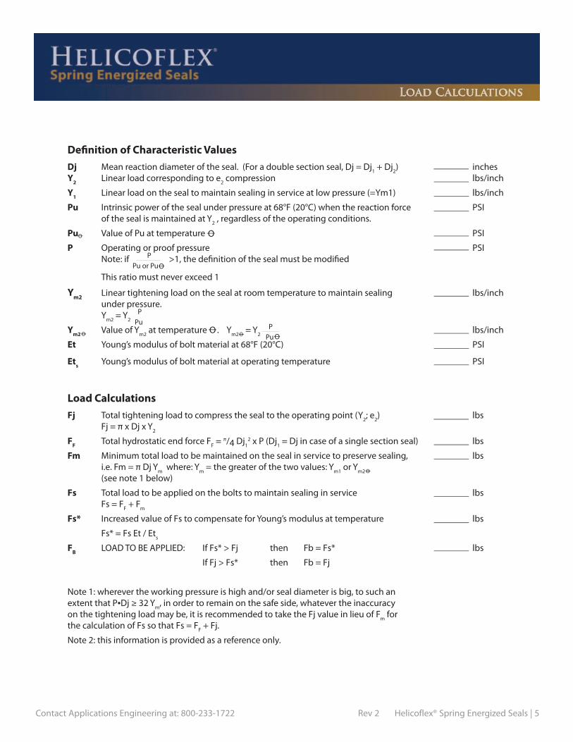
Dj Mean reaction diameter of the seal. (For a double section seal, Dj = Dj1 + Dj
2) inches
Y2 Linear load corresponding to e2 compression lbs/inch
Y1 Linear load on the seal to maintain sealing in service at low pressure (=Ym1) lbs/inch
Pu Intrinsic power of the seal under pressure at 68°F (20°C) when the reaction force PSI of the seal is maintained at Y
2 , regardless of the operating conditions.
Pu Value of Pu at temperature PSI
P Operating or proof pressure PSI Note: if >1, the defi nition of the seal must be modifi ed
This ratio must never exceed 1
Ym2 Linear tightening load on the seal at room temperature to maintain sealing lbs/inch under pressure. Y
m2 = Y
2
Ym2 Value of Ym2
at temperature . Ym2
= Y2 lbs/inch
Et Young’s modulus of bolt material at 68°F (20°C) PSI
Ets Young’s modulus of bolt material at operating temperature PSI
Load Calculations
PPu or Pu
PPu
PPu
Defi nition of Characteristic Values
Fj Total tightening load to compress the seal to the operating point (Y2; e
2) lbs
Fj = π x Dj x Y2
FF Total hydrostatic end force FF = π/4 Dj
12 x P (Dj
1 = Dj in case of a single section seal) lbs
Fm Minimum total load to be maintained on the seal in service to preserve sealing, lbs i.e. Fm = π Dj Y
m where: Y
m = the greater of the two values: Y
m1 or Y
m2
(see note 1 below)
Fs Total load to be applied on the bolts to maintain sealing in service lbs Fs = F
F + F
m
Fs* Increased value of Fs to compensate for Young’s modulus at temperature lbs
Fs* = Fs Et / Ets
FB LOAD TO BE APPLIED: If Fs* > Fj then Fb = Fs* lbs
If Fj > Fs* then Fb = Fj
Note 1: wherever the working pressure is high and/or seal diameter is big, to such an extent that P•Dj ≥ 32 Y
m, in order to remain on the safe side, whatever the inaccuracy
on the tightening load may be, it is recommended to take the Fj value in lieu of Fm
for the calculation of Fs so that Fs = F
F + Fj.
Note 2: this information is provided as a reference only.
Load Calculations
OO
O
O
O
O
O
O

6 | Helicoflex® Spring Energized Seals Rev 2 Contact Applications Engineering at: 800-233-1722
Shaped SealsGroove design: Contact Applications Engineering for assistance in design-ing non-circular grooves.
Groove fi nish: Most applications will require a fi nish of 16-32 RMS (0.4 to 0.8 Ra µm). All machining & polishing marks must follow seal circumference.
Min. Seal Radius: The minimum seal bending radius is six times the seal cross section (CS).
Seating Load: The load (Y2) to seat the seal is approximately 30% higher due to a slightly stiff er spring design.
Flatness
0.350 to 20.00020.001 to 80.000
Seal Diameter Range Amplitude Tangential Slope Radial Slope
0.008 0.016
1:10002:1000
1:1002:100
Dimensions in inches
Seal/Groove Tolerances
0.350 to 2.0002.001 to 12.000
12.001 to 25.00025.001 to 48.00048.001 to 72.000
> 72.000
Seal Diameter Range Pressure <300psi (20 bar) Pressure ≥300 psi (20 bar)
0.0050.0100.0100.0150.020
Seal tolerancet
0.0050.0100.0100.0150.015
Groove toleranceh
Seal tolerancet
Groove toleranceh
0.0040.0040.0060.0080.010
0.0040.0040.0060.0080.008
Contact Applications Engineering
Seal and Groove Sizing CalculationsThe equations below can be used for basic groove calculations. Applications that have signifi cant thermal expansion may require additional clearance. Please contact Applications Engineering for design assistance.
Determining Seal Diameter:
Internal ExternalA = C-X B = D + X
Determining Groove Diameter:
Internal ExternalC = A + X D = B – X
Internal Pressure: Seal Type HN200
C
External Pressure: Seal Type HN220
A
+h-0.000
±t
G
√ C
F
G
BD+0.000
-h
±t
√ C
√ C
√ CF
Tolerancing: See chart
Where: A = Seal Outer Diameter B = Seal Inner Diameter C = Groove Outer Diameter D = Groove Inner Diameter X = Diametrical Clearance (see table)
Groove Finish √C: See groove dimensioning chart on page 7
Seal and Groove Dimensions

Contact Applications Engineering at: 800-233-1722 Rev 2 Helicoflex® Spring Energized Seals | 7
Seal and Groove Dimensions
Installation Seal Diametrical Diametrical Groove Groove Groove Free Compression Diameter Clearance Clearance Depth Width (Min.) Finish Height e2 Range X X F G RMS 0.063 0.024 0.500 to 4.000 0.024 0.012 0.039 +/- 0.003 0.111 0.075 0.028 0.625 to 6.000 0.028 0.012 0.047 +/- 0.003 0.131 0.087 0.028 0.750 to 10.000 0.028 0.012 0.059 +/- 0.003 0.143 0.098 0.028 0.875 to 15.000 0.028 0.012 0.070 +/- 0.003 0.154 32-125 0.118 0.031 1.000 to 20.000 0.031 0.012 0.087 +/- 0.004 0.180 0.138 0.031 1.250 to 25.000 0.031 0.020 0.107 +/- 0.004 0.200 Contact
0.157 0.035 1.750 to 30.000 0.035 0.020 0.122 +/- 0.004 0.227 Applications
0.177 0.035 2.000 to 40.000 0.035 0.020 0.142 +/- 0.004 0.247 Engineering
0.197 0.035 3.000 to 50.000 0.035 0.020 0.162 +/- 0.004 0.267 for 0.217 0.035 4.000 to 50.000 + 0.035 0.020 0.182 +/- 0.004 0.287 Recommendation
0.236 0.039 5.000 to 50.000 + 0.039 0.020 0.197 +/- 0.005 0.314 0.276 0.039 6.000 to 50.000 + 0.039 0.028 0.237 +/- 0.005 0.354 0.315 0.039 8.000 to 50.000 + 0.039 0.028 0.276 +/- 0.005 0.393 0.063 0.020 0.500 to 4.000 0.020 0.012 0.043 +/- 0.002 0.103 0.075 0.024 0.625 to 6.000 0.024 0.012 0.051 +/- 0.003 0.123 0.087 0.024 0.750 to 10.000 0.024 0.012 0.063 +/- 0.003 0.135 0.098 0.028 0.875 to 15.000 0.028 0.012 0.070 +/- 0.003 0.154 63-125 0.118 0.031 1.000 to 20.000 0.031 0.012 0.087 +/- 0.004 0.180 0.138 0.031 1.250 to 25.000 0.031 0.020 0.107 +/- 0.004 0.200 Contact
0.157 0.031 1.750 to 30.000 0.031 0.020 0.126 +/- 0.004 0.219 Applications
0.177 0.031 2.000 to 40.000 0.031 0.020 0.146 +/- 0.004 0.239 Engineering
0.197 0.031 3.000 to 50.000 0.031 0.020 0.166 +/- 0.004 0.259 for
0.217 0.031 4.000 to 50.000 + 0.031 0.020 0.186 +/- 0.004 0.279 Recommendation
0.236 0.035 5.000 to 50.000 + 0.035 0.020 0.201 +/- 0.004 0.306 0.276 0.035 6.000 to 50.000 + 0.035 0.028 0.241 +/- 0.004 0.346 0.315 0.035 8.000 to 50.000 + 0.035 0.028 0.280 +/- 0.004 0.385 0.063 0.020 0.500 to 4.000 0.020 0.012 0.043 +/- 0.002 0.103 0.075 0.024 0.625 to 6.000 0.024 0.012 0.051 +/- 0.003 0.123 0.087 0.024 0.750 to 10.000 0.024 0.012 0.063 +/- 0.003 0.135 0.098 0.028 0.875 to 15.000 0.028 0.012 0.070 +/- 0.003 0.154 63-125 0.118 0.028 1.000 to 20.000 0.028 0.012 0.090 +/- 0.003 0.174 0.138 0.028 1.250 to 25.000 0.028 0.020 0.110 +/- 0.003 0.194 Contact
0.157 0.031 1.750 to 30.000 0.031 0.020 0.126 +/- 0.004 0.219 Applications
0.177 0.031 2.000 to 40.000 0.031 0.020 0.146 +/- 0.004 0.239 Engineering
0.197 0.031 3.000 to 50.000 0.031 0.020 0.166 +/- 0.004 0.259 for 0.217 0.031 4.000 to 50.000 + 0.031 0.020 0.186 +/- 0.004 0.279 Recommendation
0.236 0.035 5.000 to 50.000 + 0.035 0.020 0.201 +/- 0.004 0.306 0.276 0.035 6.000 to 50.000 + 0.035 0.028 0.241 +/- 0.004 0.346 0.315 0.035 8.000 to 50.000 + 0.035 0.028 0.280 +/- 0.004 0.385 0.063 0.016 0.500 to 4.000 0.016 0.012 0.047 +/- 0.002 0.095 0.075 0.020 0.625 to 6.000 0.020 0.012 0.055 +/- 0.002 0.115 0.087 0.020 0.750 to 10.000 0.020 0.012 0.067 +/- 0.002 0.127 0.098 0.024 0.875 to 15.000 0.024 0.012 0.074 +/- 0.003 0.146 32-63 0.118 0.024 1.000 to 20.000 0.024 0.012 0.094 +/- 0.003 0.166 0.138 0.024 1.250 to 25.000 0.024 0.020 0.114 +/- 0.003 0.186 Contact 0.157 0.028 1.750 to 30.000 0.028 0.020 0.129 +/- 0.003 0.213 Applications
0.177 0.028 2.000 to 40.000 0.028 0.020 0.149 +/- 0.003 0.233 Engineering
0.197 0.028 3.000 to 50.000 0.028 0.020 0.169 +/- 0.003 0.253 for
0.217 0.028 4.000 to 50.000 + 0.028 0.020 0.189 +/- 0.003 0.273 Recommendation
0.236 0.031 5.000 to 50.000 + 0.031 0.020 0.205 +/- 0.004 0.298 0.276 0.031 6.000 to 50.000 + 0.031 0.028 0.245 +/- 0.004 0.338 0.315 0.031 8.000 to 50.000 + 0.031 0.028 0.284 +/- 0.004 0.377 0.063 0.016 0.500 to 4.000 0.016 0.012 0.047 +/- 0.002 0.095 0.075 0.020 0.625 to 6.000 0.020 0.012 0.055 +/- 0.002 0.115 0.087 0.020 0.750 to 10.000 0.020 0.012 0.067 +/- 0.002 0.127 0.098 0.024 0.875 to 15.000 0.024 0.012 0.074 +/- 0.003 0.146 32-63 0.118 0.024 1.000 to 20.000 0.024 0.012 0.094 +/- 0.003 0.166 0.138 0.024 1.250 to 25.000 0.024 0.020 0.114 +/- 0.003 0.186 Contact
0.157 0.028 1.750 to 30.000 0.028 0.020 0.129 +/- 0.003 0.213 Applications
0.177 0.028 2.000 to 40.000 0.028 0.020 0.149 +/- 0.003 0.233 Engineering
0.197 0.028 3.000 to 50.000 0.028 0.020 0.169 +/- 0.003 0.253 for 0.217 0.028 4.000 to 50.000 + 0.028 0.020 0.189 +/- 0.003 0.273 Recommendation 0.236 0.031 5.000 to 50.000 + 0.031 0.020 0.205 +/- 0.004 0.298 0.276 0.031 6.000 to 50.000 + 0.031 0.028 0.245 +/- 0.004 0.338 0.315 0.031 8.000 to 50.000 + 0.031 0.028 0.284 +/- 0.004 0.377
Aluminum
Silver
Copper, Soft Iron,
Mild Steels
and Annealed
Nickel
Nickel, Monel,
Tantalum
Stainless Steel,
Inconel, Titanium
Jacket Material
SEAL GROOVEPressure < 300psi Pressure ≥ 300psi
Dimensions in inches

8 | Helicoflex® Spring Energized Seals Rev 2 Contact Applications Engineering at: 800-233-1722
Three Face Compression
CALCULATIONS COEFFICIENT VALUES
Coeffi cient 30º 45º 60º a 2.0 1.4 1.15 K 0.9 1.2 1.4 �������������
��
“h” Values
0.1020.1260.1650.2050.252
Seal Cross Section 30º 45º 60º
CS
0.1300.1570.2070.2600.321
AluminumJacket
Other Jackets
AluminumJacket
Other Jackets
AluminumJacket
Other Jackets
0.1260.1570.2070.2600.321
0.1630.1990.2600.3270.402
0.1570.1990.2600.3270.402
0.1260.1570.2130.2720.339
0.1340.1650.2200.2800.346
Dimensions in inches
Target Sealing Criteria The ultimate leak rate of a joint is a function of the seal design, fl ange design, bolting, surface fi nish and other factors. Helicofl ex seals are designed to provide two levels of service: Helium Sealing or Bubble Sealing.
Helium Sealing: These Helicofl ex seals are designed with a target Helium leak rate not to exceed 1x10⁻⁹ cc/sec.atm under a ∆P of 1 atmosphere. The ultimate leak rate will depend on the factors listed above.
Bubble Sealing: These Helicofl ex seals are designed with a target air leak rate not to exceed 1x10⁻⁴ cc/sec.atm
under a ∆P of 1 atmosphere.
Seal and Groove Dimensions
���
�
�
�����������
������������
J J
E = Shaft OD +0.000-0.002 A = Seal ID +0.002
-0.000
30º Type HN140-240 45º Type HN140-240 60º Type HN100-200
º
Axial Load (Ya) = K • Y2
Shaft OD (E) = Seal ID (A)Clearance (J) < CS / 10Axial Compression (e) = a • e2
Cavity Finish < 32 RMS

Contact Applications Engineering at: 800-233-1722 Rev 2 Helicoflex® Spring Energized Seals | 9
0.0630.1020.1260.1650.2050.252
0.0080.0100.0120.0160.0160.018
228308343434525640
Axial Pressure
Seal Confi guration = HN110 or HN210
0.0630.1020.1180.1570.2000.260
Aluminum
Cross SectionCS
e3
Ya lbs/in
0.0120.0140.0160.0200.0200.024
109137154183206235
Silver Copper
0.0630.1020.1220.1650.2050.244
Cross SectionCS
e3
Ya lbs/in
0.0100.0120.0140.0180.0180.020
170195206228263308
0.0670.0920.1280.1710.2100.250
Cross SectionCS
e3
Ya lbs/in
0.0080.0100.0120.0160.0160.018
217251286332377457
Nickel
CALCULATIONS
Seal and Groove Dimensioning
Ø Seal OD+0.000-0.002+0.002-0.000
Ø Cavity OD
G +0.000-0.004
Ø Shaft OD1
L
+0.002-0.002
Ø Shaft OD2
CL
CL
L
+0.002-0.002
Ø Housing OD2
+0.004-0.000
Ø Housing OD1
+0.002-0.000Ø Seal ID
+0.000-0.002
Ø Cavity ID
G
Internal Compression External Compression
Dimensions in inches
Cross SectionCS
e3
Ya lbs/in
Internal Compression External Compression
G min = CS + e3 + 0.008 Seal OD = Cavity OD Seal ID = Cavity ID
L min = 10 x e3 Seal ID = Seal OD - 2 CS Seal OD = Seal ID + 2 CS
Cavity Finish: ≤ 32RMS Shaft OD1 ≤ Seal ID Housing OD1 ≥ Seal ODYa = Axial Seating Load Shaft OD2 = Seal ID + 2e
3 Housing OD2 = SealOD - 2e
3

10 | Helicoflex® Spring Energized Seals Rev 2 Contact Applications Engineering at: 800-233-1722
ANSI B16.5 Raised Face Flange The Helicofl ex® HN208 is ideally suited for standard raised face fl anges. The resilient nature of the seal allows it to compensate for the extremes of high temperature and pressure where traditional spiral wounds and double jacketed seals fail. The jacket and spring combination can be modifi ed to meet most requirements of temperature and pressure. In addition, a large selection of jacket materials en-sures chemical compatibility in corrosive and caustic media.
����������������������������
������
Cross Seating Recommended Section Load Flange Jacket Availability (inches) (lbs/in)* Finish (RMS)
Aluminum Standard 0.160 1150 63 - 125 Silver Standard 0.160 1725 63 - 125 Copper Standard 0.155 2250 63 - 125 Soft Iron Optional 0.155 2250 32 - 63 Nickel Standard 0.150 2800 32 - 63 Monel Optional 0.150 2800 32 - 63 Hastelloy C Optional 0.150 3800 32 - 63 Stainless Steel Standard 0.150 3800 32 - 63 Alloy 600 Optional 0.150 3800 32 - 63 Alloy X750 Optional 0.150 4000 32 - 63 Titanium Optional 0.150 4000 32 - 63
Seal Type HN208
*NOTE: Seating load only! Does not allow for hydrostatic end force.
SEAL DIMENSIONS
Nominal Mean Seal OD (A)
Diameter Diameter (d) 150lb 300lb 400lb 600lb 900lb 1500lb 2500lb 1/2 0.827 1.874 2.126 2.126 2.126 2.500 2.500 2.752 3/4 1.102 2.252 2.626 2.626 2.626 2.752 2.752 3.000 1 1.417 2.626 2.874 2.874 2.874 3.122 3.122 3.374 1-1/4 1.890 3.000 3.252 3.252 3.252 3.500 3.500 4.126 1-1/2 2.283 3.374 3.752 3.752 3.752 3.874 3.874 4.626 2 2.913 4.126 4.374 4.374 4.374 5.626 5.626 5.752 2-1/2 3.425 4.874 5.126 5.126 5.126 6.500 6.500 6.626 3 4.173 5.374 5.874 5.874 5.874 6.626 6.874 7.752 3-1/2 4.685 6.374 6.500 6.500 6.374 N/A N/A N/A 4 5.256 6.874 7.126 7.000 7.626 8.126 8.252 9.252 5 6.378 7.752 8.500 8.374 9.500 9.752 10.000 11.000 6 7.500 8.752 9.874 9.752 10.500 11.413 11.126 12.500 8 9.567 10.996 12.126 12.000 12.626 14.126 13.874 15.252 10 11.693 13.374 14.252 14.126 15.752 17.126 17.126 18.760 12 13.858 16.126 16.626 16.500 18.000 19.626 20.500 21.626 14 15.098 17.752 19.126 19.000 19.374 20.500 22.752 N/A 16 17.205 20.252 21.252 21.126 22.252 22.626 25.252 N/A 18 19.567 21.626 23.500 23.374 24.126 25.126 27.752 N/A 20 21.575 23.874 25.752 25.500 26.874 27.500 29.752 N/A 24 25.728 28.252 30.500 30.252 31.126 32.996 35.500 N/A
NOTE: Contact Applications Engineering for other available sizes and materials
Raised Face Flanges
Dimensions in inches
Dimensions in inches

Contact Applications Engineering at: 800-233-1722 Rev 2 Helicoflex® Spring Energized Seals | 11
Code Calculations
Operatingload
Hydrostatic force
Minimumservice load
Minimum tightening
load to applyon bolts
Calculations According to Codes
A.S.M.E. Section VIII Division I Garlock Helicofl ex
Wm2 = π.b.G.y
HP = 2.b.π.G.m.P
W =(1) W
m2
(2) H + Hp = Wm1
Use the greater of the two (1) or (2)
Fj = π.Dj.Y2
FF = π. .P(Dj)2
4
Fm= π.Dj.Ym
Use the greater of the two
FB =
(1) Fj(2) F
F + F
m = Fs
Use the greater of the two (1) or (2)
Operatingload
Hydrostatic force
Minimumservice load
Minimum bolt load
Equivalent Symbols
A.S.M.E. Section VIII Division I
Wm2
= Fj b = 1
G = Dj Y = Y
2
Wm2
= π.Dj.Y2
H = FF
G = Dj
H = π. .P(Dj)2
4
Hp = F
m
b = 1 G = Dj
2.m.P = Ym
m =
HP = π.Dj.Ym
Ym2.P
W = FB
W = (1) Fj (2) F
F + F
m = Fs
Use the greater of the two (1) or (2)
Note: Due to its circular section, the Helicofl ex seal exhibits a “line” load instead of an “area load” typical of traditional gaskets. As a result, “m”, “b” and “y” factors are not pertinent when applied to the Helicofl ex seal. These equivalent equations were developed to assist fl ange designers with their calculations.
H = π. .PG2
4
O
Ym1 = Y
1
Ym2 = Y
2
PPu
Ym =

HELICOFLEX DATA SHEETTel: 800-233-1722 Fax: 803-783-4279
E-Mail: [email protected]
COMPANY: PHONE:
CONTACT: FAX:
ADDRESS: E-MAIL:
DATE:
APPLICATION: (please attach customer drawing / sketch)
Brief Description:
Annual quantities: RFQ Quantities:
Is This a New Design? ❏ Yes ❏ No Are Modifications Possible? ❏ Yes ❏ No
Drawing or Sketch Attached? ❏ Yes ❏ No What is the Seal Type? ❏ Shaped ❏ Circular
SERVICE CONDITIONS:
Media: Life Expectancy:
Working Temperature: Max/Proof Pressure: @ Temp. =
Working Pressure: Max Temperature: @ Pressure =
Helium: Std.cc/sec
Pressure Cycles: Flow Rate: cc/minute
Other:
FLANGE DETAILS: (Please Provide Drawing)
Radial: Axial: #Cycles:
Material: Thickness:
Size: # Rating: Face Surface Finish: (RMS)
Standard: Size:
Description: (Please Provide Drawing)
GROOVE DETAILS: (Please Provide Drawing)
Type (Rectangular, Dovetail, etc.):
Outer Diameter: Tolerance: Depth: Tolerance:
Inner Diameter: Tolerance: Finish (RMS) Type:
BOLTING DETAILS: (Please Provide Drawing)
Size: Type / Grade:
Number: Tapped / Through:
OTHER:
Pressure Direction: (Internal/External/Axial)
Temperature Cycles:
Target Sealing Level:
Amount of Flange Movment in Service: (Inches)
❏ Groove / Counter Bore:
❏ ANSI Raised Face
❏ Flange(s) with Clamping System: (ISO,KF, etc)
❏ Other:
Please list dimensions in Groove Details section
Finish Type: lathe (circular), endmill (multi-directional), other
Bolt Circle
Special coating / plating specification:
Special quality / inspection specifications:
Other:

Contact Applications Engineering at: 800-233-1722 Rev 2 Helicoflex® Spring Energized Seals | 13
The technical data contained herein is by way of example and should not be relied on for any spe-cific application. Garlock Helicoflex will be pleased to provide specific technical data or specifica-tions with respect to any customer’s particular applications. Use of the technical data or specifica-tions contained herein without the express written approval of Garlock Helicoflex is at user’s risk and Garlock Helicoflex expressly disclaims responsibility for such use and the situations which may result therefrom. Garlock Helicoflex makes no warranty, express or implied, that utilization of the technol-ogy or products disclosed herein will not infringe any industrial or intellectual property rights of third parties. Garlock Helicoflex is constantly involved in engineering and development. Accordingly, Garlock Helicoflex reserves the right to modify, at any time, the technology and product specifica-tions contained herein. All technical data, specifications and other information contained herein is deemed to be the proprietary intellectual property of Garlock Helicoflex. No reproduction, copy or use thereof may be made without the express written consent of Garlock Helicoflex.


Contact Applications Engineering at: 800-233-1722 Rev 2 Delta® Spring Energized Metal Seals | 1
The Delta® seal is a member of the Helicoflex fam-ily of spring energized seals. The sealing principle of the Helicoflex family of seals is based upon the plastic deformation of a jacket that has greater ductility than the flange materials. This occurs between the sealing face of a flange and an elastic core composed of a close-wound helical spring. The spring is selected to have a specific compres-sion resistance. During compression, the resulting specific pressure forces the jacket to yield and ensures positive contact with the flange sealing faces. Each coil of the helical spring acts independently and allows the seal to conform to irregularities on the flange surface.
Sealing Concept
The Delta® seal is unique in that it uses two small ridges or “Deltas” on the face of the seal. The load required to plastically deform the jacket material is greatly reduced by concen-trating the compression load on the Deltas. The resulting high contact stress in the seal track makes the Delta seal an excellent choice for ultra-high vacuum applications that require ultra-low Helium leak rates. There is typically no risk of damaging the flange seal-ing surfaces as long as the minimum hardness requirements are maintained.
Outer Jacket
Inner Lining
Helical Spring
Delta®

2 | Delta® Spring Energized Metal Seals Rev 2 Contact Applications Engineering at: 800-233-1722
Performance Data
NOTE: Actual spring back and load will vary based on material, geometry, and spring design.
Typical Load Defl ection Curve
Load
Deflection
Y2
Useful Elastic Recovery
Permanent Deformation e
2
Load at OptimumCompression
OptimumCompression
Total Spring Back
Leak PerformanceDelta seals can provide Helium leak rate performance of < 1x10-11 std.cc/sec (per meter of seal circumference). Actual leak rate will depend on seal jacket, cavity/flange finish, bolting, hardware robustness and cleanliness level.
Classification of Seal Type
HNV 2 0 0Cross Section
Type# Jackets/
LiningJacket
OrientationSection
Orientation
CrossSectionType
HNV low load (Delta Seal)
Jacket/ 1 = jacket only 2 = jacket with inner liningLining
JacketOrientation
SectionOrientation — — —
Example
0 1 2 3 4 5 6 7 8 9
— — — — —
0 1 2 3 4 5 6 7 8 9

Contact Applications Engineering at: 800-233-1722 Rev 2 Delta® Spring Energized Metal Seals | 3
Delta® Characteristic Values
NOTES:1. PCI = Pounds force per circumferential inch. 2. Seating load (Y
2) is an approximation and may vary based on groove clearance, seal diameter
and tolerance. Seating load is for circular seals only. 3. The customer must verify that system bolts and flanges can generate the required seating load without warping or distorting.4. The customer must test and verify that the seal design meets customer designated performance requirements.5. Seal type HNV100 is available as an option only. Type HNV200 is preferred due to its protective inner lining and can be expected to produce better results.6. Contact Applications Engineering for low pressure applications.
SealType
FreeHeight
SealDiameter
Aluminum
Silver
Copper
Seating LoadPCI
InstallationCompression
e2
0.075
0.102
0.130
0.157
0.189
0.220
0.264
0.067
0.094
0.122
0.154
0.185
0.213
0.256
0.065
0.092
0.120
0.155
0.179
0.210
0.250
0.065
0.092
0.120
0.155
0.179
0.210
0.250
MaximumTemperature
ºF ºC
HNV100
HNV200
HNV200
HNV200
HNV200
HNV200
HNV200
HNV100
HNV200
HNV200
HNV200
HNV200
HNV200
HNV200
HNV100
HNV200
HNV200
HNV200
HNV200
HNV200
HNV200
HNV100
HNV200
HNV200
HNV200
HNV200
HNV200
HNV200
0.028
0.031
0.035
0.035
0.039
0.043
0.024
0.024
0.028
0.031
0.031
0.035
0.017
0.021
0.025
0.025
0.025
0.029
0.017
0.021
0.025
0.025
0.025
0.029
0.750 to 8.000
1.000 to 16.000
2.000 to 20.000
3.000 to 30.000
4.000 to 40.000
5.000 to 50.000
0.750 to 6.000
1.000 to 12.000
2.000 to 18.000
3.000 to 20.000
4.000 to 20.000
5.000 to 20.000
0.750 to 8.000
1.000 to 16.000
2.000 to 18.000
3.000 to 20.000
4.000 to 30.000
5.000 to 30.000
0.750 to 8.000
1.000 to 16.000
2.000 to 18.000
3.000 to 20.000
4.000 to 30.000
5.000 to 30.000
800
800
800
800
860
860
915
915
915
915
970
1030
1030
1030
1030
1030
1030
1085
1030
1030
1030
1030
1030
1085
428
482
536
536
608
644
536
572
662
698
752
842
716
716
788
842
896
968
788
896
1022
1112
1202
1202
220
250
280
280
320
340
280
300
350
370
400
450
380
380
420
450
480
520
420
480
550
600
650
650
Nickel(Annealed)
StainlessSteel
Y2
Contact Applications Engineering
Performance Data
Dimensions in inches
Contact Applications Engineering
Contact Applications Engineering
Contact Applications Engineering
Contact Applications Engineering
JacketMaterial

4 | Delta® Spring Energized Metal Seals Rev 2 Contact Applications Engineering at: 800-233-1722
Internal Vacuum: Seal Type HNV200
C
External Vacuum: Seal Type HNV220
B
+h-0.000
± t
G
G
F
Seal and Groove Sizing CalcuationsThe equations below can be used for basic groove calculations. Applications that have signifi cant thermal expansion may require additional clearance. Please contact Applications Engineering for design assistance.
Determining Seal Diameter:
Internal Vacuum External Vacuum< 12” B = C - X - 2 (Seal Section x 0.933) A = C - X≥ 12” Contact Applications Engineering
Determining Groove Diameter:
Internal Vacuum External Vacuum< 12” C = B + X + 2 (Seal Section x 0.933) C = A + X≥ 12” Contact Applications Engineering
Tolerancing: See chart
Where: A = Seal Outer Diameter B = Seal Inner Diameter C = Groove Outer Diameter X = Diametrical Clearance
16√C
16√C
CA
+h-0.000
± t
16√C
16√C
Seal and Groove Dimensions
F

Contact Applications Engineering at: 800-233-1722 Rev 2 Delta® Spring Energized Metal Seals | 5
Delta® Groove Dimensions
NOTES: 1. Contact Applications Engineering for additional sizes.2. Seal type HNV100 is available as an option only. Type HNV200 is preferred due to its protective inner lining and can be expected to produce better results.3. Seal diameters ≥ 12” may require special tolerancing. Contact Applications Engineering for design assistance.
FreeHeight
Seal Type
Aluminum
Silver
Copper
0.075
0.102
0.130
0.157
0.189
0.220
0.264
0.067
0.094
0.122
0.154
0.185
0.213
0.256
0.065
0.092
0.120
0.155
0.179
0.210
0.250
0.065
0.092
0.120
0.155
0.179
0.210
0.250
SeatingLoadPCI Y
2
800
800
800
800
860
860
915
915
915
915
970
1030
1030
1030
1030
1030
1030
1085
1030
1030
1030
1030
1030
1085
Nickel(Annealed)
StainlessSteel Contact Applications Engineering
SealTolerance
t3
0.005
0.005
0.005
0.005
0.005
0.005
0.005
0.005
0.005
0.005
0.005
0.005
0.005
0.005
0.005
0.005
0.005
0.005
0.005
0.005
0.005
0.005
0.005
0.005
GrooveTolerance
h
0.010
0.010
0.010
0.010
0.010
0.010
0.010
0.010
0.010
0.010
0.010
0.010
0.010
0.010
0.010
0.010
0.010
0.010
0.010
0.010
0.010
0.010
0.010
0.010
GrooveDepth
F
0.075 ± 0.002
0.099 ± 0.002
0.122 ± 0.002
0.154 ± 0.003
0.180 ± 0.003
0.220 ± 0.003
0.070 ± 0.002
0.098 ± 0.002
0.126 ± 0.002
0.154 ± 0.003
0.180 ± 0.003
0.220 ± 0.003
0.075 ± 0.001
0.098 ± 0.002
0.130 ± 0.002
0.154 ± 0.002
0.185 ± 0.002
0.220 ± 0.003
0.075 ± 0.001
0.098 ± 0.002
0.130 ± 0.003
0.154 ± 0.002
0.185 ± 0.002
0.220 ± 0.003
SealDiameter
Range
0.750 to 8.000
1.000 to 16.000
2.000 to 20.000
3.000 to 30.000
4.000 to 30.000
5.000 to 30.000
0.750 to 6.000
1.000 to 12.000
2.000 to 18.000
3.000 to 20.000
4.000 to 20.000
5.000 to 20.000
0.750 to 8.000
1.000 to 16.000
2.000 to 18.000
3.000 too 20.000
4.000 to 30.000
5.000 to 30.000
0.750 to 8.000
1.000 to 16.000
2.000 to 18.000
3.000 to 20.000
4.000 to 30.000
5.000 to 30.000
Min. FlangeHardness(Vickers)
65
65
65
65
65
65
120
120
120
120
120
120
130
130
130
130
130
130
220
220
220
220
220
220
Contact Applications Engineering
Seal Groove
HNV100
HNV200
HNV200
HNV200
HNV200
HNV200
HNV200
HNV100
HNV200
HNV200
HNV200
HNV200
HNV200
HNV200
HNV100
HNV200
HNV200
HNV200
HNV200
HNV200
HNV200
HNV100
HNV200
HNV200
HNV200
HNV200
HNV200
HNV200
GrooveWidth
G (Min)
0.150
0.180
0.210
0.245
0.280
0.320
0.140
0.165
0.200
0.235
0.265
0.315
0.130
0.160
0.200
0.225
0.255
0.300
0.130
0.160
0.200
0.225
0.255
0.300
Seal and Groove Dimensions
DiameticalClearance
x
0.020
0.030
0.030
0.035
0.040
0.040
0.020
0.020
0.025
0.030
0.030
0.035
0.020
0.020
0.025
0.025
0.025
0.030
0.020
0.020
0.025
0.025
0.025
0.030
Contact Applications Engineering
Contact Applications Engineering
Contact Applications Engineering
Contact Applications Engineering-
-
-
-
JacketMaterial
-
-
-
-
Seal Section
0.079
0.106
0.134
0.161
0.193
0.228
0.272
0.071
0.098
0.126
0.157
0.189
0.220
0.264
0.069
0.096
0.124
0.159
0.183
0.218
0.257
0.069
0.096
0.124
0.159
0.183
0.218
0.257

6 | Delta® Spring Energized Metal Seals Rev 2 Contact Applications Engineering at: 800-233-1722
NOTES: 1. PCI = Pounds force per circumferential inch. 2. Seating Load (Y
2) is an approximation and may vary based on groove clearance, seal diameter
and tolerance. Load values may be slightly higher in corner radii. 3. Seal type HNV100 is available as an option only. Type HNV200 is preferred due to its protective inner lining and can be expected to produce better results.4. Seal Tolerance: Seal is manufactured to fit customer supplied/purchased groove template.5. All machining and polishing marks must follow seal circumference.
Groove OD +h-0.000
Groove OD
+h-0.000
R Seal ID
A A
G
16√C
Free Height
g
F
Section AA
Shaped Seal: Delta® Groove Dimensions
SealSection
gFree
HeightSeal Type
Aluminum
Silver
Copper
0.075
0.102
0.130
0.157
0.189
0.220
0.264
0.067
0.094
0.122
0.154
0.185
0.065
0.092
0.120
0.155
0.179
0.065
0.092
0.120
0.155
0.179
0.079
0.106
0.134
0.161
0.194
0.228
0.272
0.071
0.098
0.126
0.157
0.189
0.069
0.096
0.124
0.159
0.183
0.069
0.096
0.124
0.159
0.183
Seating LoadPCI Y
2
Nickel(Annealed)
StainlessSteel
Contact Applications Engineering
SealTolerance
t
Fit Template
Fit Template
Fit Template
Fit Template
Fit Template
Fit Template
Fit Template
Fit Template
Fit Template
Fit Template
Fit Template
Fit Template
Fit Template
Fit Template
Fit Template
Fit Template
Fit Template
Fit Template
GrooveTolerance
h
0.010
0.010
0.010
0.010
0.010
0.010
0.010
0.010
0.010
0.010
0.010
0.010
0.010
0.010
0.010
0.010
0.010
0.010
GrooveDepth
F
0.075 ± 0.002
0.099 ± 0.002
0.122 ± 0.002
0.154 ± 0.003
0.180 ± 0.003
0.220 ± 0.003
0.070 ± 0.002
0.098 ± 0.002
0.126 ± 0.002
0.154 ± 0.003
0.075 ± 0.001
0.098 ± 0.002
0.130 ± 0.002
0.154 ± 0.002
0.075 ± 0.001
0.098 ± 0.002
0.130 ± 0.003
0.154 ± 0.002
InstallationCompression
e2
0.028
0.031
0.035
0.035
0.039
0.043
0.024
0.024
0.028
0.031
0.017
0.021
0.025
0.025
0.017
0.021
0.025
0.025
Min. FlangeHardness(Vickers)
65
65
65
65
65
65
120
120
120
120
130
130
130
130
220
220
220
220
Seal Groove
HNV100
HNV200
HNV200
HNV200
HNV200
HNV200
HNV200
HNV100
HNV200
HNV200
HNV200
HNV200
HNV100
HNV200
HNV200
HNV200
HNV200
HNV100
HNV200
HNV200
HNV200
HNV200
GrooveWidth
G (Min)
0.170
0.200
0.230
0.265
0.300
0.340
0.160
0.185
0.220
0.225
0.150
0.180
0.220
0.245
0.150
0.180
0.220
0.245
Bend Radius
ID R (Min)
0.750
1.000
1.125
1.375
1.500
1.750
0.625
0.875
1.000
1.250
0.625
0.875
1.000
1.125
0.625
0.875
1.000
1.125
Contact Applications Engineering
Contact Applications Engineering
Contact Applications Engineering
Contact Applications Engineering
Shaped Seals
1200
1050
1050
1050
1170
1200
1050
1150
1100
1100
1100
1350
1275
1275
1100
1350
1275
1275
Contact Applications Engineering
Contact Applications Engineering
Contact Applications Engineering
Contact Applications Engineering
JacketMaterial

HELICOFLEX DATA SHEETTel: 800-233-1722 Fax: 803-783-4279
E-Mail: [email protected]
COMPANY: PHONE:
CONTACT: FAX:
ADDRESS: E-MAIL:
DATE:
APPLICATION: (please attach customer drawing / sketch)
Brief Description:
Annual quantities: RFQ Quantities:
Is This a New Design? ❏ Yes ❏ No Are Modifications Possible? ❏ Yes ❏ No
Drawing or Sketch Attached? ❏ Yes ❏ No What is the Seal Type? ❏ Shaped ❏ Circular
SERVICE CONDITIONS:
Media: Life Expectancy:
Working Temperature: Max/Proof Pressure: @ Temp. =
Working Pressure: Max Temperature: @ Pressure =
Helium: Std.cc/sec
Pressure Cycles: Flow Rate: cc/minute
Other:
FLANGE DETAILS: (Please Provide Drawing)
Radial: Axial: #Cycles:
Material: Thickness:
Size: # Rating: Face Surface Finish: (RMS)
Standard: Size:
Description: (Please Provide Drawing)
GROOVE DETAILS: (Please Provide Drawing)
Type (Rectangular, Dovetail, etc.):
Outer Diameter: Tolerance: Depth: Tolerance:
Inner Diameter: Tolerance: Finish (RMS) Type:
BOLTING DETAILS: (Please Provide Drawing)
Size: Type / Grade:
Number: Tapped / Through:
OTHER:
Pressure Direction: (Internal/External/Axial)
Temperature Cycles:
Target Sealing Level:
Amount of Flange Movment in Service: (Inches)
❏ Groove / Counter Bore:
❏ ANSI Raised Face
❏ Flange(s) with Clamping System: (ISO,KF, etc)
❏ Other:
Please list dimensions in Groove Details section
Finish Type: lathe (circular), endmill (multi-directional), other
Bolt Circle
Special coating / plating specification:
Special quality / inspection specifications:
Other:

8 | Delta® Spring Energized Metal Seals Rev 2 Contact Applications Engineering at: 800-233-1722
The technical data contained herein is by way of example and should not be relied on for any spe-cific application. Garlock Helicoflex will be pleased to provide specific technical data or specifica-tions with respect to any customer’s particular applications. Use of the technical data or specifica-tions contained herein without the express written approval of Garlock Helicoflex is at user’s risk and Garlock Helicoflex expressly disclaims responsibility for such use and the situations which may result therefrom. Garlock Helicoflex makes no warranty, express or implied, that utilization of the technol-ogy or products disclosed herein will not infringe any industrial or intellectual property rights of third parties. Garlock Helicoflex is constantly involved in engineering and development. Accordingly, Garlock Helicoflex reserves the right to modify, at any time, the technology and product specifica-tions contained herein. All technical data, specifications and other information contained herein is deemed to be the proprietary intellectual property of Garlock Helicoflex. No reproduction, copy or use thereof may be made without the express written consent of Garlock Helicoflex.

Contact Applications Engineering at: 800-233-1722 Rev 1 O-Flex™ Metal O-Rings | 1
O-Flex™ Metal O-Rings are designed to provide a sealing option for high pressure/temperature applications that require minimal spring back. The O-Flex™ is made from high strength metal tubing that is coiled, cut and welded to size. It is available in standard cross section increments of 1/32”. The O-Flex™ seating load can be adjusted to the application by varying the cross section and tubing wall thickness. Typical applications include Performance Engines, Plastic Extrusion/Molding, Military Specifications, Aerospace and Chemical Processing.
Sealing Concept
O-Flex™ Types
BasicThe basic O-Flex™ is designed for low to moderate pressure applications as high pressure may collapse the exposed tub-ing wall.
Self EnergizingThe Self-Energizing O-Flex™ is designed for high pres-sure applications. Small holes are drilled in the tubing wall exposed to the system pressure. These holes create an ener-gizing effect by allowing the pressure to enter the O-Flex™. As a result, the pressure inside the seal increases with the system pressure and minimizes the possibility of collapsing the exposed tubing wall.
Pressure FilledThe Pressure Filled O-Flex™ is designed for Performance Engine applications that require sealing at elevated pressure and temperature in a high cycling environment. The O-Flex™ is filled with an inert gas that increases in pressure propor-tional to increases in system temperature. This results in an energizing effect that partially offsets the loss of material strength in service.

2 | O-Flex™ Metal O-Rings Rev 1 Contact Applications Engineering at: 800-233-1722
NOTE: Actual spring back and load will vary based on material, geometry, and wall thickness. Please check characteristic chart for specific information.
O-Flex™ Characteristic Curve
Load
Deflection
Y2
Useful Elastic Recovery
Permanent Deformation e
2
Load at OptimumCompression
OptimumCompression
Total Spring Back
Material
SS 321
Alloy 600
Alloy X750
Alloy 718
Other
Status Temperature Heat Treatment
Standard
Standard
Standard
Optional
Material Selection
T < 700ºF
T < 1,000ºF
T < 1,100ºF
T < 1,200ºF
NA
NA
NA
NA
Contact Applications Engineering
Plating/Coating
PTFE
Silver
Silver w/ Gold strike
Nickel
None
Other
Status Standard Thickness Temperature Groove Finish*
Optional
Standard
Optional
Standard
-
Plating/Coating Selection
.001/.003
.001/.002
.001/.002
.001/.002
-
T < 500ºF
T < 800ºF
T < 1,200ºF
T < 1,600ºF
-
Contact Applications Engineering
16 - 32 RMS
16 - 63 RMS
16 - 63 RMS
16 - 32 RMS
< 16 RMS
* Groove fi nish must follow seal circumference (lathe turned fi nish). Contact Applications Engineering for non-standard thicknesses.
Performance Data
Dimensions in inches

Contact Applications Engineering at: 800-233-1722 Rev 1 O-Flex™ Metal O-Rings | 3
CHARACTERISTIC VALUES AT 70ºF
SS 321 Alloy 600 Alloy X-750
Free Height
Compressione
2
SealDiameter
Range
Material Thickness
Thin (T)Medium (M)
Heavy (H)
Seating Load(PCI)
Y2
Seating Load(PCI)
Y2
Seating Load(PCI)
Y2
0.032 0.0060.500
to4.000
0.006 T 457 503 594
0.010 M 1028 1131 1336
- H - - -
0.063 0.0120.500
to10.000
0.010 T 571 628 742
0.012 M 799 879 1039
0.014 H 1256 1382 1633
0.094 0.0201.000
to20.000
0.010 T 343 377 446
0.012 M 514 565 668
0.018 H 1313 1444 1707
0.125 0.0262.000
to40.000
0.010 T 343 377 446
0.020 M 1142 1256 1485
0.025 H 2056 2262 2673
0.156 0.0313.000
to50.000
- T - - -
0.020 M 857 943 1114
0.025 H 1428 1571 1856
0.188 0.0394.000
to60.000
- T - - -
0.020 M 657 723 854
0.032 H 2113 2324 2747
0.250 0.0515.000
to80.000
0.025 T 799 879 1039
0.032 M 1370 1507 1781
0.049 H 3026 3329 3934
O-Flex™ Characteristic Values
NOTES: 1. PCI = Pounds force per circumferential inch2. Seating Load (Y
2) is an approximation and may vary based on groove clearance, seal diameter, tolerance and
plating thickness. It does not allow for system pressure requirements and should be verifi ed for each application and seal size. 3. The customer must verify that system bolts and fl anges can generate the required seating load without warping or distorting. 4. The customer must test and verify that the seal design meets customer designated performance requirements.
Performance Data
Dimensions in inches

4 | O-Flex™ Metal O-Rings Rev 1 Contact Applications Engineering at: 800-233-1722
Seal and Groove Dimensions
Internal Pressure
C
External Pressure
A
+h-0.000+t-0.000
G
F
BD
+0.000-t+0.000-h
G
F
Seal and Groove Sizing CalculationsThe equations below can be used for basic groove calculations. Applications that have signifi cant thermal expansion may require additional clearance. Please contact Applications Engineering for design assistance.
Determining Seal Diameter:
Internal ExternalA = C-X-2Pmax B = D + X + 2Pmax
Determining Groove Diameter:
Internal ExternalC = A + X + 2Pmax D = B – X – 2Pmax
Tolerancing: See chartWhere: A = Seal Outer Diameter B = Seal Inner Diameter C = Groove Outer Diameter D = Groove Inner Diameter Pmax = Maximum Plating or Coating Thickness X = Diametrical Clearance
Groove Finish √c: See Plating/Coating Section
√C
√C
√C
√C

Contact Applications Engineering at: 800-233-1722 Rev 1 O-Flex™ Metal O-Rings | 5
Seal and Groove Dimensions
FreeHeight
0.032
0.063
0.094
0.125
0.157
0.188
0.250
Seal Diameter Range
Seal and Groove Dimensions
SEALSeal
Tolerancet
0.500 to 4.000
0.500 to 10.000
1.000 to 20.000
2.000 to 40.000
3.000 to 50.000
4.000 to 50.000
5.000 to 50.000
0.005
0.005
0.005
0.005
0.005
0.005
0.008
Diametrical Clearance
x
0.006
0.006
0.008
0.008
0.014
0.014
0.019
GrooveTolerance
h
0.004
0.004
0.004
0.004
0.006
0.006
0.008
GrooveDepth
F
0.026 ±0.001
0.051 ±0.001
0.073 ±0.002
0.099 ±0.002
0.125 ±0.002
0.149 ±0.002
0.199 ±0.002
GrooveWidth (Min.)
G
0.055
0.090
0.125
0.160
0.200
0.250
0.350
Aerospace Industry
Racing Industry
Contact Applications Engineering at: 800-233-1722 O-Flex™ Metal O-Rings | 5
Dimensions in inches
NOTE: Contact Applications Engineering for additional sizes.
GROOVE

6 | O-Flex™ Metal O-Rings Rev 1 Contact Applications Engineering at: 800-233-1722
Tube Tube S.steel Alloy Alloy Coatings Diameter 321 600 X750
Wall Thickness T M H T M H T M H
0.032” ● ▲ ▲ ▲ ▲ ● ▲ ▲ 0.063” ● ▲ ▲ ▲ ▲ ● ▲ ▲ 0.094” ● ● ▲ ● ▲ ● ● ▲ PTFE 0.125” ● ▲ ▲ ▲ ▲ ● ▲ ▲ 0.156” ■ ▲ ▲ ■ ▲ ▲ ■ ▲ ▲
0.188” ■ ● ▲ ■ ● ▲ ● ● ▲ 0.250” ▲ ▲ ▲ ▲ ▲ ▲ ▲ ▲ ▲
0.032” ● ● ▲ ● ● ▲ ● ● ▲ 0.063” ● ● ▲ ● ● ▲ ● ● ▲ 0.094” ■ ● ▲ ■ ● ▲ ● ● ▲ Silver 0.125” ■ ● ▲ ■ ● ▲ ● ● ▲ 0.156” ■ ● ▲ ■ ● ▲ ■ ● ▲ 0.188” ■ ● ▲ ■ ● ▲ ■ ● ▲ 0.250” ● ● ▲ ● ● ▲ ● ● ▲
Wall Thickness T M H T M H T M H
0.032” ■ ● ● ■ ● ● ■ ● ● 0.063” ■ ■ ● ■ ● ● ■ ● ● 0.094” ■ ■ ● ■ ■ ● ■ ■ ● Nickel 0.125” ■ ● ● ■ ● ● ■ ● ● 0.156” ■ ● ● ■ ● ● ■ ● ● 0.188” ■ ■ ● ■ ■ ● ■ ● ● 0.250” ■ ● ● ● ● ● ● ● ▲
Legend
■ : Q > 1.32 x 10⁻⁵ std.cc/sec He T: Thin
● : 1.32 x 10⁻⁹ < Q < 1.32 x 10⁻⁵ std.cc/sec He M: Medium
▲ : Q <1.32 x 10⁻⁹ std.cc/sec He H: Heavy
Q : Approximate leak rate per meter of circumference
Sealing Levels
0.032” ■ ■ ● ■ ■ ● ■ ● ● 0.063” ■ ■ ■ ■ ■ ● ■ ■ ● 0.094” ■ ■ ■ ■ ■ ● ■ ■ ● Non Plated 0.125” ■ ■ ● ■ ■ ● ■ ■ ● 0.156” ■ ■ ● ■ ■ ● ■ ■ ●
0.188” ■ ■ ● ■ ■ ● ■ ■ ● 0.250” ■ ● ● ■ ● ● ■ ● ●
Wall Thickness T M H T M H T M H
Wall Thickness T M H T M H T M H

Contact Applications Engineering at: 800-233-1722 Rev 1 O-Flex™ Metal O-Rings | 7
Military Standards
O-Flex™ Seals for Military Standards
Contact Applications Engineering at: 800-233-1722 O-Flex™ Metal O-Rings | 7

8 | O-Flex™ Metal O-Rings Rev 1 Contact Applications Engineering at: 800-233-1722
Tube 0.035 Dia.Tube 0.035 Diameter
Military StandardMS 9141 Gasket, metal O-ring, .035 tube x .006 wall, cresMS 9371 Gasket, metal O-ring, .035 tube x .006 wall, cres, silver plated 1. Ring shall be fl at within B. 2. *Preferred sizes. 3. Material: Corrosion and heat resistant steel tubing AMS 5570 or AMS 5576. 4. Finish weld fl ush with tube OD. Smooth blend within .125 of Weld. Dimensions at blend shall not be more than .003 below adjacent surfaces. 5. Finish: Silver plate AMS 2410 .0010-.0015 thick. Dimensions to be met before plating. Contact points permissible on ID of ring: (MS 9371 only) 6. Surface roughness: AS 291/ANSI B46.1 7. Manufacturing specifi cation: AMS 7325 8. Identifi cation: Mark MS part number and manufacturer’s identifi cation on container. 9. Dimensions in inches. 10. Do not use unassigned part numbers. 11. Contact Applications Engineering for design requirements.
Weld - See Note 4
+
Add to MS Number
A+.005-.000
B
-03
-04
-05
-06
-07
-08
-09
-10
-11
-12
-13
-14
.250 †
.281 †
.312 †
.344 †
.375 †
.406 †
.438 †
.469 †
.500
.562
.625*
.688
.020
.020
.020
.020
.020
.020
.020
.020
.020
.020
.020
.020
Add to MS Number
A+.005-.000
B
-15
-16
-17
-18
-19
-20
-21
-22
-23
-24
-25
-26
-27
.750*
.812
.875*
.938
1.000*
1.125
1.250
1.375
1.500*
1.625
1.750*
1.875
2.000*
.020
.020
.020
.020
.020
.020
.020
.020
.020
.020
.020
.020
0.20
Military Standards
16
Surface roughness lay must be in direction shown for this distance both sides
.038
.029 30º min
.038
.034After Forming
A
Dia
Round within B on dia. (in free state) when restrained dia. A shall be round within dia. limits
Dimensions in inches
† Contact Applications Engineering for these sizes.

Contact Applications Engineering at: 800-233-1722 Rev 1 O-Flex™ Metal O-Rings | 9
Tube 0.062 Dia.Tube 0.062 Diameter
Military StandardMS 9142 Gasket, metal O-ring, .062 tube x .006 wall, cresMS 9202 Gasket, metal O-ring, .062 tube x .010 wall, cresMS 9372 Gasket, metal O-ring, .062 tube x .006 wall, cres, silver platedMS 9373 Gasket, metal O-ring, .062 tube x .010 wall, cres, silver plated 1. Ring shall be fl at within B. 2. *Preferred sizes. 3. Material: Corrosion and heat resistant steel tubing AMS 5570 or AMS 5576. 4. Finish weld fl ush with tube OD. Smooth blend within .125 of Weld. Dimensions at blend shall not be more than .004 below adjacent surfaces. 5. Finish: Silver plate AMS 2410 .0010-.0015 thick. Dimensions to be met before plating. Contact points permissible on ID of ring: (MS 9372, MS 9373 only) 6. Surface roughness: AS 291/ANSI B46.1 7. Manufacturing specifi cation: AMS 7325 8. Identifi cation: Mark MS part number and manufacturer’s identifi cation on container. 9. Dimensions in inches. 10. Do not use unassigned part numbers. 11. Contact Applications Engineering for design requirements.
Add to MS
Number
A+.005-.000
B
-013-014-015-016-017-018-019-020-021-022-023-024-025-026-027-028-029-030-031-032-033-034-035-036
Military Standards
.438*.469.500*.531.562*.594.625*.656.688*.719.750*.781.812.844.875*.906.938.969
1.000*1.0311.0621.0941.125*1.156
.030
.030
.030
.030
.030
.030
.030
.030
.030
.030
.030
.030
.030
.030
.030
.030
.030
.030 .030.030.030.030.030.030
Add to MS
Number
A+.005-.000
B
-037-038-039-040-041-042-043-044-045-046-047-048-049-050-051-052-053-054-055-056-057-058-059-060
1.1881.2191.250*1.3121.375*1.4381.500*1.5621.625*1.6881.750*1.8121.8751.9382.000*2.0622.1252.1882.250*2.3122.3752.4382.500*2.562
.030
.030
.030
.030
.030
.030
.030
.030
.030
.030
.030
.030
.030
.030
.030
.030
.030
.030
.030
.030
.030
.030
.030
.060
Add to MS
Number
A+.005-.000
B
-061-062-063-064-065-066-067-069-071-073-075-077-079-081-083-085-087-089-091-093-095-097-099-101
2.6252.6882.750*2.8122.8752.9383.000*3.1253.2503.3753.500*3.6253.7503.8754.000*4.1254.2504.3754.500*4.6254.7504.8755.000*5.125
.060
.060
.060
.060
.060
.060
.060
.060
.060
.060
.060
.060
.060
.060
.060
.060
.060
.060
.060
.060
.060
.060
.060
.090
Add to MS
Number
A+.005-.000
B
-103-105-107-109-111-113-115-117-119-121-123-125-127-129-131-133-135-137-139-141-143-145-147
5.2505.3755.5005.6255.7505.8756.000*6.1256.2506.3756.5006.6256.7506.8757.000*7.1257.2507.3757.5007.6257.7507.8758.000*
.090
.090
.090
.090
.090
.090
.090
.090
.090
.090
.090
.090
.090
.090
.090
.090
.090
.090
.090
.090
.090
.090
.090
Weld - See Note 4
+
16
Surface roughness lay must be in direction shown for this distance both sides
.067
.056 30º min
.065
.061After Forming
A
Dia
Round within B on dia. (in free state) when restrained dia. A shall be round within dia. limits
NOTE: MS 9142 and MS 9372 available only from dash 013 through dash 099.
Dimensions in inches

10 | O-Flex™ Metal O-Rings Rev 1 Contact Applications Engineering at: 800-233-1722
Tube 0.094 Dia.Tube 0.094 Diameter
Military StandardMS 9203 Gasket, metal O-ring, .094 tube x .006 wall, cresMS 9204 Gasket, metal O-ring, .094 tube x .010 wall, cresMS 9374 Gasket, metal O-ring, .094 tube x .006 wall, cres, silver platedMS 9375 Gasket, metal O-ring, .094 tube x .010 wall, cres, silver plated 1. Ring shall be fl at within B. 2. *Preferred sizes. 3. Material: Corrosion and heat resistant steel tubing AMS 5570 or AMS 5576. 4. Finish weld fl ush with tube OD. Smooth blend within .125 of Weld. Dimensions at blend shall not be more than .004 below adjacent surfaces. 5. Finish: Silver plate AMS 2410 .0010-.0015 thick. Dimensions to be met before plating. Contact points permissible on ID of ring: (MS 9374, MS 9375 only) 6. Surface roughness: AS 291/ANSI B46.1 7. Manufacturing specifi cation: AMS 7325 8. Identifi cation: Mark MS part number and manufacturer’s identifi cation on container. 9. Dimensions in inches. 10. Do not use unassigned part numbers. 11. Contact Applications Engineering for design requirements.
Add to MS
Number
A+.005-.000
B
-010-012-013-014-015-016-017-018-019-020-021-022-023-024-025-026-027-028-029-030-031-032-033-034-035-036-037
1.000*1.0311.0621.0941.125*1.1561.1881.2191.250*1.2811.3121.3441.375*1.4061.4381.4691.500*1.5621.6251.6881.750*1.8121.8751.9382.000*2.0622.125
.030
.030
.030
.030
.030
.030
.030
.030
.030
.030
.030
.030
.030
.030
.030
.030
.030
.030
.030
.030
.030
.030
.030
.030
.030
.030
.030
Add to MS
Number
A+.005-.000
B
-038-039-040-041-042-043-044-045-046-047-048-049-050-051-052-053-054-055-056-057-058-059-060-061-062-063-064
2.1882.250*2.3122.3752.4382.500*2.5622.6252.6882.750*2.8122.8752.9383.0003.0623.1253.1883.2503.3123.3753.4383.500*3.5623.6253.6883.7503.812
.030
.030
.030
.030
.030
.030
.060
.060
.060
.060
.060
.060
.060
.060
.060
.060
.060
.060
.060
.060
.060
.060
.060
.060
.060
.060
.060
Add to MS
Number
A+.005-.000
B
-065-066-067-069-071-073-075-077-079-081-083-085-087-089-091-095-099-103-107-111-115-119-123-127-131-135-139
3.8753.9384.000*4.1254.2504.3754.500*4.6254.7504.8755.000*5.1255.2505.3755.500*5.7506.000*6.2506.5006.7507.000*7.2507.5007.7508.000*8.2508.500
.060
.060
.060
.060
.060
.060
.060
.060
.060
.060
.060
.090
.090
.090
.090
.090
.090
.090
.090
.090
.090
.090
.090
.090
.090
.090
.090
Add to MS
Number
A+.005-.000
B
-143-147-151-155-159-163-167-171-175-179-183-187-191-195-203-211-219-227
8.7509.000*9.2509.5009.750
10.000*10.25010.50010.75011.000*11.25011.50011.75012.000*12.50013.00013.50014.000
.090
.090
.090
.090
.090
.090
.125
.125
.125
.125
.125
.125
.125
.125
.150
.150
.150
.150
Military Standards
Weld - See Note 4
+
16
Surface roughness lay must be in direction shown for this distance both sides
.101
.089 30º min
.098
.093After Forming
A
Dia
Round within B on dia. (in free state) when restrained dia. A shall be round within dia. limits
NOTE: MS 9374 and MS 9375 available only through dash 195
Dimensions in inches

Contact Applications Engineering at: 800-233-1722 Rev 1 O-Flex™ Metal O-Rings | 11
A+.005-.000
Military Standards
Tube 0.125 Dia.Tube 0.125 Diameter
Military StandardMS 9205 Gasket, metal O-ring, .125 tube x .010 wall, cresMS 9376 Gasket, metal O-ring, .125 tube x .010 wall, cres, silver plated 1. Ring shall be fl at within B. 2. *Preferred sizes. 3. Material: Corrosion and heat resistant steel tubing AMS 5570 or AMS 5576. Tube size .124-.127 dia., wall thick. .009-.011. 4. Finish weld fl ush with tube OD. Smooth blend within .125 of Weld. Dimensions at blend shall not be more than .004 below adjacent surfaces. 5. Finish: Silver plate AMS 2410 .0010-.0015 thick. Dimensions to be met before plating. Contact points permissible on ID of ring: (MS 9376 only) 6. Surface roughness: AS 291/ANSI B46.1 7. Manufacturing specifi cation: AMS 7325 8. Identifi cation: Mark MS part number and manufacturer’s identifi cation on container. 9. Dimensions in inches. 10. Do not use unassigned part numbers. 11. Contact Applications Engineering for design requirements.
Add to MS
NumberB
-010-011-012-013-014-015-016-017-018-019-020-021-022-023-024-025-026-027-028-029-030-031-032-033-034-035-036-037-038-039-040-041-042-043-044-045-046-047-048
2.000*2.0622.1252.1882.250*2.3122.3752.4382.500*2.5622.6252.6882.750*2.8122.8752.9383.000*3.0623.1253.1883.2503.3123.3753.4383.500*3.5623.6253.6883.7503.8123.8753.9384.000*4.0624.1254.1884.2504.3124.375
.030
.030
.030
.030
.030
.030
.030
.030
.030
.060
.060
.060
.060
.060
.060
.060
.060
.060
.060
.060
.060
.060
.060
.060
.060
.060
.060
.060
.060
.060
.060
.060
.060
.060
.060
.060
.060
.060
.060
Add to MS
Number
A+.005-.000
B
-049-050-051-052-053-054-055-056-057-058-059-060-061-062-063-064-065-066-067-068-069-070-071-072-073-074-076-078-080-082-084-086-088-090-092-094-096-098-100
4.4384.500*4.5624.6254.6884.7504.8124.8754.9385.000*5.0625.1255.1885.2505.3125.3755.4385.500*5.5625.6255.6885.7505.8125.8755.9386.000*6.1256.2506.3756.5006.6256.7506.8757.000*7.1257.2507.3757.5007.625
.060
.060
.060
.060
.060
.060
.060
.060
.060
.060
.090
.090
.090
.090
.090
.090
.090
.090
.090
.090
.090
.090
.090
.090
.090
.090
.090
.090
.090
.090
.090
.090
.090
.090
.090
.090
.090
.090
.090
Add to MS
Number
A+.005-.000
B
-102-104-106-108-110-112-114-116-118-120-122-126-130-134-138-142-146-150-154-158-162-166-170-174-178-182-186-190-194-198-202-206-210-214-218-222-226-230-234
7.7507.8758.000*8.1258.2508.3758.5008.6258.7508.8759.000*9.2509.5009.750
10.000*10.25010.50010.75011.000*11.25011.50011.75012.000*12.25012.50012.75013.00013.25013.50013.75014.000*14.25014.50014.75015.00015.25015.50015.75016.000*
.090
.090
.090
.090
.090
.090
.090
.090
.090
.090
.090
.090
.090
.090
.090
.125
.125
.125
.125
.125
.125
.125
.125
.150
.150
.150
.150
.150
.150
.150
.150
.175
.175
.175
.175
.175
.175
.175
.175
Add to MS
Number
A+.005-.000
B
-238-242-246-250-254-258-262-266-270-274-278-282-286-290-294-298-306-314-322-330-338-346-354-362-370-378-386-394-402-410-418-426-434-442-450-458-466-474-482
16.25016.50016.75017.00017.25017.50017.75018.000*18.25018.50018.75019.00019.25019.50019.75020.000*20.50021.00021.50022.000*22.50023.00023.50024.000*24.50025.00025.50026.00026.50027.00027.50028.000*28.50029.00029.50030.00030.50031.00031.500
.200
.200
.200
.200
.200
.200
.200
.200
.200
.200
.200
.200
.250
.250
.250
.250
.250
.250
.250
.250
.500
.500
.500
.500
.500
.500
.500
.500
.500
.500
.500
.500
.500
.500
.500
.500
.500
.500
.500
Weld - See Note 4
+
16 Surface roughness lay must be in direction shown for this distance both sides
30º min
.132
.120
.128
.124After Forming
ADia.
Round within B on dia. (in free state) when restrained dia. A shall be round within dia. limits
NOTE: MS 9376 available only through dash 170
Add to MS
Number
A+.005-.000
B
-490-498-506-514-522-530-538-546-554-562-570-578-586-594-602-610-618-634-650-666-682-698-714-730-746-762-778
32.000*32.50033.00033.50034.00034.50035.00035.50036.000*36.50037.00037.50038.00038.50039.00039.50040.000*41.00042.00043.00044.00045.000*46.00047.00048.00049.00050.000*
.500
.500
.500
.500
.500
.500
.500
.500
.500
.500
.500
.500
.500
.500
.500
.5001.0001.0001.0001.0001.0001.0001.0001.0001.0001.0001.000
A+.005-.000
Dimensions in inches

HELICOFLEX DATA SHEETTel: 800-233-1722 Fax: 803-783-4279
E-Mail: [email protected]
COMPANY: PHONE:
CONTACT: FAX:
ADDRESS: E-MAIL:
DATE:
APPLICATION: (please attach customer drawing / sketch)
Brief Description:
Annual quantities: RFQ Quantities:
Is This a New Design? ❏ Yes ❏ No Are Modifications Possible? ❏ Yes ❏ No
Drawing or Sketch Attached? ❏ Yes ❏ No What is the Seal Type? ❏ Shaped ❏ Circular
SERVICE CONDITIONS:
Media: Life Expectancy:
Working Temperature: Max/Proof Pressure: @ Temp. =
Working Pressure: Max Temperature: @ Pressure =
Helium: Std.cc/sec
Pressure Cycles: Flow Rate: cc/minute
Other:
FLANGE DETAILS: (Please Provide Drawing)
Radial: Axial: #Cycles:
Material: Thickness:
Size: # Rating: Face Surface Finish: (RMS)
Standard: Size:
Description: (Please Provide Drawing)
GROOVE DETAILS: (Please Provide Drawing)
Type (Rectangular, Dovetail, etc.):
Outer Diameter: Tolerance: Depth: Tolerance:
Inner Diameter: Tolerance: Finish (RMS) Type:
BOLTING DETAILS: (Please Provide Drawing)
Size: Type / Grade:
Number: Tapped / Through:
OTHER:
Pressure Direction: (Internal/External/Axial)
Temperature Cycles:
Target Sealing Level:
Amount of Flange Movment in Service: (Inches)
❏ Groove / Counter Bore:
❏ ANSI Raised Face
❏ Flange(s) with Clamping System: (ISO,KF, etc)
❏ Other:
Please list dimensions in Groove Details section
Finish Type: lathe (circular), endmill (multi-directional), other
Bolt Circle
Special coating / plating specification:
Special quality / inspection specifications:
Other:

Contact Applications Engineering at: 800-233-1722 Rev 1 O-Flex™ Metal O-Rings | 13
The technical data contained herein is by way of example and should not be relied on for any spe-cific application. Garlock Helicoflex will be pleased to provide specific technical data or specifica-tions with respect to any customer’s particular applications. Use of the technical data or specifica-tions contained herein without the express written approval of Garlock Helicoflex is at user’s risk and Garlock Helicoflex expressly disclaims responsibility for such use and the situations which may result therefrom. Garlock Helicoflex makes no warranty, express or implied, that utilization of the technol-ogy or products disclosed herein will not infringe any industrial or intellectual property rights of third parties. Garlock Helicoflex is constantly involved in engineering and development. Accordingly, Garlock Helicoflex reserves the right to modify, at any time, the technology and product specifica-tions contained herein. All technical data, specifications and other information contained herein is deemed to be the proprietary intellectual property of Garlock Helicoflex. No reproduction, copy or use thereof may be made without the express written consent of Garlock Helicoflex.

Contact Applications Engineering at: 800-233-1722 Rev 0 C-FLEX™ Metal C-Rings | 1
The sealing concept of C-Flex™ metal C-rings is based on the elastic deformation of a metal “C” substrate which, during the compression cycle, gives a contact point on each sealing surface.
The substrate characteristics determine the compressive load of the seal. This load combined with an accurate compression rate results in a specific pressure which is direct-ly related to the sealing level obtained. A certain specific pressure is necessary to make the seal flow into the flange imperfections. In service, this load is supplemented by the system pressure. A softer surface treatment is available to increase the plasticity of the seal and reduce the specific pressure necessary to reach the desired sealing level.
Sealing Concept
The opening of the C-Flex™ seal is typically oriented toward the system pressure. In service, the system pressure “energizes” the seal providing supplemental load. This ener-gizing effect increases in direct proportion to increases in differential system pressure. Below are typical seal orientations:
Internal Pressure
External Pressure
Axial Pressure
C-FLEX™ Types

2 | C-FLEX™ Metal C-Rings Rev 0 Contact Applications Engineering at: 800-233-1722
NOTE: Actual spring back and load will vary based on material, geometry, and wall thickness. Please check characteristic chart for specific information.
C-Flex™ Characteristic Curve
Load
Deflection
Y2
Useful Elastic Recovery
Permanent Deformation e
2
Load at OptimumCompression
OptimumCompression
Total Spring Back
Material
Alloy X750
Alloy 718
Other
Status Temperature Heat Treatment
Standard
Optional
Material Selection
T < 1,100ºF
T < 1,200ºF
Solution heat treat and precipitation harden per AMS 5598
Solution heat treat and precipitation harden per AMS 5596
Contact Applications Engineering
Plating/Coating
PTFE
Silver
Silver w/ Gold strike
Nickel
None
Other
Status Standard Thickness Temperature Groove Finish*
Optional
Standard
Optional
Standard
-
Plating/Coating Selection
.001/.003
.001/.002
.001/.002
.001/.002
-
T < 500ºF
T < 800ºF
T < 1,200ºF
T < 1,600ºF
-
Contact Applications Engineering
16 - 32 RMS
16 - 63 RMS
16 - 63 RMS
16 - 32 RMS
< 16 RMS
* Groove fi nish must follow seal circumference (lathe turned fi nish)
Performance Data

Contact Applications Engineering at: 800-233-1722 Rev 0 C-FLEX™ Metal C-Rings | 3
CHARACTERISTIC VALUES AT 70ºF
Alloy X-750 Alloy 718
Free Height
InstallationCompression
e2
SealDiameter
Range
Material Thickness
Thin (T)Medium (M)
Heavy (H)
Seating Load(PCI)
Y2
Seating Load(PCI)
Y2
0.047 0.0060.250
to4.000
0.006 T 95 110
- M - -
0.008 H 210 245
0.063 0.0120.500
to10.000
0.008 T 85 100
- M - -
0.010 H 260 300
0.094 0.0201.000
to20.000
0.010 T 140 165
- M - -
0.015 H 400 460
0.125 0.0262.000
to40.000
0.010 T 130 150
0.015 M 240 280
0.020 H 570 660
0.156 0.0323.000
to50.000
0.015 T 200 230
- M - -
0.025 H 600 690
0.188 0.0394.000
to60.000
0.020 T 350 410
- M - -
- H - -
0.250 0.0515.000
to80.000
0.025 T 315 365
- M - -
- H - -
Performance Data
NOTES:1. PCI = Pounds force per circumferential inch2. Seating Load (Y
2) is an approximation and may vary based on groove clearance, seal diameter,
tolerance and plating thickness. It does not allow for system pressure requirements and should be verifi ed for each application and seal size. 3. The customer must verify that system bolts and fl anges can generate the required seating load without warping or distorting.4. The customer must test and verify that the seal design meets customer designated performance requirements.
C-Flex™ Characteristic Values
Dimensions in inches
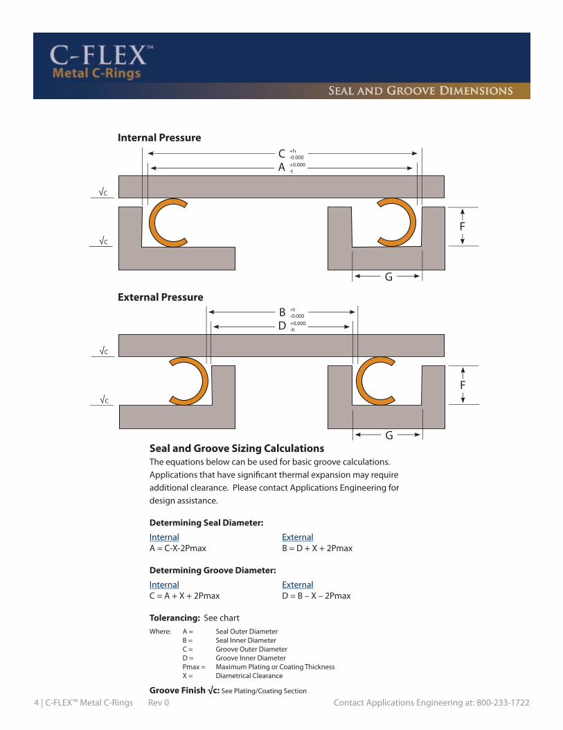
4 | C-FLEX™ Metal C-Rings Rev 0 Contact Applications Engineering at: 800-233-1722
Internal Pressure
C
External Pressure
A
+h-0.000+0.000-t
G
F
BD
+t-0.000+0.000-h
G
F
Seal and Groove Sizing CalculationsThe equations below can be used for basic groove calculations. Applications that have signifi cant thermal expansion may require additional clearance. Please contact Applications Engineering for design assistance.
Determining Seal Diameter:
Internal ExternalA = C-X-2Pmax B = D + X + 2Pmax
Determining Groove Diameter:
Internal ExternalC = A + X + 2Pmax D = B – X – 2Pmax
Tolerancing: See chartWhere: A = Seal Outer Diameter B = Seal Inner Diameter C = Groove Outer Diameter D = Groove Inner Diameter Pmax = Maximum Plating or Coating Thickness X = Diametrical Clearance
Groove Finish √c: See Plating/Coating Section
Seal and Groove Dimensions
√C
√C
√C
√C

Contact Applications Engineering at: 800-233-1722 Rev 0 C-FLEX™ Metal C-Rings | 5
Seal and Groove Dimensions
FreeHeight
0.047
0.063
0.094
0.125
0.157
0.188
0.250
Seal Diameter Range
Seal and Groove Dimensions
SEAL
0.250 to 4.000
0.300 to 6.000
0.400 to 16.000
1.000 to 25.000
1.250 to 30.000
2.000 to 40.000
4.000 to 50.000
Diametrical Clearance
x
0.006
0.007
0.008
0.012
0.016
0.018
0.020
GrooveDepth
F
0.038 ±0.001
0.050 ±0.001
0.074 ±0.002
0.100 ±0.002
0.127 ±0.002
0.151 ±0.002
0.200 ±0.003
GrooveWidth (Min.)
G
0.055
0.075
0.105
0.135
0.170
0.200
0.260
GROOVE
Seal Diameter Range
Tolerances
0.250 to 0.999
1.000 to 1.999
2.000 to 2.999
3.000 to 3.999
4.000 to 4.999
5.000 to 6.999
7.000 to 9.999
10.000 to 14.999
15.000 to 19.999
20.000 +
Seal Tolerance
t
0.002
0.002
0.003
0.003
0.004
0.006
0.007
0.012
0.015
GrooveTolerance
h
0.001
0.002
0.003
0.003
0.004
0.006
0.007
0.012
0.015
Contact Applications Engineering
Shaped Seals
C-Flex™ seals can be made in a variety of shapes and sizes. Typical Internal and External pressure seals can be formed into racetrack, square, triangular and rectangular shapes. Contact Applications Engineering for more information regarding shaped seal capabili-ties.
Minimum Corner Radii for Shaped C-Flex™ Seals
Cross Section 0.063 0.094 0.125 0.157 0.188 0.250
Minimum Inner Radius 0.375 0.565 1.000 2.000 3.000 4.000
Dimensions in inches
Dimensions in inches
Dimensions in inches
NOTE: Contact Applications Engineering for additional sizes.

6 | C-FLEX™ Metal C-Rings Rev 0 Contact Applications Engineering at: 800-233-1722
CD
+0.000-h+h-0.000
F
16
10º
16
BA
± t
± t
CS
NOTES:1. PCI = Pounds force per circumferencial inch2. Axial load is an approximate value. Actual value will vary based on diameter, interferences, friction coeffi cients, fi nish, platings, lubrication, etc.3. Load values are for Alloy 718 at 70ºF
Axial Pressure Applications
Dimensions in inches
10º
Cavity Finish ≤ 16 RMS
CrossSection
CS
0.063
0.094
0.125
0.157
0.188
0.250
MaterialThickness
(Prior to Forming)
SEAL CAVITY DIMENSIONS
SealID
Range
0.375 to 1.249
1.250 to 2.500
0.375 to 1.249
1.250 to 2.500
0.500 to 1.249
1.250 to 3.000
0.500 to 1.249
1.250 to 3.000
0.750 to 2.499
2.500 to 8.000
0.750 to 2.499
2.500 to 8.000
2.000 to 5.999
6.000 to 10.000
2.000 to 5.999
6.000 to 10.000
3.000 to 5.999
6.000 to 10.000
4.000 to 6.499
6.500 to 10.000
0.008
0.008
0.010
0.010
0.010
0.010
0.015
0.015
0.015
0.015
0.020
0.020
0.015
0.015
0.025
0.025
0.020
0.020
0.025
0.025
0.050
0.050
0.050
0.050
0.075
0.075
0.075
0.075
0.100
0.100
0.100
0.100
0.125
0.125
0.125
0.125
0.150
0.150
0.200
0.200
110
110
130
130
80
80
190
190
165
165
210
210
240
240
360
360
280
280
360
360
SealTolerance
t
0.001
0.001
0.001
0.001
0.001
0.001
0.001
0.001
0.001
0.002
0.001
0.002
0.002
0.002
0.002
0.002
0.002
0.002
0.002
0.002
CavityODC
B - 0.003
B - 0.004
B - 0.003
B - 0.004
B - 0.003
B - 0.004
B - 0.003
B - 0.004
B - 0.003
B - 0.006
B - 0.003
B - 0.006
B - 0.006
B - 0.007
B - 0.006
B - 0.007
B - 0.007
B - 0.008
B - 0.008
B - 0.009
AxialLength(Max. Ref )
AxialLoadPCI
CavityIDD
A + 0.003
A + 0.004
A + 0.003
A + 0.004
A + 0.003
A + 0.004
A + 0.003
A + 0.004
A + 0.003
A + 0.006
A + 0.003
A + 0.006
A + 0.006
A + 0.007
A + 0.006
A + 0.007
A + 0.007
A + 0.008
A + 0.008
A + 0.009
CavityTolerance
h
0.001
0.001
0.001
0.001
0.001
0.001
0.001
0.001
0.001
0.002
0.001
0.002
0.002
0.002
0.002
0.002
0.002
0.002
0.002
0.002
CavityDepthF (Min)
0.075
0.075
0.075
0.075
0.105
0.105
0.105
0.105
0.135
0.135
0.135
0.135
0.170
0.170
0.170
0.170
0.200
0.200
0.260
0.260
Cavity OD/IDEccentricity
(Max.)
0.0005
0.0005
0.0005
0.0005
0.0010
0.0010
0.0010
0.0010
0.0010
0.0010
0.0010
0.0010
0.0015
0.0015
0.0015
0.0015
0.0015
0.0015
0.0015
0.0015

HELICOFLEX DATA SHEETTel: 800-233-1722 Fax: 803-783-4279
E-Mail: [email protected]
COMPANY: PHONE:
CONTACT: FAX:
ADDRESS: E-MAIL:
DATE:
APPLICATION: (please attach customer drawing / sketch)
Brief Description:
Annual quantities: RFQ Quantities:
Is This a New Design? ❏ Yes ❏ No Are Modifications Possible? ❏ Yes ❏ No
Drawing or Sketch Attached? ❏ Yes ❏ No What is the Seal Type? ❏ Shaped ❏ Circular
SERVICE CONDITIONS:
Media: Life Expectancy:
Working Temperature: Max/Proof Pressure: @ Temp. =
Working Pressure: Max Temperature: @ Pressure =
Helium: Std.cc/sec
Pressure Cycles: Flow Rate: cc/minute
Other:
FLANGE DETAILS: (Please Provide Drawing)
Radial: Axial: #Cycles:
Material: Thickness:
Size: # Rating: Face Surface Finish: (RMS)
Standard: Size:
Description: (Please Provide Drawing)
GROOVE DETAILS: (Please Provide Drawing)
Type (Rectangular, Dovetail, etc.):
Outer Diameter: Tolerance: Depth: Tolerance:
Inner Diameter: Tolerance: Finish (RMS) Type:
BOLTING DETAILS: (Please Provide Drawing)
Size: Type / Grade:
Number: Tapped / Through:
OTHER:
Pressure Direction: (Internal/External/Axial)
Temperature Cycles:
Target Sealing Level:
Amount of Flange Movment in Service: (Inches)
❏ Groove / Counter Bore:
❏ ANSI Raised Face
❏ Flange(s) with Clamping System: (ISO,KF, etc)
❏ Other:
Please list dimensions in Groove Details section
Finish Type: lathe (circular), endmill (multi-directional), other
Bolt Circle
Special coating / plating specification:
Special quality / inspection specifications:
Other:

8 | C-FLEX™ Metal C-Rings Rev 0 Contact Applications Engineering at: 800-233-1722
The technical data contained herein is by way of example and should not be relied on for any spe-cific application. Garlock Helicoflex will be pleased to provide specific technical data or specifica-tions with respect to any customer’s particular applications. Use of the technical data or specifica-tions contained herein without the express written approval of Garlock Helicoflex is at user’s risk and Garlock Helicoflex expressly disclaims responsibility for such use and the situations which may result therefrom. Garlock Helicoflex makes no warranty, express or implied, that utilization of the technol-ogy or products disclosed herein will not infringe any industrial or intellectual property rights of third parties. Garlock Helicoflex is constantly involved in engineering and development. Accordingly, Garlock Helicoflex reserves the right to modify, at any time, the technology and product specifica-tions contained herein. All technical data, specifications and other information contained herein is deemed to be the proprietary intellectual property of Garlock Helicoflex. No reproduction, copy or use thereof may be made without the express written consent of Garlock Helicoflex.

Contact Applications Engineering at: 800-233-1722 Rev 1 E-FLEXTM Metal E-rings | 1
E-FlexTM Metal E-rings are designed to have low load, high spring back performance for high pres-sure/temperature applications. In service, the E-FlexTM is pressure energized by the system which increases the contact stress and further minimizes leakage. The E-FlexTM geometry can be designed to meet the requirements for each unique applica-tion and can be manufactured in a wide range of sizes. Typical markets for E-Flex™ seals include Aerospace, Land Based Turbines, and Automotive.
Sealing Concept
The standard E-FlexTM design exhibits improved spring back and reduced load compared to C-Rings.
E-Flex™
The Super E-FlexTM is designed to have less stress during instal-lation. These seals typically have less load than the traditional E-Flex™ seals and have nearly 100% spring back at room tem-perature.
Super E-Flex™
These seals are designed with extra convolutions and special geometry for applications that require maximum spring back in service.
Multi-convolution
E-Flex™ Types

2 | E-FLEXTM Metal E-rings Rev 1 Contact Applications Engineering at: 800-233-1722
Material Selection StatusMaterial Temperature
Solution heat treat and precipitation harden per AMS5598
Solution heat treat and precipitation harden per AMS5596
Solution heat treat, stabilize and precipitation harden per AMS5544
T < 1,100°F
T < 1,200°F
T < 1,350°F
Optional
Standard
Optional
Alloy X750
Alloy 718
Waspaloy
Heat Treatment
Coatings and Platings Type Description
An HVOC tribaloy coating ideal for applications exhibit-ing high wear patterns.
Not recommended for most applications. The E-Flex seal does not generate enough load to plastically deform the silver plating.Please contact Applications Engineering for special or custom coating requests.
TribologicalCoating
Silver Plating
Custom
NOTE: Actual spring back and load will vary based on material, geometry, and wall thickness. Please check characteristic chart for specific information.
E-Flex™ Characteristic Curve
Load
Deflection
Y2
PermanentDeformation
Useful Elastic RecoveryTotal Springback
e2
Load at OptimumCompression
OptimumCompression
Performance Data

Contact Applications Engineering at: 800-233-1722 Rev 1 E-FLEXTM Metal E-rings | 3
E-Flex™ Characteristics For Alloy 718 Material At 70ºF
NOTES: 1. PCI = Pounds force per circumferential inch2. Seating load (Y
2) is an approximation and may vary based on groove clearance, seal diameter,
tolerance and coating thickness. It does not allow for system pressure requirements and should be verified for each application and seal size. 3. The customer must verify that system bolts and flanges can generate the required seating load without warping or distorting.4. The customer must test and verify that the seal design meets customer designated performance requirements.
Other materials: Please contact Applications Engineering.Anti-Wear Coatings: Please contact Applications Engineering.
Performance Data
Dimensions in inches
E-Flex™Type
FreeHeight
MaterialThickness
SealDiameter
Seating Load(PCI)
Y2
InstallationSpringback
InstallationCompression
e2
E-FLEX™
0.075 0.006 0.6256.000
4228
0.0090.011
0.013
0.098 0.008 0.6258.000
10464
0.0130.014
0.021
0.102 0.010 0.6258.000
9256
0.0110.013
0.015
0.132 0.008 1.25024.000
3216
0.0130.014
0.014
0.132 0.015 1.25024.000
5028
0.0130.014
0.014
0.218 0.015 3.37540.000
9378
0.0260.031
0.037
0.243 0.010 6.00040.000
1211
0.0720.073
0.073
0.295 0.020 6.00060.000
8369
0.0460.047
0.048
0.375 0.020 8.00060.000
5544
0.0620.062
0.062
SuperE-FLEX™
0.108 0.0095 0.95040.000
3828
0.0150.021
0.021
0.140 0.010 1.75040.000
2414
0.0220.022
0.022
0.140 0.012 1.75040.000
4124
0.0210.022
0.022
Multiple Convolution
E-FLEX™
0.209 0.007 25.000 30 0.040 0.048
0.230 0.008 25.000 30 0.065 0.065
0.243 0.010 25.000 46 0.046 0.057
0.263 0.006 25.000 29 0.062 0.068
0.286 0.010 25.000 25 0.061 0.061
0.300 0.010 25.000 55 0.041 0.055

4 | E-FLEXTM Metal E-rings Rev 1 Contact Applications Engineering at: 800-233-1722
Seal and Groove Sizing CalcuationsThe equations below can be used for basic groove calculations. Applications that have signifi cant thermal expansion may require additional clearance. Please contact Applications Engineering for design assistance.
Determining Seal Diameter:
Internal ExternalA = C-X-2Pmax B = D + X + 2Pmax
Determining Groove Diameter:
Internal ExternalC = A + X + 2Pmax D = B – X – 2Pmax
Tolerancing: See chart
Where: A = Seal Outer Diameter B = Seal Inner Diameter C = Groove Outer Diameter D = Groove Inner Diameter Pmax = Maximum Plating or Coating Thickness x = Diametrical clearance
Seal and Groove Dimensions
Internal Pressure
C
External Pressure
A
+h-0.000+0.000-t
G
F
BD
+t-0.000+0.000-h
G
F
√ C
√C
√C
√C32
32
32
32

Contact Applications Engineering at: 800-233-1722 Rev 1 E-FLEXTM Metal E-rings | 5
NOTE: Contact Applications Engineering for additional sizes.
Seal and Groove Dimensions
Dimensions in inches
Tolerances
Dimensions in inches
SEAL GROOVE DIMENSIONS
FreeHeight
MaterialThickness
(Prior to Forming)
Radial Width(Max. Ref.)
Internal A Diameter
Range
External B Diameter
Range
DiametricalClearance
x
GrooveDepth
F
Groove Width(Min) G
Int. Press. Ext. Press.
E-FLEX™
0.075 0.006 0.066 1.360 to 6.000 1.200 to 6.000 0.003 0.062 ± 0.001 0.090 0.090
0.098 0.008 0.083 2.000 to 10.000 1.200 to 10.000 0.003 0.077 ± 0.002 0.110 0.110
0.102 0.010 0.091 2.000 to 10.000 1.200 to 10.000 0.003 0.087 ± 0.001 0.115 0.115
0.132 0.008 0.120 1.360 to 13.000 2.500 to 13.000 0.003 0.118 ± 0.002 0.145 0.145
0.132 0.015 0.120 1.360 to 13.000 2.500 to 13.000 0.003 0.118 ± 0.002 0.145 0.145
0.218 0.015 0.190 2.600 to 13.000 2.600 to 13.000 0.005 0.181 ± 0.002 0.210 0.220
0.243 0.010 0.260 6.000 to 40.000 6.000 to 40.000 0.005 0.170 ± 0.003 0.300 0.320
0.295 0.020 0.266 6.000 to 60.000 6.000 to 60.000 0.005 0.247 ± 0.003 0.315 0.335
0.375 0.020 0.340 8.000 to 60.000 8.000 to 60.000 0.005 0.313 ± 0.003 0.405 0.425
SuperE-FLEX™
0.108 0.0095 0.145 2.000 to 13.000 2.500 to 13.000 0.003 0.087 ± 0.002 0.170 0.180
0.140 0.010 0.194 2.500 to 13.000 2.500 to 13.000 0.005 0.118 ± 0.002 0.220 0.250
0.140 0.012 0.194 2.500 to 13.000 2.500 to 13.000 0.005 0.118 ± 0.002 0.220 0.250
Multiple Convolution
E-FLEX™
0.209 0.007 0.116 10.000 to 40.000 10.000 to 40.000 0.003 0.199 / 0.166 0.180 0.180
0.230 0.008 0.184 10.000 to 40.000 10.000 to 40.000 0.003 0.210 / 0.170 0.255 0.255
0.243 0.010 0.150 10.000 to 60.000 10.000 to 60.000 0.003 0.231 / 0.191 0.220 0.220
0.263 0.006 0.150 10.000 to 40.000 10.000 to 40.000 0.003 0.248 / 0.200 0.220 0.220
0.286 0.010 0.200 10.000 to 40.000 10.000 to 40.000 0.003 0.270 / 0.230 0.270 0.270
0.300 0.010 0.150 10.000 to 60.000 10.000 to 60.000 0.003 0.285 / 0.245 0.220 0.220
E-FLEX™ Super E-FLEX™ Multiple Convolution E-FLEX™
SealDiameter
Range
GrooveTolerance
"h"
SealTolerance
"t"
GrooveTolerance
"h"
SealTolerance
"t"
GrooveTolerance
"h"
SealTolerance
"t"
1.000 to 1.999 0.002 0.003 0.002 0.004 - -
2.000 to 2.999 0.002 0.004 0.003 0.006 - -
3.000 to 3.999 0.003 0.005 0.004 0.008 - -
4.000 to 4.999 0.003 0.006 0.004 0.008 - -
5.000 to 5.999 0.003 0.006 0.005 0.010 - -
6.000 to 6.999 0.004 0.007 0.006 0.012 - -
7.000 to 7.999 0.004 0.008 0.007 0.014 - -
8.000 to 8.999 0.005 0.009 0.008 0.016 - -
9.000 to 9.999 0.005 0.010 0.009 0.018 - -
10.000 to 10.99 0.005 0.010 0.010 0.020 0.005 0.010
11.000 to 11.999 0.006 0.011 0.010 0.020 0.006 0.011
12.000 to 12.999 0.006 0.012 0.010 0.020 0.006 0.012
13.000 to 13.999 0.007 0.013 0.010 0.020 0.007 0.013
14.000 + Contact Applications Engineering
E-Flex™Type

6 | E-FLEXTM Metal E-rings Rev 1 Contact Applications Engineering at: 800-233-1722
NOTE: Material: Alloy 718 per AMS 5596Heat Treatment: Solution heat treated and precipitation hardened per AMS 5596 in inert atmosphere.
AS 1895/7
Part Number AS1895/7Reference
Duct Size
SEAL DIMENSIONS
OD ID (Ref )Out of
Roundness of Outer Diameter
Free Height
E-800128 -100 AS1895/7 -100 1.00 1.2491.245 0.958 0.040
0.0200.1130.103
E-800128 -125 AS1895/7 -125 1.25 1.4991.495 1.208
0.0400.020
0.1130.103
E-800128 -150 AS1895/7 -150 1.50 1.7491.745 1.458
0.0400.020
0.1130.103
E-800128 -175 AS1895/7 -175 1.75 1.9991.995 1.708
0.0400.020
0.1130.103
E-800128 -200 AS1895/7 -200 2.00 2.2492.245 1.958
0.0400.020
0.1130.103
E-800128 -225 AS1895/7 -225 2.25 2.4992.493 2.208
0.0400.020
0.1130.103
E-800128 -250 AS1895/7 -250 2.50 2.7492.743 2.458
0.0400.020
0.1130.103
E-800128 -275 AS1895/7 -275 2.75 2.9992.993 2.708
0.0400.020
0.1130.103
E-800128 -300 AS1895/7 -300 3.00 3.2493.243 2.958
0.0400.020
0.1130.103
E-800128 -325 AS1895/7 -325 3.25 3.4993.491 3.208
0.0400.020
0.1130.103
E-800128 -350 AS1895/7 -350 3.50 3.7493.741 3.458
0.0500.030
0.1130.103
E-800128 -400 AS1895/7 -400 4.00 4.2494.241 3.958
0.0500.030
0.1130.103
E-800128 -450 AS1895/7 -450 4.50 4.7494.739 4.458
0.0500.030
0.1130.103
E-800128 -500 AS1895/7 -500 5.00 5.2495.239 4.958
0.0600.040
0.1130.103
E-800128 -550 AS1895/7 -550 5.50 5.7495.737 5.458
0.0600.040
0.1130.103
E-800128 -600 AS1895/7 -600 6.00 6.2496.237 5.958
0.0600.040
0.1130.103
E-800128 -650 AS1895/7 -650 6.50 6.7496.735 6.458
0.0650.045
0.1130.103
E-800128 -700 AS1895/7 -700 7.00 7.2497.235 6.958
0.0650.045
0.1130.103
E-800128 -750 AS1895/7 -750 7.50 7.7497.733 7.458
0.0650.045
0.1130.103

HELICOFLEX DATA SHEETTel: 800-233-1722 Fax: 803-783-4279
E-Mail: [email protected]
COMPANY: PHONE:
CONTACT: FAX:
ADDRESS: E-MAIL:
DATE:
APPLICATION: (please attach customer drawing / sketch)
Brief Description:
Annual quantities: RFQ Quantities:
Is This a New Design? ❏ Yes ❏ No Are Modifications Possible? ❏ Yes ❏ No
Drawing or Sketch Attached? ❏ Yes ❏ No What is the Seal Type? ❏ Shaped ❏ Circular
SERVICE CONDITIONS:
Media: Life Expectancy:
Working Temperature: Max/Proof Pressure: @ Temp. =
Working Pressure: Max Temperature: @ Pressure =
Helium: Std.cc/sec
Pressure Cycles: Flow Rate: cc/minute
Other:
FLANGE DETAILS: (Please Provide Drawing)
Radial: Axial: #Cycles:
Material: Thickness:
Size: # Rating: Face Surface Finish: (RMS)
Standard: Size:
Description: (Please Provide Drawing)
GROOVE DETAILS: (Please Provide Drawing)
Type (Rectangular, Dovetail, etc.):
Outer Diameter: Tolerance: Depth: Tolerance:
Inner Diameter: Tolerance: Finish (RMS) Type:
BOLTING DETAILS: (Please Provide Drawing)
Size: Type / Grade:
Number: Tapped / Through:
OTHER:
Pressure Direction: (Internal/External/Axial)
Temperature Cycles:
Target Sealing Level:
Amount of Flange Movment in Service: (Inches)
❏ Groove / Counter Bore:
❏ ANSI Raised Face
❏ Flange(s) with Clamping System: (ISO,KF, etc)
❏ Other:
Please list dimensions in Groove Details section
Finish Type: lathe (circular), endmill (multi-directional), other
Bolt Circle
Special coating / plating specification:
Special quality / inspection specifications:
Other:

8 | E-FLEXTM Metal E-rings Rev 1 Contact Applications Engineering at: 800-233-1722
The technical data contained herein is by way of example and should not be relied on for any spe-cific application. Garlock Helicoflex will be pleased to provide specific technical data or specifica-tions with respect to any customer’s particular applications. Use of the technical data or specifica-tions contained herein without the express written approval of Garlock Helicoflex is at user’s risk and Garlock Helicoflex expressly disclaims responsibility for such use and the situations which may result therefrom. Garlock Helicoflex makes no warranty, express or implied, that utilization of the technol-ogy or products disclosed herein will not infringe any industrial or intellectual property rights of third parties. Garlock Helicoflex is constantly involved in engineering and development. Accordingly, Garlock Helicoflex reserves the right to modify, at any time, the technology and product specifica-tions contained herein. All technical data, specifications and other information contained herein is deemed to be the proprietary intellectual property of Garlock Helicoflex. No reproduction, copy or use thereof may be made without the express written consent of Garlock Helicoflex.

Contact Applications Engineering at: 800-233-1722 Rev 0 Nuclear Reactor Pressure Vessel Seals | 1
Garlock Helicoflex is the world’s leading manu-facturer of Nuclear Reactor Pressure Vessel (RPV) Closure Head Seals. In addition, Garlock Helicoflex sealing technology is used extensively as primary seals on spent fuel storage and transportation casks.
Sealing Concept
O-FLEX™ Metal O-RingsThe O-FlexTM is manufactured of Alloy 718 or Stainless Steel 304 tubing. Alloy 718 is the most common and preferred material because it offers optimum strength, spring back and resistance to radiation and corrosion. The base tubing is plated with pure (99.95%) silver. This combination of elastic core (tubing) with deformable plastic layer (silver) pro-vides durable sealing for traditional Nuclear Reactor Pressure Vessels.
HELICOFLEX® Spring Energized SealsThe Helicoflex® seal is a high performance, flexible, metal seal that has exceptional compression and elastic recovery properties. The Helicoflex seal is composed of a close-wound helical spring surrounded by two metal jackets. The spring is selected to have a specific compression resistance. During compression, the resulting specific pressure forc-es the jacket to yield and fill the flange imperfections while ensuring positive contact with the flange sealing faces. Each coil of the helical spring acts independently and allows the seal to conform to surface irregularities on the flange surface. This combination of elastic-ity and plasticity makes the Helicoflex seal the best choice for ageing reactors.
Base Tubing
Plating
NRPVO-FLEX™
Helical Spring
Inner Lining
NRPVHELICOFLEX®
Outer Jacket

2 | Nuclear Reactor Pressure Vessel Seals Rev 0 Contact Applications Engineering at: 800-233-1722
Typical Seal Applications
RPV Closure Head SealsThese seals are the primary seal for the reactor pressure vessel. Typically, the seals are used in tan-dem with an inner and outer seal for redundancy. The seals are positioned in the reactor pressure vessel head with clips and screws for easy installa-tion and assembly.
Control Rod Drive (CRD) SealsPTFE coated O-FlexTM seals for CRD mechanisms.
Spent Fuel CasksPrimary seals for casks used in the storage and transportation of spent fuel assemblies.
Other ApplicationsSteam TurbinesPrimary LoopValvesWaste Heat SystemsSteam Pressurizer
Reactor TypesBWR – All TypesPWR – All TypesGas CooledNavy Nuclear
QA System AssessmentISO 9001:2000Title 10 CFR 50 Appendix BANSI / ASME N45.2Favorable Audits by NUPIC MembersANSI / ASME NQA-1KTA 1401

Contact Applications Engineering at: 800-233-1722 Rev 0 Nuclear Reactor Pressure Vessel Seals | 3
General Services
• Global leader for more than 50 years in nuclear RPV seal design and manufacturing. References available.
• RPV seal design and manufacturing for most PWR Nuclear Power Plants (NPP) and all BWR NPPs worldwide and to major NSSS worldwide. References available.
• Spent fuel cask seal design to all major spent fuel (transportation and storage) casks manufacturers worldwide. References available.
• Individual RPV seal design and recommendations for newly built PWR and BWR units.
• Seal and retainer design improvements to meet today’s industries requirements of tight outage itineraries and ALARA requirements.
• Qualified and experienced on-site field services to evaluate the cause of numer- ous RPV seal problems, i.e. for RPV seal leakages, etc.
• Nuclear seal qualification services for new applications.
• Quality Assurance program based on the requirements of 10 CFR 50 Appendix B, ASME, N45.2, ASME Boiler and Pressure Vessel Codes V and IX, NUPIC audited.
• 3rd party evaluation available for on-site laser scan & repair of mating surfaces, reactor pressure vessel flange, and pressure vessel closure head grooves.
• NPP field staff training available, i.e. handling, installation, removal of RPV seals.
• Airfreight packaging and crating and airfreight arrangement for quick response transportation (airfreight capability limitation given by seal design).
Garlock Helicoflex Emergency Response
• Emergency response for outage. Spare RPV seals available on demand.
• 24/7 emergency service phone (803) 695-3553 (U.S.A.)
• 24 - 36 hour worldwide emergency site service available, on request.
RPV Closure Lid RPV O-Flex™ Seals with installation clips
(Pho
tos
cour
tesy
of A
REVA
)
General Services

4 | Nuclear Reactor Pressure Vessel Seals Rev 0 Contact Applications Engineering at: 800-233-1722
Nuclear RPV Closure Head Seals
Wall Thickness
Free Height
Recommended Diameter
Range
Seating Load(PCI)Y
2*
Total Springback
(Min.)
Installation Compression
e2
0.0300.0370.0450.0600.0640.0400.0500.0600.0800.0850.0500.0620.0750.1000.106
0.0090.0090.0090.0090.0090.0150.0150.0150.0150.0150.0170.0170.0170.0170.017
8%10%12%16%17%8%
10%12%16%17%8%
10%12%16%17%
Installation Compression
%
2500
2500
4000
0.375
0.500
0.625
0.038
0.050
0.063
40to
180
120to
>180
120to
>180
ALLOY 718 BASE TUBINGRPV O-FLEX™
NOTE: Recommended compression % for NRPV O-FLEX is 16%* PCI = Pounds force per Circumferential Inch
Wall Thickness
Free Height
Recommended Diameter
Range
Seating Load(PCI)Y2*
Total Springback
(Min.)
Installation Compression
e2
0.052 0.01710%
Installation Compression
%
40000.520 N/A40to
>180
HIGH TEMPERATURE ALLOY SPRINGRPV Helicoflex: HN200
Dimensions in inches
Dimensions in inches

Contact Applications Engineering at: 800-233-1722 Rev 0 Nuclear Reactor Pressure Vessel Seals | 5
Clip Assemblies
RPV Closure Head Seals are typically held in the pressure vessel head with specially designed clips. Garlock Helicoflex recommends a clip be located at a minimum every 30” of seal circumference. This will ensure that the seal is securely held in place.
Type IThis clip can only be used with the traditional O-Flex RPV seal. This clip is designed to penetrate either a slot (most common) or a hole in ID of the O-FlexTM.
WallThickness
FreeHeight
SlotLength
S
SlotWidth
T
HoleDiameter
D
0.375 0.038 0.281 0.125 0.0700.500 0.050 0.375 0.205 0.0930.625 0.063 0.438 0.256 0.125
Type I Clip (O-FLEX Only)
NOTE: Type I clip can be used with a slot or hole (depending on ring design)
Number of Slots
O-FLEXDiameter
up to 72”72” to 144”
144” to 200”200” +
48
1216 or 24
Type IIThis style clip can be used with either the O-FlexTM or the Helicoflex® RPV seals. It is designed to hold the seal to the outer circumference of the groove without having to penetrate the ring through a slot. This makes seal installation easier since the seal does not require special alignment.
�
�
�
Dimensions in inches
Dimensions in inchesRetainer clip
Threaded Insert
Hex-socketscrew
Threaded Insert
Retainer clip
Hex-socketscrew

6 | Nuclear Reactor Pressure Vessel Seals Rev 0 Contact Applications Engineering at: 800-233-1722
Spent Fuel Storage Casks
Garlock Helicoflex metal seals offer the perfor-mance and flexibility to meet stringent spent fuel cask requirements. The Helicoflex seal in particular can be made in a wide variety of geometries and shapes to meet the demanding requirements of cask designers. Typical seal types are listed below. Please contact Applications Engineering to discuss your cask requirements.
Typical Cask Seal Locations:Cask Lid ClosuresFill PortsDrain Ports
Typical Configurations
HNDE290Leak check-
inert gas purge
HN208Raised face
flanges - ANSI B16.5
HN203Tongue & Groove
HN200Groove assembly
O-FLEX™ HELICOFLEX®
TN-40 Dry Storage Cask TN-32 Dry Storage Cask

Contact Applications Engineering at: 800-233-1722 Rev 0 Nuclear Reactor Pressure Vessel Seals | 7
Packing & Shipping
RPV Closure Head Seal PackagingGarlock Helicoflex offers two styles of protective packaging for RPV seals:
Regular “Casement Tubing”
Zipper Lock Tubing Packaging
This is a packaging upgrade that was developed using ALARA minded principles. This packaging is designed to be removed quickly and therefore reduce radiation exposure time during unpacking and installation.
Shipping
Individually wrapped seals are securely packaged in wooden crates. Special provisions are made for extra protection during overseas shipments. Typically, the crate is transport-ed by way of a specialized drop deck freight carrier. However, some crates may be custom designed for specialty ocean or air freight carriers.
RPV Seal
Polyethylene tubing
Polyethylene plastic pressure sensitive tape
Spiral wound polyurethane foam or polyethylene
RPV Seal Polyethylene SheetZippertubing
Spiral wound polyurethane foam or polyethylene
Anti-oxidation Paper

HELICOFLEX DATA SHEETTel: 800-233-1722 Fax: 803-783-4279
E-Mail: [email protected]
COMPANY: PHONE:
CONTACT: FAX:
ADDRESS: E-MAIL:
DATE:
APPLICATION: (please attach customer drawing / sketch)
Brief Description:
Annual quantities: RFQ Quantities:
Is This a New Design? ❏ Yes ❏ No Are Modifications Possible? ❏ Yes ❏ No
Drawing or Sketch Attached? ❏ Yes ❏ No What is the Seal Type? ❏ Shaped ❏ Circular
SERVICE CONDITIONS:
Media: Life Expectancy:
Working Temperature: Max/Proof Pressure: @ Temp. =
Working Pressure: Max Temperature: @ Pressure =
Helium: Std.cc/sec
Pressure Cycles: Flow Rate: cc/minute
Other:
FLANGE DETAILS: (Please Provide Drawing)
Radial: Axial: #Cycles:
Material: Thickness:
Size: # Rating: Face Surface Finish: (RMS)
Standard: Size:
Description: (Please Provide Drawing)
GROOVE DETAILS: (Please Provide Drawing)
Type (Rectangular, Dovetail, etc.):
Outer Diameter: Tolerance: Depth: Tolerance:
Inner Diameter: Tolerance: Finish (RMS) Type:
BOLTING DETAILS: (Please Provide Drawing)
Size: Type / Grade:
Number: Tapped / Through:
OTHER:
Pressure Direction: (Internal/External/Axial)
Temperature Cycles:
Target Sealing Level:
Amount of Flange Movment in Service: (Inches)
❏ Groove / Counter Bore:
❏ ANSI Raised Face
❏ Flange(s) with Clamping System: (ISO,KF, etc)
❏ Other:
Please list dimensions in Groove Details section
Finish Type: lathe (circular), endmill (multi-directional), other
Bolt Circle
Special coating / plating specification:
Special quality / inspection specifications:
Other:

Contact Applications Engineering at: 800-233-1722 Rev 0 Nuclear Reactor Pressure Vessel Seals | 9
The technical data contained herein is by way of example and should not be relied on for any spe-cific application. Garlock Helicoflex will be pleased to provide specific technical data or specifica-tions with respect to any customer’s particular applications. Use of the technical data or specifica-tions contained herein without the express written approval of Garlock Helicoflex is at user’s risk and Garlock Helicoflex expressly disclaims responsibility for such use and the situations which may result therefrom. Garlock Helicoflex makes no warranty, express or implied, that utilization of the technol-ogy or products disclosed herein will not infringe any industrial or intellectual property rights of third parties. Garlock Helicoflex is constantly involved in engineering and development. Accordingly, Garlock Helicoflex reserves the right to modify, at any time, the technology and product specifica-tions contained herein. All technical data, specifications and other information contained herein is deemed to be the proprietary intellectual property of Garlock Helicoflex. No reproduction, copy or use thereof may be made without the express written consent of Garlock Helicoflex.


Contact Applications Engineering at: 800-233-1722 Rev 0 Quick Disconnect Systems | 1
The Quick Disconnect System (QDS®) is designed to be assembled and disassembled quickly while offering space saving features. A typical QDS® requires less space than a traditional bolted assem-bly and can be easier to install, especially in tight locations where access to bolts and screws may be difficult. This feature is especially beneficial in radioactive environments where personnel expo-sure is an issue. The QDS® is available for both standard ISO-KF sizes and similar custom sizes for low and medium pressure applications.
Sealing Concept
QDS® Segmented Clamp
Integrated Centering Ring
Conical Flange
Helicoflex® Spring Energized Seal
Quick Disconnect System (Section View)

2 | Quick Disconnect Systems Rev 0 Contact Applications Engineering at: 800-233-1722
Pressure Limits x Nominal Diameter (70ºF)
7250
5800
4350
2900
1450
Pres
sure
(psi
)
1” 2” 3” 4” 5” 6”
Nominal Diameter
Class 1000
Class 500
Class 300150
Pressure Limits x Operating Temperature
7250
5800
4350
2900
1450
Pres
sure
(psi
)
750
Temperature (ºF)
Class 1000
Class 500
Class 300Class 150
570390210
* Reference only. Must be adjusted for nominal diameter.
Performance Data
NOTE: Hydraulic Pressure

Contact Applications Engineering at: 800-233-1722 Rev 0 Quick Disconnect Systems | 3
JacketMaterial
Class1000
QDS® Seal-Clamp Compatibility
Class500
Helicoflex®HL290P
Delta®HLV290P
OOOOO
OOOOO
OOOOO
OOOOO
AluminumSilver
CopperNickel
Stainless Steel
AluminumSilver
CopperNickel
Stainless Steel
Class300
OOXXX
OOXXX
Class150
OXXXX
OXXXX
Example:300KF55 1.5” Sch 10, shortClass 300Type KFFlange OD = 55mmPipe OD = 1.5”Pipe Schedule = 10Stub Length = Short (1.181”)
Blind Flanges:Blind Flanges may be specified by placing a “T” in front of the Reference Number
Example: T300KF55
* The class type is based on load capability expressed in N/mm and is NOT related to the pound ratings for ANSI B16.5 flanges.
Configurations
Clamps
Flanges
300 KF 55 1-½ Sch 10 ShortClass*
150300500
Flange TypeKF
Class 300/500
LStandard ISO
Class 150
Flange OD(mm)
Pipe/Tube OD(Class 300/500)
Reference Number Weld Stub Description
Pipe Schedule Tube thickness(Class 300/500)
Stub Length(Class 300/500)
300 A 55 NMClass*
150300500
Link Size Flange OD(mm)
Non-Magnetic(Optional)
This is a special option for applications that
require reduced magnetic permeability
Reference Number

4 | Quick Disconnect Systems Rev 0 Contact Applications Engineering at: 800-233-1722
Clamps: ISO KF
��
��
�
Light: Class 150
PartNumber
ISO KFNominalDiameter
Dein mm
maxpressure
psi bars
10/1620/2532/40
50
Diin mm
rin mm
ein mm
maxtorque
in.lb Nm
150 L 30150 L 40150 L 55150 L 75
2.2842.7953.3464.016
587185
102
0.8271.1811.7722.559
21304565
2.4022.2842.5592.796
61586571
0.9060.9060.9060.906
23232323
29017414573
2012105
35.062.080.089.0
479
10
NOTE: ISO nominal diameter is sometimes denoted as NW or QF
Heavy: Class 300
Material:- Aluminum links - Non-magnetic side-plates- Non-magnetic stainless steel screws
Technical Data:- Clamping load: 150 N/mm (860 lb/in)- Temperature: 392ºF (200ºC) max.The selection is made according to the ISO Nominal Diameter reference
CLAMP DIMENSIONS
PartNumber
ISO KFNominalDiameter
Dein mm
maxpressure
psi bars
10/1620/2532/40
50
Diin mm
rin mm
ein mm
maxtorque
in.lb Nm
300 L 30300 L 40300 L 55300 L 75
2.3622.7563.3073.937
607084
100
0.7871.1811.7722.559
20304565
2.1652.2842.4412.756
55586270
1.2601.2601.2601.260
32323232
870580580290
60404020
5389
124159
6101418
Material:- Stainless Steel links - Stainless Steel side-plates- Steel screw (stainless steel on request)
Technical Data:- Clamping load: 300 N/mm (1715 lb/in)- Temperature: 572ºF (300ºC) max.
CLAMP DIMENSIONS
�
ISO KF Standard sizes

Contact Applications Engineering at: 800-233-1722 Rev 0 Quick Disconnect Systems | 5
�������������
�������������
�
�
�
�
�
���
Flanges: ISO KF
ISO KFNominalDiameter
Din mm
X-longin mm
10162025324050
din mm
Gin mm
X-shortin mm
Flangeref. number
0.5510.7800.9841.1021.4961.7322.244
1419.82528384457
0.3940.6300.8270.9451.2601.5751.969
10162124324050
0.4800.6770.8741.0321.3461.6222.055
12.217.222.226.234.241.252.2
0.7870.7870.9840.9841.1811.1811.181
20202525303030
1.9691.9691.9691.9692.3622.3622.362
50505050606060
150 KF 30 ND 10150 KF 30 ND 16150 KF 40 ND 20150 KF 40 ND 25150 KF 55 ND 32150 KF 55 ND 40150 KF 75 ND 50
NOTE: Flange class 150 NF E 29-724/ISO 2861
FLANGE DIMENSIONS
Ain mm
1.1811.1811.5751.5752.1652.1652.953
30304040555575
Seals: ISO KF���
��
��������������� ���������������
ISO KFNominalDiameter
ØBin mm
10/1620/2532/40
50
Seal Type
1.1851.5792.1692.957
30.140.155.175.1
HL290P-4.8AI ND 16HL290P-4.8AI ND 25HL290P-4.8AI ND 40HL290P-4.8AI ND 50
Other jacket materials available upon request.
SEAL DIMENSIONS - ALUMINUM JACKET
ØDjin mm
0.8661.2681.8782.449
22.032.247.762.2
ISO KF Standard sizes
Standard ISO KF Flange per ISO 2861
Helicoflex Spring Energized SealType: HL290P

6 | Quick Disconnect Systems Rev 0 Contact Applications Engineering at: 800-233-1722
Clamps: Class 300
��
��
�
TubeOD (Max)
in mmClamp
ReferenceDe
in mm
Pressure (Max)
psi
300 A 30300 A 40300 A 55300 A 75300 B 92
300 B 114300 B 134300 C 167300 C 201300 C 252300 D 304300 D 356300 D 387300 D 438
Diin mm
rin mm
ein mm
Torque(Max)ft.lb
2.3622.7563.3073.9375.5126.2997.0879.055
10.63012.59814.96117.08718.11020.079
607084
100140160180230270320380434460510
0.7871.1811.7722.5593.1504.0164.8036.0247.3629.370
11.26013.30714.52816.535
2030456580
102122153187238286338369420
2.1652.2832.4412.7564.1344.5284.9216.1426.8907.6779.055
10.23610.82711.811
55586270
105115125156175195230260275300
1.2601.2601.2601.2601.6141.6141.6142.0872.0872.0872.7562.7562.7562.756
3232323241414153535370707070
87058058029029026123223220317417414511658
47
1013373737898989
133133133133
Material:- Stainless Steel links - Stainless Steel side-plates- Steel screw (stainless steel on request)
Technical Data:- Clamping load: 300 N/mm (1715 lb/in)- Temperature: 572ºF (300ºC) max.
Clamp Dimensions
�
0.7091.1021.6932.4412.9923.7804.5675.7487.0879.055
10.94512.99214.17316.142
182843627696
116146180230278330360410
Class 300 Assemblies

Contact Applications Engineering at: 800-233-1722 Rev 0 Quick Disconnect Systems | 7
ClampReference
Ain mm
FlangeReference
D1in mm
ein mm
Flange Dimensions
Flanges: Class 300
Seals: Class 300���
��
� �
ClampReference
ØBin mm
Seal Reference
ØDjin mm
Ein mm
Hin mm
Clamp Dimensions
Class 300 Assemblies
�
�
�
������������������
��
���
��
300 A 30300 A 40300 A 55300 A 75300 B 92
300 B 114300 B 134300 C 167300 C 201300 C 252300 D 304300 D 356300 D 387300 D 438
1.1811.5752.1652.9533.6224.4885.2766.5757.9139.921
11.96914.01615.23617.244
3040557592
114134167201252304356387438
0.7091.1021.6932.4803.0713.9374.7245.9067.2449.252
11.10213.15014.37016.378
1828436378
100120150184235282334365416
0.1570.1570.1570.1570.2480.2480.2480.3270.3270.3270.4450.4450.4450.445
4.04.04.04.06.36.36.38.38.38.3
11.311.311.311.3
300 KF 30300 KF 40300 KF 55300 KF 75300 KF 92
300 KF 114300 KF 134300 KF 167300 KF 201300 KF 252300 KF 304300 KF 356300 KF 387300 KF 438
300 A 30300 A 40300 A 55300 A 75300 B 92
300 B 114300 B 134300 C 167300 C 201300 C 252300 D 304300 D 356300 D 387300 D 438
1.1851.5792.1692.9573.6264.4925.2806.5797.9179.925
11.97214.02015.24017.248
30.140.155.175.192.1
114.1134.1167.1201.1252.1304.1356.1387.1438.1
0.8661.2681.8782.4493.2684.0554.7646.0637.2839.291
11.33913.26814.48816.496
22.032.247.762.283.0
103.0121.0154.0185.0236.0288.0337.0368.0419.0
0.1100.1100.1100.1100.1890.1890.1890.1890.1890.1890.1890.1890.1890.189
2.82.82.82.84.84.84.84.84.84.84.84.84.84.8
0.3150.3150.3150.3150.3540.3540.3540.4720.4720.4720.5510.5510.5510.551
8888999
12121214141414
HL290P - 2.8 x 30HL290P - 2.8 x 40HL290P - 2.8 x 55HL290P - 2.8 x 75HL290P - 4.8 x 92
HL290P - 4.8 x 114HL290P - 4.8 x 134HL290P - 4.8 x 167HL290P - 4.8 x 201HL290P - 4.8 x 252HL290P - 4.8 x 304HL290P - 4.8 x 356HL290P - 4.8 x 387HL290P - 4.8 x 438
Helicoflex Spring Energized SealType: HL290P
ND = Nominal Diameter

8 | Quick Disconnect Systems Rev 0 Contact Applications Engineering at: 800-233-1722
Clamps: Class 500
��
��
�
TubeOD (Max)
in mmClamp
ReferenceDe
in mm
Pressure(Max)
psiDi
in mmr
in mme
in mm
Torque(Max)ft.lb
Clamp Dimensions
�
Class 500 Assemblies
500 A 30500 A 40500 A 55500 B 75500 B 92
500 B 114500 C 134500 C 167500 D 201500 D 252500 D 304500 E 356500 E 387500 E 438
2.3622.7563.3074.8035.5126.2997.5599.055
11.18113.07114.96117.12618.70120.472
607084
122140160192230284332380435475520
0.7871.1811.7722.4803.1504.0164.7246.0247.2059.213
11.26013.15014.37016.378
2030456380
102120153183234286334365416
2.1652.2832.4414.1344.1344.5285.7096.1426.8908.3869.055
10.43311.02412.205
555862
105105115145156175213230265280310
1.2601.2601.2601.6141.6141.6142.0872.0872.7562.7562.7563.3073.3073.307
3232324141415353707070848484
4350290026102610203014501450116011601015870870580290
1313133737378989
133133133184184184
0.7091.1021.6932.4022.9923.7804.5285.6696.6938.661
10.78712.75614.01616.024
182843617696
115144170220274324356407
Material:- Stainless Steel links - Stainless Steel side-plates- Steel screw
Technical Data:- Clamping load: 500 N/mm (2855 lb/in)- Temperature: 662ºF (350ºC) max.

Contact Applications Engineering at: 800-233-1722 Rev 0 Quick Disconnect Systems | 9
Flanges: Class 500
Seals: Class 500���
��
� �
ClampReference
ØBin mm
Seal Reference
ØDjin mm
Ein mm
Hin mm
Clamp Dimensions
Class 500 Assemblies
�
�
�
��
��� �
�
������������������
��
500 A 30500 A 40500 A 55500 B 75500 B 92
500 B 114500 C 134500 C 167500 D 201500 D 252500 D 304500 E 356500 E 387500 E 438
1.1851.5792.1692.9573.6264.4925.2806.5797.9179.925
11.97214.02015.24017.248
30.140.155.175.192.1
114.1134.1167.1201.1252.1304.1356.1387.1438.1
0.8661.2681.8782.4493.2684.0554.7646.0637.2839.291
11.33913.26814.48816.496
22.032.247.762.283.0
103.0121.0154.0185.0236.0288.0337.0368.0419.0
0.1100.1100.1100.1260.1260.1260.1260.1260.1260.1260.1260.1260.1260.126
2.82.82.83.23.23.23.23.23.23.23.23.23.23.2
0.3150.3150.3150.3540.3540.3540.4720.4720.5510.5510.5510.6300.6300.630
888999
1212141414161616
HL290P - 2.8 x 30HL290P - 2.8 x 40HL290P - 2.8 x 55HL290P - 3.2 x 75HL290P - 3.2 x 92
HL290P - 3.2 x 114HL290P - 3.2 x 134HL290P - 3.2 x 167HL290P - 3.2 x 201HL290P - 3.2 x 252HL290P - 3.2 x 304HL290P - 3.2 x 356HL290P - 3.2 x 387HL290P - 3.2 x 438
ClampReference
Bin mm
Flange Reference
D1in mm
gin mm
ein mm
Clamp DimensionsA
in mm
500 A 30500 A 40500 A 55500 B 75500 B 92
500 B 114500 C 134500 C 167500 D 201500 D 252500 D 304500 E 356500 E 387500 E 438
0.9921.3942.0042.5753.4134.2014.9096.2097.4299.437
11.48413.41314.63416.642
25.235.450.965.486.7
106.7124.7157.7188.7239.7291.7340.7371.7422.7
0.7091.1021.6932.4023.0713.9374.6465.9067.0879.094
11.10212.99214.21316.220
1828436178
100118150180231282330361412
0.0310.0310.0310.0350.0350.0350.0350.0350.0350.0350.0350.0350.0350.035
0.80.80.80.90.90.90.90.90.90.90.90.90.90.9
0.1890.1890.1890.3110.3110.3110.3900.3900.5080.5080.5080.6650.6650.665
4.84.84..87.97.97.99.99.9
12.912.912.916.916.916.9
500 KF 30500 KF 40500 KF 55500 KF 75500 KF 92
500 KF 114500 KF 134500 KF 167500 KF 201 500 KF 252500 KF 304500 KF 356500 KF 387500 KF 438
1.1811.5752.1652.9533.6224.4885.2766.5757.9139.921
11.96914.01615.23617.244
3040557592
114134167201252304356387438

10 | Quick Disconnect Systems Rev 0 Contact Applications Engineering at: 800-233-1722
Standard Schedule Pipe Sizes
PipeOD (Max)
in mm
NomPipe
Size (in)Thickness
in mmID
in mmThicknessin mm
IDin mm
Schedule 5S Schedule 10S
Standard Schedule Pipe Sizes
PipeOD (Max)
in mm
NomPipe
Size (in)Thickness
in mmID
in mmThicknessin mm
IDin mm
Schedule 40S Schedule 80S
1/81/41/23/4
11-1/2
22-1/2
34568
10121416
0.0650.0650.0650.0650.0650.0830.0830.0830.1090.1090.1090.1340.1560.1560.165
1.651.651.651.651.652.102.102.102.772.772.773.403.963.964.19
0.7100.9181.1851.7702.2452.7103.3354.3355.4636.4078.407
10.48212.43813.68815.670
18.0423.3130.1044.9657.0368.8384.70
110.10138.76162.74213.54266.25315.93347.68398.02
0.0490.0650.0830.0830.1090.1090.1090.1200.1200.1200.1340.1340.1480.1650.1800.1880.188
1.241.652.112.112.772.772.773.053.053.053.403.403.764.194.574.784.78
0.3070.4100.6740.8841.0971.6822.1572.6353.2604.2605.2956.3578.329
10.42012.39013.62415.624
7.8110.4217.1222.4527.8642.7254.7966.9382.80
108.20134.50161.48211.56264.67314.71346.04396.84
0.4050.5400.8401.0501.3151.9002.3752.8753.5004.5005.5636.6258.625
10.75012.75014.00016.000
10.2913.7221.3426.6733.4048.2660.3373.0388.90
114.30141.30168.28219.08273.05323.85355.60406.40
1/81/41/23/4
11-1/2
22-1/2
34568
10121416
0.0680.0880.1090.1130.1330.1450.1540.2030.2160.2370.2580.2800.3220.3650.3750.3750.375
1.732.242.772.873.383.683.915.165.496.026.557.118.189.279.529.529.52
6.839.24
15.8020.9326.6440.9052.5162.7177.92
102.26128.20154.06202.72254.51304.81336.56387.36
0.0950.1190.1470.1540.1790.2000.2180.2760.3000.3370.3760.4320.5000.5000.5000.5000.500
2.413.023.733.914.555.085.547.017.628.569.53
10.9712.7012.7012.7012.7012.70
0.2150.3020.5460.7420.9571.5001.9392.3232.9003.8264.8135.7617.6259.750
11.75013.00415.000
5.477.68
13.8818.8524.3038.1049.2559.0173.6697.18
122.24146.34193.68247.65298.45330.30381.00
0.4050.5400.8401.0501.3151.9002.3752.8753.5004.5005.5636.6258.625
10.75012.75014.00016.000
10.2913.7221.3426.6733.4048.2660.3373.0388.90
114.30141.30168.28219.08273.05323.85355.60406.40
0.2690.3640.6220.8241.0491.6102.0672.4693.0684.0265.0476.0657.981
10.02012.00013.25015.250

Contact Applications Engineering at: 800-233-1722 Rev 0 Quick Disconnect Systems | 11
ISO Standard Tubing
TubeOD
in mmThickness
in mmID
in mmThicknessin mm
IDin mm
Light Medium
Thicknessin mm
IDin mm
Heavy
Weld Stub Lengths
shortin mm
longin mm
extra longin mm
Stub Length (X)
SuffixClass
FlangeReference
0.0390.0390.0390.0390.0390.0390.0390.0390.0390.0390.0590.0590.063
1.001.001.001.001.001.001.001.001.001.001.501.501.60
0.1570.2360.3150.3940.4720.5510.7090.9061.0241.4171.6342.1262.870
4.006.008.00
10.0012.0014.0018.0023.0026.0036.0041.5054.0072.90
0.0590.0590.0590.0590.0590.0590.0630.0790.0790.091
1.501.501.501.501.501.501.602.002.002.30
0.3540.4330.6690.8660.8660.9841.3701.5942.0872.815
9.0011.0017.0022.0022.0025.0034.8040.5053.0071.50
0.2360.3150.3940.4720.5510.6300.7870.9841.1021.4961.7522.2442.996
6.008.00
10.0012.0014.0016.0020.0025.0028.0038.0044.5057.0076.10
0.0790.0790.0790.0790.0790.0790.1020.1020.114
2.002.002.002.002.002.002.602.602.90
0.3940.4720.6300.8270.9451.3391.5472.0392.768
10.0012.0016.0021.0024.0034.0039.3051.8070.30
0.7870.9841.1811.1811.1811.7721.9691.9691.9691.9691.9692.3622.3622.362
2025303030455050505050606060
1.9691.9692.3622.3622.3623.1503.5433.5433.9373.9373.9374.7244.7244.724
5050606060809090
100100100120120120
3.9373.9374.7244.7244.7246.2997.8747.8747.8747.8747.8749.4499.4499.449
100100120120120160200200200200200240240240
500500500500500500500500500500500500500500
KF 30KF 40KF 55KF 75KF 92
KF 114KF 134KF 167KF 201KF 252KF 304KF 356KF 387KF 438
300300300300300300300300300300300300300300
150150150150N/AN/AN/AN/AN/AN/AN/AN/AN/AN/A
Standard Schedule Pipe Sizes

12 | Quick Disconnect Systems Rev 0 Contact Applications Engineering at: 800-233-1722
QDS Class 1000The Class 1000 series is a heavy duty clamp and flange assembly designed for medium to high pressure. The flange and seal assembly can be modified to accept a variety of seal configurations. Please contact Applications Engineering for more information.
Remote HandlingThe QDS® clamp and seal can be fitted with special handling features such as custom cross bolts and seal tabs for easy installation and removal with remote handling equip-ment. These custom QDS® assemblies are ideal for radioactive environments where personnel exposure must be reduced or eliminated. Please contact Applications Engineering for more information.

QDS DATA SHEETTel: 800-233-1722 Fax: 803-783-4279
E-Mail: [email protected]
COMPANY: PHONE:
CONTACT: FAX:
ADDRESS: E-MAIL:
DATE:
APPLICATION
Brief Description:
Is This a New Design? ❏ Yes ❏ No Are Modifications Possible? ❏ Yes ❏ No
Drawing or Sketch Attached? ❏ Yes ❏ No
SERVICE CONDITIONS
Working Pressure: Temp/Pressure Cycles:
Maximum Pressure: Media:
Working Temperature: Required Sealing Level:
Maximum Temperature: Life Expectancy:
❏ Non-Magnetic Required
FLANGE DETAILS
❏ Remote Handling Required (Radiation?)
❏ Garlock to Design (If flange design exists, then fill out “Standard” or “Special” Section below as appropriate).
❏ Standard Size (ie. ND, KF, DN, ISO, etc): ______________ Face Surface Finish: _______________ (RMS)
Flange Material ___________________________________
❏ Special If not standard, provide drawing or dimensions in picture below.
Flange Material = ___________
Ø D = ___________
Ø A = ___________
Flange Thickness h = ___________
Flange Angle = ___________
Clamp Width/Thickness = ___________
Clamp Clearance De = ___________
Bolt Clearance r = ___________
Flange Stub Length = ___________
PIPE DETAILS
Size: ____________________________________________ Material Grade: ___________________________________________
Thickness: (Schedule / ISO Size may be provided instead) ___________________________________________
COMMENTS / NOTES
��
��
�
Flange Ø A
Pipe Ø D
h

14 | Quick Disconnect Systems Rev 0 Contact Applications Engineering at: 800-233-1722
The technical data contained herein is by way of example and should not be relied on for any spe-cific application. Garlock Helicoflex will be pleased to provide specific technical data or specifica-tions with respect to any customer’s particular applications. Use of the technical data or specifica-tions contained herein without the express written approval of Garlock Helicoflex is at user’s risk and Garlock Helicoflex expressly disclaims responsibility for such use and the situations which may result therefrom. Garlock Helicoflex makes no warranty, express or implied, that utilization of the technol-ogy or products disclosed herein will not infringe any industrial or intellectual property rights of third parties. Garlock Helicoflex is constantly involved in engineering and development. Accordingly, Garlock Helicoflex reserves the right to modify, at any time, the technology and product specifica-tions contained herein. All technical data, specifications and other information contained herein is deemed to be the proprietary intellectual property of Garlock Helicoflex. No reproduction, copy or use thereof may be made without the express written consent of Garlock Helicoflex.

Contact Applications Engineering at: 800-233-1722 Rev 0 Custom Seals | 1
Custom Products & Services
Garlock Helicofl ex off ers custom designed sealing solutions for diffi cult or extreme applications. Our design capabilities are supported with seal modeling, prototyping and testing services. Contact Applications Engineering for more information regarding these products and services.
Machined Seals
Machined seals are made from solid metal and are typically used in applications requiring a very small di-ameter. The seal geometry and material can be custom designed to meet most customer requirements.
U-Flex™
The U-Flex™ is a variation of the E-Flex™. It has very good spring back but does not have the compression range of most E-Flex™ seals. However, it may be a cost eff ective solution for applications requiring more spring back than a typical C-Flex™.
Custom Configurations
Most metal seals can be manufactured in various shapes and sizes. The Helicofl ex® Spring Energized Seal is particularly fl exible in design and function. Helicofl ex® seals can be designed and manufactured for remote handling, tandem sealing, quartz windows, radio frequency wave guides and many other custom applications.
Other Custom Products
Locking RingsBoss SealsDampening Rings

HELICOFLEX DATA SHEETTel: 800-233-1722 Fax: 803-783-4279
E-Mail: [email protected]
COMPANY: PHONE:
CONTACT: FAX:
ADDRESS: E-MAIL:
DATE:
APPLICATION: (please attach customer drawing / sketch)
Brief Description:
Annual quantities: RFQ Quantities:
Is This a New Design? ❏ Yes ❏ No Are Modifications Possible? ❏ Yes ❏ No
Drawing or Sketch Attached? ❏ Yes ❏ No What is the Seal Type? ❏ Shaped ❏ Circular
SERVICE CONDITIONS:
Media: Life Expectancy:
Working Temperature: Max/Proof Pressure: @ Temp. =
Working Pressure: Max Temperature: @ Pressure =
Helium: Std.cc/sec
Pressure Cycles: Flow Rate: cc/minute
Other:
FLANGE DETAILS: (Please Provide Drawing)
Radial: Axial: #Cycles:
Material: Thickness:
Size: # Rating: Face Surface Finish: (RMS)
Standard: Size:
Description: (Please Provide Drawing)
GROOVE DETAILS: (Please Provide Drawing)
Type (Rectangular, Dovetail, etc.):
Outer Diameter: Tolerance: Depth: Tolerance:
Inner Diameter: Tolerance: Finish (RMS) Type:
BOLTING DETAILS: (Please Provide Drawing)
Size: Type / Grade:
Number: Tapped / Through:
OTHER:
Pressure Direction: (Internal/External/Axial)
Temperature Cycles:
Target Sealing Level:
Amount of Flange Movment in Service: (Inches)
❏ Groove / Counter Bore:
❏ ANSI Raised Face
❏ Flange(s) with Clamping System: (ISO,KF, etc)
❏ Other:
Please list dimensions in Groove Details section
Finish Type: lathe (circular), endmill (multi-directional), other
Bolt Circle
Special coating / plating specification:
Special quality / inspection specifications:
Other:

Contact Applications Engineering at: 800-233-1722 Rev 0 Materials Information | 1
AMS Specifications and Heat Treatments
Common Material AMS Specifi cations
Material
AluminumNickel
St. SteelSt. SteelSt. SteelSt. SteelSt. Steel
AlloyAlloyAlloyAlloyAlloyAlloy
TitaniumWaspaloy
Seamless
--
5560-
5573-
5570-
45745580558155905582
--
--
5565---
5576---
5581----
Welded
1100201304
304L316
316L321
C276400600625718
X-750Grd 2
Grade
400155535513551155245507551055304544554055995596559849025544
Sheet / Strip
Tubing
Solution Heat Treat / Anneal Stainless Steel (300 series): Anneal at 2000ºF for 3 minutes Nickel: Anneal at 1325ºF for 90 minutes Alloy X-750: Solution heat treat/anneal per AMS 5598 Section 3.4 Alloy 718: Solution heat treat/anneal per AMS 5596 Section 3.4 Other materials: Contact Applications Engineering
Precipitation Harden / Age Stainless Steel (300 Series): N/A Nickel: N/A Alloy X-750: Precipitation harden per AMS 5598 per Section 3.5.2 Alloy 718: Precipitation harden per AMS 5596 Section 3.5.2 Other materials: Contact Applications Engineering
Special Heat Treatments NACE: Temper per NACE MR0175 for control of stress corrosion cracking Custom 2-stage stainless steel anneal (316L VIMVAR stainless steel) Aluminum anneal (Alloys 6061 and 2024)
Contact Applications Engineering for more information.
Heat Treatments

2 | Materials Information Rev 0 Contact Applications Engineering at: 800-233-1722
Stainless Steels
Grade
304
316
321
UNS Description
Nickel Alloys
Description
Chromium-Nickel austenitic alloy. Used for a wide vari-ety of home and commercial applications, this is one of the most familiar and most frequently used alloys in the stainless steel family.
Molybdenum-bearing austenitic stainless steel which is more resistant to general corrosion and pitting/crev-ice corrosion than the conventional chromium-nickel austenitic stainless steels. This alloy offers higher creep, stress-to-rupture and tensile strength at elevated tem-peratures.
A stabilized stainless steel which offers an excellent resistance to intergranular corrosion following exposure to temperature in the chromium carbide precipitation range from 800-1500°F (430-820°C).
S30400
S31600
S32100
Densitylb/in3
(g/cm3)
0.285(7.90)
0.290(8.03)
0.286(7.92)
Tensile Strength ksi (Mpa)
75 (515)
75 (515)
75 (515)
Yield Strength at 0.2% offset
ksi (MPa)
30 (205)
30 (205)
30 (205)
30 (205)
30 (205)
30 (205)
Elongation%
92 Rb
95 Rb
95 Rb
Hardness
Alloy 276
Alloy 400
Alloy 600
Alloy 625
Alloy 718
Alloy X-750
Waspaloy
A nickel-molybdenum-chromium-iron-tunsten alloy which is among the most corrosion resistant of alloys currently available. Alloy 276 alloy is widely used in the severest environments.
A ductile nickel-copper alloy with resistance to a variety of corrosive conditions.
A non-precipitation hardenable, high-strength nickel-chromium alloy. Service temperatures up to 1000ºF.
An austenitic nickel-base superalloy possessing excellent resistance to oxidation and corrosion over a broad range of corrosive conditions. It has outstanding strength and toughness at temperatures ranging from cryogenic to high temperature.
A precipitation hardenable, high-temperature nickel alloy that combines excellent corrosion resistance, high-strength and weldability. Resistant to post-weld cracking. Service temperatures up to 1200ºF.
A precipitation hardenable, high-strength and high-tem-perature nickel alloy. Service temperatures up to 1100ºF.
N10276
N04400
N06600
N06625
N07718
N07750
N07001
0.321 (8.89)
0.318 (8.80)
0.306 (8.47)
0.305 (8.44)
0.297 (8.23)
0.299 (8.28)
120(825)
80 (550)
95 (655)
135 (930)
195 (1345) (Heat
Treated)
175 (1207) (Heat
Treated)
60 (415)
40 (275)
45 (310)
70 (485)
170 (1170) (Heat
Treated)
115 (793) (Heat
Treated)
55
40
40
45
17 (Heat
Treated)
20 (Heat
Treated)
90 Rb
70 Rb
80 Rb
95 Rb
43 Rc (Heat
Treated)
35 Rc (Heat
Treated)
A precipitation hardenable nickel alloy with excellent high-temperature strength. Service temperatures up to 1350ºF.
0296 (8.19)
80 (550)
40 (275)
40 70 Rb
Material Properties

Contact Applications Engineering at: 800-233-1722 Rev 0 Materials Information | 3
OtherMaterials
Grade
Nickel 201
Aluminum (Alloy 1100)
Silver (99.99 pure)
Titanium
Tantalum
Copper
UNS Description
Description
Commercially pure wrought Nickel with similar proper-ties to Alloy 200 but with a lower carbon content to pre-vent embrittlement by intergranular carbon at elevated temperatures.
Commercially pure aluminum that contains a minimum of 99.0% aluminum. It has good formability and high resistance to corrosion.
Commercially pure silver is very ductile, malleable, and capable of a high degree of polish.
Densitylb/in3
(g/cm3)
0.321(8.89)
0.098(2.71)
0.379(10.491)
Tensile Strength ksi (Mpa)
58.6(403)
13(89.6)
20.3(140)
Yield Strength at 0.2% offset
ksi (MPa)
14.9(103)
5(34.5)
50
45
Elongation%
75-100 HB
23 HB
25 HV
Hardness
Commercially pure Titanium Grade 2 is the most com-monly used and widely available grade of unalloyed titanium. The grade combines excellent corrosion resis-tance and weldability with good strength, ductility and formability.
Superior resistance to all acids except hydrofluoric and hot sulfuric. Good for most aqueous salt solutions.
Good to excellent corrosion resistance. Excellent hot and cold workability.
0.163(4.51)
0.6(16.6)
0.323(8.94)
50(340)Min.
40(276)
33(227)
40(280)Min.
25(172)
11(76)
22
50
41
80 Rb
35 Rb
72 Rb
N02201
A91100
R50400
C11000
Typical room temperature mechanical properties.
The technical data contained herein is by way of example only and should not be relied on for any specific application.
Material Properties

4 | Materials Information Rev 0 Contact Applications Engineering at: 800-233-1722
The technical data contained herein is by way of example and should not be relied on for any spe-cific application. Garlock Helicoflex will be pleased to provide specific technical data or specifica-tions with respect to any customer’s particular applications. Use of the technical data or specifica-tions contained herein without the express written approval of Garlock Helicoflex is at user’s risk and Garlock Helicoflex expressly disclaims responsibility for such use and the situations which may result therefrom. Garlock Helicoflex makes no warranty, express or implied, that utilization of the technol-ogy or products disclosed herein will not infringe any industrial or intellectual property rights of third parties. Garlock Helicoflex is constantly involved in engineering and development. Accordingly, Garlock Helicoflex reserves the right to modify, at any time, the technology and product specifica-tions contained herein. All technical data, specifications and other information contained herein is deemed to be the proprietary intellectual property of Garlock Helicoflex. No reproduction, copy or use thereof may be made without the express written consent of Garlock Helicoflex.

Contact Applications Engineering at: 800-233-1722 Rev 1 Technical Information | 1
The performance of a resilient metal seal depends on two basic factors: elasticity and plasticity. The concept is similar to an elastomer seal such as Viton or Buna. The differ-ence is that the elastomer compound serves both functions where a metal seal must use two components: a substrate and a soft outer layer.
Performance of Resilient Metal Seals
ElasticityEach seal has a resilient metal substrate in the form of a spring (Helicoflex®), tubing (O-Flex™), or formed strip (E-Flex™, C-Flex™). This substrate serves to provide a specific load that is used to deform a soft outer layer. The substrate also has a certain amount of spring back that helps maintain constant contact force during service. This spring back is not necessarily designed to compensate for axial or radial flange separation. Instead, it ensures that the seal maintains enough contact force to properly seal a static joint in service.
PlasticityThe soft outer layer is usually a plating/coating or a wrapped jacket. This outer layer is designed to plastically deform based on the specific load generated by the substrate. As the soft outer layer is deformed, it flows into the flange/groove imperfections and creates a seal. The tightness of the seal will depend on the amount of specific load, the ductility of the outer layer and the groove surface finish. An ideal groove/flange finish has machin-ing marks that follow the circumference of the seal. Any radial marks or scratches may not be completely filled by the soft outer layer and could create a leak.
Resilient Metal Seals
Compression
Compression Specific Pressure
Elasticity Plasticity
These two functions ensure and maintain specific pressure in service.

2 | Technical Information Rev 1 Contact Applications Engineering at: 800-233-1722
A bolted joint is an assembly that relies on each component to work properly. The perfor-mance and success of the bolted joint depends on the quality and design of each of these components. There are three major components of every bolted joint:
1. Flanges (Flange design / Groove dimensions & finish)2. Bolts / Fasteners3. Seal / Gasket
The above components cannot be designed mutually exclusive of each other. They must be considered together as a system during the design process. If any part of the bolted joint assembly does not perform properly, the joint as a whole will not perform to expec-tations and may leak.
Bolted Joints
Bolt Load and Tightening TorqueWhen using bolts to fasten the sealing joint the bolts must be of suitable strength and quantity to compress the seal and withstand the maximum hydrostatic load. Additionally, the bolts and flanges must be robust enough to prevent warpage, distortion or separa-tion during service. All service factors must be considered such as thermal stresses, differ-ential expansion, external loads and vibration.
System Pressure
Seal Specific Pressure
Bolted Joints

Contact Applications Engineering at: 800-233-1722 Rev 1 Technical Information | 3
Bolted Joints
Bolt Load EstimatesThe following equations may be used to estimate required bolt loads.
NOTE: These estimates are off ered as guidelines only. There are many other factors that the fl ange designer must consider such as: thermal cycling, vibration, cyclic fatigue, fl ange thickness, fl ange rotation, bolt stress relaxation, additional bolt preload, externally applied loads, etc. The customer is responsible for the fl ange design and for ensuring that the fl anges, bolts and bolt loads are suffi cient for the application. Please refer to Section VIII of the ASME Boiler and Pressure Vessel Code for code requirements.
Total Bolt Load ≥ Seal Seating Load + Hydrostatic Load + Safety Factor
Seal Seating LoadTotal load required to compress the seal to optimal level. This information can be found for each seal type in the Performance Data sections of the catalog. It is referenced as Y
2 and is given in
pounds per circumferential inch (PCI).
Seal Seating Load = Seal Diameter x π x Y2
Hydrostatic Load
Load required to contain the system pressure.
Hydrostatic Load = Maximum system pressure x (π/4) x (Seal Diameter)2
Safety FactorThis is a customer determined safety factor and must consider: system temperature eff ects, tem-perature cycling/spikes, pressure cycling/spikes, vibration, etc.
NOTE: A more detailed calculation is available for the Helicofl ex spring energized seals. Please see the Helicofl ex Seal product section.
Example Calculation
Seal: O-Flex metal o-ring, Material = SS321OD = 4.000in, CS = .125in, wall thickness = .020inY
2 = 1142 lbs/in
Operating Conditions:Pressure: 500 psi, Temperature: 70 F
Seating Load = 4.000in x π x 1142lbs/in = 14351 lbsHydrostatic Load = 500 lbs/in2 x (π/4) x (4.000in)2 = 6283 lbs
Total Bolt Load Estimate ≥ 14351 lbs + 6283 lbs + customer safety factor
NOTE: each application should be reviewed to determine if additional bolt preload may be required for proper bolt stretch.

4 | Technical Information Rev 1 Contact Applications Engineering at: 800-233-1722
Tightening Torque and Bolt TensionThe following equation may be used to create a rough estimate of the required torque:
T = K x P x D
Where: T= tightening torque (in-lbs) K*= dynamic coeffi cient of friction (i.e. minimum = .15 (dry-zinc plated)) P= total bolt load / number of bolts (lbf ) D= nominal bolt diameter (in)
(* Also referred to as the “nut factor” in some texts.)
It must be understood that every bolted joint is unique and the tightening torque should be determined for each application through experimentation. A properly tightened bolt is one that is stretched, thus acting like a very rigid spring pulling the mating surfaces together. As the bolt is tightened it begins to stretch and goes into a state of tension. There are many factors that aff ect how much tension occurs when a given amount of tightening torque is applied. These factors in-clude bolt diameter, bolt grade (strength), and friction. Torque calculations can have signifi cant er-rors based on these factors, especially friction. Best practice indicates that bolts should be properly lubricated and hardened washers used under the head and nut.
Where possible, it is recommended the fastener elongation, or stretch, be measured directly to ensure proper tension or preload, in the fastener.
NOTE: These estimates are off ered as guidelines only. There are many other factors that the fl ange designer must consider such as: thermal cycling, vibration, cyclic fatigue, fl ange thickness, fl ange rotation, bolt stress relaxation, additional bolt preload, externally applied loads, etc. The customer is responsible for the fl ange design and for ensuring that the fl anges, bolts and bolt loads are suffi cient for the application. Please refer to Section VIII of the ASME Boiler and Pressure Vessel Code for code requirements.
Bolted Joints

Contact Applications Engineering at: 800-233-1722 Rev 1 Technical Information | 5
Typical Bolt / Fastener Information
NOTES: 1. For fasteners larger than one inch, it is often customary to use a thread pitch of 8 in place of UNC thread pitch.2. Contact Applications Engineering for other sizes. 3. These values/estimates are offered as guidelines only. There are many other fators that the flange designer must consider such as: thermal cycling, vibration, cyclic fatigue, flange thickness, flange rotation, bolt stress relaxation, additional bolt preload, externally applied loads, etc. The customer is responsible for the flange design and for ensuring that the flanges, bolts and bolt loads are sufficient for the application. Please refer to Section VIII of the ASME Boiler and Pressure Vessel Code for code requirements.
Bolts / Fasteners
#6#8
#10#12
1/4”5/16”3/8”
7/16”1/2”
9/16”5/8”3/4”7/8”
1”1-1/8”1-1/4”1-3/8”1-1/2”1-3/4”
2”
Nominal Diameter
inchesPitch
(THD/IN)
32322424
201816141312111098888888
0.1380.1640.1900.226
0.2500.3130.3750.4380.5000.5630.6250.7500.8751.0001.1251.2501.3751.5001.7502.000
0.0080.0120.0150.021
0.0270.0450.0680.0930.1260.1620.2020.3020.4190.5510.7280.9291.1551.4051.9802.652
225360435618
8071362203427993771486060609060
1257016530218402787034650421505940079560
59
1221
3064
114184283410568
1019165024803686522671479484
1559323868
Area at Root of Thread
sq. in.
9182542
61128229367566820
11362039330049597371
1045114293189683118547736
FastenerPreload
lbs
Size / NominalDiameter
Torque Req’d K= .15lbs-in
Torque Req’d K= .15lbs-in
30000 PSI Stress 45000 PSI Stress 60000 PSI Stress
450720870
1236
161427244068559875429720
1212018120251403306043680557406930084300
118800159120
FastenerPreload
lbs
338540653927
1211204330514199565772909090
1359018855247953276041805519756322589100
119340
7131931
4596
172276424615852
15292475371955287838
10720142262338935802
FastenerPreload
lbs
Torque Req’d K= .15lbs-in

6 | Technical Information Rev 1 Contact Applications Engineering at: 800-233-1722
Seal installation is as important to the performance of the bolted joint as the flange, bolt and seal design. Following these simple steps will help ensure a successful installation.
Preparation Verify the seal part number, required bolt loading and any special handling or instal-lation instructions. Seals should remain in original protective packaging and preferably be stored in a controlled environment until time of installation. Finally, the packaging should be opened carefully to avoid scratching or damaging the seal. Be especially careful when using razor knives to open seal packaging or container.
Inspection Inspect the groove and flanges to make sure the seal track area is free of burrs, debris and any radial marks or scratches. If necessary, clean the groove carefully with acetone or alcohol using a lint free cloth. Any radial scratches must be removed by careful polishing (polishing marks must follow seal circumference). Deeper scratches may require re-cutting the groove and/or re-facing the flange. Additionally, the sealing surface of the seal should be inspected for scratches and carefully handled to avoid dings, dents and radial marks or scratches.
Seal installation Carefully, place the seal into the groove or onto the flange. Gently bring the mating flange into place taking care not to scratch or damage the seal during all steps of the pro-cess.
Note: Large seals (> 36”) should be supported every three feet of circumference to prevent bend-ing or crimping.
Bolts / Fasteners Bolts, bolt holes and nuts should be free of burrs, debris and galling. Bolts and nuts should be well lubricated with a process compatible lubricant. Hardened washers should be used when possible to further reduce friction. Note: for critical applications the installer may want to preload the bolts and release (without the seal) two or three times to “run in” the threads.
Bolt Tightening Bolts should be tightened using a star pattern (see diagram). Number the bolts with an indelible marker to make the process easier. First, tighten the nuts until “finger tight”. Then, tighten bolts in one-third increments, according to the proper star bolting pattern. Make a final check pass at the final target torque value moving consecutively from bolt to bolt in a rota-tional order starting with bolt number one. It is recommended to re-torque 12-24 hours after ini-tial installation, especially for high temperature applications.
Removing Used Seals Most metal seals are designed to make some light contact with the groove wall during compression and service. This helps to reinforce the seal against the system pressure. As a result, it may be difficult to remove the seal with finger force only, especially if the groove is very narrow. Ideally, a hard plastic pick can be used to remove the seal. For some seals, you may carefully drill a small hole in the top of the seal and use a small pick. In all cases, great care must be taken not to scratch the groove when using tools to remove the seal.
Installation Procedures
Installation Procedures

Contact Applications Engineering at: 800-233-1722 Rev 1 Technical Information | 7
Correct Bolting Patterns
Circular Four-Bolt
1
2
3
4
Installation Procedures
Noncircular Multibolt
1
2 3
4
5
6 7
8
9
10
Circular Multibolt
1
2
3
4
5
67
8
9
10
11
13
12
14
1
16
Square Four Bolt
1
2
3
4
15

8 | Technical Information Rev 1 Contact Applications Engineering at: 800-233-1722
There are two types of soft outer layers that can be applied to metal seals to improve leakage per-formance. In both cases, the substrate must provide enough specific load to plastically deform the soft outer layer into the flange imperfections.
Wrapped Jacket The Helicoflex Spring Energized Seal has a soft outer jacket that consists of a metal strip that has been wrapped or formed around the spring. Typically it is much thicker than platings or coatings. For example, a Silver jacket is approximately .012” to .020” thick where Silver plating is approximately .001” to .002” thick.
There are two primary advantages of the wrapped jacket. First, there is greater flexibility in mate-rial choice since the jacket is not limited by available plating technology. The Helicoflex seal can be made with most metals available in strip or sheet form which helps match the seal material to temperature and corrosion requirements. Secondly, because the jacket is thicker, it typically per-forms better on rougher surface finishes. This is especially helpful for older vessels, such as aging nuclear reactor pressure vessels, where the grooves may have been polished or refinished.
The Helicoflex seal spring is specifically designed for each jacket material to ensure plastic defor-mation is achieved.
Platings/Coatings Platings and coatings are applied directly to the seal substrate. Typically these treatments are very thin and are usually .001/.002” thick. Therefore, they require a smooth groove/flange finish for optimal performance. Platings such as Silver and Nickel are applied by an elec-troplating process while coatings such as PTFE are typically applied by a spray or dip process. It is more difficult to match materials to temperature and corrosion requirements because platings and coatings are limited in choice by available deposition technologies.
It is important to note that each plating material requires a minimum amount of specific load to plastically deform. Below are some guidelines for Silver plated non-spring energized seals.
Cross sections: 0.063 to 0.156 = minimum load of 400 lbs per inch of circumference.Cross sections: 0.188 to 0.250 = minimum load of 800 lbs per inch of circumference.
Jacket –vs- Plating/Coating
Jackets -vs- Plating/Coating

Contact Applications Engineering at: 800-233-1722 Rev 1 Technical Information | 9
Maximum Recommended Operating Temperatures for Platings and Coatings
Max
imum
Rec
omm
ende
d O
per
atin
g Te
mp
erat
ure
º F º C1600
1400
1200
1000
800
600
400
200
870
760
650
540
430
320
200
90
Plating Material
Nickel
Gold
Silver with G
old Strike
P.T.F.E.
Silver
Contact Applications Engineering for additional platings and coatings.
Jackets -vs- Plating/Coating

10 | Technical Information Rev 1 Contact Applications Engineering at: 800-233-1722
Surface Finish
The leak rate of any joint is largely influenced by the condition of the surfaces in the joint. Leak paths are inherent in any sealing surface. Both the surface roughness of the seal and the surface roughness of the mating flange surfaces will affect sealing performance.
Surface roughness, also called surface texture or finish, is a trait of any surface. The design engi-neer usually specifies the required surface roughness of a flange sealing surface to ensure proper function of the flange in the joint.
Surface roughness is usually specified with a “check mark” symbol on a drawing as shown in the figure below. Surface roughness is typically indicated in RMS or microinches (µin) and is located on the left side of the symbol above the check mark. In the example below the roughness value is 32 RMS maximum and 16 RMS minimum. If a single value is specified, this value is interpreted as a maximum value.
Surface Finish
Surface Roughness
3216
C
Lay / / parallel lay perpendicular layC circular lay*R radial layM multi-directional layX angular lay in both directions
The directional lay of a finished surface refers to the direction of the machining or polishing marks. The lay of a sealing surface is specified under the surface roughness symbol as shown in the figure above.
Approximate Roughness Average, RMS
Process 250 125 63 32 16 8 4 2
EDM
Milling
Reaming
Boring
Turning
Grinding
Polishing
Lapping
* Most metal seal applications require a circular or circumferential lay

Contact Applications Engineering at: 800-233-1722 Rev 1 Technical Information | 11
Leakage is the flow of a fluid through an orifice or permeation through a material and typically occurs as a result of a pressure differential. It is important to understand that all materials and mechanical joints permit some leakage over a period of time. This leakage may range from as much as several gallons or cubic feet per minute to as little as a bubble of air in several years.
Helicoflex designs and manufactures a wide range of seals to satisfy a broad range of sealing requirements including leakage rate. Therefore, it is necessary to establish leakage rate criteria so that a suitable seal can be selected or designed. A specification that defines a “no leak” or “zero leakage” requirement is, in a technical sense, unrealistic and may lead to costly attempts at sealing. Leak tightness must be considered in relation to the medium being sealed, the normal operating conditions, and the sealing requirements regarding safety, contamination, and reliability.
Gas FlowGas fl ow is used in characterizing leakage and performing leakage testing. Even at very low pres-sures, gases behave and fl ow like fl uids. Gas fl ow is categorized into diff erent types of fl ow modes as follows:
Understanding Leakage
Leak Rates
Flow Mode
Turbulent Flow (Viscous Flow)
Flow Description Leakage Rate (std cc/sec)
Flow through a passage that is typified as a large leak and at high pressure differentials. Leaks with turbulent flow are large and can be readily located and repaired.
Greater than 10-2
Laminar Flow (Viscous Flow) Flow in a passage that is typified by slow movement of fluid in a relatively straight path along the centerline of a passage.
10-1 to 10-6
Transitional Flow Flow that occurs between the laminar and molecular flow regimes.
10-4 to 10-7
Molecular Flow At molecular flow each molecule travels independently of other molecules. However, the general flow is in direction of the lower pressure.
Less than 10-7
Note: Both turbulent fl ow and laminar fl ow are types of viscous fl ow.

12 | Technical Information Rev 1 Contact Applications Engineering at: 800-233-1722
Leak Rates
Viscosity is the internal friction of molecules of a liquid or gas and characterizes the resistance of a fluid to flow at a given temperature. High viscosity indicates a greater resistance to flow and low viscosity indicates a lesser resistance to flow. Therefore, fluids with a low viscosity have a higher probability of leaking or flowing at a higher rate. Examples of typical fluid viscosities at room temperature (68°F, 20°C):
Viscosity: Why liquids and gases have different leakage rates
Fluid
SAE 10 GreaseWaterGasolineLiquid PropaneHeliumAirHydrogen
Viscosity (in centipoises) at 68ºF, 20ºC
650.950.60.110.0190.0180.009
From the above viscosity values it can be seen that at ambient temperature, water has a viscosity that is approximately 53 times greater than air. Therefore, at low pressure, the volume of water flow will be 53 times less than that of air.
Path of a molecule through a leak path in turbulent fl ow.
Path of a molecule through a leak path in laminar fl ow.
Path of a molecule through a leak path in molecular fl ow.

Contact Applications Engineering at: 800-233-1722 Rev 1 Technical Information | 13
Equivalent Leakage Rates
10-1
10-2
10-3
10-4
10-5
10-6
10-7
10-8
10-9
10-10
10-11
TorrLiters/sec
7.6 x 10⁻²
7.6 x 10⁻³
7.6 x 10⁻⁴
7.6 x 10⁻⁵
7.6 x 10⁻⁶
7.6 x 10⁻⁷
7.6 x 10⁻⁸
7.6 x 10⁻⁹
7.6 x 10⁻¹⁰
7.6 x 10⁻¹¹
7.6 x 10⁻¹²
10 seconds100 seconds16.7 minutes
2.8 hours28 hours11.5 days
3.8 months3.2 years32 years
320 years3200 years
Time for one cc to Leak
1.01 x 10⁻¹
1.01 x 10⁻²
1.01 x 10⁻³
1.01 x 10⁻⁴
1.01 x 10⁻⁵
1.01 x 10⁻⁶
1.01 x 10⁻⁷
1.01 x 10⁻⁸
1.01 x 10⁻⁹
1.01 x 10⁻¹⁰
1.01 x 10⁻¹¹
mbar-l/sec
0.25 seconds2.5 seconds25 seconds4 minutes
40 minutes7 hours3 days
1 month9 months
8 years80 years
Time for one bubble** to leak
* Std cc/sec = One cubic centimeter of gas fl ow per second at 14.7 psi of pressure and a temperature of 77ºF** Bubble diameter is 3mm
Leak Rates
Std cc/sec*
Conversion of helium leakage rate to leakage rates of other gases
Sources: 1. Leakage Testing Handbook, Prepared for Liquid Propulsion Section, Jet Propulsion Laboratory, National Aeronautics and Space Administration, Pasadena, California 2. Nondestructive Testing Handbook, Volume One, Leaktesting, American Society for Nondestructive Testing. 3. Leakage Testing Handbook, Revised Edition, July 1969, General Electric. 4. Fluid Flow in Small Passages, Mars Hablanian, J.W.Marr, Varian
To Convert to Leakage Rate of:
ArgonAir
NitrogenWater vapor
Hydrogen
0.3160.3740.3740.4691.410
0.881.081.122.092.23
Multiply Helium Leakage Rate by:
Laminar Flow Molecular Flow
Leak Legend
Ultra-Helium
Helium
Bubble
Low Bubble
Approximate Leak Ratesper meter of circumference Actual leak rate in service will depend on the following:
≤ 1 x 10-11 std.cc/sec He
≤ 1 x 10⁻⁹ std.cc/sec He
≤ 1 x 10⁻⁴ std.cc/sec He
≤ 25 cc/sec @ 50 psig Nitrogenper inch of diameter
Seal Load: Wall Thickness or Spring Load
Surface Finish: Seal and Cavity
Surface Treatment: Coating/Plating/Jacket Material

14 | Technical Information Rev 1 Contact Applications Engineering at: 800-233-1722
Common Conversion Tables
Multiply
13.9370E-053.9370E-023.9370E-01
39.3700
Inch
Length
To Obtain
inchmicronmmcmmeter
bybybybyby
2.5400E+041
1.0000E+031.0000E+041.0000E+06
micron
25.40001.0000E-03
110.0000
1.0000E+03
mm
2.54001.0000E-041.0000E-01
11.0000E+02
cm
2.5400E-021.000E-061.000E-03
1.0000E-021
meter
Multiply
11.0000E-05
10.00001.3332E-036.8948E-023.3863E-022.4909E-03
bar
Pressure
To Obtain
barpascalMpascaltorrpsiinches mercury 0ºCinches water 4ºC
bybybybybybyby
1.0000E+051
1.0000E+061.3332E+026.8948E+033.3863E+032.4909E+02
pascal
1.0000E-011.0000E-06
11.3332E-046.8948E-033.3863E-032.4909E-04
Mpascal
7.5006E+027.5006E-03
7.5006E+031
51.715025.4000
1.8683
torr
14.50401.4504E-04
1.4504E+021.9337E-02
14.9115E-013.6127E-02
psi
29.53002.9530E-04
2.9530E+023.9370E-02
2.03601
7.3556E-02
inchesmercury
0ºC
4.0146E+024.0146E-03
4.0146E+035.3524E-01
27.680013.5950
1
incheswater
4ºC
Multiply
17.600E-017.501E-01
7.501
torr.l.s-1
Vacuum Leak Rate
To Obtain
torr.l.s-1
atm.cm3.s-1
mbar.l.s-1
Pa.m3.s-1
bybybyby
1.3161
9.862E-019.869
atm.cm3.s-1
1.3331.013
110.000
mbar.l.s-1
1.333E-011.013E-011.000E-01
1
Pa.m3.s-1
Multiply
11.0197E-014.5359E-01
Kgf
Mass
To Obtain
KgfNlbf
bybyby
9.80671
4.4482
N
2.20462.2481E-01
1
lbfMultiply
186.7962
8.8507
lb.in
Torque
To Obtain
lb.inKg.mN.m
bybyby
1.1521E-021
1.0197E-01
Kg.m
1.1298E-019.8067
1
N.m
Multiply
5.711.75E-01
by
Units of Load/Unit Length
N.mm-1
lb.in-1
lb.in-1
N.mm-1
To Obtain Fº = (9/5)C+32Cº = 5/9 (F-32)
K = C+273
Temperature
FahrenheitCelsiusKelvin
Conversion Factors
NOTE: The technical data contained herein is by way of example and should not be relied on for any specifi c application.

Contact Applications Engineering at: 800-233-1722 Rev 1 Technical Information | 15
Typical Load Deflection Curves
Helicoflex®HN 100
Deflection
Load
Helicoflex®HN 200
O-Flex™
Helicoflex Delta®HNV 200C-Flex™
U-Flex™
E-Flex™

16 | Technical Information Rev 1 Contact Applications Engineering at: 800-233-1722
The technical data contained herein is by way of example and should not be relied on for any spe-cific application. Garlock Helicoflex will be pleased to provide specific technical data or specifica-tions with respect to any customer’s particular applications. Use of the technical data or specifica-tions contained herein without the express written approval of Garlock Helicoflex is at user’s risk and Garlock Helicoflex expressly disclaims responsibility for such use and the situations which may result therefrom. Garlock Helicoflex makes no warranty, express or implied, that utilization of the technol-ogy or products disclosed herein will not infringe any industrial or intellectual property rights of third parties. Garlock Helicoflex is constantly involved in engineering and development. Accordingly, Garlock Helicoflex reserves the right to modify, at any time, the technology and product specifica-tions contained herein. All technical data, specifications and other information contained herein is deemed to be the proprietary intellectual property of Garlock Helicoflex. No reproduction, copy or use thereof may be made without the express written consent of Garlock Helicoflex.